EP0726453A1 - Vorrichtung zum Rühren und Entnehmen von Blutprodukten aus Proberöhrchen die in einen Gestell angeordnet sind - Google Patents
Vorrichtung zum Rühren und Entnehmen von Blutprodukten aus Proberöhrchen die in einen Gestell angeordnet sind Download PDFInfo
- Publication number
- EP0726453A1 EP0726453A1 EP96400234A EP96400234A EP0726453A1 EP 0726453 A1 EP0726453 A1 EP 0726453A1 EP 96400234 A EP96400234 A EP 96400234A EP 96400234 A EP96400234 A EP 96400234A EP 0726453 A1 EP0726453 A1 EP 0726453A1
- Authority
- EP
- European Patent Office
- Prior art keywords
- tube
- cassette
- chosen
- sampling
- tubes
- Prior art date
- Legal status (The legal status is an assumption and is not a legal conclusion. Google has not performed a legal analysis and makes no representation as to the accuracy of the status listed.)
- Granted
Links
Images


Classifications
-
- G—PHYSICS
- G01—MEASURING; TESTING
- G01N—INVESTIGATING OR ANALYSING MATERIALS BY DETERMINING THEIR CHEMICAL OR PHYSICAL PROPERTIES
- G01N35/00—Automatic analysis not limited to methods or materials provided for in any single one of groups G01N1/00 - G01N33/00; Handling materials therefor
- G01N35/10—Devices for transferring samples or any liquids to, in, or from, the analysis apparatus, e.g. suction devices, injection devices
- G01N35/1079—Devices for transferring samples or any liquids to, in, or from, the analysis apparatus, e.g. suction devices, injection devices with means for piercing stoppers or septums
-
- G—PHYSICS
- G01—MEASURING; TESTING
- G01N—INVESTIGATING OR ANALYSING MATERIALS BY DETERMINING THEIR CHEMICAL OR PHYSICAL PROPERTIES
- G01N35/00—Automatic analysis not limited to methods or materials provided for in any single one of groups G01N1/00 - G01N33/00; Handling materials therefor
- G01N35/02—Automatic analysis not limited to methods or materials provided for in any single one of groups G01N1/00 - G01N33/00; Handling materials therefor using a plurality of sample containers moved by a conveyor system past one or more treatment or analysis stations
- G01N35/04—Details of the conveyor system
-
- G—PHYSICS
- G01—MEASURING; TESTING
- G01N—INVESTIGATING OR ANALYSING MATERIALS BY DETERMINING THEIR CHEMICAL OR PHYSICAL PROPERTIES
- G01N35/00—Automatic analysis not limited to methods or materials provided for in any single one of groups G01N1/00 - G01N33/00; Handling materials therefor
- G01N2035/00465—Separating and mixing arrangements
- G01N2035/00524—Mixing by agitating sample carrier
-
- G—PHYSICS
- G01—MEASURING; TESTING
- G01N—INVESTIGATING OR ANALYSING MATERIALS BY DETERMINING THEIR CHEMICAL OR PHYSICAL PROPERTIES
- G01N35/00—Automatic analysis not limited to methods or materials provided for in any single one of groups G01N1/00 - G01N33/00; Handling materials therefor
- G01N35/02—Automatic analysis not limited to methods or materials provided for in any single one of groups G01N1/00 - G01N33/00; Handling materials therefor using a plurality of sample containers moved by a conveyor system past one or more treatment or analysis stations
- G01N35/04—Details of the conveyor system
- G01N2035/0401—Sample carriers, cuvettes or reaction vessels
- G01N2035/0406—Individual bottles or tubes
- G01N2035/041—Individual bottles or tubes lifting items out of a rack for access
-
- Y—GENERAL TAGGING OF NEW TECHNOLOGICAL DEVELOPMENTS; GENERAL TAGGING OF CROSS-SECTIONAL TECHNOLOGIES SPANNING OVER SEVERAL SECTIONS OF THE IPC; TECHNICAL SUBJECTS COVERED BY FORMER USPC CROSS-REFERENCE ART COLLECTIONS [XRACs] AND DIGESTS
- Y10—TECHNICAL SUBJECTS COVERED BY FORMER USPC
- Y10T—TECHNICAL SUBJECTS COVERED BY FORMER US CLASSIFICATION
- Y10T436/00—Chemistry: analytical and immunological testing
- Y10T436/11—Automated chemical analysis
- Y10T436/113332—Automated chemical analysis with conveyance of sample along a test line in a container or rack
-
- Y—GENERAL TAGGING OF NEW TECHNOLOGICAL DEVELOPMENTS; GENERAL TAGGING OF CROSS-SECTIONAL TECHNOLOGIES SPANNING OVER SEVERAL SECTIONS OF THE IPC; TECHNICAL SUBJECTS COVERED BY FORMER USPC CROSS-REFERENCE ART COLLECTIONS [XRACs] AND DIGESTS
- Y10—TECHNICAL SUBJECTS COVERED BY FORMER USPC
- Y10T—TECHNICAL SUBJECTS COVERED BY FORMER US CLASSIFICATION
- Y10T436/00—Chemistry: analytical and immunological testing
- Y10T436/11—Automated chemical analysis
- Y10T436/119163—Automated chemical analysis with aspirator of claimed structure
-
- Y—GENERAL TAGGING OF NEW TECHNOLOGICAL DEVELOPMENTS; GENERAL TAGGING OF CROSS-SECTIONAL TECHNOLOGIES SPANNING OVER SEVERAL SECTIONS OF THE IPC; TECHNICAL SUBJECTS COVERED BY FORMER USPC CROSS-REFERENCE ART COLLECTIONS [XRACs] AND DIGESTS
- Y10—TECHNICAL SUBJECTS COVERED BY FORMER USPC
- Y10T—TECHNICAL SUBJECTS COVERED BY FORMER US CLASSIFICATION
- Y10T436/00—Chemistry: analytical and immunological testing
- Y10T436/25—Chemistry: analytical and immunological testing including sample preparation
- Y10T436/2575—Volumetric liquid transfer
Definitions
- the invention relates to hematological analyzers for automatically analyzing samples of blood products.
- It relates more particularly to a device for stirring and taking samples of blood products in tubes closed by plugs and grouped in cassettes.
- an automatic device for mixing blood products which comprises a rotary drum provided with housings capable of holding tubes containing such products.
- the tubes are arranged radially with respect to the axis of rotation of the drum, so that their respective caps are directed outwards. It is only a stirring device which has the disadvantage that the tubes must be loaded manually on the drum and then manually extracted from the drum, once the stirring has been carried out.
- a device for stirring and taking samples of blood products in which the tubes containing the products are grouped in cassettes and the latter are arranged manually. in a rotating drum.
- the function of the latter is to ensure by rotation the mixing of blood products and to immobilize a cassette in a substantially vertical position so that the tubes it contains are immobilized with their caps down.
- This device also comprises a sampling station movable in translation below the drum and parallel to its axis of rotation, this sampling station being provided with a sampling needle suitable for taking a sample from a tube in a cassette after drilling the stopper of the tube and to carry out this sampling operation successively in a series of tubes. After analysis, the cassettes are extracted manually from the drum.
- the main drawback of this known device is that it cannot rotate the drum, and therefore agitate all of the tubes, during the actual sampling operation.
- the sampling station must make multiple displacements in translation, in both directions, which causes mechanical wear.
- the sampling is carried out directly in a tube in a cassette kept immobilized by the drum, it is necessary to provide powerful mechanical resistant members so that the drum remains perfectly immobilized in particular during the piercing of the stopper of each tube by the needle. direct debit.
- a device for transferring, stirring and taking samples of blood products in tubes grouped in cassettes which comprises a support rotary suitable for holding several cassettes and ensuring their mixing by rotation, as well as a sampling station movable in translation and suitable for taking a sample from a tube of a cassette when the support is immobilized.
- This device has substantially the same drawbacks as those mentioned above, but it does allow full automation, however, since it includes transfer means ensuring the automatic loading of the cassettes onto the rotary support for sample collection and the automatic ejection of the cassettes. of the rotary support after removal.
- the main drawback of this device is that it does not stir the products contained in the tubes long enough.
- the tube displacement mechanism has a particularly complex structure and kinematics, therefore of high cost price.
- the invention therefore aims to overcome the aforementioned drawbacks by providing a stirring and sampling device which in particular improves the stirring of the products to be analyzed, allows higher rates treatment, reduces mechanical wear of the parts and requires lower power.
- the invention provides a device for stirring and for taking samples of blood products in tubes closed by plugs and grouped in cassettes, of the type comprising a cassette support suitable for maintaining and stirring at least one cassette loaded with at least one tube as well as at least one sampling station suitable for piercing the tube cap to take the sample.
- the device comprises gripping means suitable for grasping and extracting at least one selected tube located in a chosen location from a chosen cassette held on the support; bringing the or each chosen tube, without shaking it, to the sampling station to take a sample and replacing the or each chosen tube at its location in the cassette; as well as drive means suitable for moving the gripping means.
- the or each tube chosen is extracted from the cassette to be taken to the sampling station and then be replaced in the cassette.
- the cassette support can continue to agitate the other tubes that it supports.
- the tube plug is pierced each time on a tube extracted from the cassette which remains held by the cassette support, so that it is no longer necessary to provide mechanical means of high power to maintain the support in the immobilized position, as was previously necessary.
- the gripping means comprise at least one clamp having at least two jaws capable of being moved towards or away from each other by means of an actuator, for example a double-acting pneumatic cylinder.
- the gripping means are adapted to approach the or each tube chosen to grip it in the cassette and to move away from the or each tube chosen after depositing it in the cassette, by displacements in a general direction transverse to the axis of the tube.
- the gripping means thus act laterally with respect to the axis of the tube.
- the movements of the gripping means to approach or move away from or each chosen tube can be carried out in the axis of the tube.
- the drive means carry out the displacement of the tube chosen by at least one translation, so that the tube retains substantially the same spatial orientation throughout its displacement.
- This movement is preferably carried out so that the plug of the tube is turned downwards.
- this movement can be carried out so that the plug of the tube is turned upwards.
- the cassette holder is in a fixed location of a hematology analyzer, while the sampling station is movable in this hematology analyzer, the drive means comprising first means for moving the sampling station in translation in a direction generally parallel to the direction of alignment of the tubes in the chosen cassette and bring it opposite the chosen tube, as well as second means for moving the gripping means in a direction transverse to the direction of movement of the sampling station.
- the sampling station is in a fixed location of a hematology analyzer, while the cassette support is movable in this hematology analyzer, the drive means comprising first means for moving the cassette support in a generally direction parallel to the direction of alignment of the tubes in the cassette as well as second means for moving the gripping means in a direction transverse to the direction of movement of the cassette support.
- the cassette holder and the sampling station are both in locations fixed of a hematological analyzer, the drive means being able to move the gripping means in crossed or orthogonal movements.
- the cassette support is rotatably mounted about an axis and comprises housings suitable for receiving two cassettes arranged on either side of the axis, so that the tubes d 'a cassette are oriented head to tail with respect to the tubes of the other cassette.
- means are provided for immobilizing the cassette support in a stopped position, which allows the gripping means to grasp the or each chosen tube of the chosen cassette before removal and to replace it then in the cassette after sampling, the tubes in the cassette having a determined orientation.
- this determined orientation is substantially vertical and the or each tube chosen has its cap directed downwards.
- the sampling station comprises a sampling needle movable in translation and having a point capable of piercing the stopper of the tube chosen, a first stop capable of forming a support for the stopper of the tube chosen in the position of sampling, as well as a second stop located opposite the first stop and suitable for forming support for the bottom of the tube chosen when the latter is held in the sampling position by the gripping means.
- the second stop is adjustable to adapt to tubes of different lengths.
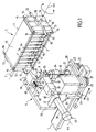
- the device represented in FIGS. 1 to 3 comprises a cassette support 1 rotatably mounted around a longitudinal shaft 2 of axis XX and suitable for holding two cassettes 3 (only one of which is visible in FIG. 1) in which are arranged and aligned side by side several tubes 4, each of which contains a blood product and is closed by a stopper 5.
- the device further comprises a sampling station 6 displaceable in translation on a slide 7 extending parallel to the axis XX and comprising a sampling needle 8 movable vertically and the tip of which is directed upwards.
- the sampling station 6 further comprises a gripper 9 movable in translation in a direction of axis YY, orthogonal to axis XX, this clamp 9 being suitable for gripping a tube chosen 4 in one of the cassettes 3 to bring it to the sampling station 6, in the axis of the needle 8, so that the latter takes a sample of blood product by piercing the stopper then aspiration, and then bringing the tube back 4 at the location it occupied in cassette 3.
- the support 1 essentially comprises two rectangular plates 10 extending parallel to each other and on either side of the shaft 2, said plates being connected by two end spacers 11 integral with the rotation shaft 2.
- the plates 10 and the spacers 11 together define two opposite U-shaped cradles forming housings to keep the two cassettes 3 in head to tail position.
- the tubes 4 of the cassette 3 close to the sampling station are in the same substantially vertical plane, the caps being directed downwards, while the tubes of the other cassette 3 are in a another substantially vertical plane, parallel to the aforementioned plane, the plugs of the tubes being directed upwards.
- the tubes are in a non-radial position relative to the axis XX.
- the support 1 further comprises, at each end spacer 11, two guides 12 extending in directions substantially parallel to the plates 10 and serving to guide the cassettes 3 when they are loaded onto the support 1 or when they are extraction, as described in publication WO 93/25 885 already cited.
- Each of the cassettes 3 forms a flat container which comprises two end flanges 13 connected to each other by two bars 14 and 15 and a bottom 16 on which are mounted elastic clips 17 in the shape of a U suitable for holding tubes 4 of lengths and / or of different diameters.
- each cassette can contain ten tubes.
- Each of the flanges 13 includes a cutout 18 for the passage of the guides 12.
- the support 1 comprises four pairs of elastic clips 19 suitable for cooperating with the flanges 13 of the cassettes 3 to keep them immobilized relative to the support.
- the cassettes 3 can be loaded automatically onto the support 1 from a charger (not shown) arranged above the support, the latter being in a position such that the guides 12 extend vertically.
- the cassettes 3 can also be extracted from the support in a substantially horizontal direction when the support occupies the position of FIG. 1, the cassette being extracted to the right, that is to say opposite to the sampling station.
- the support 1 can be rotated about its axis XX by a suitable motor (not shown) to impart to it a complete rotational movement or alternating rotational movements, and this in a controlled manner, to agitate the tubes.
- the sampling station 6 comprises a base 20 movable in translation along the slide 7 by means of rollers 21, in one direction or the other, as shown by the double arrow F1.
- the displacement of the base 20 can be carried out by any suitable actuator, for example by an electric motor M (not shown) rotating a threaded rod (not shown) associated with a nut (not shown) integral with the base 20.
- the actuator is designed to move the base incrementally to bring, in a controlled manner, the gripper 9 to the right of a chosen tube 4 contained in the cassette 3.
- the sampling needle 8 is mounted on a plate 22 capable of sliding vertically on guide columns 23, which extend perpendicular to the base 20, under the action of a double-acting pneumatic cylinder 24.
- This jack 24 comprises a body 25 mounted on the plate 22 and a rod (not shown) bearing on the base 20.
- the cylinder rod When the cylinder rod is deployed, the plate 22 moves away from the base 20 and the needle 8 moves vertically upwards. Conversely, when the actuator rod is retracted, the plate 22 approaches the base 20 and the needle 8 moves vertically downwards.
- the displacement is represented by the double arrow F2 in FIG. 3.
- the sampling station 6 further comprises a vertical plate 26 attached perpendicularly to the base 20 and forming a support for various members of the sampling station.
- a flange 27 supporting, by its body 28, a double-acting pneumatic cylinder 29, the rod 30 of which carries, at its free end, the gripper 9.
- the cylinder 29 thus makes it possible to move the gripper gripping in the direction of the YY axis in one direction or the other to move the clamp, either in the direction of the cassette 3, or in the direction of the sampling station (double arrow F3 in FIG. 2).
- the clamp 9 comprises two jaws 31 capable of being moved towards or away from one another by pivoting about an axis parallel to the direction of the tubes 4. These jaws 31 are mounted on a support 32 carried by the rod 30 of the cylinder and can be moved towards or away from each other by an actuator 33 which, in the example, is a double-acting pneumatic cylinder.
- the plate 26 of the station 6 further carries a rinsing member 34 used for cleaning the sampling needle 8 after each sampling operation.
- the plate 26 supports a first fixed stop 35 capable of forming a support for the stopper 5 of the tube, when the latter is held in the sampling position in the axis of the needle 8 by the gripping pliers 9.
- the plate 26 further supports a second stop 36 which is adjustable and capable of forming a support for the bottom of the tube when the latter is held in the sampling position.
- This second stop 36 is adjustable to adapt automatically to the length of the tube, the latter being able to assume values determined in advance.
- the second stop 36 includes a step block 37 whose structure will be defined later.
- This block 37 is slidably mounted on two guide rods 38 which extend parallel to the axis YY and therefore orthogonally to the axis XX, these two rods being supported by a flange 39 attached to the plate 26.
- An elastic spring of recall 40 is interposed between the block 37 and the flange 39 so as to urge the block 37 in the direction of the cassette support.
- the block 37 can thus be moved in translation orthogonally to the axis XX and in both directions, as shown by the double arrow F4 in FIG. 2.
- the rod 30 of the jack 29 is developed to position the jaws 31, still open, of the gripper 9 around the chosen tube, the support 1 being immobilized.
- the tube chosen is the third tube from the left in the series, as shown in FIG. 2.
- the two jaws 31 of the clamp are then brought together by the jack 33, as shown by the arrows F5 in FIG. 2.
- the approach movement of the clamp 9 is effected by a displacement in a general direction transverse to the axis of the tube, the gripping of the tube being effected from the side .
- the tube retains substantially the same spatial orientation with its cap facing downwards.
- the jaws 31 of the clamp are advantageously made of a flexible material to grip, without breaking it, the wall of the tube which is usually made of glass.
- the rod 30 of the jack 29 is retracted (arrow F3), which makes it possible to bring the tube 3 into the sampling position shown in FIG. 3.
- the plug 5 of the tube 4 is in abutment against the fixed stop 35 and its bottom pressing against the adjustable stop 36.
- the rod of the jack 24 is retracted (arrow F2), the sampling needle 8 being in the low position.
- the rod of the actuator 24 is developed to cause the displacement of the sampling needle 8 upward, so that its tip pierces the stopper 5 to allow the sampling of a blood product sample by suction means. appropriate (not shown).
- the sampling needle 8 is lowered and the rod of the jack 29 is developed to move the tube 4 and deposit it in the cassette at the location it initially occupied.
- the gripping pliers then occupies a depositing position which corresponds to the gripping position in FIG. 2.
- the clip 17 automatically moves away and then maintains the tube in position.
- the clamp is then returned to the starting position of Figure 1, so that the device can be subjected to other similar operating cycles.
- the sampling station 6 is moved in translation along the slide 7 so that the gripper 9 is located opposite the chosen tube.
- the movements of the gripper are always carried out in a direction transverse to the axis of the tube, the latter being grasped or replaced by lateral grip. It should be noted that during the actual sampling ( Figure 3), the support 1 is normally rotated, which allows the other tubes to be agitated.
- FIG. 4 shows an alternative embodiment of the gripper 9.
- the body 28 of the cylinder 29 is offset laterally relative to the jaws 31.
- the rod 30 of the cylinder 28 is coupled to a bracket 41 which carries the support 32 on which are mounted, on one side the actuator 33, and on the other side the two jaws 31 of the clamp.
- the two jaws 31 are carried by two crossed levers 42 pivotally mounted around a common pivot 43 and having respective buttonholes 44 crossed by a stud 45 mounted transversely at the end of the actuator rod 33.
- the two jaws of the clamp hold the fourth tube of a series of ten tubes in the picking position.
- the two jaws 31 are separated and are ready to grip the tenth tube of this series of ten tubes.
- the cassette support is rotated 180 ° to bring the other cassette opposite the sampling station, the caps of the tubes of this other cassette automatically pointing down.
- the sampling station and the gripper can be actuated again to perform similar operations on the tubes of the second cassette.
- the fixed stop 35 has a bearing surface 46 which extends perpendicular to the axis ZZ of movement of the needle 8 and which can be crossed by the latter.
- This surface 46 is continues laterally, on the side of the cassette support, by a ramp 47 which facilitates the guiding of the stopper 5 of the tube, as the latter approaches the sampling position, in which the axis of the tube is aligned with the axis ZZ of the needle 8.
- the tubes of the plugs 5 always come to rest on the bar 15, whatever the diameter and the length of the tubes, to provide a positioning mark.
- the step block 37 of the adjustable stop 36 is designed to automatically adapt to tubes of different lengths of given value, in the example three tube lengths: a length L1 (long tubes), a length L2 (medium tubes ) and a length L3 (short tubes).
- the step block 37 has for this purpose three bearing surfaces 48-1, 48-2 and 48-3 which have both a longitudinal offset (parallel to the direction of translation ZZ of the sampling needle) and a lateral offset (perpendicular to the direction of translation ZZ of the needle).
- the three bearing surfaces 48-1, 48-2 and 48-3 form a kind of staircase and are interconnected by transverse walls 49 and 50.
- the distance which separates the plane from the bearing surface 46 to respective planes of the bearing surfaces 48-1, 48-2 and 48-3, corresponds respectively to the lengths L1, L2 and L3 (caps included).
- the bearing surface 48-3 corresponding to the short tubes is located in the axis of movement ZZ of the sampling needle (FIG. 5).
- the gripper 9 grasps a tube 5 of length L1 (FIG. 5) to move it to the sampling position (FIG. 6).
- the bottom 51 of the tube 20 comes to bear laterally against the transverse surface 49 of the block 37 and thus move this block, against the force of the spring 40, until the bearing surface 48-1 is located in the axis of the sampling needle.
- a medium tube of length L2 is used, the bottom of the tube comes, during displacement, press against the transverse surface 50 and bring the bearing surface 48-2 in the extension of the axis of movement ZZ of the needle (FIG. 7).
- the device of the invention allows better agitation of blood products because the cassette holder can be driven in movement, before, during and after the sampling operations. It only needs to be temporarily immobilized when the gripping means come to grip a tube in a cassette for its removal, and when they then come to replace it in the cassette, once the removal has taken place.
- the gripping means may comprise one or more gripping pliers for gripping one or more tubes at the same time in a cassette.
- the cassette support is not necessarily a support rotatably mounted about an axis. It can be another type of support ensuring the stirring of the samples by tilting, inversion, or even rotation of the tubes on themselves.
- the tubes are oriented with their caps down for sampling, this arrangement is not compulsory, and it can be envisaged that the tubes are directed with their caps upwards, the sampling needle then being located above the stopper in the sampling position.
- actuation means ensuring the movement of the gripping means with respect to the support and to the sampling station are also not limited to the embodiment described above.
- the cassette support and the sampling station can both be located in fixed locations of a hematological analyzer, the drive means then ensuring the movement of the gripping means in crossed or orthogonal movements.
- the sampling station is in a fixed location of a hematology analyzer, while the cassette support is movable in this hematology analyzer, the drive means then comprising first means for moving the following cassette support a direction generally parallel to the direction of alignment of the tubes in the cassettes and of second means for moving the gripping means in a direction transverse to the direction of movement of the cassette support.
- the gripping means can approach or move away from or from each tube chosen by a movement taking place in the axis of the tube and not transversely to this axis, as in the embodiment described by way of example.
- the gripping means pass through the cassette to take one or more tubes on the way and bring them to the sampling station.
- the actuation means can be controlled by a programmable controller or any other suitable means.
- the device of the invention can advantageously be combined with automatic transfer means for loading the cassettes into the support before removal and then extracting them from the support after removal, as taught for example in the publication WO 93/25 885 already cited.
- the device of the invention thus finds application to hematological analyzers, such as those used in laboratories, the samples taken being then brought into contact with suitable reagents for analysis purposes.
Landscapes
- General Health & Medical Sciences (AREA)
- Health & Medical Sciences (AREA)
- Life Sciences & Earth Sciences (AREA)
- Chemical & Material Sciences (AREA)
- Analytical Chemistry (AREA)
- Biochemistry (AREA)
- Physics & Mathematics (AREA)
- General Physics & Mathematics (AREA)
- Immunology (AREA)
- Pathology (AREA)
- Automatic Analysis And Handling Materials Therefor (AREA)
- Sampling And Sample Adjustment (AREA)
- Investigating Or Analysing Biological Materials (AREA)
Applications Claiming Priority (2)
| Application Number | Priority Date | Filing Date | Title |
|---|---|---|---|
| FR9501397 | 1995-02-07 | ||
| FR9501397A FR2730315B1 (fr) | 1995-02-07 | 1995-02-07 | Dispositif d'agitation et de prelevement d'echantillons de produits sanguins dans des tubes regroupes dans des cassettes |
Publications (2)
| Publication Number | Publication Date |
|---|---|
| EP0726453A1 true EP0726453A1 (de) | 1996-08-14 |
| EP0726453B1 EP0726453B1 (de) | 2002-05-29 |
Family
ID=9475913
Family Applications (1)
| Application Number | Title | Priority Date | Filing Date |
|---|---|---|---|
| EP96400234A Expired - Lifetime EP0726453B1 (de) | 1995-02-07 | 1996-02-02 | Vorrichtung zum Rühren und Entnehmen von Blutprodukten aus Proberöhrchen die in einen Gestell angeordnet sind |
Country Status (8)
| Country | Link |
|---|---|
| US (1) | US5665309A (de) |
| EP (1) | EP0726453B1 (de) |
| JP (1) | JPH08248036A (de) |
| BR (1) | BR9600549A (de) |
| DE (1) | DE69621361T2 (de) |
| ES (1) | ES2175045T3 (de) |
| FR (1) | FR2730315B1 (de) |
| HU (1) | HU220008B (de) |
Cited By (7)
| Publication number | Priority date | Publication date | Assignee | Title |
|---|---|---|---|---|
| US5788722A (en) * | 1986-10-16 | 1998-08-04 | Exxon Chemical Patents Inc | High functionality low molecular weight oil soluble dispersant additives useful in oleaginous compositions |
| FR2858057A1 (fr) * | 2003-07-21 | 2005-01-28 | Abx Sa | Dispositif de controle de qualite pour analyseur sanguin fonctionnant en sang total |
| WO2010014656A2 (en) * | 2008-07-31 | 2010-02-04 | Hamilton Storage Technologies, Inc. | Tube picking mechanism for an automated, ultra-low temperature storage and retrieval system |
| WO2017081413A1 (fr) * | 2015-11-13 | 2017-05-18 | Horiba Abx Sas | Dispositif d'agitation et de prélèvement d'échantillons de liquides biologiques adapté pour trier |
| WO2017081411A1 (fr) * | 2015-11-13 | 2017-05-18 | Horiba Abx Sas | Dispositif d'agitation et de prélèvement d'échantillons de liquides biologiques adapté pour trier |
| WO2017081410A1 (fr) * | 2015-11-13 | 2017-05-18 | Horiba Abx Sas | Dispositif d'agitation et de prelevement d'echantillons de liquides |
| CN110064458A (zh) * | 2019-03-15 | 2019-07-30 | 温州市中心医院 | 一种方便取用的血液储存装置 |
Families Citing this family (42)
| Publication number | Priority date | Publication date | Assignee | Title |
|---|---|---|---|---|
| US5916527A (en) * | 1997-03-04 | 1999-06-29 | Beckwell International, Inc. | Convertible stand and container and method |
| US5861563A (en) * | 1997-03-20 | 1999-01-19 | Bayer Corporation | Automatic closed tube sampler |
| US6050719A (en) * | 1998-01-30 | 2000-04-18 | Affymetrix, Inc. | Rotational mixing method using a cartridge having a narrow interior |
| US6562299B1 (en) | 1998-09-18 | 2003-05-13 | Cytyc Corporation | Method and apparatus for preparing cytological specimens |
| US6177050B1 (en) * | 1998-11-18 | 2001-01-23 | Lab-Interlink, Inc. | Container positioning device |
| US6203760B1 (en) * | 1999-02-12 | 2001-03-20 | Perkinelmer Instruments Llc | Autosampler having gripper with shape memory metal actuator |
| JP2003500673A (ja) * | 1999-05-27 | 2003-01-07 | ピーイー コーポレイション (エヌワイ) | 反応プレートの正確な位置決めのための装置および方法 |
| WO2001067067A2 (en) † | 2000-03-08 | 2001-09-13 | Cytyc Corporation | Method and apparatus for preparing cytological specimens |
| SE517143C2 (sv) * | 2000-04-03 | 2002-04-23 | Delaval Holding Ab | Anordning och förfarande för provtagning av mjölk |
| FR2812088B1 (fr) * | 2000-07-21 | 2003-01-24 | Abx Sa | Dispositif de traitement d'echantillons de produits sanguins |
| KR100646225B1 (ko) * | 2000-07-21 | 2006-11-17 | 아 베 익스 | 혈액 산물 시료 처리용 장치 |
| US6588625B2 (en) * | 2001-04-24 | 2003-07-08 | Abbott Laboratories | Sample handling system |
| US7458483B2 (en) | 2001-04-24 | 2008-12-02 | Abbott Laboratories, Inc. | Assay testing diagnostic analyzer |
| US6999847B2 (en) | 2002-07-26 | 2006-02-14 | Unelab Llc | Specimen carrier transfer apparatus for a conveyor track |
| FR2859285B1 (fr) * | 2003-08-26 | 2007-08-10 | Abx Sa | Analyseur hematologique sur sang total avec dispositif d'agitation |
| JP4652717B2 (ja) * | 2004-04-26 | 2011-03-16 | 株式会社ミツトヨ | 画像処理装置及び方法並びにプログラム |
| EP1655071A1 (de) * | 2004-11-04 | 2006-05-10 | F. Hoffmann-La Roche Ag | Röhrchenständer mit einem beweglichen Teil zum Schütteln der Probe |
| EP1655609B1 (de) * | 2004-11-04 | 2013-09-18 | F.Hoffmann-La Roche Ag | Röhrchenständer mit einem beweglichen Teil zum Schütteln der Probe |
| US7481978B2 (en) * | 2005-03-23 | 2009-01-27 | Beckman Coulter, Inc. | Apparatus for aspirating liquids from sealed containers |
| US7628954B2 (en) | 2005-05-04 | 2009-12-08 | Abbott Laboratories, Inc. | Reagent and sample handling device for automatic testing system |
| US7815621B2 (en) | 2005-07-07 | 2010-10-19 | Eisai R & D Management Co. Ltd. | Recovery system |
| JP4890070B2 (ja) * | 2006-03-31 | 2012-03-07 | シスメックス株式会社 | 分析装置 |
| GB0601707D0 (en) * | 2006-01-27 | 2006-03-08 | Randox Lab Ltd | Assay Device Processing Apparatus And Method |
| FR2907905B1 (fr) * | 2006-10-30 | 2009-04-03 | C2 Diagnostics Sa | "appareil et procede pour manipuler des tubes,notamment appareil automate d'analyse sanguine" |
| US20080156377A1 (en) * | 2006-12-29 | 2008-07-03 | Brad Mann | Recovery system |
| JP5166996B2 (ja) * | 2008-06-30 | 2013-03-21 | シスメックス株式会社 | 分析装置 |
| US9602777B2 (en) | 2008-04-25 | 2017-03-21 | Roche Diagnostics Hematology, Inc. | Systems and methods for analyzing body fluids |
| WO2012030313A1 (en) * | 2008-04-25 | 2012-03-08 | James Winkelman | Method of determining a complete blood count and a white blood cell differential count |
| WO2010132823A2 (en) * | 2009-05-15 | 2010-11-18 | Biomerieux, Inc. | System and methods for rapid identification and/or characterization of a microbial agent in a sample |
| CN104774754B (zh) * | 2009-05-15 | 2017-11-17 | 生物梅里埃有限公司 | 用于微生物检测设备的自动化加载机构 |
| US9381524B2 (en) | 2011-11-08 | 2016-07-05 | Becton, Dickinson And Company | System and method for automated sample preparation |
| CN103364577B (zh) * | 2012-03-29 | 2014-11-26 | 深圳市开立科技有限公司 | 用于血细胞分析仪的进样取样装置 |
| JP6026182B2 (ja) * | 2012-08-30 | 2016-11-16 | シスメックス株式会社 | 検体処理装置および検体処理装置における検体の攪拌方法 |
| EP2901164A1 (de) | 2012-09-27 | 2015-08-05 | PZ Cormay S.A. | Verfahren und vorrichtung zur abgabe einer flüssigkeitsprobe an eine analysevorrichtung |
| JPWO2014054183A1 (ja) * | 2012-10-05 | 2016-08-25 | 株式会社安川電機 | 自動調製システム |
| WO2015111526A1 (ja) * | 2014-01-27 | 2015-07-30 | 株式会社 日立ハイテクノロジーズ | 自動分析装置 |
| JP6509218B2 (ja) * | 2014-07-18 | 2019-05-08 | 株式会社日立ハイテクノロジーズ | 自動分析装置 |
| US10334830B2 (en) * | 2015-11-20 | 2019-07-02 | Anthony Constantin Demetrescu | Robotics system for culturing and conducting experiments on caenorhabditis elegans |
| CN113751095B (zh) | 2015-12-11 | 2024-01-09 | 巴布森诊断公司 | 用于从全血分离血清或血浆的样品容器和方法 |
| WO2020037670A1 (zh) * | 2018-08-24 | 2020-02-27 | 深圳迈瑞生物医疗电子股份有限公司 | 血样分析仪及血样混匀方法 |
| US12050052B1 (en) | 2021-08-06 | 2024-07-30 | Babson Diagnostics, Inc. | Refrigerated carrier device for biological samples |
| US12025629B2 (en) | 2022-04-06 | 2024-07-02 | Babson Diagnostics, Inc. | Automated centrifuge loader |
Citations (6)
| Publication number | Priority date | Publication date | Assignee | Title |
|---|---|---|---|---|
| US4921676A (en) * | 1987-01-29 | 1990-05-01 | Toa Medical Electronics Co., Ltd. | Shaking apparatus for agitating and withdrawing a specimen in a sealed vessel |
| WO1992005448A2 (en) * | 1990-09-18 | 1992-04-02 | Anagen Limited | Assay or reaction apparatus |
| EP0557828A1 (de) * | 1992-02-22 | 1993-09-01 | Horiba, Ltd. | Aufbereitungsvorrichtung, zu verwenden in der Analyse |
| WO1993025885A1 (fr) * | 1992-06-11 | 1993-12-23 | Abx | Dispositif de transfert, d'agitation et de prelevement d'echantillons de produits sanguins en tubes regroupes dans des cassettes |
| EP0581984A1 (de) * | 1992-08-04 | 1994-02-09 | Hewlett-Packard GmbH | Vorrichtung zur Behandlung von Fiolen in einem "Analyseapparat" |
| DE4117780A1 (de) * | 1991-05-31 | 1994-02-10 | Die Erben Des Verstorbenen Sch | Milchsammelwagen-Probeflaschen-Mehrbehälter-Verfahren, getrennt für Transport und Analyse von MSW-Milchproben |
Family Cites Families (8)
| Publication number | Priority date | Publication date | Assignee | Title |
|---|---|---|---|---|
| SE428609B (sv) * | 1981-03-20 | 1983-07-11 | Coulter Electronics | Provvexlare for blandning och provtagning av blod eller liknande sedimenterande vetskor |
| US4387076A (en) * | 1981-10-14 | 1983-06-07 | Coulter Electronics, Inc. | Sample feeding arrangement |
| US4609017A (en) * | 1983-10-13 | 1986-09-02 | Coulter Electronics, Inc. | Method and apparatus for transporting carriers of sealed sample tubes and mixing the samples |
| FR2598350B1 (fr) * | 1986-05-06 | 1989-11-17 | Bp Chimie Sa | Procede et dispositif pour degazer et pour transformer en granules des particules de polyolefines obtenues par polymerisation en phase gazeuse |
| FR2604789B1 (fr) * | 1986-10-06 | 1989-07-28 | Abx Sa | Dispositif de prelevement automatique de liquide dans un flacon |
| EP0315757A3 (de) * | 1987-11-12 | 1991-03-06 | Oerlikon-Contraves AG | Verfahren und Vorrichtung zum Speichern und Mischen von Blutproben |
| US4927545A (en) * | 1988-10-06 | 1990-05-22 | Medical Automation Specialties, Inc. | Method and apparatus for automatic processing and analyzing of blood serum |
| US5525298A (en) * | 1991-04-19 | 1996-06-11 | Olympus Optical Co., Ltd. | Apparatus for taking liquid content for use in analysis out of container |
-
1995
- 1995-02-07 FR FR9501397A patent/FR2730315B1/fr not_active Expired - Fee Related
-
1996
- 1996-01-30 HU HU9600204A patent/HU220008B/hu not_active IP Right Cessation
- 1996-02-02 ES ES96400234T patent/ES2175045T3/es not_active Expired - Lifetime
- 1996-02-02 EP EP96400234A patent/EP0726453B1/de not_active Expired - Lifetime
- 1996-02-02 DE DE69621361T patent/DE69621361T2/de not_active Expired - Fee Related
- 1996-02-07 JP JP8021547A patent/JPH08248036A/ja active Pending
- 1996-02-07 BR BR9600549A patent/BR9600549A/pt active Search and Examination
- 1996-02-07 US US08/597,969 patent/US5665309A/en not_active Expired - Fee Related
Patent Citations (6)
| Publication number | Priority date | Publication date | Assignee | Title |
|---|---|---|---|---|
| US4921676A (en) * | 1987-01-29 | 1990-05-01 | Toa Medical Electronics Co., Ltd. | Shaking apparatus for agitating and withdrawing a specimen in a sealed vessel |
| WO1992005448A2 (en) * | 1990-09-18 | 1992-04-02 | Anagen Limited | Assay or reaction apparatus |
| DE4117780A1 (de) * | 1991-05-31 | 1994-02-10 | Die Erben Des Verstorbenen Sch | Milchsammelwagen-Probeflaschen-Mehrbehälter-Verfahren, getrennt für Transport und Analyse von MSW-Milchproben |
| EP0557828A1 (de) * | 1992-02-22 | 1993-09-01 | Horiba, Ltd. | Aufbereitungsvorrichtung, zu verwenden in der Analyse |
| WO1993025885A1 (fr) * | 1992-06-11 | 1993-12-23 | Abx | Dispositif de transfert, d'agitation et de prelevement d'echantillons de produits sanguins en tubes regroupes dans des cassettes |
| EP0581984A1 (de) * | 1992-08-04 | 1994-02-09 | Hewlett-Packard GmbH | Vorrichtung zur Behandlung von Fiolen in einem "Analyseapparat" |
Cited By (18)
| Publication number | Priority date | Publication date | Assignee | Title |
|---|---|---|---|---|
| US5788722A (en) * | 1986-10-16 | 1998-08-04 | Exxon Chemical Patents Inc | High functionality low molecular weight oil soluble dispersant additives useful in oleaginous compositions |
| FR2858057A1 (fr) * | 2003-07-21 | 2005-01-28 | Abx Sa | Dispositif de controle de qualite pour analyseur sanguin fonctionnant en sang total |
| WO2005019835A1 (fr) * | 2003-07-21 | 2005-03-03 | Horiba Abx Sa. | Dispositif de controle de qualite pour un analyseur sanguin fonctionnant en sang total |
| AU2004267523B2 (en) * | 2003-07-21 | 2010-01-28 | Horiba Abx S.A. | Quality control device for a blood analyser using whole blood |
| US8029732B2 (en) | 2003-07-21 | 2011-10-04 | Horiba Abx Sa | Quality control device for a blood analyser using whole blood |
| WO2010014656A2 (en) * | 2008-07-31 | 2010-02-04 | Hamilton Storage Technologies, Inc. | Tube picking mechanism for an automated, ultra-low temperature storage and retrieval system |
| WO2010014656A3 (en) * | 2008-07-31 | 2013-05-02 | Hamilton Storage Technologies, Inc. | Tube picking mechanism for an automated, ultra-low temperature storage and retrieval system |
| WO2017081411A1 (fr) * | 2015-11-13 | 2017-05-18 | Horiba Abx Sas | Dispositif d'agitation et de prélèvement d'échantillons de liquides biologiques adapté pour trier |
| WO2017081413A1 (fr) * | 2015-11-13 | 2017-05-18 | Horiba Abx Sas | Dispositif d'agitation et de prélèvement d'échantillons de liquides biologiques adapté pour trier |
| WO2017081410A1 (fr) * | 2015-11-13 | 2017-05-18 | Horiba Abx Sas | Dispositif d'agitation et de prelevement d'echantillons de liquides |
| FR3043783A1 (fr) * | 2015-11-13 | 2017-05-19 | Horiba Abx Sas | Dispositif d'agitation et de prelevement d'echantillons de liquides biologiques adapte pour trier |
| FR3043781A1 (fr) * | 2015-11-13 | 2017-05-19 | Horiba Abx Sas | Dispositif d'agitation et de prelevement d'echantillons de liquides biologiques |
| FR3043782A1 (fr) * | 2015-11-13 | 2017-05-19 | Horiba Abx Sas | Dispositif d'agitation et de prelevement d'echantillons de liquides biologiques adapte pour trier |
| CN108603891A (zh) * | 2015-11-13 | 2018-09-28 | 奥里巴Abx股份有限公司 | 适于分选的用于生物流体样本混匀和采样的装置 |
| US10794922B2 (en) | 2015-11-13 | 2020-10-06 | Horiba Abx Sas | Device for agitating and collecting liquid samples |
| CN108603891B (zh) * | 2015-11-13 | 2022-03-11 | 奥里巴Abx股份有限公司 | 适于分选的用于生物流体样本混匀和采样的装置 |
| US12005409B2 (en) | 2015-11-13 | 2024-06-11 | Horiba Abx Sas | Device for agitating and collecting biological liquid samples suitable for sorting |
| CN110064458A (zh) * | 2019-03-15 | 2019-07-30 | 温州市中心医院 | 一种方便取用的血液储存装置 |
Also Published As
| Publication number | Publication date |
|---|---|
| BR9600549A (pt) | 1997-12-30 |
| DE69621361D1 (de) | 2002-07-04 |
| HU9600204D0 (en) | 1996-03-28 |
| JPH08248036A (ja) | 1996-09-27 |
| US5665309A (en) | 1997-09-09 |
| DE69621361T2 (de) | 2003-01-02 |
| FR2730315B1 (fr) | 1997-03-21 |
| HUP9600204A3 (en) | 1999-01-28 |
| ES2175045T3 (es) | 2002-11-16 |
| EP0726453B1 (de) | 2002-05-29 |
| FR2730315A1 (fr) | 1996-08-09 |
| HU220008B (hu) | 2001-10-28 |
| HUP9600204A2 (en) | 1997-07-28 |
Similar Documents
| Publication | Publication Date | Title |
|---|---|---|
| EP0726453B1 (de) | Vorrichtung zum Rühren und Entnehmen von Blutprodukten aus Proberöhrchen die in einen Gestell angeordnet sind | |
| EP1174717B1 (de) | Vorrichtung zur Behandlung von Blutproben | |
| EP0984263B1 (de) | Vorrichtung zur automatischen Vorbereitung von Blutabstrichen auf Objekträgern | |
| CA2728587C (fr) | Pince adaptee pour saisir un support d'echantillons biologiques, ensemble d'un support echantillons biologiques et d'une pince adaptee, et automate de traitement et/ou d'analyse | |
| FR2810407A1 (fr) | Appareil pour l'analyse d'echantillons | |
| FR2477711A1 (fr) | Dispositif pour le prelevement d'echantillons a analyser, specialement dans des echantillonneurs automatiques | |
| FR2857750A1 (fr) | Dispositif et procede de prelevement pour un automate d'analyse | |
| EP3491394B1 (de) | Vorrichtung zum schütteln und entnehmen von biologischen flüssigkeiten | |
| FR2508016A1 (fr) | Dispositif pour prelever des pieces a travailler d'une pile | |
| FR2624412A1 (fr) | Manipulateur et dispositif de robotique en particulier pour cintreuse de toles | |
| EP0269529B1 (de) | Maschine zum automatischen Anbringen von selbstklebenden Folien auf Gegenständen | |
| EP0605316A1 (de) | Verfahren und Vorrichtung zur automatischen Sortierung von Kernbrennstofftabletten | |
| EP0393567A1 (de) | Verfahren und Vorrichtung zum Nieten eines Deckbandes an den Schaufelspitzen eines beschaufelten Rotors | |
| FR2609808A1 (fr) | Appareil pour la distribution de milieux dans des receptacles groupes sur des plaques | |
| FR2688205A1 (fr) | Systeme de manipulation d'objets notamment pour machine de tri automatique de courrier. | |
| FR2598336A1 (fr) | Manipulateur pour l'alimentation automatique des machines pour la centrifugation des bobines de fil | |
| EP0073687B1 (de) | Automatische Werkzeugwechselvorrichtung für eine Werkzeugmaschine | |
| FR2624407A1 (fr) | Installation de manipulation de livres ou autres objets plats disposes dans des bacs de stockage | |
| EP0617683B1 (de) | Vorrichtung zum trennen von zwei folien aus biegsamem material | |
| EP0329527A1 (de) | Zu- und Abführvorrichtung der Werkzeuge einer vertikalen Räummaschine | |
| EP0293275A1 (de) | Verfahren zum Umsetzen von Gegenständen von einem Förderer auf einen anderen und Vorrichtung zum Durchführen dieses Verfahrens | |
| EP0252844A1 (de) | Automatische Vorrichtung zum Bearbeiten, insbesondere zum Schneiden von Bändern | |
| FR2599994A1 (fr) | Procede et dispositif de selection et de manipulation d'objets parmi une collection de ceux-ci | |
| FR2601176A1 (fr) | Magasin a cassettes d'enregistrement de son et/ou d'images avec dispositif automatique de manipulation de cassettes entre ledit magasin et des appareils de lecture desdites cassettes. | |
| FR2608487A1 (fr) | Perfectionnements aux changeurs d'outil |
Legal Events
| Date | Code | Title | Description |
|---|---|---|---|
| PUAI | Public reference made under article 153(3) epc to a published international application that has entered the european phase |
Free format text: ORIGINAL CODE: 0009012 |
|
| AK | Designated contracting states |
Kind code of ref document: A1 Designated state(s): DE ES FR GB IT SE |
|
| 17P | Request for examination filed |
Effective date: 19970110 |
|
| 17Q | First examination report despatched |
Effective date: 20000918 |
|
| GRAG | Despatch of communication of intention to grant |
Free format text: ORIGINAL CODE: EPIDOS AGRA |
|
| GRAG | Despatch of communication of intention to grant |
Free format text: ORIGINAL CODE: EPIDOS AGRA |
|
| GRAH | Despatch of communication of intention to grant a patent |
Free format text: ORIGINAL CODE: EPIDOS IGRA |
|
| GRAH | Despatch of communication of intention to grant a patent |
Free format text: ORIGINAL CODE: EPIDOS IGRA |
|
| GRAA | (expected) grant |
Free format text: ORIGINAL CODE: 0009210 |
|
| AK | Designated contracting states |
Kind code of ref document: B1 Designated state(s): DE ES FR GB IT SE |
|
| REG | Reference to a national code |
Ref country code: GB Ref legal event code: FG4D Free format text: NOT ENGLISH |
|
| REF | Corresponds to: |
Ref document number: 69621361 Country of ref document: DE Date of ref document: 20020704 |
|
| GBT | Gb: translation of ep patent filed (gb section 77(6)(a)/1977) |
Effective date: 20020821 |
|
| REG | Reference to a national code |
Ref country code: ES Ref legal event code: FG2A Ref document number: 2175045 Country of ref document: ES Kind code of ref document: T3 |
|
| PLBE | No opposition filed within time limit |
Free format text: ORIGINAL CODE: 0009261 |
|
| STAA | Information on the status of an ep patent application or granted ep patent |
Free format text: STATUS: NO OPPOSITION FILED WITHIN TIME LIMIT |
|
| 26N | No opposition filed |
Effective date: 20030303 |
|
| PGFP | Annual fee paid to national office [announced via postgrant information from national office to epo] |
Ref country code: ES Payment date: 20050105 Year of fee payment: 10 |
|
| PGFP | Annual fee paid to national office [announced via postgrant information from national office to epo] |
Ref country code: FR Payment date: 20050120 Year of fee payment: 10 |
|
| PGFP | Annual fee paid to national office [announced via postgrant information from national office to epo] |
Ref country code: GB Payment date: 20050202 Year of fee payment: 10 |
|
| PGFP | Annual fee paid to national office [announced via postgrant information from national office to epo] |
Ref country code: SE Payment date: 20050215 Year of fee payment: 10 |
|
| PGFP | Annual fee paid to national office [announced via postgrant information from national office to epo] |
Ref country code: DE Payment date: 20050426 Year of fee payment: 10 |
|
| PG25 | Lapsed in a contracting state [announced via postgrant information from national office to epo] |
Ref country code: GB Free format text: LAPSE BECAUSE OF NON-PAYMENT OF DUE FEES Effective date: 20060202 |
|
| PG25 | Lapsed in a contracting state [announced via postgrant information from national office to epo] |
Ref country code: SE Free format text: LAPSE BECAUSE OF NON-PAYMENT OF DUE FEES Effective date: 20060203 Ref country code: ES Free format text: LAPSE BECAUSE OF NON-PAYMENT OF DUE FEES Effective date: 20060203 |
|
| PGFP | Annual fee paid to national office [announced via postgrant information from national office to epo] |
Ref country code: IT Payment date: 20060228 Year of fee payment: 11 |
|
| PG25 | Lapsed in a contracting state [announced via postgrant information from national office to epo] |
Ref country code: DE Free format text: LAPSE BECAUSE OF NON-PAYMENT OF DUE FEES Effective date: 20060901 |
|
| EUG | Se: european patent has lapsed | ||
| GBPC | Gb: european patent ceased through non-payment of renewal fee |
Effective date: 20060202 |
|
| REG | Reference to a national code |
Ref country code: FR Ref legal event code: ST Effective date: 20061031 |
|
| REG | Reference to a national code |
Ref country code: ES Ref legal event code: FD2A Effective date: 20060203 |
|
| PG25 | Lapsed in a contracting state [announced via postgrant information from national office to epo] |
Ref country code: FR Free format text: LAPSE BECAUSE OF NON-PAYMENT OF DUE FEES Effective date: 20060228 |
|
| PG25 | Lapsed in a contracting state [announced via postgrant information from national office to epo] |
Ref country code: IT Free format text: LAPSE BECAUSE OF NON-PAYMENT OF DUE FEES Effective date: 20070202 |