EP2293055B1 - Method and apparatus for controlling multi-gas sensor - Google Patents
Method and apparatus for controlling multi-gas sensor Download PDFInfo
- Publication number
- EP2293055B1 EP2293055B1 EP10173769.0A EP10173769A EP2293055B1 EP 2293055 B1 EP2293055 B1 EP 2293055B1 EP 10173769 A EP10173769 A EP 10173769A EP 2293055 B1 EP2293055 B1 EP 2293055B1
- Authority
- EP
- European Patent Office
- Prior art keywords
- concentration
- ammonia
- gas
- ammonia concentration
- sensor section
- Prior art date
- Legal status (The legal status is an assumption and is not a legal conclusion. Google has not performed a legal analysis and makes no representation as to the accuracy of the status listed.)
- Active
Links
- 238000000034 method Methods 0.000 title claims description 30
- QGZKDVFQNNGYKY-UHFFFAOYSA-N Ammonia Chemical compound N QGZKDVFQNNGYKY-UHFFFAOYSA-N 0.000 claims description 568
- 229910021529 ammonia Inorganic materials 0.000 claims description 273
- 239000007789 gas Substances 0.000 claims description 221
- 238000005259 measurement Methods 0.000 claims description 152
- 238000005086 pumping Methods 0.000 claims description 113
- 239000001301 oxygen Substances 0.000 claims description 83
- 229910052760 oxygen Inorganic materials 0.000 claims description 83
- QVGXLLKOCUKJST-UHFFFAOYSA-N atomic oxygen Chemical compound [O] QVGXLLKOCUKJST-UHFFFAOYSA-N 0.000 claims description 81
- 239000007784 solid electrolyte Substances 0.000 claims description 51
- 230000014509 gene expression Effects 0.000 description 85
- 238000001514 detection method Methods 0.000 description 46
- XSQUKJJJFZCRTK-UHFFFAOYSA-N Urea Chemical compound NC(N)=O XSQUKJJJFZCRTK-UHFFFAOYSA-N 0.000 description 18
- 239000004202 carbamide Substances 0.000 description 18
- 238000012545 processing Methods 0.000 description 17
- 238000009792 diffusion process Methods 0.000 description 16
- 238000006243 chemical reaction Methods 0.000 description 14
- 229910000069 nitrogen hydride Inorganic materials 0.000 description 14
- BASFCYQUMIYNBI-UHFFFAOYSA-N platinum Chemical compound [Pt] BASFCYQUMIYNBI-UHFFFAOYSA-N 0.000 description 14
- 238000002347 injection Methods 0.000 description 10
- 239000007924 injection Substances 0.000 description 10
- MCMNRKCIXSYSNV-UHFFFAOYSA-N Zirconium dioxide Chemical compound O=[Zr]=O MCMNRKCIXSYSNV-UHFFFAOYSA-N 0.000 description 8
- 238000004364 calculation method Methods 0.000 description 8
- 239000003054 catalyst Substances 0.000 description 7
- 239000000919 ceramic Substances 0.000 description 7
- 229910052697 platinum Inorganic materials 0.000 description 7
- 230000004913 activation Effects 0.000 description 6
- 230000008859 change Effects 0.000 description 6
- 239000011148 porous material Substances 0.000 description 6
- 239000000463 material Substances 0.000 description 5
- 239000000203 mixture Substances 0.000 description 5
- 230000001012 protector Effects 0.000 description 5
- IJGRMHOSHXDMSA-UHFFFAOYSA-N Atomic nitrogen Chemical compound N#N IJGRMHOSHXDMSA-UHFFFAOYSA-N 0.000 description 4
- PNEYBMLMFCGWSK-UHFFFAOYSA-N aluminium oxide Inorganic materials [O-2].[O-2].[O-2].[Al+3].[Al+3] PNEYBMLMFCGWSK-UHFFFAOYSA-N 0.000 description 4
- 238000009826 distribution Methods 0.000 description 4
- 229910052596 spinel Inorganic materials 0.000 description 4
- MWUXSHHQAYIFBG-UHFFFAOYSA-N Nitric oxide Chemical compound O=[N] MWUXSHHQAYIFBG-UHFFFAOYSA-N 0.000 description 3
- 230000003197 catalytic effect Effects 0.000 description 3
- 238000010531 catalytic reduction reaction Methods 0.000 description 3
- 238000010586 diagram Methods 0.000 description 3
- 238000011156 evaluation Methods 0.000 description 3
- 238000013213 extrapolation Methods 0.000 description 3
- 238000003780 insertion Methods 0.000 description 3
- 230000037431 insertion Effects 0.000 description 3
- 229910002915 BiVO4 Inorganic materials 0.000 description 2
- 229910026161 MgAl2O4 Inorganic materials 0.000 description 2
- VYPSYNLAJGMNEJ-UHFFFAOYSA-N Silicium dioxide Chemical compound O=[Si]=O VYPSYNLAJGMNEJ-UHFFFAOYSA-N 0.000 description 2
- 229910000416 bismuth oxide Inorganic materials 0.000 description 2
- 238000002485 combustion reaction Methods 0.000 description 2
- 238000002788 crimping Methods 0.000 description 2
- 238000000354 decomposition reaction Methods 0.000 description 2
- 230000006866 deterioration Effects 0.000 description 2
- TYIXMATWDRGMPF-UHFFFAOYSA-N dibismuth;oxygen(2-) Chemical compound [O-2].[O-2].[O-2].[Bi+3].[Bi+3] TYIXMATWDRGMPF-UHFFFAOYSA-N 0.000 description 2
- 230000000694 effects Effects 0.000 description 2
- PCHJSUWPFVWCPO-UHFFFAOYSA-N gold Chemical group [Au] PCHJSUWPFVWCPO-UHFFFAOYSA-N 0.000 description 2
- 239000010931 gold Substances 0.000 description 2
- 229910052737 gold Inorganic materials 0.000 description 2
- 238000004519 manufacturing process Methods 0.000 description 2
- 229910044991 metal oxide Inorganic materials 0.000 description 2
- 150000004706 metal oxides Chemical class 0.000 description 2
- 229910052757 nitrogen Inorganic materials 0.000 description 2
- 230000001590 oxidative effect Effects 0.000 description 2
- -1 oxygen ion Chemical class 0.000 description 2
- 238000012856 packing Methods 0.000 description 2
- 238000000926 separation method Methods 0.000 description 2
- 239000011029 spinel Substances 0.000 description 2
- 239000000454 talc Substances 0.000 description 2
- 229910052623 talc Inorganic materials 0.000 description 2
- 230000002411 adverse Effects 0.000 description 1
- HUUOUJVWIOKBMD-UHFFFAOYSA-N bismuth;oxygen(2-);vanadium Chemical compound [O-2].[O-2].[O-2].[O-2].[V].[Bi+3] HUUOUJVWIOKBMD-UHFFFAOYSA-N 0.000 description 1
- 238000004891 communication Methods 0.000 description 1
- 239000004020 conductor Substances 0.000 description 1
- KZHJGOXRZJKJNY-UHFFFAOYSA-N dioxosilane;oxo(oxoalumanyloxy)alumane Chemical compound O=[Si]=O.O=[Si]=O.O=[Al]O[Al]=O.O=[Al]O[Al]=O.O=[Al]O[Al]=O KZHJGOXRZJKJNY-UHFFFAOYSA-N 0.000 description 1
- GNTDGMZSJNCJKK-UHFFFAOYSA-N divanadium pentaoxide Chemical compound O=[V](=O)O[V](=O)=O GNTDGMZSJNCJKK-UHFFFAOYSA-N 0.000 description 1
- 239000000284 extract Substances 0.000 description 1
- WABPQHHGFIMREM-UHFFFAOYSA-N lead(0) Chemical compound [Pb] WABPQHHGFIMREM-UHFFFAOYSA-N 0.000 description 1
- 229910052751 metal Inorganic materials 0.000 description 1
- 239000002184 metal Substances 0.000 description 1
- 238000012986 modification Methods 0.000 description 1
- 230000004048 modification Effects 0.000 description 1
- 238000012544 monitoring process Methods 0.000 description 1
- 229910052863 mullite Inorganic materials 0.000 description 1
- 238000005457 optimization Methods 0.000 description 1
- 239000000843 powder Substances 0.000 description 1
- 230000009257 reactivity Effects 0.000 description 1
- 230000035945 sensitivity Effects 0.000 description 1
- 239000000377 silicon dioxide Substances 0.000 description 1
- 229910001220 stainless steel Inorganic materials 0.000 description 1
- 239000010935 stainless steel Substances 0.000 description 1
- 238000003466 welding Methods 0.000 description 1
Images


Classifications
-
- G—PHYSICS
- G01—MEASURING; TESTING
- G01N—INVESTIGATING OR ANALYSING MATERIALS BY DETERMINING THEIR CHEMICAL OR PHYSICAL PROPERTIES
- G01N27/00—Investigating or analysing materials by the use of electric, electrochemical, or magnetic means
- G01N27/26—Investigating or analysing materials by the use of electric, electrochemical, or magnetic means by investigating electrochemical variables; by using electrolysis or electrophoresis
- G01N27/416—Systems
- G01N27/417—Systems using cells, i.e. more than one cell and probes with solid electrolytes
- G01N27/419—Measuring voltages or currents with a combination of oxygen pumping cells and oxygen concentration cells
-
- G—PHYSICS
- G01—MEASURING; TESTING
- G01N—INVESTIGATING OR ANALYSING MATERIALS BY DETERMINING THEIR CHEMICAL OR PHYSICAL PROPERTIES
- G01N33/00—Investigating or analysing materials by specific methods not covered by groups G01N1/00 - G01N31/00
- G01N33/0004—Gaseous mixtures, e.g. polluted air
- G01N33/0009—General constructional details of gas analysers, e.g. portable test equipment
- G01N33/0027—General constructional details of gas analysers, e.g. portable test equipment concerning the detector
- G01N33/0036—Specially adapted to detect a particular component
- G01N33/0037—Specially adapted to detect a particular component for NOx
-
- G—PHYSICS
- G01—MEASURING; TESTING
- G01N—INVESTIGATING OR ANALYSING MATERIALS BY DETERMINING THEIR CHEMICAL OR PHYSICAL PROPERTIES
- G01N33/00—Investigating or analysing materials by specific methods not covered by groups G01N1/00 - G01N31/00
- G01N33/0004—Gaseous mixtures, e.g. polluted air
- G01N33/0009—General constructional details of gas analysers, e.g. portable test equipment
- G01N33/0027—General constructional details of gas analysers, e.g. portable test equipment concerning the detector
- G01N33/0036—Specially adapted to detect a particular component
- G01N33/0054—Specially adapted to detect a particular component for ammonia
-
- Y—GENERAL TAGGING OF NEW TECHNOLOGICAL DEVELOPMENTS; GENERAL TAGGING OF CROSS-SECTIONAL TECHNOLOGIES SPANNING OVER SEVERAL SECTIONS OF THE IPC; TECHNICAL SUBJECTS COVERED BY FORMER USPC CROSS-REFERENCE ART COLLECTIONS [XRACs] AND DIGESTS
- Y02—TECHNOLOGIES OR APPLICATIONS FOR MITIGATION OR ADAPTATION AGAINST CLIMATE CHANGE
- Y02A—TECHNOLOGIES FOR ADAPTATION TO CLIMATE CHANGE
- Y02A50/00—TECHNOLOGIES FOR ADAPTATION TO CLIMATE CHANGE in human health protection, e.g. against extreme weather
- Y02A50/20—Air quality improvement or preservation, e.g. vehicle emission control or emission reduction by using catalytic converters
Definitions
- the present invention relates to a method and apparatus for controlling a multi-gas sensor suitable for detection of the nitrogen oxide concentration and ammonia concentration of a gas under measurement.
- an NO X sensor which uses a solid electrolyte body so as to detect the NO X concentration of a gas under measurement
- an ammonia sensor which detects the ammonia concentration of a the gas under measurement by making use of a change in impedance between a pair of electrodes or a change in electromotive force generated therebetween.
- the proposed technique has a step in which the gas under measurement is brought into contact with NH 3 strong oxidizing catalyst so as to convert ammonia to NO X , and the overall NO X concentration is measured; and a step in which the gas under measurement is brought into contact with NH 3 weak oxidizing catalyst so as to convert a portion of ammonia to NO X , and the NO X concentration is measured.
- the NO X concentration and the ammonia concentration are calculated from two detection values obtained in these steps (see Patent Document 1).
- an ammonia sensor in which an NO X electrode, a reference electrode, a selection electrode, and an ammonia electrode are provided in the single sensor to thereby form a plurality of cells.
- a method of calculating ammonia concentration is changed in accordance with an electromotive force generated between the NO X electrode and the reference electrode as a result of introduction of a gas (in accordance with the state of presence of NO X ), whereby the ammonia concentration is measured accurately (see Patent Document 2).
- an electromotive force between the ammonia electrode and the reference electrode or an electromotive force between the NO X electrode and the ammonia electrode is selectively used for detection.
- Patent Document 1 since measurement is performed on the basis of a difference in catalytic performance, if the catalytic performance changes due to changes in measurement conditions (temperature, flow rate, pressure, etc.), accurate measurement cannot be performed. Moreover, in the case where the apparatus disposed in Patent Document 1 is disposed in a severe environment such as in exhaust gas of an automobile, it is difficult to stably maintain the catalytic performance over a long period of time.
- oxygen concentration may influence the measurement of ammonia concentration performed by use of an ammonia sensor; however, conventional ammonia sensors encounter difficulty in performing measurement in consideration of the influence of oxygen concentration.
- an object of the present invention is to provide a method and apparatus for controlling a multi-gas sensor which can measure NO X concentration and ammonia concentration by use of a single gas sensor and can improve accuracy in measurement of ammonia concentration.
- the present invention provides a method for controlling a multi-gas sensor comprising an NO X sensor section; and an ammonia sensor section formed on an outer surface of the NO X sensor section, wherein the NO X sensor section includes a first pumping cell which extends between the interior and exterior of a first measurement chamber, has paired first electrodes provided on a first solid electrolyte body, and is adapted to pump out or pump in oxygen of a gas under measurement introduced into the first measurement chamber, and a second pumping cell which extends between the interior and exterior of an NO X measurement chamber communicating with the first measurement chamber, has paired second electrodes provided on a second solid electrolyte body), and is configured such that a second pumping current flows between the paired second electrodes, the second pumping current corresponding to an NO X concentration of the gas under measurement having flowed into the NO X measurement chamber after adjustment of its oxygen concentration in the first measurement chamber; and the ammonia sensor section has at least a pair of electrodes formed on a solid electro
- the ammonia concentration can be accurately calculated without being affected by the oxygen concentration of the gas under measurement.
- the ammonia concentration can be calculated stably over a long period of time.
- the NO X sensor section and the ammonia sensor section are located at the same position, the sensor sections are placed under the same conditions (gas concentration, temperature distribution, etc.), whereby a measurement delay occurring in a certain sensor(s) can be suppressed.
- the method for controlling a multi-gas sensor of the present invention may be such that, in the case where the ammonia concentration output of the ammonia sensor section becomes 0 as a result of the ammonia concentration of the gas under measurement being set to 0, a first corrected NO concentration is calculated on the basis of the corrected ammonia concentration and the second pumping current.
- the second pumping current corresponding to the NO X concentration is affected by the ammonia concentration.
- the NO X concentration can be detected accurately without being affected by the concentration of the ammonia gas.
- this method is used when the gas under measurement does not contain NO 2 , and the NO concentration can be calculated accurately without being affected by the ammonia concentration of the gas under measurement.
- time when the ammonia concentration of the gas under measurement is set to 0 is a time when a predetermined period of time elapses after the stoppage of injection of aqueous urea into the gas under measurement.
- a phenomenon that the ammonia concentration becomes 0 at that timing is utilized, and the above-described method is used in the case where, when the ammonia concentration is measured by the ammonia sensor section exposed to the gas under measurement, the ammonia concentration output becomes 0 at that timing.
- the method for controlling a multi-gas sensor of the present invention may be such that, in the case where the ammonia concentration output of the ammonia sensor section becomes negative as a result of the ammonia concentration of the gas under measurement being set to 0, an expected NO 2 concentration is calculated in advance on the basis of the negative ammonia concentration output, and a second corrected NO concentration is calculated on the basis of the second pumping current and the expected NO 2 concentration.
- the second pumping current corresponding to the NO X concentration is affected by the ammonia concentration.
- the NO X concentration can be detected accurately without being affected by the concentration of the ammonia gas.
- this method is used when the gas under measurement contains NO 2 , and, even in the case where NO and NO 2 coexist in the gas under measurement, the NO concentration and the NO 2 concentration can be calculated separately and accurately.
- separation of NO and NO 2 is difficult.
- NO and NO 2 differ in molecular size. Therefore, even in the case where the above-mentioned second pumping current of the NO X sensor is the same, the calculated NO X concentration may change in accordance with the ratio between NO and NO 2 in the gas under measurement.
- time when the ammonia concentration of the gas under measurement is set to 0 is a time when a predetermined period of time elapses after the stoppage of injection of aqueous urea into the gas under measurement.
- a phenomenon that the ammonia concentration becomes 0 at that timing is utilized, and the above-described method is used in the case where, when the ammonia concentration is measured by the ammonia sensor section exposed to the gas under measurement, the ammonia concentration output becomes negative at that timing.
- the corrected ammonia concentration may be calculated on the basis of the expected NO 2 concentration as well as the oxygen concentration.
- the ammonia concentration is calculated in consideration of not only the oxygen concentration but also the NO 2 concentration. Therefore, the accuracy is further improved as compared with the case where the ammonia concentration is calculated in consideration of the oxygen concentration only.
- the present invention also provides an apparatus for controlling a multi-gas sensor comprising an NO X sensor section; and an ammonia sensor section formed on an outer surface of the NO X sensor section, wherein the NO X sensor section includes a first pumping cell which extends between the interior and exterior of a first measurement chamber, has paired first electrodes provided on a first solid electrolyte body, and is adapted to pump out or pump in oxygen of a gas under measurement introduced into the first measurement chamber, and a second pumping cell which extends between the interior and exterior of an NO X measurement chamber communicating with the first measurement chamber, has paired second electrodes provided on a second solid electrolyte body, and is configured such that a second pumping current flows between the paired second electrodes, the second pumping current corresponding to an NO X concentration of the gas under measurement having flowed into the NO X measurement chamber after adjustment of its oxygen concentration in the first measurement chamber; and the ammonia sensor section has at least a pair of electrodes formed on a solid electrolyte body and outputs an
- the ammonia concentration can be accurately calculated without being affected by the oxygen concentration of the gas under measurement.
- the ammonia concentration can be calculated stably over a long period of time.
- the NO X sensor section and the ammonia sensor section are located at the same position, the sensor sections are placed under the same conditions (gas concentration, temperature distribution, etc.), whereby a measurement delay occurring in a certain sensor(s) can be suppressed.
- the present invention it becomes possible to measure NO X concentration and ammonia concentration by use of a single gas sensor, and to improve accuracy in measurement of ammonia concentration.
- FIG. 1 shows a longitudinal cross section of a multi-gas sensor 200A, which is an example sensor to be controlled by a control method according to the embodiment of the present invention.
- the multi-gas sensor 200A is an assembly including a multi-gas sensor element section 100A for detecting ammonia concentration and NO X concentration.
- the multi-gas sensor 200A includes the plate-shaped multi-gas sensor element section 100A extending in an axial direction; a tubular metallic shell 138 having a screw portion 139 formed on an outer surface thereof for fixation to an exhaust pipe; a tubular ceramic sleeve 106 disposed to surround the circumference of the multi-gas sensor element section 100A; an insulating contact member 166 disposed such that the inner wall surface of a contact insertion hole 168 axially extending through the insulating contact member 166 surrounds the circumference of a rear end portion of the multi-gas sensor element section 100A; and a plurality of connection terminals 110 (in FIG. 1 , only two connection terminals are illustrated) disposed between the multi-gas sensor element section 100A and the insulating contact member 166.
- the metallic shell 138 which is formed into a generally tubular shape, has a through hole 154 axially extending through the metallic shell 138, and a ledge portion 152 projecting radially inward from the wall surface of the through hole 154.
- the metallic shell 138 holds the multi-gas sensor element section 100A in the through hole 154 such that a front end portion of the multi-gas sensor element section 100A is located frontward of the front end of the through hole 154, and electrode terminal portions 80A and 82A are located rearward of the rear end of the through hole 154.
- the ledge portion 152 has an inward taper surface which inclines in relation to a plane perpendicular to the axial direction.
- a ceramic holder 151, powder layers 153 and 156 (hereinafter may be referred to as "talc rings 153 and 156"), and the above-mentioned ceramic sleeve 106 are stacked in the through hole 154 of the metallic shell 138, in this sequence from the front end side toward the rear end side, so that they surround the circumference of the multi-gas sensor element section 100A.
- a crimping packing 157 is disposed between the ceramic sleeve 106 and a rear end portion 140 of the metallic shell 138.
- a metallic holder 158 for holding the talc ring 153 and the ceramic holder 151 and for maintaining airtightness is disposed between the ceramic holder 151 and the ledge portion 152 of the metallic shell 138.
- the rear end portion 140 of the metallic shell 138 is crimpled such that the rear end portion 140 presses the ceramic sleeve 106 frontward via the crimping packing 157.
- an outer protector 142 and an inner protector 143 which are formed of metal (e.g., stainless steel) and form a double protector, are attached to the outer circumference of a front end portion (a lower end portion in FIG. 1 ) of the metallic shell 138 by means of, for example, welding.
- the outer protector 142 and the inner protector 143 cover a projecting portion of the multi-gas sensor element section 100A, and each have a plurality of holes.
- An outer sleeve 144 is fixed to the outer circumference of a rear end portion of the metallic shell 138.
- a grommet 150 is disposed in an opening of the outer sleeve 144 located on the rear end side (on the upper side in FIG. 1 ) thereof.
- the grommet 150 has lead wire insertion holes 161, through which a plurality of lead wires 146 (only three of them are shown in FIG. 1 ) are inserted to be electrically connected to the electrode terminal portions 80A and 82A of the multi-gas sensor element section 100A. Notably, in FIG.
- electrode terminal portions on the front surface of the multi-gas sensor element section 100A and those on the back surface thereof are represented by the electrode terminal portions 80A and 82A, respectively.
- a plurality of electrode terminal portions are formed on each surface in accordance with the numbers of electrodes, etc. of an NO X sensor section 30A and an ammonia sensor section 42, which will be described later.
- the insulating contact member 166 is disposed at a rear end portion (an upper end portion in FIG. 1 ) of the multi-gas sensor element section 100A projecting from the rear end portion 140 of the metallic shell 138.
- the insulating contact member 166 is disposed to surround the electrode terminal portions 80A and 82A formed on the front and back surfaces of the multi-gas sensor element section 100A.
- the insulating contact member 166 which is formed into a tubular shape, has a contact insertion hole 168 axially extending through the insulating contact member 166, and a flange portion 167 projecting radially outward from an outer surface thereof.
- the insulating contact member 166 is disposed inside the outer sleeve 144 with its flange portion 167 being in contact with the outer sleeve 144 via a holding member 169.
- the connection terminals 110 disposed in the insulating contact member 166 are electrically connected to the electrode terminal portions 80A and 82A of the multi-gas sensor element section 100A, and electrically communicate with an external device via the lead wires 146.
- FIG. 2 is a block diagram showing the configuration of a multi-gas sensor control apparatus (controller) 300 according to the embodiment of the present invention, and the configuration of the multi-gas sensor element section 100A connected thereto. Notably, in order to facilitate description, FIG. 2 shows only a longitudinal cross section of the multi-gas sensor element section 100A accommodated within the multi-gas sensor 200A.
- the multi-gas sensor 200A (the multi-gas sensor element section 100A) and the multi-gas sensor control apparatus 300 are mounted on an unillustrated vehicle having an internal combustion engine (hereinafter may be referred to as the "engine"), and the multi-gas sensor control apparatus 300 is electrically connected to a vehicle-side control apparatus (hereinafter may be referred to as "ECU") 400.
- ECU vehicle-side control apparatus
- ends of the lead wires 146 extending from the multi-gas sensor 200A are connected to a connector, which is electrically connected to a connector of the multi-gas sensor control apparatus 300.
- the ECU 400 receives data representing the ammonia concentration and NO X concentration of exhaust gas calculated by the multi-gas sensor control apparatus 300, and executes various types of processing on the basis of the received data so as to control the operation status of the engine or remove NO X accumulated in a catalyst unit.
- the multi-gas sensor element section 100A includes the NO X sensor section 30A having a configuration similar to that of a known NO X sensor, and the ammonia sensor section 42 having a configuration similar to that of a known ammonia sensor. As will be described in detail later, the ammonia sensor section 42 is formed on the outer surface of the NO X sensor section 30A.
- the NO X sensor section 30A includes insulating layers 23f, a solid electrolyte body 25 for the ammonia sensor section, an insulating layer 23e, a first solid electrolyte body 2a, an insulating layer 23d, a third solid electrolyte body 6a, an insulating layer 23c, a second solid electrolyte body 4a, and insulating layers 23b and 23a, which are stacked in this sequence.
- a first measurement chamber S1 is formed between the first solid electrolyte body 2a and the third solid electrolyte body 6a.
- a gas under measurement is externally introduced into the first measurement chamber S1 via a first diffusion resistor 8a disposed at the left end (inlet) of the first measurement chamber S1.
- a protection layer 9 formed of a porous material is disposed on the outer side of the first diffusion resistor 8a.
- a second diffusion resistor 8b is disposed at the end of the first measurement chamber S1 opposite the inlet.
- a second measurement chamber (corresponding to the "NO X measurement chamber" of the present invention) S2 is defined on the right side of the first measurement chamber S1, and communicates with the first measurement chamber S1 via the second diffusion resistor 8b.
- the second measurement chamber S2 is formed between the first solid electrolyte body 2a and the second solid electrolyte body 4a such that the second measurement chamber S2 penetrates the third solid electrolyte body 6a.
- An elongated plate-shaped heater 21 is embedded between the insulating layers 23b and 23a such that the heater 21 extends along the longitudinal direction of the multi-gas sensor element section 100A.
- the heater 21 is used so as to heat the gas sensor to an activation temperature and enhance the oxygen ion conductivity of the solid electrolyte body, to thereby stabilize operation.
- Each of the insulating layers 23a, 23b, 23c, 23d, 23e, and 23f is mainly formed of alumina.
- Each of the first diffusion resistor 8a and the second diffusion resistor 8b is formed of a porous material such as alumina.
- the heater 21 is formed of platinum or the like.
- a first pumping cell 2 includes a first solid electrolyte body 2a mainly formed of zirconia having oxygen ion conductivity; and inner and outer (counter) first pumping electrodes 2b and 2c (corresponding to the "first electrodes" in claims) disposed to sandwich the first solid electrolyte body 2a.
- the inner first pumping electrode 2b faces the first measurement chamber S1.
- Each of the inner and outer first pumping electrodes 2b and 2c is mainly formed of platinum, and the surface of the inner first pumping electrode 2b is covered with a protection layer 11 formed of a porous material.
- a portion of the insulating layer 23e corresponding to the upper surface of the outer first pumping electrode 2c is removed so as to form an opening, and the opening is filled with a porous material 13.
- gas oxygen
- An oxygen concentration detection cell 6 includes a third solid electrolyte body 6a mainly formed of zirconia; and a detection electrode 6b and a reference electrode 6c disposed to sandwich the third solid electrolyte body 6a.
- the detection electrode 6b faces the first measurement chamber S1 at a position downstream of the inner first pumping electrode 2b.
- Each of the detection electrode 6b and the reference electrode 6c is mainly formed of platinum.
- the insulating layer 23c is partially removed so as to from an opening such that the reference electrode 6c in contact with the third solid electrolyte body 6a is disposed in the opening.
- the opening is filled with a porous material, and forms a reference oxygen chamber 15.
- the oxygen concentration detection cell 6 feeds oxygen from the first measurement chamber S1 to the reference oxygen chamber 15, to thereby establish an oxygen reference.
- a second pumping cell 4 includes a second solid electrolyte body 4a mainly formed of zirconia; and an inner second pumping electrode 4b and a second pumping counter electrode 4c (corresponding to the "second electrodes" in claims) disposed on the surface of the second solid electrolyte body 4a facing the second measurement chamber S2.
- Each of the inside second pumping electrode 4b and the second pumping counter electrode 4c is mainly formed of platinum.
- the second pumping counter electrode 4c is disposed on the second solid electrolyte body 4a to be located in the opening of the insulating layer 23c. Therefore, the second pumping counter electrode 4c faces the reference electrode 6c via the reference oxygen chamber 15.
- the inner first pumping electrode 2b, the detection electrode 6b, and the inner second pumping electrode 4b are connected to a reference potential.
- the ammonia sensor section 42 is formed on the insulating layers 23f, which form the outer surface of the NO X sensor section 30A. However, the insulating layers 23f are partially removed such that the solid electrolyte body 25 for the ammonia sensor section is exposed; and a pair of electrodes 42a of the ammonia sensor section 42 are formed on the exposed portion. More specifically, the ammonia sensor section 42 includes the pair of electrodes 42a formed on the solid electrolyte body 25 for the ammonia sensor section, and a selective reaction layer 42b which covers the pair of electrodes 42a. The ammonia sensor section 42 detects the ammonia concentration of the gas under measurement from a change in electromotive force between the pair of electrodes 42a.
- a diffusion layer 44B formed of a porous material is formed so as to completely cover the selective reaction layer 42b.
- the diffusion layer 44B can adjust the diffusion speed of the gas under measurement which flows into the ammonia sensor section 42 from the outside of the sensor element section.
- FIG. 3 is an exploded view showing the configuration of the ammonia sensor section 42.
- Paired electrodes 42a1 and 42a2 (the pair of electrodes 42a) are disposed on the solid electrolyte body 25 for the ammonia sensor section.
- Leads 42ax and 42ay extend from the electrodes 42a1 and 42a2 along the longitudinal direction of the solid electrolyte body 25 for the ammonia sensor section.
- the upper and lower sides of the leads 42ax and 42ay are covered with the insulating layers 23f.
- Right end portions of the leads 42ax and 42ay are not covered with the insulating layers 23f and are exposed to the outside to thereby form predetermined electrode terminal portions.
- the electrodes 42a1 and 42a2 are juxtaposed and spaced from each other along the lateral direction of the solid electrolyte body 25 for the ammonia sensor section.
- the electrode 42a1 is formed of a material whose main component is gold, and functions as a detection electrode.
- the electrode 42a2 is formed of a material whose main component is platinum, and functions as a reference electrode. Since the detection electrode 42a1 is higher than the reference electrode 42a2 in terms of reactivity with ammonia, electromotive force is produced between the detection electrode 42a1 and the reference electrode 42a2.
- the solid electrolyte body 25 for the ammonia sensor section is formed of an oxygen-ion-conductive material such as ZrO 2 .
- the leads 42ax and 42ay are formed of, for example, a material whose main component is platinum.
- the selective reaction layer 42b has a function of burning combustible gas components of the gas under measurement, other than ammonia. When the selective reaction layer 42b is present, ammonia contained in the gas under measurement can be detected without being affected by the combustible gas components.
- the selective reaction layer 42b generally includes a metal oxide as a main component, and is preferably formed from a material (e.g., bismuth vanadium oxide: BiVO 4 ) which contains vanadium oxide (V 2 O 5 ) and bismuth oxide (Bi 2 O 3 ) in predetermined proportions.
- the above-described effect can be attained even when the selective reaction layer 42b covers the detection electrode 42a1 only.
- the detection electrode 42a1 and the selective reaction layer 42b are provided separately.
- the embodiment may be modified such that the selective reaction layer 42b is not provided, and a material (e.g., a metal oxide) which forms the selective reaction layer 42b is included in the detection electrode 42a1.
- the diffusion layer 44B is formed of, for example, at least one selected from the group consisting of alumina, spinel (MgAl 2 O 4 ), silica alumina, and mullite.
- the diffusion time required for the gas to reach the selective reaction layer 42b and the electrodes 42a1 and 42a2 can be adjusted by means of properly adjusting the thickness, grain size, size distribution, porosity, compositional proportions, etc. of the diffusion layer 44B.
- the position of the ammonia sensor section 42 on the NO X sensor section 30A is determined such that, when the controlled temperature of the second solid electrolyte body 4a of the NO X sensor section 30A is set to 600°C, the temperature of the ammonia sensor section 42 becomes 650°C.
- the multi-gas sensor control apparatus 300 includes an (analog) control circuit 59 and a microcomputer 60 provided on a circuit board.
- the microcomputer 60 which controls the entire multi-gas sensor control apparatus 300, includes a CPU (Central Processing Unit) 61, a RAM 62, a ROM 63, a signal input/output section 64, an A/D converter 65, and an unillustrated clock.
- the CPU executes programs stored in the ROM, etc., in advance.
- the control circuit 59 includes a reference voltage comparison circuit 51, an Ip1 drive circuit 52, a Vs detection circuit 53, an Icp supply circuit 54, an Ip2 detection circuit 55, a Vp2 application circuit 56, a heater drive circuit 57, and an ammonia sensor section electromotive force detection circuit 58, which will be described in detail later.
- the control circuit 59 controls the NO X sensor section 30A, detects first and second pumping currents Ip1 and Ip2 flowing through the NO X sensor section 30A, and outputs the detected first and second pumping currents Ip1 and Ip2 to the microcomputer 60.
- the ammonia sensor section electromotive force detection circuit 58 detects an ammonia concentration output (electromotive force) between the paired electrodes 42a1 and 42a2, and outputs the detected ammonia concentration output to the microcomputer 60.
- the outer first pumping electrode 2c of the NO X sensor section 30A is connected to the Ip1 drive circuit 52, and the reference electrode 6c is connected to the Vs detection circuit 53 and the Icp supply circuit 54.
- the second pumping counter electrode 4c is connected to the Ip2 detection circuit 55 and the Vp2 application circuit 56.
- the heater circuit 57 is connected to the heater 21.
- the paired electrodes 42a1 and 42a2 of the ammonia sensor section 42 are connected to the ammonia sensor section electromotive force detection circuit 58.
- the circuits 51 to 57 have the following functions.
- the Ip1 drive circuit 52 supplies a first pumping current Ip1 which flows between the inner first pumping electrode 2b and the outer first pumping electrode 2c, and detects the first pumping current Ip1 at that time.
- the Vs detection circuit 53 detects a voltage Vs between the detection electrode 6b and the reference electrode 6c, and outputs the detected voltage Vs to the reference voltage comparison circuit 51.
- the reference voltage comparison circuit 51 compares a reference voltage (e.g., 425 mV) and the output (voltage Vs) of the Vs detection circuit 53, and outputs a comparison result to the Ip1 drive circuit 52.
- the Ip1 drive circuit 52 controls the flow direction and magnitude of the Ip1 current such that the voltage Vs becomes equal to the above-mentioned reference voltage, to thereby adjust the concentration of oxygen within the first measurement chamber S1 to a predetermined value at which NO X does not decompose.
- the Icp supply circuit 54 supplies a weak current Icp which flows between the detection electrode 6b and the reference electrode 6c so as to pump oxygen from the first measurement chamber S1 into the reference oxygen chamber 15, to thereby expose the reference electrode 6c to oxygen of a predetermined concentration serving as a reference.
- the Vp2 application circuit 56 applies between the inner second pumping electrode 4b and the second pumping counter electrode 4c a constant voltage Vp2 (e.g., 450 mV) at which NO X gas in the gas under measurement decomposes to oxygen and N 2 gas, to thereby decompose NO X to nitrogen and oxygen.
- Vp2 e.g., 450 mV
- the Ip2 detection circuit 55 detects a second pumping current Ip2 which flows through the second pumping cell 4 when oxygen produced as a result of decomposition of NO X is pumped from the second measurement chamber S2 toward the second pumping counter electrode 4c via the second solid electrolyte body 4a.
- the Ip1 drive circuit 52 outputs the value of the detected first pumping current Ip1 to the A/D converter 65. Furthermore, the Ip2 detection circuit 55 outputs the value of the detected second pumping current Ip2 to the A/D converter 65.
- the A/D converter 65 converts these values to corresponding digital values, and outputs the digital values to the CPU 61 via the signal input/output section 64.
- the control circuit 59 receives electric power from an external power supply upon startup of the engine, the heater 21 operates via the heater circuit 57 so as to heat the first pumping cell 2, the oxygen concentration detection 6, and the second pumping cell 4 to an activation temperature.
- the Icp supply circuit 54 supplies the weak current Icp which flows between the detection electrode 6b and the reference electrode 6c so as to pump oxygen from the first measurement chamber S1 into the reference oxygen chamber 15, to thereby create the oxygen reference.
- the ammonia sensor section 42 on the NO X sensor section 30A is also heated to a desired temperature accordingly.
- the first pumping cell 2 pumps, from the inner first pumping electrode 2b toward the outer first pumping electrode 2c, oxygen contained in the gas under measurement (exhaust gas) having flowed into the first measurement chamber S1.
- the Ip1 drive circuit 52 controls the first pumping current Ip1 flowing through the first pumping cell 2 such that the inter-electrode voltage Vs becomes equal to the above-mentioned reference voltage, to thereby adjust the oxygen concentration within the first measurement chamber S1 to a level at which NO X does not decompose.
- the gas under measurement whose oxygen concentration has been adjusted flows toward the second measurement chamber S2.
- the Vp2 application circuit 56 applies to the second pumping cell 4, as the inter-electrode voltage (inter-terminal voltage), a constant voltage Vp2 (voltage higher than the control voltage of the oxygen concentration detection cell 6; e.g., 450 mV) at which NO X gas in the gas under measurement decomposes into oxygen and N 2 gas.
- Vp2 voltage higher than the control voltage of the oxygen concentration detection cell 6; e.g., 450 mV
- NO X is decomposed into nitrogen and oxygen.
- the second pumping current Ip2 flows through the second pumping cell 4 such that oxygen produced as a result of decomposition of NO X is pumped out from the second measurement chamber S2.
- the NO X concentration of the gas under measurement can be detected through detection of the second pumping current Ip2 by the Ip2 detection circuit 55.
- a determination as to whether or not NO X includes NO 2 is made.
- the concentration of NO contained in NO X and the concentration of NO X can be calculated accurately and separately. Processing for calculating these concentrations will be described later.
- the ammonia sensor section electromotive force detection circuit 58 can detect the ammonia concentration output (electromotive force) between the paired electrodes 42a1 and 42a2 to thereby detect the ammonia concentration of the gas under measurement.
- the NH 3 concentration is calculated by use of an ammonia concentration conversion value which is stored in the microcomputer 60 and which is determined on the basis of the electromotive force between the electrodes 42a1 and 42a2 (a rate of change (sensitivity) between a base electromotive force at the time when the ammonia concentration is 0 and an electromotive force at the time when ammonia is present may be used). Processing for calculating the NH 3 concentration will be described later.
- the CPU (corresponding to the "control means” in claims) 61 reads the various data sets 63a to 63f, and executes processing for calculating various gas concentrations, such as ammonia concentration, as follows.
- the ROM 63 stores an expression 63a representing the relation between first pumping current (Ip1) and oxygen concentration; an expression 63b representing the relation between ammonia concentration output (electromotive force EMF) and ammonia concentration for each of a plurality of oxygen concentrations; an expression 63c representing the relation between second pumping current (Ip2) and NO concentration for each of a plurality of ammonia concentrations; an expression 63d representing the relation between negative ammonia concentration output and NO 2 concentration; an expression 63e representing the relation between fractional second pumping current, and NO concentration and NO 2 concentration; and an expression 63f representing the relation between ammonia concentration output and ammonia concentration for each combination between a plurality of oxygen concentrations and a plurality of NO 2 concentrations.
- an expression 63a representing the relation between first pumping current (Ip1) and oxygen concentration
- an expression 63b representing the relation between ammonia concentration output (electromotive force EMF) and ammonia concentration for each of a plurality of oxygen concentrations
- each of the various data sets 63a to 63f represents a predetermined relational expression.
- each of the various data sets 63a to 63f may represent a table or the like so long as the table or the like enables calculation of various gas concentrations from the output of the sensor.
- each of the various data sets 63a to 63f may represent a relational expression, table, or the like which represents values obtained in advance by use of a model gas whose gas concentrations are known.
- the relational expression 63a represents the relation between the first pumping current (Ip1), which flows through the first pumping cell 2 as a result of pumping out or pumping in of oxygen of the gas under measurement introduced into the first measurement chamber, and the oxygen concentration of the gas under measurement. Although not illustrated, in general, a substantially linear relation is present between the Ip1 and the oxygen concentration.
- the oxygen concentration of the gas under measurement can be calculated on the basis of the relational expression 63a representing the relation between the first pumping current (Ip1) and the oxygen concentration.
- the relational expression 63b is set for each of a plurality of oxygen concentrations, and represents the relation between the ammonia concentration output of the ammonia sensor section and the ammonia concentration of the gas under measurement.
- FIG. 5 shows an example expression representing the relation between the ammonia concentration output and the ammonia concentration.
- the ammonia concentration is represented by a third-order expression of EMF. EMF changes depending on oxygen concentration.
- the ammonia concentration is determined from the relational expression 63b representing the relation between the ammonia concentration output and the ammonia concentration for each of a plurality of oxygen concentrations, an accurate value of the ammonia concentration (the "corrected ammonia concentration" in claims) which is not affected by the oxygen concentration of the gas under measurement can be calculated.
- an expression representing the relation between the ammonia concentration output and the ammonia concentration for a certain oxygen concentration which is not set can be calculated, through extrapolation, from the expressions representing the relation between the ammonia concentration output and the ammonia concentration for two oxygen concentrations which are higher and lower than the certain oxygen concentration, respectively.
- the relational expression 63c representing the relation between second pumping current and NO concentration is set for each of a plurality of ammonia concentrations.
- This relational expression is used in the case where the gas under measurement does not contain NO 2 .
- the ammonia concentration output of the ammonia sensor section becomes 0.
- the "time when the ammonia concentration of the gas under measurement is set to 0" is, for example, a time when a predetermined period of time elapses after injection of aqueous urea is stopped.
- the CPU 61 determines that the gas under measurement does not contain NO 2 , and executes processing in which the relational expression 63c is used. As will be described later, this timing is assumed to be a point in time when the ammonia gas concentration output has reached the lowest value. Specifically, values of the ammonia gas concentration output are stored in the RAM 62. When a value acquired this time is greater than the value acquired last time by a predetermined value (determined in consideration of variation), the CPU 61 can assume that a predetermined time has elapsed after the stoppage of injection of aqueous urea. The CPU 61 regards the timing at which the lowest value among the values acquired up to the present time is acquired, as the "time when the ammonia concentration of the gas under measurement is set to 0," and determines whether the lowest value is 0 or negative.
- FIG. 6 shows an example expression representing the relation between the second pumping current and the NO concentration.
- the NO concentration is represented by a first-order expression of Ip2.
- the Ip2 itself changes depending on ammonia concentration.
- an accurate value of the NO concentration (the "first corrected NO concentration" in claims) which is not affected by the ammonia concentration of the gas under measurement can be calculated.
- an expression representing the relation between the second pumping current and the NO concentration for a certain ammonia concentration which is not set can be calculated, through extrapolation, from the expressions representing the relation between the second pumping current and the NO concentration for two ammonia concentrations which are higher and lower than the certain ammonia concentration, respectively.
- the relational expression 63d representing the relation between negative ammonia concentration output and NO 2 concentration makes use of a phenomenon that, in the case where the gas under measurement contains NO 2 , when the ammonia concentration of the gas under measurement is set to 0, the ammonia concentration output of the ammonia sensor section assumes a negative value corresponding to the NO 2 concentration. In the case where the ammonia concentration output becomes 0 when the ammonia concentration of the gas under measurement is set to 0, the gas under measurement does not contain NO 2 . Therefore, in such a case, as already described, the CPU 61 performs processing in which the relational expression 63c is used, rather than processing in which the relational expression 63d is used.
- FIG. 8 shows an example expression representing the relation between the negative ammonia concentration output and the NO 2 concentration.
- the NO 2 concentration is represented by a third-order expression of the negative ammonia concentration output (EMF).
- EMF negative ammonia concentration output
- the relational expression 63e representing the relation between fractional second pumping current, and each of NO concentration and NO 2 concentration is an expression representing the relation between Ip2, and NO concentration and NO 2 concentration.
- This relational expression 63e is used in the case where the gas under measurement contains NO 2 , and is used together with the relational expression 63d.
- the fractional second pumping current (fractional Ip2) resenting a portion (NO-attributable fraction) of the Ip2 which flows upon measurement of the gas under measurement containing NO and NO 2 , the portion being attributable to NO, or a portion (NO 2 -attributable fraction) of the Ip2 attributable to NO 2 .
- the NO-attributable fraction and the NO 2 -attributable fraction can be determined through measurement of Ip2 which is performed in advance by use of a gas containing NO only and a gas containing NO 2 only.
- FIG. 9 shows an example relational expression representing the fractional second pumping current, and the NO concentration and the NO 2 concentration.
- each of the NO concentration and the NO 2 concentration is represented by a first-order expression of the fractional Ip2.
- the NO 2 -attributable fraction can be estimated from the relational expression 63e and the expected NO 2 concentration calculated from the above-mentioned relational expression 63d.
- the NO-attributable fraction can be calculated by subtracting the NO 2 -attributable fraction from the original output of Ip2.
- the NO concentration (the "second corrected NO concentration" in claims) can be obtained from the NO-attributable fraction and the relational expression 63e.
- the NO 2 -attributable fraction is estimated to be about 0.084 ⁇ A from the relational expression 63e.
- the NO-attributable fraction is estimated to be 0.066 ⁇ A (0.15 - 0.084). Then, the NO concentration is calculated to be about 22.9 ppm from the relational expression 63e.
- the relational expression 63f representing the relation between ammonia concentration output and ammonia concentration is set for each combination between a plurality of oxygen concentrations and a plurality of NO 2 concentrations, and is a relational expression representing the relation between the ammonia concentration output of the ammonia sensor section and the ammonia concentration of the gas under measurement.
- FIG. 10 shows an example relational expression representing the relation between the ammonia concentration output and the ammonia concentration at a certain oxygen concentration (10%) for different NO 2 concentrations.
- the ammonia concentration is represented by a third-order expression of EMF.
- the EMF changes depending on oxygen concentration and NO 2 concentration.
- the ammonia concentration is determined from the relational expression 63f representing the relation between the ammonia concentration output and the ammonia concentration for each combination between a plurality of oxygen concentrations and a plurality of NO 2 concentrations, an accurate value of the ammonia concentration (the "corrected ammonia concentration" in claims) which is not affected by the oxygen concentration and NO 2 concentration of the gas under measurement can be calculated.
- the "corrected ammonia concentration” calculated on the basis of the present relational expression 63f will be referred to as the "re-corrected ammonia concentration" when necessary.
- the re-corrected ammonia concentration is higher in accuracy than the ammonia concentration calculated on the basis of the relational expression 63b, because the influence of the NO 2 concentration is taken into consideration.
- an expression representing the relation between the ammonia concentration output and the ammonia concentration for a combination of a certain oxygen concentration and a certain NO 2 concentration which are not set can be calculated, through extrapolation, from the expressions representing the relation between the ammonia concentration output and the ammonia concentration for two oxygen concentrations which are higher and lower than the certain oxygen concentration, respectively, and for two NO 2 concentrations which are higher and lower than the certain NO 2 concentration, respectively, .
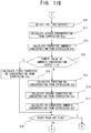
- the CPU 61 operates the heater circuit 57 to thereby cause the heater 21 to generate heat (step S1). After that, the CPU 61 performs initialization processing, whereby various values of the ammonia concentration output, the lowest value of the ammonia concentration output, and a read-out flag stored in the RAM 62 are reset (step S2).
- the read-out flag which represents whether or not the lowest value of the ammonia concentration output has been read out, is set to an unestablished state.
- the CPU 61 determines whether or not the sensor has been heated to an activation temperature by the heater 21 (step S3). In general, this determination is made by means of monitoring the electric resistance of the second solid electrolyte body 4a of the second pumping cell 4.
- the CPU 61 repeats the processing of step S3 until the heater 21 reaches the activation temperature.
- the CPU 61 detects the ammonia concentration output on the basis of the voltage between the above-mentioned paired electrodes 42a (step S4).
- the ammonia concentration output is electromotive force (EMF).
- the CPU 61 determines whether or not the read-out flag is 0 (step S5).
- the CPU 61 makes a "Yes" determination in step S5
- it stores the value of the ammonia concentration output in the RAM 62 (step S6).
- the CPU 61 determines whether or not the ammonia concentration output has increased by a predetermined value or more (step S7).
- the determination as to whether or not the ammonia concentration output has increased by a predetermined value or more is made by subtracting the last value of the ammonia concentration output from the value of the ammonia concentration output acquired this time, and determining whether or not a resultant value is equal to or greater than a predetermined value (determined, in consideration of variation, from a value calculated when the ammonia concentration has increased clearly).
- a predetermined value determined, in consideration of variation, from a value calculated when the ammonia concentration has increased clearly.
- step S7 the CPU 61 determines that a predetermined period of time has elapsed after the stoppage of injection of aqueous urea, and extracts the ammonia concentration output at the time when the ammonia concentration of the gas under measurement is 0; i.e., the lowest value of the values of the ammonia gas concentration output stored in the RAM 62 (step S8). Subsequently, the CPU 61 sets the read-out flag to 1 (step S9), and returns to step S4.
- step S5 when the CPU 61 makes a "No" determination in step S5, the CPU 61 detects the first pumping current Ip1 flowing through the first pumping cell 2, and the second pumping current Ip2 flowing through the second pumping cell 4 (step S10).
- the CPU 61 calculates the oxygen concentration on the basis of the above-described first pumping current Ip1 and the relational expression 63a (step S11). Moreover, the CPU 61 calculates the corrected ammonia concentration on the basis of the oxygen concentration calculated in step S8 and the relational expression 63b (step S12).
- the CPU 61 determines whether or not the ammonia concentration output of the ammonia sensor section 42 at the "time when the ammonia concentration of the gas under measurement is set to 0" is 0 (step S13). Specifically, the CPU 61 determines whether or not the lowest value of the ammonia gas concentration output extracted in step S8 is 0. When the CPU 61 makes a "Yes" determination in step S13, the CPU 61 refers to the relational expression 63c corresponding to the corrected ammonia concentration calculated in step S10, and calculates the first corrected NO concentration on the basis of the referred relational expression 63c and the Ip2 detected in step S6 (step S15).
- step S13 the gas under measurement is assumed not to contain NO 2 . Accordingly, the corrected ammonia concentration calculated in step S12 and the above-mentioned first NO concentration are employed as final values of the gas components of the gas under measurement.
- step S13 the CPU 61 calculates the expected NO 2 concentration on the basis of the ammonia concentration output of the ammonia sensor section 42 and the relational expression 63d (step S14). That is, in this case, since the gas under measurement contains NO and NO 2 , both the NO concentration and the NO 2 concentration must be obtained.
- step S16 the CPU 61 first estimates the NO 2 -attributable fraction from the expected NO 2 concentration calculated in step S14 and the relational expression 63e. Subsequently, the CPU 61 subtracts the NO 2 -attributable fraction from the Ip2 (original output) detected in step S10, to thereby calculate the NO-attributable fraction. Moreover, the CPU 61 calculates the second corrected NO concentration from the obtained NO-attributable fraction and the relational expression 63e.
- the gas under measurement contains NO and NO 2 . Therefore, the corrected ammonia concentration calculated in step S12, the above-mentioned expected NO 2 concentration, and the above-mentioned second corrected NO concentration can be employed as the final values of the gas components of the gas under measurement.
- the CPU 61 may refer to the relational expression 63f corresponding to the oxygen concentration calculated in step S11, and calculate the re-corrected ammonia concentration on the basis of the referred relational expression 63f and the expected NO 2 concentration calculated in step S14 (step S17).
- step S17 in place of the corrected ammonia concentration calculated in step S12, the re-corrected ammonia concentration calculated in step S17 is employed.
- the CPU 61 then outputs to the ECU 400 the gas concentrations calculated in the respective steps. After that, the CPU 61 determines whether to reset the read-out flag (step S18). That is, the CPU 61 determines whether to replace the lowest value of the ammonia concentration output extracted in step S8 with the lowest value of the ammonia concentration output obtained for the second time, immediately before the predetermined period of time elapses for the second time after the stoppage of injection of aqueous urea. When the CPU 61 makes a "No" determination in step S18, the CPU 61 repeats steps S4, S5, and S10 to S18. When the CPU 61 makes a "Yes" determination in step S18, the CPU 61 repeats steps S1 to S18.
- the CPU 61 which performs the processing of steps S4 to S18, corresponds to the "control means" in claims.
- the control method in the microcomputer 60 has been descried.
- the entirety or a portion of the present control can be performed in the ECU 400.
- the NO X sensor section 30A and the ammonia sensor section 42 are provided in the single multi-gas sensor 200A, and are placed under measurement environments which are substantially identical with each other (in terms of the composition, concentration, temperature, flow rate, pressure, etc. of the gas under measurement). Therefore, there is suppressed a drop in gas detection accuracy, which drop would otherwise occur due to a difference in measurement environment.
- the NO X sensor section 30A and the ammonia sensor section 42 on the single multi-gas sensor 200A the NO X (NO and NO 2 ) concentrations and the ammonia concentration can be measured simultaneously without being affected by the measurement environment, whereby the accuracy in detecting the NO X concentration and the ammonia concentration is improved. Also, since the gas under measurement comes into contact with the single multi-gas sensor 200A, NO X and ammonia can be detected substantially simultaneously, whereby a drop in detection accuracy stemming from a time lag between the detection of NO X and the detection of ammonia can be suppressed.
- the cost and size of the sensor of the present invention can be reduced, as compared with the case where the NO X sensor section 30A and the ammonia sensor section 42 are separate sensors.
- the multi-gas sensor 200A of the present invention can be used, for example, for detection of deterioration of catalyst provided as an auxiliary device of an engine apparatus main body, optimization of the urea injection amount in a urea SCR system, and accurate measurement of gas components (NO X , ammonia) on the downstream side of the catalyst.
- NO X gas components
- ammonia gas components
- these phenomena can be distinguished from one another.
- the multi-gas sensor 200A of the present invention can be manufactured in a manner similar to the manner of manufacture of known NO X sensors and ammonia sensors.
- the solid electrolyte bodies of the NO X sensor section are formed from a green sheet, and respective electrodes, leads, and insulating layers are formed through paste printing, whereby a green body of the NO X sensor section is formed.
- a green body of the ammonia sensor section is formed on the surface of the green body of the NO X sensor section at a predetermined position.
- the green body of the ammonia sensor section can be formed through paste printing of the electrodes, leads, sensitive portion, solid electrolyte body, diffusion layer, etc. of the sensor section.
- the green body of the NO X sensor section with the green body of the ammonia sensor section formed on the surface thereof is fired at a predetermined temperature, whereby the sensor element section of the multi-gas sensor is manufactured.
- the manufactured sensor element section is assembled to the housing, whereby the multi-gas sensor can be obtained.
- the present invention is not limited to the above-described embodiment, and, needless to say, the present invention encompasses various modifications and equivalents which fall within the scope of the present invention.
- the number of solid electrolyte bodies (layers) which constitute the NO X sensor section 30A is three; however, the number of the solid electrolyte bodies (layers) may be two.
- the element structure of an NO X sensor section formed by two solid electrolyte bodies (layers) is described in Japanese Patent Application Laid-Open ( kokai ) No. 2004-354400 ( FIG. 3 ).
- the second measurement chamber S2 is defined between the solid electrolyte bodies 2a and 6a in FIG. 2 , and the first measurement chamber S1 and the second measurement chamber S2 is separated from each other by the second diffusion resistor 8b.
- the inner second pumping electrode 4b is disposed on the upper surface of the solid electrolyte body 6. A portion of the lower surface of the solid electrolyte body 6 is exposed to the outside, and the second pumping counter electrode 4c is disposed on the exposed portion of the lower surface.
- step S13 is performed after the corrected ammonia concentration is calculated from the relational expression 63b (step S12). However, the determination of step S13 may be performed before step S12.
- step S13 when a "No" determination is made in step S13, ammonia concentration is calculated in step S17 without performance of step S12. Therefore, it becomes unnecessary to uselessly execute the processing of step S12. Needless to say, when a "Yes" determination is made in step S13, the processing of step S12 is performed.
- the multi-gas sensor 200A according to the above-described embodiment was manufactured.
- the selective reaction layer 42b was formed of BiVO 4 . Further, a porous layer of spinel (MgAl 2 O 4 ) was formed as the diffusion layer 44B covering the paired electrodes 42a and the selective reaction layer 42b.
- the value of Ip1 was measured in advance within a plurality of gases having known different O 2 concentrations, and the relational expression 63a, which is the first-order expression, was prepared. Similarly, the value of EMF corresponding to each of known different ammonia concentrations was obtained within a plurality of gases having known different O 2 concentrations, whereby the relational expression 63b shown in FIG. 5 was prepared.
- the gas temperature was set to 280°C, the gas flow rate was set to 5 m/s, the controlled temperature at the center between the paired electrodes of the ammonia sensor section 42 was set to 650°C.
- the multi-gas sensor was disposed in a gas flow of the model gas generator, and the first pumping current (Ip1) of the first pumping cell 2 and the ammonia concentration output (EMF) of the ammonia sensor section 42 were detected, while the O 2 concentration of the gas flow was changed to 1%, 5%, and 10%.
- the O 2 concentration of the model gas was calculated on the basis of the relational expression 63a and the Ip1.
- the calculated O 2 concentration was 1%, 5%, and 10%, which are equal to the concentrations of O 2 introduced into the base gas.
- Table 1 shows that, in the case of Example 1 in which the ammonia concentration was calculated in consideration of the O 2 concentration of the model gas, the ammonia concentration was able to be calculated accurately without being affected by the O 2 concentration.
- the ammonia concentration was set to 0, and a negative value of EMF was measured in advance in a plurality of gases having known different NO 2 concentrations, whereby the relational expression 63d shown in FIG. 8 was prepared. Also, a value of Ip2 (NO 2 -attributable fraction) was obtained in a plurality of gases containing NO 2 only and having known different NO 2 concentrations. Similarly, a value of Ip2 (NO-attributable fraction) was obtained in a plurality of gases containing NO only and having known different NO concentrations. Through these procedures, the relational expression 63e shown in FIG. 9 was prepared.
- the NO 2 concentration of a gas having a known constant O 2 concentration was set to a predetermined value, and values of the EMF corresponding to known ammonia concentrations were obtained. This procedure was repeated for various NO 2 concentrations, whereby the relational expression 63f shown in FIG. 10 was prepared. Also, the relational expression 63f was similarly prepared while the O 2 concentration was changed. Finally, the relational expression 63f representing values of the EMF corresponding to various ammonia concentrations for each combination between different O 2 concentrations and different NO 2 concentrations was obtained.
- the senor was disposed in a gas flow of the model gas generator under the same conditions as those mentioned in the section 2-1, except for the gas composition.
- the detected EMF was -19 mV.
- the expected NO 2 concentration calculated from this value of EMF by use of the relational expression 63d of FIG. 8 was 40 ppm.
- the NO 2 -attributable fraction estimated by use of the expected NO 2 concentration and the relational expression 63e of FIG. 9 was 0.084 ⁇ A.
- the second pumping current (Ip2) of the second pumping cell 4 detected in this base gas was 0.15 ⁇ A.
- the NO-attributable fraction was estimated to be 0.066 ⁇ A (0.15 - 0.084).
- the NO concentration calculated from this NO-attributable fraction and the relational expression 63e was 22.9 ppm.
- the sensor was attached to the model gas generator mentioned in the above-described paragraph 2-2, and the EMF was detected in the above-described gas.
- the detected EMF was 64.7 mV.
- the calculated ammonia concentration was 50.1 ppm.
- the NO concentration and the NO 2 concentration were able to be calculated separately.
- separation of NO and NO 2 is difficult.
- NO and NO 2 differ in molecular size. Therefore, even in the case where the Ip2 output of the NO X sensor is the same, the calculated NO X concentration may change in accordance with the ratio between NO and NO 2 in the gas under measurement.
- the NO concentration and the NO 2 concentration were able to be calculated separately and accurately.
- the Ip2 was detected in a state in which the sensor was placed in the above-mentioned gas, and the NO concentration was calculated by use of the relational expression 63c shown in FIG. 6 .
- the results are shown in Table 2.
- the NH 3 concentration of the base gas was changed to 0 ppm, 20 ppm, 60 ppm, and 100 ppm, and, of the relational expressions 63c shown in FIG. 6 , a first-order expression corresponding to the ammonia concentration was used.
- Table 2 shows that, in the case of Example 2 in which the NO concentration was calculated in consideration of the ammonia concentration of the model gas, the NO concentration was able to be calculated accurately without being affected by the ammonia concentration.
Description
- The present invention relates to a method and apparatus for controlling a multi-gas sensor suitable for detection of the nitrogen oxide concentration and ammonia concentration of a gas under measurement.
- As gas sensors for measuring the concentration of a specific gas contained in exhaust gas of an automobile, there have been known an NOX sensor which uses a solid electrolyte body so as to detect the NOX concentration of a gas under measurement, and an ammonia sensor which detects the ammonia concentration of a the gas under measurement by making use of a change in impedance between a pair of electrodes or a change in electromotive force generated therebetween.
- Also, there has been proposed a technique for simultaneously measuring the NOX concentration and ammonia concentration of a gas under measurement. The proposed technique has a step in which the gas under measurement is brought into contact with NH3 strong oxidizing catalyst so as to convert ammonia to NOX, and the overall NOX concentration is measured; and a step in which the gas under measurement is brought into contact with NH3 weak oxidizing catalyst so as to convert a portion of ammonia to NOX, and the NOX concentration is measured. The NOX concentration and the ammonia concentration are calculated from two detection values obtained in these steps (see Patent Document 1).
- Furthermore, there has been proposed an ammonia sensor in which an NOX electrode, a reference electrode, a selection electrode, and an ammonia electrode are provided in the single sensor to thereby form a plurality of cells. A method of calculating ammonia concentration is changed in accordance with an electromotive force generated between the NOX electrode and the reference electrode as a result of introduction of a gas (in accordance with the state of presence of NOX), whereby the ammonia concentration is measured accurately (see Patent Document 2). Specifically, in accordance with the state of presence of NOX, an electromotive force between the ammonia electrode and the reference electrode or an electromotive force between the NOX electrode and the ammonia electrode is selectively used for detection.
-
- [Patent Document 1] Japanese Patent Application Laid-Open (kokai) No.
2001-133447 - [Patent Document 2] Japanese Kohyo (
PCT) Patent Publication No. 2009-511859 - However, in the case of the technique described in
Patent Document 1, since measurement is performed on the basis of a difference in catalytic performance, if the catalytic performance changes due to changes in measurement conditions (temperature, flow rate, pressure, etc.), accurate measurement cannot be performed. Moreover, in the case where the apparatus disposed inPatent Document 1 is disposed in a severe environment such as in exhaust gas of an automobile, it is difficult to stably maintain the catalytic performance over a long period of time. - Also, the technique which is described in
Patent Document 2 and in which the detection electrodes to be used for measurement of ammonia concentration are switched has the following problem. When the measurement environment changes, initially set conditions for switching the detection electrodes (setting of switching timing, reference output point, etc.) must be changed, and accurate measurement of ammonia concentration becomes rather difficult. Furthermore, complicate control; i.e., switching of the detection electrodes, is needed. - Furthermore, in the case where a plurality of gas concentrations are measured by use of separate sensors, the following problem occurs. Since the sensors are not provided at the same location, gas concentration, temperature distribution, etc. vary among the sensors, and measurement delay occurs in a certain sensor(s). The variation and delay may adversely affect the measurement.
- Moreover, oxygen concentration may influence the measurement of ammonia concentration performed by use of an ammonia sensor; however, conventional ammonia sensors encounter difficulty in performing measurement in consideration of the influence of oxygen concentration.
- Accordingly, an object of the present invention is to provide a method and apparatus for controlling a multi-gas sensor which can measure NOX concentration and ammonia concentration by use of a single gas sensor and can improve accuracy in measurement of ammonia concentration.
- To solve the above-described problems, the present invention provides a method for controlling a multi-gas sensor comprising an NOX sensor section; and an ammonia sensor section formed on an outer surface of the NOX sensor section, wherein the NOX sensor section includes a first pumping cell which extends between the interior and exterior of a first measurement chamber, has paired first electrodes provided on a first solid electrolyte body, and is adapted to pump out or pump in oxygen of a gas under measurement introduced into the first measurement chamber, and a second pumping cell which extends between the interior and exterior of an NOX measurement chamber communicating with the first measurement chamber, has paired second electrodes provided on a second solid electrolyte body), and is configured such that a second pumping current flows between the paired second electrodes, the second pumping current corresponding to an NOX concentration of the gas under measurement having flowed into the NOX measurement chamber after adjustment of its oxygen concentration in the first measurement chamber; and the ammonia sensor section has at least a pair of electrodes formed on a solid electrolyte body and outputs an ammonia concentration output. The method comprises calculating an oxygen concentration on the basis of a first pumping current flowing through the first pumping cell; and calculating a corrected ammonia concentration on the basis of the oxygen concentration and the ammonia concentration output of the ammonia sensor section.
- According to this method, the ammonia concentration can be accurately calculated without being affected by the oxygen concentration of the gas under measurement.
- Furthermore, even in a severe environment, such as in exhaust gas of an automobile, the ammonia concentration can be calculated stably over a long period of time.
- Moreover, since the NOX sensor section and the ammonia sensor section are located at the same position, the sensor sections are placed under the same conditions (gas concentration, temperature distribution, etc.), whereby a measurement delay occurring in a certain sensor(s) can be suppressed.
- The method for controlling a multi-gas sensor of the present invention may be such that, in the case where the ammonia concentration output of the ammonia sensor section becomes 0 as a result of the ammonia concentration of the gas under measurement being set to 0, a first corrected NO concentration is calculated on the basis of the corrected ammonia concentration and the second pumping current.
- In the case where the gas under measurement contains ammonia gas and NOX gas (NO, NO2), the second pumping current corresponding to the NOX concentration is affected by the ammonia concentration. However, by virtue of the present method, the NOX concentration can be detected accurately without being affected by the concentration of the ammonia gas.
- Notably, this method is used when the gas under measurement does not contain NO2, and the NO concentration can be calculated accurately without being affected by the ammonia concentration of the gas under measurement.
- An example of the "time when the ammonia concentration of the gas under measurement is set to 0" is a time when a predetermined period of time elapses after the stoppage of injection of aqueous urea into the gas under measurement.
- A phenomenon that the ammonia concentration becomes 0 at that timing is utilized, and the above-described method is used in the case where, when the ammonia concentration is measured by the ammonia sensor section exposed to the gas under measurement, the ammonia concentration output becomes 0 at that timing.
- The method for controlling a multi-gas sensor of the present invention may be such that, in the case where the ammonia concentration output of the ammonia sensor section becomes negative as a result of the ammonia concentration of the gas under measurement being set to 0, an expected NO2 concentration is calculated in advance on the basis of the negative ammonia concentration output, and a second corrected NO concentration is calculated on the basis of the second pumping current and the expected NO2 concentration.
- In the case where the gas under measurement contains ammonia gas and NOX gas (NO, NO2), the second pumping current corresponding to the NOX concentration is affected by the ammonia concentration. However, by virtue of the present method, the NOX concentration can be detected accurately without being affected by the concentration of the ammonia gas.
- Notably, this method is used when the gas under measurement contains NO2, and, even in the case where NO and NO2 coexist in the gas under measurement, the NO concentration and the NO2 concentration can be calculated separately and accurately. In contrast, in conventional NOX sensors, separation of NO and NO2 is difficult. In addition, NO and NO2 differ in molecular size. Therefore, even in the case where the above-mentioned second pumping current of the NOX sensor is the same, the calculated NOX concentration may change in accordance with the ratio between NO and NO2 in the gas under measurement.
- An example of the "time when the ammonia concentration of the gas under measurement is set to 0" is a time when a predetermined period of time elapses after the stoppage of injection of aqueous urea into the gas under measurement. A phenomenon that the ammonia concentration becomes 0 at that timing is utilized, and the above-described method is used in the case where, when the ammonia concentration is measured by the ammonia sensor section exposed to the gas under measurement, the ammonia concentration output becomes negative at that timing.
- In the method for controlling a multi-gas sensor of the present invention, the corrected ammonia concentration may be calculated on the basis of the expected NO2 concentration as well as the oxygen concentration.
- According to this method, the ammonia concentration is calculated in consideration of not only the oxygen concentration but also the NO2 concentration. Therefore, the accuracy is further improved as compared with the case where the ammonia concentration is calculated in consideration of the oxygen concentration only.
- The present invention also provides an apparatus for controlling a multi-gas sensor comprising an NOX sensor section; and an ammonia sensor section formed on an outer surface of the NOX sensor section, wherein the NOX sensor section includes a first pumping cell which extends between the interior and exterior of a first measurement chamber, has paired first electrodes provided on a first solid electrolyte body, and is adapted to pump out or pump in oxygen of a gas under measurement introduced into the first measurement chamber, and a second pumping cell which extends between the interior and exterior of an NOX measurement chamber communicating with the first measurement chamber, has paired second electrodes provided on a second solid electrolyte body, and is configured such that a second pumping current flows between the paired second electrodes, the second pumping current corresponding to an NOX concentration of the gas under measurement having flowed into the NOX measurement chamber after adjustment of its oxygen concentration in the first measurement chamber; and the ammonia sensor section has at least a pair of electrodes formed on a solid electrolyte body and outputs an ammonia concentration output. The apparatus comprises control means for calculating an oxygen concentration on the basis of a first pumping current flowing through the first pumping cell, and for calculating a corrected ammonia concentration on the basis of the oxygen concentration and the ammonia concentration output of the ammonia sensor section.
- According to this apparatus, the ammonia concentration can be accurately calculated without being affected by the oxygen concentration of the gas under measurement.
- Furthermore, even in a severe environment, such as in exhaust gas of an automobile, the ammonia concentration can be calculated stably over a long period of time.
- Moreover, since the NOX sensor section and the ammonia sensor section are located at the same position, the sensor sections are placed under the same conditions (gas concentration, temperature distribution, etc.), whereby a measurement delay occurring in a certain sensor(s) can be suppressed.
- According to the present invention, it becomes possible to measure NOX concentration and ammonia concentration by use of a single gas sensor, and to improve accuracy in measurement of ammonia concentration.
-
- [
FIG. 1 ] Longitudinal sectional view of a multi-gas sensor according to an embodiment of the present invention. - [
FIG. 2 ] Block diagram showing the configuration of the multi-gas sensor and a gas sensor control apparatus according to the embodiment of the present invention. - [
FIG. 3 ] Exploded view showing the configuration of an ammonia sensor section. - [
FIG. 4 ] Block diagram showing the configurations of various data stored in the gas sensor control apparatus (a microcomputer thereof). - [
FIG. 5 ] Graph showing an example expression representing the relation between ammonia concentration output and ammonia concentration. - [
FIG. 6 ] Graph showing an example expression representing the relation between second pumping current and NO concentration. - [
FIG. 7 ] Graph showing the relation between ammonia concentration output and ammonia concentration for various NO concentrations. - [
FIG. 8 ] Graph showing an example expression representing the relation between negative ammonia concentration output and NO2 concentration. - [
FIG. 9 ] Graph showing an example expression representing the relation between fractional second pumping current, and NO concentration and NO2 concentration. - [
FIG. 10 ] Graph showing an example expression representing the relation between ammonia concentration output and ammonia concentration at a certain oxygen concentration for various NO2 concentrations. - [
FIG. 11 ] Charts showing the flow of processing performed by the gas sensor control apparatus (the microcomputer thereof) so as to calculate ammonia concentration and concentrations of other gas components. - An embodiment of the present invention will now be described.
-
FIG. 1 shows a longitudinal cross section of amulti-gas sensor 200A, which is an example sensor to be controlled by a control method according to the embodiment of the present invention. Themulti-gas sensor 200A is an assembly including a multi-gassensor element section 100A for detecting ammonia concentration and NOX concentration. Themulti-gas sensor 200A includes the plate-shaped multi-gassensor element section 100A extending in an axial direction; a tubularmetallic shell 138 having ascrew portion 139 formed on an outer surface thereof for fixation to an exhaust pipe; a tubularceramic sleeve 106 disposed to surround the circumference of the multi-gassensor element section 100A; an insulatingcontact member 166 disposed such that the inner wall surface of acontact insertion hole 168 axially extending through the insulatingcontact member 166 surrounds the circumference of a rear end portion of the multi-gassensor element section 100A; and a plurality of connection terminals 110 (inFIG. 1 , only two connection terminals are illustrated) disposed between the multi-gassensor element section 100A and the insulatingcontact member 166. - The
metallic shell 138, which is formed into a generally tubular shape, has a throughhole 154 axially extending through themetallic shell 138, and aledge portion 152 projecting radially inward from the wall surface of the throughhole 154. Themetallic shell 138 holds the multi-gassensor element section 100A in the throughhole 154 such that a front end portion of the multi-gassensor element section 100A is located frontward of the front end of the throughhole 154, andelectrode terminal portions hole 154. Theledge portion 152 has an inward taper surface which inclines in relation to a plane perpendicular to the axial direction. - A
ceramic holder 151, powder layers 153 and 156 (hereinafter may be referred to as "talc rings 153 and 156"), and the above-mentionedceramic sleeve 106 are stacked in the throughhole 154 of themetallic shell 138, in this sequence from the front end side toward the rear end side, so that they surround the circumference of the multi-gassensor element section 100A. A crimping packing 157 is disposed between theceramic sleeve 106 and arear end portion 140 of themetallic shell 138. Ametallic holder 158 for holding thetalc ring 153 and theceramic holder 151 and for maintaining airtightness is disposed between theceramic holder 151 and theledge portion 152 of themetallic shell 138. Notably, therear end portion 140 of themetallic shell 138 is crimpled such that therear end portion 140 presses theceramic sleeve 106 frontward via the crimpingpacking 157. - Meanwhile, as shown in
FIG. 1 , anouter protector 142 and aninner protector 143, which are formed of metal (e.g., stainless steel) and form a double protector, are attached to the outer circumference of a front end portion (a lower end portion inFIG. 1 ) of themetallic shell 138 by means of, for example, welding. Theouter protector 142 and theinner protector 143 cover a projecting portion of the multi-gassensor element section 100A, and each have a plurality of holes. - An
outer sleeve 144 is fixed to the outer circumference of a rear end portion of themetallic shell 138. Agrommet 150 is disposed in an opening of theouter sleeve 144 located on the rear end side (on the upper side inFIG. 1 ) thereof. Thegrommet 150 has lead wire insertion holes 161, through which a plurality of lead wires 146 (only three of them are shown inFIG. 1 ) are inserted to be electrically connected to theelectrode terminal portions sensor element section 100A. Notably, inFIG. 1 , in order to simplify the drawing, electrode terminal portions on the front surface of the multi-gassensor element section 100A and those on the back surface thereof are represented by theelectrode terminal portions ammonia sensor section 42, which will be described later. - The insulating
contact member 166 is disposed at a rear end portion (an upper end portion inFIG. 1 ) of the multi-gassensor element section 100A projecting from therear end portion 140 of themetallic shell 138. The insulatingcontact member 166 is disposed to surround theelectrode terminal portions sensor element section 100A. The insulatingcontact member 166, which is formed into a tubular shape, has acontact insertion hole 168 axially extending through the insulatingcontact member 166, and aflange portion 167 projecting radially outward from an outer surface thereof. The insulatingcontact member 166 is disposed inside theouter sleeve 144 with itsflange portion 167 being in contact with theouter sleeve 144 via a holdingmember 169. Theconnection terminals 110 disposed in the insulatingcontact member 166 are electrically connected to theelectrode terminal portions sensor element section 100A, and electrically communicate with an external device via thelead wires 146. -
FIG. 2 is a block diagram showing the configuration of a multi-gas sensor control apparatus (controller) 300 according to the embodiment of the present invention, and the configuration of the multi-gassensor element section 100A connected thereto. Notably, in order to facilitate description,FIG. 2 shows only a longitudinal cross section of the multi-gassensor element section 100A accommodated within themulti-gas sensor 200A. - The
multi-gas sensor 200A (the multi-gassensor element section 100A) and the multi-gassensor control apparatus 300 are mounted on an unillustrated vehicle having an internal combustion engine (hereinafter may be referred to as the "engine"), and the multi-gassensor control apparatus 300 is electrically connected to a vehicle-side control apparatus (hereinafter may be referred to as "ECU") 400. Notably, ends of thelead wires 146 extending from themulti-gas sensor 200A are connected to a connector, which is electrically connected to a connector of the multi-gassensor control apparatus 300. - The
ECU 400 receives data representing the ammonia concentration and NOX concentration of exhaust gas calculated by the multi-gassensor control apparatus 300, and executes various types of processing on the basis of the received data so as to control the operation status of the engine or remove NOX accumulated in a catalyst unit. - Next, the configuration of the multi-gas
sensor element section 100A will be described. The multi-gassensor element section 100A includes the NOX sensor section 30A having a configuration similar to that of a known NOX sensor, and theammonia sensor section 42 having a configuration similar to that of a known ammonia sensor. As will be described in detail later, theammonia sensor section 42 is formed on the outer surface of the NOX sensor section 30A. - The NOX sensor section 30A includes insulating
layers 23f, asolid electrolyte body 25 for the ammonia sensor section, an insulatinglayer 23e, a firstsolid electrolyte body 2a, an insulatinglayer 23d, a thirdsolid electrolyte body 6a, an insulatinglayer 23c, a secondsolid electrolyte body 4a, and insulatinglayers solid electrolyte body 2a and the thirdsolid electrolyte body 6a. A gas under measurement is externally introduced into the first measurement chamber S1 via afirst diffusion resistor 8a disposed at the left end (inlet) of the first measurement chamber S1. Notably, aprotection layer 9 formed of a porous material is disposed on the outer side of thefirst diffusion resistor 8a. - A
second diffusion resistor 8b is disposed at the end of the first measurement chamber S1 opposite the inlet. A second measurement chamber (corresponding to the "NOX measurement chamber" of the present invention) S2 is defined on the right side of the first measurement chamber S1, and communicates with the first measurement chamber S1 via thesecond diffusion resistor 8b. The second measurement chamber S2 is formed between the firstsolid electrolyte body 2a and the secondsolid electrolyte body 4a such that the second measurement chamber S2 penetrates the thirdsolid electrolyte body 6a. - An elongated plate-shaped
heater 21 is embedded between the insulatinglayers heater 21 extends along the longitudinal direction of the multi-gassensor element section 100A. Theheater 21 is used so as to heat the gas sensor to an activation temperature and enhance the oxygen ion conductivity of the solid electrolyte body, to thereby stabilize operation. - Each of the insulating
layers first diffusion resistor 8a and thesecond diffusion resistor 8b is formed of a porous material such as alumina. Theheater 21 is formed of platinum or the like. - A
first pumping cell 2 includes a firstsolid electrolyte body 2a mainly formed of zirconia having oxygen ion conductivity; and inner and outer (counter)first pumping electrodes solid electrolyte body 2a. The innerfirst pumping electrode 2b faces the first measurement chamber S1. Each of the inner and outerfirst pumping electrodes first pumping electrode 2b is covered with a protection layer 11 formed of a porous material. - A portion of the insulating
layer 23e corresponding to the upper surface of the outerfirst pumping electrode 2c is removed so as to form an opening, and the opening is filled with aporous material 13. Thus, communication is established between the outerfirst pumping electrode 2c and the exterior of the sensor element section, whereby entry and exit of gas (oxygen) is permitted. - An oxygen concentration detection cell 6 includes a third
solid electrolyte body 6a mainly formed of zirconia; and adetection electrode 6b and areference electrode 6c disposed to sandwich the thirdsolid electrolyte body 6a. Thedetection electrode 6b faces the first measurement chamber S1 at a position downstream of the innerfirst pumping electrode 2b. Each of thedetection electrode 6b and thereference electrode 6c is mainly formed of platinum. - Notably, the insulating
layer 23c is partially removed so as to from an opening such that thereference electrode 6c in contact with the thirdsolid electrolyte body 6a is disposed in the opening. The opening is filled with a porous material, and forms areference oxygen chamber 15. When a very weak constant current is supplied to the oxygen concentration detection cell 6 by use of anIcp supply circuit 54, the oxygen concentration detection cell 6 feeds oxygen from the first measurement chamber S1 to thereference oxygen chamber 15, to thereby establish an oxygen reference. - A second pumping cell 4 includes a second
solid electrolyte body 4a mainly formed of zirconia; and an innersecond pumping electrode 4b and a secondpumping counter electrode 4c (corresponding to the "second electrodes" in claims) disposed on the surface of the secondsolid electrolyte body 4a facing the second measurement chamber S2. Each of the insidesecond pumping electrode 4b and the secondpumping counter electrode 4c is mainly formed of platinum. - Notably, the second
pumping counter electrode 4c is disposed on the secondsolid electrolyte body 4a to be located in the opening of the insulatinglayer 23c. Therefore, the secondpumping counter electrode 4c faces thereference electrode 6c via thereference oxygen chamber 15. - The inner
first pumping electrode 2b, thedetection electrode 6b, and the innersecond pumping electrode 4b are connected to a reference potential. - The
ammonia sensor section 42 is formed on the insulatinglayers 23f, which form the outer surface of the NOX sensor section 30A. However, the insulatinglayers 23f are partially removed such that thesolid electrolyte body 25 for the ammonia sensor section is exposed; and a pair ofelectrodes 42a of theammonia sensor section 42 are formed on the exposed portion. More specifically, theammonia sensor section 42 includes the pair ofelectrodes 42a formed on thesolid electrolyte body 25 for the ammonia sensor section, and aselective reaction layer 42b which covers the pair ofelectrodes 42a. Theammonia sensor section 42 detects the ammonia concentration of the gas under measurement from a change in electromotive force between the pair ofelectrodes 42a. - A
diffusion layer 44B formed of a porous material is formed so as to completely cover theselective reaction layer 42b. Thediffusion layer 44B can adjust the diffusion speed of the gas under measurement which flows into theammonia sensor section 42 from the outside of the sensor element section. -
FIG. 3 is an exploded view showing the configuration of theammonia sensor section 42. Paired electrodes 42a1 and 42a2 (the pair ofelectrodes 42a) are disposed on thesolid electrolyte body 25 for the ammonia sensor section. Leads 42ax and 42ay extend from the electrodes 42a1 and 42a2 along the longitudinal direction of thesolid electrolyte body 25 for the ammonia sensor section. The upper and lower sides of the leads 42ax and 42ay are covered with the insulatinglayers 23f. Right end portions of the leads 42ax and 42ay are not covered with the insulatinglayers 23f and are exposed to the outside to thereby form predetermined electrode terminal portions. - The electrodes 42a1 and 42a2 are juxtaposed and spaced from each other along the lateral direction of the
solid electrolyte body 25 for the ammonia sensor section. The electrode 42a1 is formed of a material whose main component is gold, and functions as a detection electrode. The electrode 42a2 is formed of a material whose main component is platinum, and functions as a reference electrode. Since the detection electrode 42a1 is higher than the reference electrode 42a2 in terms of reactivity with ammonia, electromotive force is produced between the detection electrode 42a1 and the reference electrode 42a2. - The
solid electrolyte body 25 for the ammonia sensor section is formed of an oxygen-ion-conductive material such as ZrO2. The leads 42ax and 42ay are formed of, for example, a material whose main component is platinum. - The
selective reaction layer 42b has a function of burning combustible gas components of the gas under measurement, other than ammonia. When theselective reaction layer 42b is present, ammonia contained in the gas under measurement can be detected without being affected by the combustible gas components. Theselective reaction layer 42b generally includes a metal oxide as a main component, and is preferably formed from a material (e.g., bismuth vanadium oxide: BiVO4) which contains vanadium oxide (V2O5) and bismuth oxide (Bi2O3) in predetermined proportions. - Notably, the above-described effect can be attained even when the
selective reaction layer 42b covers the detection electrode 42a1 only. In the present embodiment, the detection electrode 42a1 and theselective reaction layer 42b are provided separately. However, the embodiment may be modified such that theselective reaction layer 42b is not provided, and a material (e.g., a metal oxide) which forms theselective reaction layer 42b is included in the detection electrode 42a1. - The
diffusion layer 44B is formed of, for example, at least one selected from the group consisting of alumina, spinel (MgAl2O4), silica alumina, and mullite. The diffusion time required for the gas to reach theselective reaction layer 42b and the electrodes 42a1 and 42a2 can be adjusted by means of properly adjusting the thickness, grain size, size distribution, porosity, compositional proportions, etc. of thediffusion layer 44B. - Notably, in the present embodiment, the position of the
ammonia sensor section 42 on the NOX sensor section 30A is determined such that, when the controlled temperature of the secondsolid electrolyte body 4a of the NOX sensor section 30A is set to 600°C, the temperature of theammonia sensor section 42 becomes 650°C. - Referring back to
FIG. 2 , an example configuration of the multi-gassensor control apparatus 300 will be described. The multi-gassensor control apparatus 300 includes an (analog)control circuit 59 and amicrocomputer 60 provided on a circuit board. Themicrocomputer 60, which controls the entire multi-gassensor control apparatus 300, includes a CPU (Central Processing Unit) 61, aRAM 62, aROM 63, a signal input/output section 64, an A/D converter 65, and an unillustrated clock. The CPU executes programs stored in the ROM, etc., in advance. - The
control circuit 59 includes a referencevoltage comparison circuit 51, anIp1 drive circuit 52, aVs detection circuit 53, anIcp supply circuit 54, anIp2 detection circuit 55, aVp2 application circuit 56, aheater drive circuit 57, and an ammonia sensor section electromotiveforce detection circuit 58, which will be described in detail later. - The
control circuit 59 controls the NOX sensor section 30A, detects first and second pumping currents Ip1 and Ip2 flowing through the NOX sensor section 30A, and outputs the detected first and second pumping currents Ip1 and Ip2 to themicrocomputer 60. - The ammonia sensor section electromotive
force detection circuit 58 detects an ammonia concentration output (electromotive force) between the paired electrodes 42a1 and 42a2, and outputs the detected ammonia concentration output to themicrocomputer 60. - Specifically, the outer
first pumping electrode 2c of the NOX sensor section 30A is connected to theIp1 drive circuit 52, and thereference electrode 6c is connected to theVs detection circuit 53 and theIcp supply circuit 54. The secondpumping counter electrode 4c is connected to theIp2 detection circuit 55 and theVp2 application circuit 56. Theheater circuit 57 is connected to theheater 21. - The paired electrodes 42a1 and 42a2 of the
ammonia sensor section 42 are connected to the ammonia sensor section electromotiveforce detection circuit 58. - The
circuits 51 to 57 have the following functions. - The
Ip1 drive circuit 52 supplies a first pumping current Ip1 which flows between the innerfirst pumping electrode 2b and the outerfirst pumping electrode 2c, and detects the first pumping current Ip1 at that time. - The
Vs detection circuit 53 detects a voltage Vs between thedetection electrode 6b and thereference electrode 6c, and outputs the detected voltage Vs to the referencevoltage comparison circuit 51. - The reference
voltage comparison circuit 51 compares a reference voltage (e.g., 425 mV) and the output (voltage Vs) of theVs detection circuit 53, and outputs a comparison result to theIp1 drive circuit 52. TheIp1 drive circuit 52 controls the flow direction and magnitude of the Ip1 current such that the voltage Vs becomes equal to the above-mentioned reference voltage, to thereby adjust the concentration of oxygen within the first measurement chamber S1 to a predetermined value at which NOX does not decompose. - The
Icp supply circuit 54 supplies a weak current Icp which flows between thedetection electrode 6b and thereference electrode 6c so as to pump oxygen from the first measurement chamber S1 into thereference oxygen chamber 15, to thereby expose thereference electrode 6c to oxygen of a predetermined concentration serving as a reference. - The
Vp2 application circuit 56 applies between the innersecond pumping electrode 4b and the secondpumping counter electrode 4c a constant voltage Vp2 (e.g., 450 mV) at which NOX gas in the gas under measurement decomposes to oxygen and N2 gas, to thereby decompose NOX to nitrogen and oxygen. - The
Ip2 detection circuit 55 detects a second pumping current Ip2 which flows through the second pumping cell 4 when oxygen produced as a result of decomposition of NOX is pumped from the second measurement chamber S2 toward the secondpumping counter electrode 4c via the secondsolid electrolyte body 4a. - The
Ip1 drive circuit 52 outputs the value of the detected first pumping current Ip1 to the A/D converter 65. Furthermore, theIp2 detection circuit 55 outputs the value of the detected second pumping current Ip2 to the A/D converter 65. - The A/
D converter 65 converts these values to corresponding digital values, and outputs the digital values to theCPU 61 via the signal input/output section 64. - Next, an example control performed by use of the
control circuit 59 will be described. First, when thecontrol circuit 59 receives electric power from an external power supply upon startup of the engine, theheater 21 operates via theheater circuit 57 so as to heat thefirst pumping cell 2, the oxygen concentration detection 6, and the second pumping cell 4 to an activation temperature. TheIcp supply circuit 54 supplies the weak current Icp which flows between thedetection electrode 6b and thereference electrode 6c so as to pump oxygen from the first measurement chamber S1 into thereference oxygen chamber 15, to thereby create the oxygen reference. - When the NOX sensor section 30A is heated to a proper temperature by the
heater 21, theammonia sensor section 42 on the NOX sensor section 30A is also heated to a desired temperature accordingly. - Once each cell has been heated to the activation temperature, the
first pumping cell 2 pumps, from the innerfirst pumping electrode 2b toward the outerfirst pumping electrode 2c, oxygen contained in the gas under measurement (exhaust gas) having flowed into the first measurement chamber S1. - At that time, the oxygen concentration within the first measurement chamber S1 corresponds to the inter-electrode voltage (inter-terminal voltage) Vs of the oxygen concentration detection cell 6. Therefore, the
Ip1 drive circuit 52 controls the first pumping current Ip1 flowing through thefirst pumping cell 2 such that the inter-electrode voltage Vs becomes equal to the above-mentioned reference voltage, to thereby adjust the oxygen concentration within the first measurement chamber S1 to a level at which NOX does not decompose. - The gas under measurement whose oxygen concentration has been adjusted flows toward the second measurement chamber S2. The
Vp2 application circuit 56 applies to the second pumping cell 4, as the inter-electrode voltage (inter-terminal voltage), a constant voltage Vp2 (voltage higher than the control voltage of the oxygen concentration detection cell 6; e.g., 450 mV) at which NOX gas in the gas under measurement decomposes into oxygen and N2 gas. Thus, NOX is decomposed into nitrogen and oxygen. Then, the second pumping current Ip2 flows through the second pumping cell 4 such that oxygen produced as a result of decomposition of NOX is pumped out from the second measurement chamber S2. Since a linear relation is present between the second pumping current Ip2 and the NOX concentration, the NOX concentration of the gas under measurement can be detected through detection of the second pumping current Ip2 by theIp2 detection circuit 55. Notably, in the present invention, when necessary, a determination as to whether or not NOX includes NO2 is made. Thus, the concentration of NO contained in NOX and the concentration of NOX can be calculated accurately and separately. Processing for calculating these concentrations will be described later. - Also, the ammonia sensor section electromotive
force detection circuit 58 can detect the ammonia concentration output (electromotive force) between the paired electrodes 42a1 and 42a2 to thereby detect the ammonia concentration of the gas under measurement. Notably, the NH3 concentration is calculated by use of an ammonia concentration conversion value which is stored in themicrocomputer 60 and which is determined on the basis of the electromotive force between the electrodes 42a1 and 42a2 (a rate of change (sensitivity) between a base electromotive force at the time when the ammonia concentration is 0 and an electromotive force at the time when ammonia is present may be used). Processing for calculating the NH3 concentration will be described later. - Next, the configurations of
various data sets 63a to 63f stored in the microcomputer 60 (ROM 63) of the multi-gassensor control apparatus 300 will be described with reference toFIG. 4 . Notably, the CPU (corresponding to the "control means" in claims) 61 reads thevarious data sets 63a to 63f, and executes processing for calculating various gas concentrations, such as ammonia concentration, as follows. - As shown in
FIG. 4 , theROM 63 stores anexpression 63a representing the relation between first pumping current (Ip1) and oxygen concentration; anexpression 63b representing the relation between ammonia concentration output (electromotive force EMF) and ammonia concentration for each of a plurality of oxygen concentrations; anexpression 63c representing the relation between second pumping current (Ip2) and NO concentration for each of a plurality of ammonia concentrations; anexpression 63d representing the relation between negative ammonia concentration output and NO2 concentration; anexpression 63e representing the relation between fractional second pumping current, and NO concentration and NO2 concentration; and anexpression 63f representing the relation between ammonia concentration output and ammonia concentration for each combination between a plurality of oxygen concentrations and a plurality of NO2 concentrations. - Notably, in the example of
FIG. 4 , each of thevarious data sets 63a to 63f represents a predetermined relational expression. However, each of thevarious data sets 63a to 63f may represent a table or the like so long as the table or the like enables calculation of various gas concentrations from the output of the sensor. Alternatively, each of thevarious data sets 63a to 63f may represent a relational expression, table, or the like which represents values obtained in advance by use of a model gas whose gas concentrations are known. - The
relational expression 63a represents the relation between the first pumping current (Ip1), which flows through thefirst pumping cell 2 as a result of pumping out or pumping in of oxygen of the gas under measurement introduced into the first measurement chamber, and the oxygen concentration of the gas under measurement. Although not illustrated, in general, a substantially linear relation is present between the Ip1 and the oxygen concentration. The oxygen concentration of the gas under measurement can be calculated on the basis of therelational expression 63a representing the relation between the first pumping current (Ip1) and the oxygen concentration. - The
relational expression 63b is set for each of a plurality of oxygen concentrations, and represents the relation between the ammonia concentration output of the ammonia sensor section and the ammonia concentration of the gas under measurement. -
FIG. 5 shows an example expression representing the relation between the ammonia concentration output and the ammonia concentration. In the present embodiment, for each of different oxygen concentrations, the ammonia concentration is represented by a third-order expression of EMF. EMF changes depending on oxygen concentration. However, since the ammonia concentration is determined from therelational expression 63b representing the relation between the ammonia concentration output and the ammonia concentration for each of a plurality of oxygen concentrations, an accurate value of the ammonia concentration (the "corrected ammonia concentration" in claims) which is not affected by the oxygen concentration of the gas under measurement can be calculated. - Notably, an expression representing the relation between the ammonia concentration output and the ammonia concentration for a certain oxygen concentration which is not set can be calculated, through extrapolation, from the expressions representing the relation between the ammonia concentration output and the ammonia concentration for two oxygen concentrations which are higher and lower than the certain oxygen concentration, respectively.
- The
relational expression 63c representing the relation between second pumping current and NO concentration is set for each of a plurality of ammonia concentrations. This relational expression is used in the case where the gas under measurement does not contain NO2. In this case, when the ammonia concentration of the gas under measurement is set to 0, the ammonia concentration output of the ammonia sensor section becomes 0. In the case where themulti-gas sensor 200A is used in a urea SCR (Selective Catalytic Reduction) system, the "time when the ammonia concentration of the gas under measurement is set to 0" is, for example, a time when a predetermined period of time elapses after injection of aqueous urea is stopped. If the ammonia concentration output is 0 at such timing, theCPU 61 determines that the gas under measurement does not contain NO2, and executes processing in which therelational expression 63c is used. As will be described later, this timing is assumed to be a point in time when the ammonia gas concentration output has reached the lowest value. Specifically, values of the ammonia gas concentration output are stored in theRAM 62. When a value acquired this time is greater than the value acquired last time by a predetermined value (determined in consideration of variation), theCPU 61 can assume that a predetermined time has elapsed after the stoppage of injection of aqueous urea. TheCPU 61 regards the timing at which the lowest value among the values acquired up to the present time is acquired, as the "time when the ammonia concentration of the gas under measurement is set to 0," and determines whether the lowest value is 0 or negative. -
FIG. 6 shows an example expression representing the relation between the second pumping current and the NO concentration. In the present embodiment, for each of different ammonia concentrations, the NO concentration is represented by a first-order expression of Ip2. The Ip2 itself changes depending on ammonia concentration. However, since the NO concentration is determined from therelational expression 63c representing the relation between the second pumping current and the NO concentration for each of a plurality of ammonia concentrations, an accurate value of the NO concentration (the "first corrected NO concentration" in claims) which is not affected by the ammonia concentration of the gas under measurement can be calculated. - As shown in
FIG. 7 , it has been found that the ammonia concentration calculated from the EMF is not affected by the NO concentration of the gas under measurement. Therefore, the above-mentioned corrected ammonia concentration can be applied to therelational expression 63c as it is. - Notably, an expression representing the relation between the second pumping current and the NO concentration for a certain ammonia concentration which is not set can be calculated, through extrapolation, from the expressions representing the relation between the second pumping current and the NO concentration for two ammonia concentrations which are higher and lower than the certain ammonia concentration, respectively.
- The
relational expression 63d representing the relation between negative ammonia concentration output and NO2 concentration makes use of a phenomenon that, in the case where the gas under measurement contains NO2, when the ammonia concentration of the gas under measurement is set to 0, the ammonia concentration output of the ammonia sensor section assumes a negative value corresponding to the NO2 concentration. In the case where the ammonia concentration output becomes 0 when the ammonia concentration of the gas under measurement is set to 0, the gas under measurement does not contain NO2. Therefore, in such a case, as already described, theCPU 61 performs processing in which therelational expression 63c is used, rather than processing in which therelational expression 63d is used. -
FIG. 8 shows an example expression representing the relation between the negative ammonia concentration output and the NO2 concentration. In the present embodiment, the NO2 concentration is represented by a third-order expression of the negative ammonia concentration output (EMF). When the ammonia concentration of the gas under measurement is set to 0 (e.g., when a predetermined period of time elapses after injection of aqueous urea is stopped in a urea SCR (Selective Catalytic Reduction) system), the CPU detects the ammonia concentration output, and calculates the NO2 concentration (the "expected NO2 concentration in claims) of the gas under measurement by use of therelational expression 63d. - The
relational expression 63e representing the relation between fractional second pumping current, and each of NO concentration and NO2 concentration is an expression representing the relation between Ip2, and NO concentration and NO2 concentration. Thisrelational expression 63e is used in the case where the gas under measurement contains NO2, and is used together with therelational expression 63d. The fractional second pumping current (fractional Ip2) resenting a portion (NO-attributable fraction) of the Ip2 which flows upon measurement of the gas under measurement containing NO and NO2, the portion being attributable to NO, or a portion (NO2-attributable fraction) of the Ip2 attributable to NO2. The NO-attributable fraction and the NO2-attributable fraction can be determined through measurement of Ip2 which is performed in advance by use of a gas containing NO only and a gas containing NO2 only. -
FIG. 9 shows an example relational expression representing the fractional second pumping current, and the NO concentration and the NO2 concentration. In the present embodiment, each of the NO concentration and the NO2 concentration is represented by a first-order expression of the fractional Ip2. The NO2-attributable fraction can be estimated from therelational expression 63e and the expected NO2 concentration calculated from the above-mentionedrelational expression 63d. Meanwhile, since the original output of Ip2 (the total output in the case where measurement is performed by use of a gas containing NO and NO2) is known, the NO-attributable fraction can be calculated by subtracting the NO2-attributable fraction from the original output of Ip2. The NO concentration (the "second corrected NO concentration" in claims) can be obtained from the NO-attributable fraction and therelational expression 63e. - For example, in the case where the expected NO2 concentration is 40 ppm, the NO2-attributable fraction is estimated to be about 0.084 µA from the
relational expression 63e. When the original output of Ip2 is, for example, 0.15 µA, the NO-attributable fraction is estimated to be 0.066 µA (0.15 - 0.084). Then, the NO concentration is calculated to be about 22.9 ppm from therelational expression 63e. - The
relational expression 63f representing the relation between ammonia concentration output and ammonia concentration is set for each combination between a plurality of oxygen concentrations and a plurality of NO2 concentrations, and is a relational expression representing the relation between the ammonia concentration output of the ammonia sensor section and the ammonia concentration of the gas under measurement. -
FIG. 10 shows an example relational expression representing the relation between the ammonia concentration output and the ammonia concentration at a certain oxygen concentration (10%) for different NO2 concentrations. In the present embodiment, for each of the different NO2 concentrations, the ammonia concentration is represented by a third-order expression of EMF. The EMF changes depending on oxygen concentration and NO2 concentration. However, since the ammonia concentration is determined from therelational expression 63f representing the relation between the ammonia concentration output and the ammonia concentration for each combination between a plurality of oxygen concentrations and a plurality of NO2 concentrations, an accurate value of the ammonia concentration (the "corrected ammonia concentration" in claims) which is not affected by the oxygen concentration and NO2 concentration of the gas under measurement can be calculated. - In order to distinguish from the "corrected ammonia concentration" calculated on the basis of the
relational expression 63b, the "corrected ammonia concentration" calculated on the basis of the presentrelational expression 63f will be referred to as the "re-corrected ammonia concentration" when necessary. The re-corrected ammonia concentration is higher in accuracy than the ammonia concentration calculated on the basis of therelational expression 63b, because the influence of the NO2 concentration is taken into consideration. - Notably, an expression representing the relation between the ammonia concentration output and the ammonia concentration for a combination of a certain oxygen concentration and a certain NO2 concentration which are not set can be calculated, through extrapolation, from the expressions representing the relation between the ammonia concentration output and the ammonia concentration for two oxygen concentrations which are higher and lower than the certain oxygen concentration, respectively, and for two NO2 concentrations which are higher and lower than the certain NO2 concentration, respectively, .
- Next, with reference to
FIGS. 11A and11B , there will be described processing which is performed by the microcomputer 60 (CPU 61) of the multi-gassensor control apparatus 300 in order to calculate the concentrations of various gas components of the gas under measurement. Notably, the following description is made on the assumption that themulti-gas sensor 200A is disposed in a urea SCR (Selective Catalytic Reduction) system. In the urea SCR system, in order to remove NOX, aqueous urea is injected depending on the result of detection by themulti-gas sensor 200A. However, when NOX is determined to have been removed, the injection of aqueous urea is stopped. Accordingly, when a predetermined time has elapsed after the stoppage of injection of aqueous urea, theCPU 61 assumes that "the ammonia concentration of the gas under measurement is 0." - First, the
CPU 61 operates theheater circuit 57 to thereby cause theheater 21 to generate heat (step S1). After that, theCPU 61 performs initialization processing, whereby various values of the ammonia concentration output, the lowest value of the ammonia concentration output, and a read-out flag stored in theRAM 62 are reset (step S2). The read-out flag, which represents whether or not the lowest value of the ammonia concentration output has been read out, is set to an unestablished state. After that, theCPU 61 determines whether or not the sensor has been heated to an activation temperature by the heater 21 (step S3). In general, this determination is made by means of monitoring the electric resistance of the secondsolid electrolyte body 4a of the second pumping cell 4. TheCPU 61 repeats the processing of step S3 until theheater 21 reaches the activation temperature. When the sensor has reached the activation temperature (Yes in step S3), theCPU 61 then detects the ammonia concentration output on the basis of the voltage between the above-mentioned pairedelectrodes 42a (step S4). Notably, in the present embodiment, since theammonia sensor section 42 is an electromotive-force-type sensor, the ammonia concentration output is electromotive force (EMF). - Next, the
CPU 61 determines whether or not the read-out flag is 0 (step S5). When theCPU 61 makes a "Yes" determination in step S5, it stores the value of the ammonia concentration output in the RAM 62 (step S6). After that, theCPU 61 determines whether or not the ammonia concentration output has increased by a predetermined value or more (step S7). Notably, the determination as to whether or not the ammonia concentration output has increased by a predetermined value or more is made by subtracting the last value of the ammonia concentration output from the value of the ammonia concentration output acquired this time, and determining whether or not a resultant value is equal to or greater than a predetermined value (determined, in consideration of variation, from a value calculated when the ammonia concentration has increased clearly). When theCPU 61 makes a "No" determination in step S4, it returns to step S4, and repeats steps S4 to S7. - When the
CPU 61 makes a "Yes" determination in step S7, theCPU 61 determines that a predetermined period of time has elapsed after the stoppage of injection of aqueous urea, and extracts the ammonia concentration output at the time when the ammonia concentration of the gas under measurement is 0; i.e., the lowest value of the values of the ammonia gas concentration output stored in the RAM 62 (step S8). Subsequently, theCPU 61 sets the read-out flag to 1 (step S9), and returns to step S4. - Meanwhile, when the
CPU 61 makes a "No" determination in step S5, theCPU 61 detects the first pumping current Ip1 flowing through thefirst pumping cell 2, and the second pumping current Ip2 flowing through the second pumping cell 4 (step S10). - Next, the
CPU 61 calculates the oxygen concentration on the basis of the above-described first pumping current Ip1 and therelational expression 63a (step S11). Moreover, theCPU 61 calculates the corrected ammonia concentration on the basis of the oxygen concentration calculated in step S8 and therelational expression 63b (step S12). - Next, the
CPU 61 determines whether or not the ammonia concentration output of theammonia sensor section 42 at the "time when the ammonia concentration of the gas under measurement is set to 0" is 0 (step S13). Specifically, theCPU 61 determines whether or not the lowest value of the ammonia gas concentration output extracted in step S8 is 0. When theCPU 61 makes a "Yes" determination in step S13, theCPU 61 refers to therelational expression 63c corresponding to the corrected ammonia concentration calculated in step S10, and calculates the first corrected NO concentration on the basis of the referredrelational expression 63c and the Ip2 detected in step S6 (step S15). - Notably, in the case where a "Yes" determination is made in step S13, the gas under measurement is assumed not to contain NO2. Accordingly, the corrected ammonia concentration calculated in step S12 and the above-mentioned first NO concentration are employed as final values of the gas components of the gas under measurement.
- Meanwhile, in the case where a "No" determination is made in step S13, the
CPU 61 calculates the expected NO2 concentration on the basis of the ammonia concentration output of theammonia sensor section 42 and therelational expression 63d (step S14). That is, in this case, since the gas under measurement contains NO and NO2, both the NO concentration and the NO2 concentration must be obtained. - Next, the
CPU 61 performs processing of step S16 for calculating the second corrected NO concentration. In step S16, theCPU 61 first estimates the NO2-attributable fraction from the expected NO2 concentration calculated in step S14 and therelational expression 63e. Subsequently, theCPU 61 subtracts the NO2-attributable fraction from the Ip2 (original output) detected in step S10, to thereby calculate the NO-attributable fraction. Moreover, theCPU 61 calculates the second corrected NO concentration from the obtained NO-attributable fraction and therelational expression 63e. - Notably, in the case where a "No" determination is made in step S13, the gas under measurement contains NO and NO2. Therefore, the corrected ammonia concentration calculated in step S12, the above-mentioned expected NO2 concentration, and the above-mentioned second corrected NO concentration can be employed as the final values of the gas components of the gas under measurement. Notably, the
CPU 61 may refer to therelational expression 63f corresponding to the oxygen concentration calculated in step S11, and calculate the re-corrected ammonia concentration on the basis of the referredrelational expression 63f and the expected NO2 concentration calculated in step S14 (step S17). - In this case, in place of the corrected ammonia concentration calculated in step S12, the re-corrected ammonia concentration calculated in step S17 is employed.
- The
CPU 61 then outputs to theECU 400 the gas concentrations calculated in the respective steps. After that, theCPU 61 determines whether to reset the read-out flag (step S18). That is, theCPU 61 determines whether to replace the lowest value of the ammonia concentration output extracted in step S8 with the lowest value of the ammonia concentration output obtained for the second time, immediately before the predetermined period of time elapses for the second time after the stoppage of injection of aqueous urea. When theCPU 61 makes a "No" determination in step S18, theCPU 61 repeats steps S4, S5, and S10 to S18. When theCPU 61 makes a "Yes" determination in step S18, theCPU 61 repeats steps S1 to S18. - Notably, the above-mentioned processing ends simultaneously with the stoppage of the operation of the internal combustion engine.
- Notably, the
CPU 61, which performs the processing of steps S4 to S18, corresponds to the "control means" in claims. In the present example, the control method in themicrocomputer 60 has been descried. However, the entirety or a portion of the present control can be performed in theECU 400. - As described above, in the present invention, the NOX sensor section 30A and the
ammonia sensor section 42 are provided in the singlemulti-gas sensor 200A, and are placed under measurement environments which are substantially identical with each other (in terms of the composition, concentration, temperature, flow rate, pressure, etc. of the gas under measurement). Therefore, there is suppressed a drop in gas detection accuracy, which drop would otherwise occur due to a difference in measurement environment. - That is, through provision of the NOX sensor section 30A and the
ammonia sensor section 42 on the singlemulti-gas sensor 200A, the NOX (NO and NO2) concentrations and the ammonia concentration can be measured simultaneously without being affected by the measurement environment, whereby the accuracy in detecting the NOX concentration and the ammonia concentration is improved. Also, since the gas under measurement comes into contact with the singlemulti-gas sensor 200A, NOX and ammonia can be detected substantially simultaneously, whereby a drop in detection accuracy stemming from a time lag between the detection of NOX and the detection of ammonia can be suppressed. - Moreover, the cost and size of the sensor of the present invention can be reduced, as compared with the case where the NOX sensor section 30A and the
ammonia sensor section 42 are separate sensors. - The
multi-gas sensor 200A of the present invention can be used, for example, for detection of deterioration of catalyst provided as an auxiliary device of an engine apparatus main body, optimization of the urea injection amount in a urea SCR system, and accurate measurement of gas components (NOX, ammonia) on the downstream side of the catalyst. For example, in the case where only the NOX sensor is used for sensing of the apparatus, when ammonia is discharged from the downstream side of the catalyst, it has been impossible to clearly distinguish (i) discharge of ammonia due to excessive addition of urea, (ii) discharge of NOX due to too little addition of urea, and (iii) discharge of ammonia due to deterioration of the SCR catalyst. In contrast, when the multi-gas sensor of the present invention is used, these phenomena can be distinguished from one another. - The
multi-gas sensor 200A of the present invention can be manufactured in a manner similar to the manner of manufacture of known NOX sensors and ammonia sensors. For example, as in the case of known NOX sensors, the solid electrolyte bodies of the NOX sensor section are formed from a green sheet, and respective electrodes, leads, and insulating layers are formed through paste printing, whereby a green body of the NOX sensor section is formed. Subsequently, a green body of the ammonia sensor section is formed on the surface of the green body of the NOX sensor section at a predetermined position. The green body of the ammonia sensor section can be formed through paste printing of the electrodes, leads, sensitive portion, solid electrolyte body, diffusion layer, etc. of the sensor section. - The green body of the NOX sensor section with the green body of the ammonia sensor section formed on the surface thereof is fired at a predetermined temperature, whereby the sensor element section of the multi-gas sensor is manufactured. The manufactured sensor element section is assembled to the housing, whereby the multi-gas sensor can be obtained.
- The present invention is not limited to the above-described embodiment, and, needless to say, the present invention encompasses various modifications and equivalents which fall within the scope of the present invention. For example, in the above-described embodiment, the number of solid electrolyte bodies (layers) which constitute the NOX sensor section 30A is three; however, the number of the solid electrolyte bodies (layers) may be two. For example, the element structure of an NOX sensor section formed by two solid electrolyte bodies (layers) is described in Japanese Patent Application Laid-Open (kokai) No.
2004-354400 FIG. 3 ). - In this case, the second measurement chamber S2 is defined between the
solid electrolyte bodies FIG. 2 , and the first measurement chamber S1 and the second measurement chamber S2 is separated from each other by thesecond diffusion resistor 8b. The innersecond pumping electrode 4b is disposed on the upper surface of the solid electrolyte body 6. A portion of the lower surface of the solid electrolyte body 6 is exposed to the outside, and the secondpumping counter electrode 4c is disposed on the exposed portion of the lower surface. - In the above-described embodiment, the determination of step S13 is performed after the corrected ammonia concentration is calculated from the
relational expression 63b (step S12). However, the determination of step S13 may be performed before step S12. - In the latter case, when a "No" determination is made in step S13, ammonia concentration is calculated in step S17 without performance of step S12. Therefore, it becomes unnecessary to uselessly execute the processing of step S12. Needless to say, when a "Yes" determination is made in step S13, the processing of step S12 is performed.
- The
multi-gas sensor 200A according to the above-described embodiment was manufactured. The pairedelectrodes 42a of the electromotive-force-typeammonia sensor section 42; i.e., the detection electrode 42a1 and the reference electrode 42a2, were mainly formed of gold and platinum, respectively. Theselective reaction layer 42b was formed of BiVO4. Further, a porous layer of spinel (MgAl2O4) was formed as thediffusion layer 44B covering the pairedelectrodes 42a and theselective reaction layer 42b. - First, the value of Ip1 was measured in advance within a plurality of gases having known different O2 concentrations, and the
relational expression 63a, which is the first-order expression, was prepared. Similarly, the value of EMF corresponding to each of known different ammonia concentrations was obtained within a plurality of gases having known different O2 concentrations, whereby therelational expression 63b shown inFIG. 5 was prepared. - Next, the evaluation of sensor characteristics was performed by use of a model gas generator. The gas composition of the model gas generator was set such that NH3 = 50 ppm; O2 = 1%, 5%, or 10%; CO2 = 5%; H2O = 5%; and N2 = bal. The gas temperature was set to 280°C, the gas flow rate was set to 5 m/s, the controlled temperature at the center between the paired electrodes of the
ammonia sensor section 42 was set to 650°C. - The multi-gas sensor was disposed in a gas flow of the model gas generator, and the first pumping current (Ip1) of the
first pumping cell 2 and the ammonia concentration output (EMF) of theammonia sensor section 42 were detected, while the O2 concentration of the gas flow was changed to 1%, 5%, and 10%. - The O2 concentration of the model gas was calculated on the basis of the
relational expression 63a and the Ip1. The calculated O2 concentration was 1%, 5%, and 10%, which are equal to the concentrations of O2 introduced into the base gas. The ammonia concentration was calculated by use of the O2 concentrations, therelational expression 63b, and the EMF. The results of the calculation are shown in Table 1 as Example 1.[Table 1] Calculated ammonia concentration (ppm) O2 = 1% O2 = 5% O2 = 10% Example 1 50.8 50.3 50.3 - Table 1 shows that, in the case of Example 1 in which the ammonia concentration was calculated in consideration of the O2 concentration of the model gas, the ammonia concentration was able to be calculated accurately without being affected by the O2 concentration.
- First, the ammonia concentration was set to 0, and a negative value of EMF was measured in advance in a plurality of gases having known different NO2 concentrations, whereby the
relational expression 63d shown inFIG. 8 was prepared. Also, a value of Ip2 (NO2-attributable fraction) was obtained in a plurality of gases containing NO2 only and having known different NO2 concentrations. Similarly, a value of Ip2 (NO-attributable fraction) was obtained in a plurality of gases containing NO only and having known different NO concentrations. Through these procedures, therelational expression 63e shown inFIG. 9 was prepared. - Furthermore, the NO2 concentration of a gas having a known constant O2 concentration was set to a predetermined value, and values of the EMF corresponding to known ammonia concentrations were obtained. This procedure was repeated for various NO2 concentrations, whereby the
relational expression 63f shown inFIG. 10 was prepared. Also, therelational expression 63f was similarly prepared while the O2 concentration was changed. Finally, therelational expression 63f representing values of the EMF corresponding to various ammonia concentrations for each combination between different O2 concentrations and different NO2 concentrations was obtained. - Next, the sensor was disposed in a gas flow of the model gas generator under the same conditions as those mentioned in the section 2-1, except for the gas composition. Notably, there was used a gas which contained NH3, NO, NO2 in predetermined amounts and whose composition was set such that O2 = 10%; CO2 = 5%; H2O = 5%; and N2 = bal.
- When the EMF was detected while the NH3 concentration of the base gas was set to 0 ppm, the detected EMF was -19 mV. The expected NO2 concentration calculated from this value of EMF by use of the
relational expression 63d ofFIG. 8 was 40 ppm. The NO2-attributable fraction estimated by use of the expected NO2 concentration and therelational expression 63e ofFIG. 9 was 0.084 µA. - Meanwhile, the second pumping current (Ip2) of the second pumping cell 4 detected in this base gas was 0.15 µA.
- Accordingly, the NO-attributable fraction was estimated to be 0.066 µA (0.15 - 0.084). The NO concentration calculated from this NO-attributable fraction and the
relational expression 63e was 22.9 ppm. - The sensor was attached to the model gas generator mentioned in the above-described paragraph 2-2, and the EMF was detected in the above-described gas. The detected EMF was 64.7 mV. Then, the ammonia concentration at NO2 = 40 ppm was calculated by use of the
relational expression 63f ofFIG. 10 for the case of O2 = 10%. The calculated ammonia concentration was 50.1 ppm. - Irrespective of coexistence of NO and NO2 in the model gas, the NO concentration and the NO2 concentration were able to be calculated separately. In general, in conventional NOX sensors, separation of NO and NO2 is difficult. In addition, NO and NO2 differ in molecular size. Therefore, even in the case where the Ip2 output of the NOX sensor is the same, the calculated NOX concentration may change in accordance with the ratio between NO and NO2 in the gas under measurement. In contrast, in Example 1, the NO concentration and the NO2 concentration were able to be calculated separately and accurately.
- Moreover, when the ammonia concentration was calculated in consideration of not only the O2 concentration but also the NO2 concentration, the accuracy was further improved as compared with the case where the ammonia concentration was calculated in consideration of the O2 concentration only (Table 1).
- The calculation of ammonia concentration was performed in the same manner as described in paragraph 2-1, and the results shown in Table 1 were obtained.
- First, values of the Ip2 corresponding to known NO concentrations were obtained in a plurality of gases having known different NH3 concentrations, and the
relational expression 63c shown inFIG. 6 was prepared. - Next, the sensor was disposed in a gas flow of the model gas generator under the same conditions as those mentioned in paragraph 2-1, except that the gas composition was set such that NH3 = 0 ppm, 20 ppm, 60 ppm, or 100 ppm; NO = 50 ppm; O2 = 10%; CO2 = 5%; H2O = 5%; and N2 = bal.
- The Ip2 was detected in a state in which the sensor was placed in the above-mentioned gas, and the NO concentration was calculated by use of the
relational expression 63c shown inFIG. 6 . The results are shown in Table 2. Notably, the NH3 concentration of the base gas was changed to 0 ppm, 20 ppm, 60 ppm, and 100 ppm, and, of therelational expressions 63c shown inFIG. 6 , a first-order expression corresponding to the ammonia concentration was used.[Table 2] Calculated NO concentration (ppm) NH3 = 0 ppm NH3 = 20 ppm NH3 = 60 ppm NH3 = 100 ppm Example 2 49.9 50 49.9 50.1 - Table 2 shows that, in the case of Example 2 in which the NO concentration was calculated in consideration of the ammonia concentration of the model gas, the NO concentration was able to be calculated accurately without being affected by the ammonia concentration.
-
- 2a: first solid electrolyte body
- 2b, 2c: first electrode (inner first pumping electrode, outer first pumping electrode)
- 2: first pumping cell
- 4a: second solid electrolyte body
- 4b, 4c: second electrode (inner second pumping electrode, second pumping counter electrode)
- 4: second pumping cell
- 25: solid electrolyte body for ammonia sensor section
- 30A: NOX sensor section
- 42: ammonia sensor section
- 42a: pair of electrodes
- 42b: selective reaction layer
- 44A, 44B: diffusion layer
- 60, 61: control means (CPU of microcomputer)
- 100A: multi-gas sensor element section
- 200A: multi-gas sensor
- 300: multi-gas sensor control apparatus
- S1: first measurement chamber
- S2: NOX measurement chamber
- Ip1: first pumping current
- Ip2: second pumping current
Claims (5)
- A method for controlling a multi-gas sensor (200A) comprising an NOX sensor section (30A); and an ammonia sensor section (42) formed on an outer surface of the NOX sensor section, wherein the NOX sensor section includes a first pumping cell (2) which extends between the interior and exterior of a first measurement chamber (S1), has paired first electrodes (2b, 2c) provided on a first solid electrolyte body (2a), and is adapted to pump out or pump in oxygen of a gas under measurement introduced into the first measurement chamber, and a second pumping cell (4) which extends between the interior and exterior of an NOX measurement chamber (S2) communicating with the first measurement chamber, has paired second electrodes (4b, 4c) provided on a second solid electrolyte body (4a), and is configured such that a second pumping current (Ip2) flows between the paired second electrodes, the second pumping current corresponding to an NOX concentration of the gas under measurement having flowed into the NOX measurement chamber after adjustment of its oxygen concentration in the first measurement chamber; and the ammonia sensor section has at least a pair of electrodes (42a) formed on a solid electrolyte body and outputs an ammonia concentration output,
the method comprising calculating an oxygen concentration on the basis of a first pumping current (Ip1) flowing through the first pumping cell; and calculating a corrected ammonia concentration on the basis of the oxygen concentration and the ammonia concentration output of the ammonia sensor section. - A method for controlling a multi-gas sensor according to claim 1, wherein, in the case where the ammonia concentration output of the ammonia sensor section becomes 0 as a result of the ammonia concentration of the gas under measurement being set to 0, a first corrected NO concentration is calculated on the basis of the corrected ammonia concentration and the second pumping current.
- A method for controlling a multi-gas sensor according to claim 1, wherein, in the case where the ammonia concentration output of the ammonia sensor section becomes negative as a result of the ammonia concentration of the gas under measurement being set to 0, an expected NO2 concentration is calculated in advance on the basis of the negative ammonia concentration output, and a second corrected NO concentration is calculated on the basis of the second pumping current and the expected NO2 concentration.
- A method for controlling a multi-gas sensor according to claim 3, wherein the corrected ammonia concentration is calculated on the basis of the expected NO2 concentration as well as the oxygen concentration.
- An apparatus (300) for controlling a multi-gas sensor (200A) comprising an NOX sensor section (30A); and an ammonia sensor section (42) formed on an outer surface of the NOX sensor section, wherein the NOX sensor section includes a first pumping cell (2) which extends between the interior and exterior of a first measurement chamber (S1), has paired first electrodes (2b, 2c) provided on a first solid electrolyte body (2a), and is adapted to pump out or pump in oxygen of a gas under measurement introduced into the first measurement chamber, and a second pumping cell (4) which extends between the interior and exterior of an NOX measurement chamber (S2) communicating with the first measurement chamber, has paired second electrodes (4b, 4c) provided on a second solid electrolyte body (4a), and is configured such that a second pumping current (Ip2) flows between the paired second electrodes, the second pumping current corresponding to an NOX concentration of the gas under measurement having flowed into the NOX measurement chamber after adjustment of its oxygen concentration in the first measurement chamber; and the ammonia sensor section has at least a pair of electrodes (42a) formed on a solid electrolyte body and outputs an ammonia concentration output,
the apparatus comprising control means (60, 61) for calculating an oxygen concentration on the basis of a first pumping current (Ip1) flowing through the first pumping cell, and for calculating a corrected ammonia concentration on the basis of the oxygen concentration and the ammonia concentration output of the ammonia sensor section.
Applications Claiming Priority (1)
| Application Number | Priority Date | Filing Date | Title |
|---|---|---|---|
| JP2009203303 | 2009-09-03 |
Publications (2)
| Publication Number | Publication Date |
|---|---|
| EP2293055A1 EP2293055A1 (en) | 2011-03-09 |
| EP2293055B1 true EP2293055B1 (en) | 2018-10-10 |
Family
ID=43416335
Family Applications (1)
| Application Number | Title | Priority Date | Filing Date |
|---|---|---|---|
| EP10173769.0A Active EP2293055B1 (en) | 2009-09-03 | 2010-08-24 | Method and apparatus for controlling multi-gas sensor |
Country Status (3)
| Country | Link |
|---|---|
| US (1) | US8382973B2 (en) |
| EP (1) | EP2293055B1 (en) |
| JP (1) | JP5204160B2 (en) |
Families Citing this family (43)
| Publication number | Priority date | Publication date | Assignee | Title |
|---|---|---|---|---|
| JP5469553B2 (en) * | 2009-07-17 | 2014-04-16 | 日本碍子株式会社 | Ammonia concentration detection sensor |
| JP5192031B2 (en) * | 2010-12-27 | 2013-05-08 | 日本特殊陶業株式会社 | Gas sensor |
| JP2013068607A (en) * | 2011-09-05 | 2013-04-18 | Ngk Spark Plug Co Ltd | Ammonia gas sensor |
| JP5728426B2 (en) * | 2012-04-19 | 2015-06-03 | 日本特殊陶業株式会社 | Manufacturing method of multi-gas sensor |
| JP5745455B2 (en) * | 2012-04-19 | 2015-07-08 | 日本特殊陶業株式会社 | Multi-gas sensor and multi-gas sensor device |
| JP6061790B2 (en) | 2012-08-30 | 2017-01-18 | 日本特殊陶業株式会社 | Oxidation catalyst deterioration diagnosis device |
| US20140150528A1 (en) * | 2012-11-30 | 2014-06-05 | Engine Control and Monitoring | Simplified method for measuring concentration of various exhaust gas mixture components utilizing dissimilar sensors |
| US20140216130A1 (en) * | 2013-02-04 | 2014-08-07 | Engine Control and Monitoring | Simplified method for measuring concentrations of exhaust gas components |
| US20140216131A1 (en) * | 2013-02-04 | 2014-08-07 | Engine Control and Monitoring | Simplified method for measuring concentrations of exhaust gas components utilizing differential measurement across an absorber |
| JP6088463B2 (en) | 2013-07-09 | 2017-03-01 | 日本特殊陶業株式会社 | Multi-gas sensor and multi-gas sensor device |
| EP2833128A1 (en) * | 2013-07-30 | 2015-02-04 | Sensirion AG | Integrated metal oxide chemical sensor |
| JP6305945B2 (en) | 2014-04-22 | 2018-04-04 | 株式会社デンソー | NOx concentration measurement system |
| JP6305850B2 (en) * | 2014-07-02 | 2018-04-04 | 株式会社Soken | Gas concentration measurement system |
| US10046276B2 (en) | 2014-09-24 | 2018-08-14 | Ngk Spark Plug Co., Ltd. | Sensor control method and sensor control apparatus |
| JP6475117B2 (en) * | 2014-09-24 | 2019-02-27 | 日本特殊陶業株式会社 | Sensor control method and sensor control apparatus |
| DE112014007102T5 (en) | 2014-10-27 | 2017-08-03 | Cummins Emission Solutions, Inc. | HIGHEST SELECTIVE NOX SENSOR IN THE PRESENCE OF NH3 |
| US10094261B2 (en) | 2015-06-02 | 2018-10-09 | Ngk Spark Plug Co., Ltd. | Ammonia occlusion amount estimation device and method, and purification control apparatus and method |
| JP6725320B2 (en) * | 2015-06-02 | 2020-07-15 | 日本特殊陶業株式会社 | Concentration calculating device and concentration calculating method |
| JP2016223445A (en) * | 2015-06-02 | 2016-12-28 | 日本特殊陶業株式会社 | Ammonia occlusion amount estimation device, clarification control device, ammonia occlusion amount estimating method and clarification control method |
| NO342807B1 (en) | 2016-01-21 | 2018-08-06 | Inst Energiteknik | Photochromic device |
| US10288579B2 (en) | 2016-02-09 | 2019-05-14 | Ngk Spark Plug Co., Ltd. | Gas sensor |
| JP6826596B2 (en) * | 2016-06-23 | 2021-02-03 | 日本碍子株式会社 | Gas sensor and method for measuring the concentration of multiple target components in the gas to be measured |
| NO20161267A1 (en) * | 2016-08-05 | 2018-02-06 | Inst Energiteknik | Photochromic device |
| JP6669616B2 (en) * | 2016-09-09 | 2020-03-18 | 日本碍子株式会社 | Gas sensor |
| JP6737680B2 (en) | 2016-10-12 | 2020-08-12 | 日本碍子株式会社 | Gas sensor |
| JP6612711B2 (en) * | 2016-10-20 | 2019-11-27 | 日本特殊陶業株式会社 | Concentration calculation device, concentration calculation system, and concentration calculation method |
| US10488380B2 (en) | 2016-10-24 | 2019-11-26 | Ngk Insulators, Ltd. | Apparatus for measuring ammonia concentration, system for measuring ammonia concentration, system for treating exhaust gas, and method for measuring ammonia concentration |
| US10329988B2 (en) | 2016-10-24 | 2019-06-25 | Ngk Insulators, Ltd. | Apparatus for measuring ammonia concentration, system for measuring ammonia concentration, system for treating exhaust gas, and method for measuring ammonia concentration |
| US10480385B2 (en) * | 2016-10-24 | 2019-11-19 | Ngk Insulators, Ltd. | Apparatus for measuring combustible-gas concentration, system for measuring combustible-gas concentration, system for treating exhaust gas, method for measuring combustible-gas concentration, and method for deriving constant |
| JP6783629B2 (en) * | 2016-11-07 | 2020-11-11 | 日本特殊陶業株式会社 | Sensor control device, internal combustion engine control system and internal combustion engine control device |
| JP6820806B2 (en) * | 2017-07-07 | 2021-01-27 | 日本特殊陶業株式会社 | Concentration calculation device |
| WO2019131776A1 (en) * | 2017-12-26 | 2019-07-04 | 日本碍子株式会社 | Gas sensor |
| JP6966348B2 (en) * | 2018-02-13 | 2021-11-17 | 日本碍子株式会社 | Specific gas concentration measuring device and specific gas concentration measuring system |
| JP7100472B2 (en) | 2018-03-27 | 2022-07-13 | 日本特殊陶業株式会社 | Ammonia sensor element and gas sensor |
| JP7071873B2 (en) * | 2018-05-25 | 2022-05-19 | 株式会社Soken | Multi gas sensor |
| JP7075818B2 (en) * | 2018-05-25 | 2022-05-26 | 株式会社Soken | Multi gas sensor |
| JP7089942B2 (en) * | 2018-05-25 | 2022-06-23 | 株式会社Soken | Ammonia concentration detector |
| JP7022010B2 (en) * | 2018-06-15 | 2022-02-17 | 日本碍子株式会社 | Gas sensor |
| JP7068090B2 (en) * | 2018-08-03 | 2022-05-16 | 株式会社Soken | Gas sensor |
| JP7149166B2 (en) * | 2018-11-15 | 2022-10-06 | 株式会社Soken | gas sensor |
| US11549925B2 (en) * | 2019-04-08 | 2023-01-10 | Ngk Spark Plug Co., Ltd. | NOx sensor element and NOx sensor |
| DE102019113539B9 (en) * | 2019-05-21 | 2021-12-02 | Tdk Corporation | Method and device for operating a multi-gas sensor |
| DE102019209456B3 (en) * | 2019-06-28 | 2020-06-18 | Vitesco Technologies GmbH | Method for signal-optimized operation of a NOx / NH3 exhaust gas sensor for an internal combustion engine |
Family Cites Families (20)
| Publication number | Priority date | Publication date | Assignee | Title |
|---|---|---|---|---|
| JP2598771B2 (en) * | 1988-02-05 | 1997-04-09 | 株式会社リケン | Composite gas sensor |
| DE69825813T2 (en) * | 1997-03-21 | 2005-02-03 | NGK Spark Plug Co., Ltd., Nagoya | Method and apparatus for measuring a NOx gas concentration |
| JP3876506B2 (en) * | 1997-06-20 | 2007-01-31 | 株式会社デンソー | Gas concentration measuring method and composite gas sensor |
| JP3896685B2 (en) * | 1998-03-23 | 2007-03-22 | 株式会社デンソー | Air-fuel ratio control device for internal combustion engine |
| JP2001133447A (en) | 1999-11-02 | 2001-05-18 | Ngk Insulators Ltd | Gas analysis method and device |
| JP3778187B2 (en) * | 2003-08-20 | 2006-05-24 | トヨタ自動車株式会社 | Concentration detector |
| JP3860590B2 (en) | 2004-09-22 | 2006-12-20 | 日本碍子株式会社 | Gas sensor and nitrogen oxide sensor |
| JP4716286B2 (en) * | 2005-07-01 | 2011-07-06 | 日本特殊陶業株式会社 | Gas sensor |
| US7757478B2 (en) | 2005-10-07 | 2010-07-20 | Delphi Technologies, Inc. | System and method for monitoring operation of an exhaust gas treatment system |
| US20070080074A1 (en) | 2005-10-07 | 2007-04-12 | Delphi Technologies, Inc. | Multicell ammonia sensor and method of use thereof |
| JP2007108018A (en) * | 2005-10-13 | 2007-04-26 | Energy Support Corp | Calibration method of gas analyzer |
| DE102006013698A1 (en) | 2006-03-24 | 2007-09-27 | Robert Bosch Gmbh | Gas sensor e.g. ammonia sensor, for e.g. diesel combustion engine, has measuring electrode covered with catalyst e.g. selective catalytic-reduction catalyst, for chemical reaction of nitrogen oxides |
| DE102006034117A1 (en) * | 2006-07-24 | 2008-01-31 | Robert Bosch Gmbh | Gas sensor for the determination of hydrogen-containing gas components in combustion gas mixtures |
| DE102006034384A1 (en) * | 2006-07-25 | 2008-01-31 | Robert Bosch Gmbh | Mixture potential sensor for detecting different gases in gas mixtures, has measuring device measuring voltage set between electrodes, and load resistor with variable resistance value connected between electrodes |
| US20080110769A1 (en) * | 2006-11-09 | 2008-05-15 | Delphi Technologies Inc. | Exhaust gas sensors and methods for measuring concentrations of nox and ammonia and temperatures of the sensors |
| JP2009115776A (en) * | 2007-07-11 | 2009-05-28 | Ngk Spark Plug Co Ltd | Ammonia gas sensor |
| JP4819838B2 (en) * | 2007-08-23 | 2011-11-24 | 日本特殊陶業株式会社 | Gas sensor control device |
| JP2009175014A (en) * | 2008-01-24 | 2009-08-06 | Toyota Motor Corp | Nox sensor and its deterioration diagnosing apparatus |
| US20090301878A1 (en) * | 2008-06-05 | 2009-12-10 | Da Yu Wang | Ammonia sensor element, method of making thereof, and ammonia sensor derived therefrom |
| JP5209401B2 (en) * | 2008-08-07 | 2013-06-12 | 日本特殊陶業株式会社 | Multi-gas sensor and gas sensor control device |
-
2010
- 2010-07-15 JP JP2010160468A patent/JP5204160B2/en active Active
- 2010-08-24 EP EP10173769.0A patent/EP2293055B1/en active Active
- 2010-09-01 US US12/874,113 patent/US8382973B2/en active Active
Non-Patent Citations (1)
| Title |
|---|
| None * |
Also Published As
| Publication number | Publication date |
|---|---|
| EP2293055A1 (en) | 2011-03-09 |
| US8382973B2 (en) | 2013-02-26 |
| US20110048970A1 (en) | 2011-03-03 |
| JP5204160B2 (en) | 2013-06-05 |
| JP2011075546A (en) | 2011-04-14 |
Similar Documents
| Publication | Publication Date | Title |
|---|---|---|
| EP2293055B1 (en) | Method and apparatus for controlling multi-gas sensor | |
| JP5209401B2 (en) | Multi-gas sensor and gas sensor control device | |
| EP2463648B1 (en) | Multigas sensor | |
| JP5215500B2 (en) | Multi-gas sensor and gas sensor control device | |
| JP5745455B2 (en) | Multi-gas sensor and multi-gas sensor device | |
| JP6088463B2 (en) | Multi-gas sensor and multi-gas sensor device | |
| EP1077375B1 (en) | Method and apparatus for measuring NOx gas concentration | |
| EP3293516B1 (en) | Concentration computation apparatus | |
| JP2009133808A (en) | Gas sensor and gas sensor controller | |
| JP6517686B2 (en) | Gas sensor | |
| JP7100472B2 (en) | Ammonia sensor element and gas sensor | |
| US7785457B2 (en) | Sensor element and method for determining ammonia | |
| US10288579B2 (en) | Gas sensor | |
| US10532316B2 (en) | Concentration computation apparatus | |
| US20180217027A1 (en) | Concentration calculation apparatus and gas detection apparatus | |
| JP2020126051A (en) | Gas sensor | |
| JP2019174147A (en) | Ammonia sensor element and gas sensor | |
| US20210079828A1 (en) | Gas sensor control apparatus, gas sensor apparatus, and internal combustion engine control apparatus | |
| US11549925B2 (en) | NOx sensor element and NOx sensor | |
| JP2018116053A (en) | Concentration calculating device and gas detecting device | |
| US10473617B2 (en) | Gas detection apparatus | |
| JP6753786B2 (en) | Concentration calculator and gas detector | |
| CN112505127A (en) | Gas sensor control device, gas sensor device, and internal combustion engine control device |
Legal Events
| Date | Code | Title | Description |
|---|---|---|---|
| PUAI | Public reference made under article 153(3) epc to a published international application that has entered the european phase |
Free format text: ORIGINAL CODE: 0009012 |
|
| AK | Designated contracting states |
Kind code of ref document: A1 Designated state(s): AL AT BE BG CH CY CZ DE DK EE ES FI FR GB GR HR HU IE IS IT LI LT LU LV MC MK MT NL NO PL PT RO SE SI SK SM TR |
|
| AX | Request for extension of the european patent |
Extension state: BA ME RS |
|
| 17P | Request for examination filed |
Effective date: 20110617 |
|
| GRAP | Despatch of communication of intention to grant a patent |
Free format text: ORIGINAL CODE: EPIDOSNIGR1 |
|
| STAA | Information on the status of an ep patent application or granted ep patent |
Free format text: STATUS: GRANT OF PATENT IS INTENDED |
|
| INTG | Intention to grant announced |
Effective date: 20180611 |
|
| RIN1 | Information on inventor provided before grant (corrected) |
Inventor name: KAKIMOTO, SHIRO Inventor name: SUGAYA, SATOSHI Inventor name: YAMADA, TETUO Inventor name: KOJIMA, TAKIO Inventor name: MATSUTANI, WATARU |
|
| GRAS | Grant fee paid |
Free format text: ORIGINAL CODE: EPIDOSNIGR3 |
|
| GRAA | (expected) grant |
Free format text: ORIGINAL CODE: 0009210 |
|
| STAA | Information on the status of an ep patent application or granted ep patent |
Free format text: STATUS: THE PATENT HAS BEEN GRANTED |
|
| AK | Designated contracting states |
Kind code of ref document: B1 Designated state(s): AL AT BE BG CH CY CZ DE DK EE ES FI FR GB GR HR HU IE IS IT LI LT LU LV MC MK MT NL NO PL PT RO SE SI SK SM TR |
|
| REG | Reference to a national code |
Ref country code: GB Ref legal event code: FG4D |
|
| REG | Reference to a national code |
Ref country code: CH Ref legal event code: EP Ref country code: AT Ref legal event code: REF Ref document number: 1051833 Country of ref document: AT Kind code of ref document: T Effective date: 20181015 |
|
| REG | Reference to a national code |
Ref country code: IE Ref legal event code: FG4D |
|
| REG | Reference to a national code |
Ref country code: DE Ref legal event code: R096 Ref document number: 602010054175 Country of ref document: DE |
|
| REG | Reference to a national code |
Ref country code: NL Ref legal event code: MP Effective date: 20181010 |
|
| REG | Reference to a national code |
Ref country code: LT Ref legal event code: MG4D |
|
| REG | Reference to a national code |
Ref country code: AT Ref legal event code: MK05 Ref document number: 1051833 Country of ref document: AT Kind code of ref document: T Effective date: 20181010 |
|
| PG25 | Lapsed in a contracting state [announced via postgrant information from national office to epo] |
Ref country code: NL Free format text: LAPSE BECAUSE OF FAILURE TO SUBMIT A TRANSLATION OF THE DESCRIPTION OR TO PAY THE FEE WITHIN THE PRESCRIBED TIME-LIMIT Effective date: 20181010 |
|
| PG25 | Lapsed in a contracting state [announced via postgrant information from national office to epo] |
Ref country code: LV Free format text: LAPSE BECAUSE OF FAILURE TO SUBMIT A TRANSLATION OF THE DESCRIPTION OR TO PAY THE FEE WITHIN THE PRESCRIBED TIME-LIMIT Effective date: 20181010 Ref country code: AT Free format text: LAPSE BECAUSE OF FAILURE TO SUBMIT A TRANSLATION OF THE DESCRIPTION OR TO PAY THE FEE WITHIN THE PRESCRIBED TIME-LIMIT Effective date: 20181010 Ref country code: LT Free format text: LAPSE BECAUSE OF FAILURE TO SUBMIT A TRANSLATION OF THE DESCRIPTION OR TO PAY THE FEE WITHIN THE PRESCRIBED TIME-LIMIT Effective date: 20181010 Ref country code: ES Free format text: LAPSE BECAUSE OF FAILURE TO SUBMIT A TRANSLATION OF THE DESCRIPTION OR TO PAY THE FEE WITHIN THE PRESCRIBED TIME-LIMIT Effective date: 20181010 Ref country code: NO Free format text: LAPSE BECAUSE OF FAILURE TO SUBMIT A TRANSLATION OF THE DESCRIPTION OR TO PAY THE FEE WITHIN THE PRESCRIBED TIME-LIMIT Effective date: 20190110 Ref country code: IS Free format text: LAPSE BECAUSE OF FAILURE TO SUBMIT A TRANSLATION OF THE DESCRIPTION OR TO PAY THE FEE WITHIN THE PRESCRIBED TIME-LIMIT Effective date: 20190210 Ref country code: FI Free format text: LAPSE BECAUSE OF FAILURE TO SUBMIT A TRANSLATION OF THE DESCRIPTION OR TO PAY THE FEE WITHIN THE PRESCRIBED TIME-LIMIT Effective date: 20181010 Ref country code: BG Free format text: LAPSE BECAUSE OF FAILURE TO SUBMIT A TRANSLATION OF THE DESCRIPTION OR TO PAY THE FEE WITHIN THE PRESCRIBED TIME-LIMIT Effective date: 20190110 Ref country code: PL Free format text: LAPSE BECAUSE OF FAILURE TO SUBMIT A TRANSLATION OF THE DESCRIPTION OR TO PAY THE FEE WITHIN THE PRESCRIBED TIME-LIMIT Effective date: 20181010 Ref country code: HR Free format text: LAPSE BECAUSE OF FAILURE TO SUBMIT A TRANSLATION OF THE DESCRIPTION OR TO PAY THE FEE WITHIN THE PRESCRIBED TIME-LIMIT Effective date: 20181010 |
|
| PG25 | Lapsed in a contracting state [announced via postgrant information from national office to epo] |
Ref country code: GR Free format text: LAPSE BECAUSE OF FAILURE TO SUBMIT A TRANSLATION OF THE DESCRIPTION OR TO PAY THE FEE WITHIN THE PRESCRIBED TIME-LIMIT Effective date: 20190111 Ref country code: SE Free format text: LAPSE BECAUSE OF FAILURE TO SUBMIT A TRANSLATION OF THE DESCRIPTION OR TO PAY THE FEE WITHIN THE PRESCRIBED TIME-LIMIT Effective date: 20181010 Ref country code: PT Free format text: LAPSE BECAUSE OF FAILURE TO SUBMIT A TRANSLATION OF THE DESCRIPTION OR TO PAY THE FEE WITHIN THE PRESCRIBED TIME-LIMIT Effective date: 20190210 Ref country code: AL Free format text: LAPSE BECAUSE OF FAILURE TO SUBMIT A TRANSLATION OF THE DESCRIPTION OR TO PAY THE FEE WITHIN THE PRESCRIBED TIME-LIMIT Effective date: 20181010 |
|
| REG | Reference to a national code |
Ref country code: DE Ref legal event code: R097 Ref document number: 602010054175 Country of ref document: DE |
|
| PG25 | Lapsed in a contracting state [announced via postgrant information from national office to epo] |
Ref country code: DK Free format text: LAPSE BECAUSE OF FAILURE TO SUBMIT A TRANSLATION OF THE DESCRIPTION OR TO PAY THE FEE WITHIN THE PRESCRIBED TIME-LIMIT Effective date: 20181010 Ref country code: IT Free format text: LAPSE BECAUSE OF FAILURE TO SUBMIT A TRANSLATION OF THE DESCRIPTION OR TO PAY THE FEE WITHIN THE PRESCRIBED TIME-LIMIT Effective date: 20181010 Ref country code: CZ Free format text: LAPSE BECAUSE OF FAILURE TO SUBMIT A TRANSLATION OF THE DESCRIPTION OR TO PAY THE FEE WITHIN THE PRESCRIBED TIME-LIMIT Effective date: 20181010 |
|
| PLBE | No opposition filed within time limit |
Free format text: ORIGINAL CODE: 0009261 |
|
| STAA | Information on the status of an ep patent application or granted ep patent |
Free format text: STATUS: NO OPPOSITION FILED WITHIN TIME LIMIT |
|
| PG25 | Lapsed in a contracting state [announced via postgrant information from national office to epo] |
Ref country code: SM Free format text: LAPSE BECAUSE OF FAILURE TO SUBMIT A TRANSLATION OF THE DESCRIPTION OR TO PAY THE FEE WITHIN THE PRESCRIBED TIME-LIMIT Effective date: 20181010 Ref country code: RO Free format text: LAPSE BECAUSE OF FAILURE TO SUBMIT A TRANSLATION OF THE DESCRIPTION OR TO PAY THE FEE WITHIN THE PRESCRIBED TIME-LIMIT Effective date: 20181010 Ref country code: EE Free format text: LAPSE BECAUSE OF FAILURE TO SUBMIT A TRANSLATION OF THE DESCRIPTION OR TO PAY THE FEE WITHIN THE PRESCRIBED TIME-LIMIT Effective date: 20181010 Ref country code: SK Free format text: LAPSE BECAUSE OF FAILURE TO SUBMIT A TRANSLATION OF THE DESCRIPTION OR TO PAY THE FEE WITHIN THE PRESCRIBED TIME-LIMIT Effective date: 20181010 |
|
| 26N | No opposition filed |
Effective date: 20190711 |
|
| PG25 | Lapsed in a contracting state [announced via postgrant information from national office to epo] |
Ref country code: SI Free format text: LAPSE BECAUSE OF FAILURE TO SUBMIT A TRANSLATION OF THE DESCRIPTION OR TO PAY THE FEE WITHIN THE PRESCRIBED TIME-LIMIT Effective date: 20181010 |
|
| PG25 | Lapsed in a contracting state [announced via postgrant information from national office to epo] |
Ref country code: TR Free format text: LAPSE BECAUSE OF FAILURE TO SUBMIT A TRANSLATION OF THE DESCRIPTION OR TO PAY THE FEE WITHIN THE PRESCRIBED TIME-LIMIT Effective date: 20181010 |
|
| GBPC | Gb: european patent ceased through non-payment of renewal fee |
Effective date: 20190824 |
|
| PG25 | Lapsed in a contracting state [announced via postgrant information from national office to epo] |
Ref country code: MC Free format text: LAPSE BECAUSE OF FAILURE TO SUBMIT A TRANSLATION OF THE DESCRIPTION OR TO PAY THE FEE WITHIN THE PRESCRIBED TIME-LIMIT Effective date: 20181010 Ref country code: LU Free format text: LAPSE BECAUSE OF NON-PAYMENT OF DUE FEES Effective date: 20190824 Ref country code: CH Free format text: LAPSE BECAUSE OF NON-PAYMENT OF DUE FEES Effective date: 20190831 Ref country code: LI Free format text: LAPSE BECAUSE OF NON-PAYMENT OF DUE FEES Effective date: 20190831 |
|
| REG | Reference to a national code |
Ref country code: BE Ref legal event code: MM Effective date: 20190831 |
|
| PG25 | Lapsed in a contracting state [announced via postgrant information from national office to epo] |
Ref country code: FR Free format text: LAPSE BECAUSE OF NON-PAYMENT OF DUE FEES Effective date: 20190831 Ref country code: IE Free format text: LAPSE BECAUSE OF NON-PAYMENT OF DUE FEES Effective date: 20190824 |
|
| PG25 | Lapsed in a contracting state [announced via postgrant information from national office to epo] |
Ref country code: BE Free format text: LAPSE BECAUSE OF NON-PAYMENT OF DUE FEES Effective date: 20190831 Ref country code: GB Free format text: LAPSE BECAUSE OF NON-PAYMENT OF DUE FEES Effective date: 20190824 |
|
| PG25 | Lapsed in a contracting state [announced via postgrant information from national office to epo] |
Ref country code: CY Free format text: LAPSE BECAUSE OF FAILURE TO SUBMIT A TRANSLATION OF THE DESCRIPTION OR TO PAY THE FEE WITHIN THE PRESCRIBED TIME-LIMIT Effective date: 20181010 |
|
| PG25 | Lapsed in a contracting state [announced via postgrant information from national office to epo] |
Ref country code: MT Free format text: LAPSE BECAUSE OF FAILURE TO SUBMIT A TRANSLATION OF THE DESCRIPTION OR TO PAY THE FEE WITHIN THE PRESCRIBED TIME-LIMIT Effective date: 20181010 Ref country code: HU Free format text: LAPSE BECAUSE OF FAILURE TO SUBMIT A TRANSLATION OF THE DESCRIPTION OR TO PAY THE FEE WITHIN THE PRESCRIBED TIME-LIMIT; INVALID AB INITIO Effective date: 20100824 |
|
| PG25 | Lapsed in a contracting state [announced via postgrant information from national office to epo] |
Ref country code: MK Free format text: LAPSE BECAUSE OF FAILURE TO SUBMIT A TRANSLATION OF THE DESCRIPTION OR TO PAY THE FEE WITHIN THE PRESCRIBED TIME-LIMIT Effective date: 20181010 |
|
| PGFP | Annual fee paid to national office [announced via postgrant information from national office to epo] |
Ref country code: DE Payment date: 20230627 Year of fee payment: 14 |
|
| REG | Reference to a national code |
Ref country code: DE Ref legal event code: R081 Ref document number: 602010054175 Country of ref document: DE Owner name: NITERRA CO., LTD., NAGOYA-SHI, JP Free format text: FORMER OWNER: NGK SPARK PLUG CO., LTD., NAGOYA-SHI, AICHI-KEN, JP |