EP2292867A2 - Einziehbare Abdeckvorrichtung - Google Patents
Einziehbare Abdeckvorrichtung Download PDFInfo
- Publication number
- EP2292867A2 EP2292867A2 EP10169937A EP10169937A EP2292867A2 EP 2292867 A2 EP2292867 A2 EP 2292867A2 EP 10169937 A EP10169937 A EP 10169937A EP 10169937 A EP10169937 A EP 10169937A EP 2292867 A2 EP2292867 A2 EP 2292867A2
- Authority
- EP
- European Patent Office
- Prior art keywords
- guide
- carriage
- coverage
- retractable
- along
- Prior art date
- Legal status (The legal status is an assumption and is not a legal conclusion. Google has not performed a legal analysis and makes no representation as to the accuracy of the status listed.)
- Withdrawn
Links
- 230000008878 coupling Effects 0.000 claims description 9
- 238000010168 coupling process Methods 0.000 claims description 9
- 238000005859 coupling reaction Methods 0.000 claims description 9
- 238000005096 rolling process Methods 0.000 claims 1
- 230000005540 biological transmission Effects 0.000 description 3
- 239000004020 conductor Substances 0.000 description 2
- 238000013016 damping Methods 0.000 description 1
- 230000007257 malfunction Effects 0.000 description 1
- 239000002184 metal Substances 0.000 description 1
Images


Classifications
-
- E—FIXED CONSTRUCTIONS
- E04—BUILDING
- E04F—FINISHING WORK ON BUILDINGS, e.g. STAIRS, FLOORS
- E04F10/00—Sunshades, e.g. Florentine blinds or jalousies; Outside screens; Awnings or baldachins
- E04F10/02—Sunshades, e.g. Florentine blinds or jalousies; Outside screens; Awnings or baldachins of flexible canopy materials, e.g. canvas ; Baldachins
- E04F10/06—Sunshades, e.g. Florentine blinds or jalousies; Outside screens; Awnings or baldachins of flexible canopy materials, e.g. canvas ; Baldachins comprising a roller-blind with means for holding the end away from a building
- E04F10/0607—Sunshades, e.g. Florentine blinds or jalousies; Outside screens; Awnings or baldachins of flexible canopy materials, e.g. canvas ; Baldachins comprising a roller-blind with means for holding the end away from a building with guiding-sections for supporting the movable end of the blind
-
- E—FIXED CONSTRUCTIONS
- E04—BUILDING
- E04F—FINISHING WORK ON BUILDINGS, e.g. STAIRS, FLOORS
- E04F10/00—Sunshades, e.g. Florentine blinds or jalousies; Outside screens; Awnings or baldachins
- E04F10/02—Sunshades, e.g. Florentine blinds or jalousies; Outside screens; Awnings or baldachins of flexible canopy materials, e.g. canvas ; Baldachins
Definitions
- the present invention relates to a retractable coverage system.
- the present invention relates to a retractable coverage system of the type comprising a supporting frame provided with at least two vertical upright members parallel to one another, which extend upwards from the ground, and are fixed to a supporting wall by means of respective cross members which extend between the free upper ends of the relative upright members and the supporting wall; and a cover sheet, which extends between the two cross members, and is fastened to a plurality of carriages, which are mounted inside each cross member, and define part of an actuating device for moving the cover sheet between a work position and a rest position.
- the actuating device further comprises two toothed transmission belts, each of which extends inside a relative cross member, is fastened to one of the carriages housed in the relative cross member, and is looped around a pair of pulleys, which are coaxial with respect to the corresponding pulleys of the other toothed transmission belt, and are mounted so as to rotate about respective longitudinal axes driven by an electric motor that is fixed to said supporting frame.
- the present invention can also be used advantageously in a retractable wall used, for example, to divide and/or to shut-off areas of a room.
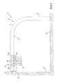
- a retractable coverage system to provide protection against the sun and rain comprising a supporting frame 2 which, in turn, comprises, in this example, two metal sections 3 parallel to one another, which extend between the ground S and a substantially vertical supporting wall, are fixed to the ground S and to the wall 4, have a substantially U-shaped cross-section with the concavity facing downwards, and each of which comprises two respective lower longitudinal edges 5 ( figure 4 ) which are folded inwards so as to be coplanar with respect to each other.
- Each section 3 is also shaped, comprises a substantially vertical lower segment 6 that protrudes upwards from the ground S and an upper and at least partially curvilinear segment which extends between the segment 6 and the wall 4, and internally defines a guide 8 ( figure 4 ).
- the coverage system 1 further comprises, in this example, a cover sheet 9, which extends between the two sections 3, has an upper edge 10 fixed to the wall 4, and is limited by two lateral edges 11, each of which is fixed to a relative string of carriages 12, which are housed inside a relative guide 8, and define, with the carriages 12 of the other guide 8, an actuating device 13 for moving the sheet 9 between a work condition (not illustrated), in which the sheet 9 is pulled out along the sections 3, and a rest position ( figure 2 ), in which the sheet 9 is gathered at the top in proximity to said wall 4.
- a cover sheet 9 which extends between the two sections 3, has an upper edge 10 fixed to the wall 4, and is limited by two lateral edges 11, each of which is fixed to a relative string of carriages 12, which are housed inside a relative guide 8, and define, with the carriages 12 of the other guide 8, an actuating device 13 for moving the sheet 9 between a work condition (not illustrated), in which the sheet 9 is pulled out along the sections 3, and a rest position ( figure 2 ), in which
- Each string of carriages 12 comprises a first carriage 12 (hereinafter designated by 12a), which is fixed to a free end of the relative edge 11, and is aligned with the carriage 12a of the other guide 8 in a horizontal direction 14 transversal to the sections 3, and a plurality of intermediate carriages 12 (hereinafter designated by 12b), which are arranged between the wall 4 and the carriage 12a, and each of which is aligned with a corresponding carriage 12b of the other guide 8 in direction 14.
- 12a first carriage 12
- 12b a plurality of intermediate carriages 12
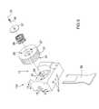
- each carriage 12a, 12b comprises a supporting body 15; a first set of four wheels 16, which cooperate two by two with the lower edges 5 of the relative guide 8, are coaxial two by two with respect to one another, and are mounted so as to rotate, with respect to the body 15, about respective longitudinal axes 17 parallel to the direction 14; and a second set of four wheels 18, which cooperate with a surface 19 of the relative guide 8 parallel and opposite to the relative edges 5, and are mounted so as to rotate about respective longitudinal axes 20 parallel to one another and to direction 14.
- the wheels 18 are mounted on respective supports (not illustrated), which are slidingly coupled to the body 15 by means of the interposition of relative damping springs (not illustrated) so as to move, with respect to the body 15, in a straight line in a direction 21 orthogonal to the edges 5 and to the surface 19, and allow the carriage 12a, 12b to couple without clearance with the relative segment 6 and with any straight portions of the relative segment 7, and to correctly follow the curvilinear portions of said relative segment 7.
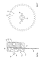
- Each carriage 12a further supports a toothed wheel 22, which has a longitudinal axis 23 parallel to the direction 14, protrudes upwards from the body 15 to couple with a toothed belt 24 fixed along the surface 19 of the relative guide 8, and is axially limited by two flat surfaces 25, 26 ( figures 5 and 7 ) substantially orthogonal to the axis 23, and the surface 25 of which faces the body 15.
- the wheel 22 has a cavity 27 obtained in the surface 26 coaxially with respect to the axis 23, is provided with two radial slits 28 arranged opposite one another obtained in the surface 25, and is slidingly fixed to a drive shaft 29, which extends through the wheel 22 coaxial with respect to the axis 23, is pivotally coupled to the body 15 so as to rotate, with respect to the body 15, about the axis 23, and is provided with two radial coupling pins 30 which protrude radially outwards from the shaft 29.
- the shaft 29 is made to rotate about the axis 23 by an electric motor 31, which is fixed to the body 15 inside the relative guide 8, is interconnected to and phased with the motor 31 of the other carriage 12a by means of an electronic control unit (not illustrated), and is powered by means of a power supply device 32 with sliding electrical contacts comprising a pair of guides 33 made of a conductive material fixed along the surface 19 and a pair of electrical contacts 34 which are also made of a conductive material borne by the carriage 12a.
- the contacts 34 are mounted on a plate 35 which is slidingly coupled to the body 15 so as to move, with respect to the body 15, in the direction 21 between an extracted work position, in which the contacts 34 protrude from the body 15 in the direction 21 so as to come into contact with the relative guides 33, and a retracted rest position, in which the contacts 34 do not engage said relative guides 33.
- the motor 31 has an output shaft (not illustrated) defined by a worm screw, which extends transversely with respect to the directions 14 and 21, and is coupled to a worm wheel (not illustrated) obtained on one end of the shaft 29.
- the wheel 22 is moved to, and normally maintained in, a locking position, in which the pins 30 engage the relative slits 28 to angularly lock the wheel 22 to the shaft 29, by a spring 36, which is housed in the cavity 27 coaxially to the axis 23, and is held inside the cavity 27 by a plate 37, which is mounted orthogonally to the axis 23 to close the cavity 27, and is axially locked to the shaft 29 by means of a lock screw 38 screwed into the shaft 29 parallel to said axis 23.
- the wheel 22 In the event of an interruption in the electric power supply or a motor 31 malfunction, the wheel 22 is moved from its locking position to a release position, in which the slits 28 disengage the pins 30 to allow the wheel 22 to become uncoupled from the shaft 29 and so that the carriage 12a can slide along the guide 8, by a releasing member 39, which is substantially fork shaped, is inserted manually between the body 15 and the wheel 22 through the two edges 5 of the guide 8 and through two holes 40 obtained in the body 15 parallel to the direction 21, and is turned (in a clockwise direction in figure 6 ) to move the wheel 22 in the direction 14 against the action of the spring 36.
- a releasing member 39 which is substantially fork shaped
- each section 3 can be produced as a single piece, and the sheet 9 can be moved between the ground S and the wall 4.
- the cover sheet 9 is eliminated and replaced with a plurality of coverage panels, equal in number to the number of carriages 12a, 12b mounted inside a guide 8, and which extend between the two sections 3, and are borne one by the two carriages 12a and each of the others by a relative pair of corresponding carriages 12b.
- Each panel is provided with a pair of fastening tabs, which are arranged on opposite sides of the panel, and one of which enables said panel to couple with the adjacent panel when the panels are moved into their work position and the other when the panels are moved into their rest position, in which the panels are arranged one on top of the other.
- the present invention is used to particular advantage in a retractable wall used, for example, to divide and/or shut-off areas of a room.
- the retractable wall comprises at least one shaped guide, which is fixed to a floor or to a ceiling of the room, and has at least one curvilinear segment; at least one panel extending in a substantially vertical containing plane; and an actuating device for moving the panel along the guide and comprising at least one motor powered carriage identical to the carriages 12a.
- the two sections 3 are substantially U-shaped with the concavity facing downwards and are fastened to the ground S in correspondence with both of the free ends.
- the coverage system 1 comprises a first substantially circular guide fastened to the ground S or to the top of a supporting post structure; a carriage 12 mounted inside the first guide; and a cover sheet, which has a lower edge that is movable along the first guide, an upper edge engaged in a second guide arranged on top of the first guide, a first transverse edge anchored to the supporting structure, and a second transverse edge fixed to the carriage 12 so as to allow the carriage 12 to move the sheet from and towards a coverage work position, in which the sheet has a substantially truncated cone shape.
- the two sections 3 are straight.
- each carriage 12 is provided with the relative motor 31, the coverage system 1 is relatively simple and quick to install and does not require external actuating motors to be mounted on the sections 3.
Landscapes
- Engineering & Computer Science (AREA)
- Architecture (AREA)
- Civil Engineering (AREA)
- Structural Engineering (AREA)
- Power-Operated Mechanisms For Wings (AREA)
- Ship Loading And Unloading (AREA)
- Soil Working Implements (AREA)
- Buildings Adapted To Withstand Abnormal External Influences (AREA)
- Automatic Assembly (AREA)
- Fittings On The Vehicle Exterior For Carrying Loads, And Devices For Holding Or Mounting Articles (AREA)
- Protection Of Plants (AREA)
Applications Claiming Priority (1)
| Application Number | Priority Date | Filing Date | Title |
|---|---|---|---|
| ITBO2009A000458A IT1395485B1 (it) | 2009-07-16 | 2009-07-16 | Sistema di copertura mobile |
Publications (2)
| Publication Number | Publication Date |
|---|---|
| EP2292867A2 true EP2292867A2 (de) | 2011-03-09 |
| EP2292867A3 EP2292867A3 (de) | 2015-01-28 |
Family
ID=42035731
Family Applications (1)
| Application Number | Title | Priority Date | Filing Date |
|---|---|---|---|
| EP10169937.9A Withdrawn EP2292867A3 (de) | 2009-07-16 | 2010-07-16 | Einziehbare Abdeckvorrichtung |
Country Status (2)
| Country | Link |
|---|---|
| EP (1) | EP2292867A3 (de) |
| IT (1) | IT1395485B1 (de) |
Cited By (1)
| Publication number | Priority date | Publication date | Assignee | Title |
|---|---|---|---|---|
| CN112701073A (zh) * | 2019-10-23 | 2021-04-23 | 上海微电子装备(集团)股份有限公司 | 一种存储装置及搬运装置 |
Family Cites Families (2)
| Publication number | Priority date | Publication date | Assignee | Title |
|---|---|---|---|---|
| DE3437457A1 (de) * | 1984-10-12 | 1986-04-17 | Gebr. Märklin & Cie GmbH, 7320 Göppingen | Vorhangschiene |
| ITPD20070069A1 (it) * | 2007-03-01 | 2008-09-02 | Progettotenda S P A | Tenda ad impacchettamento |
-
2009
- 2009-07-16 IT ITBO2009A000458A patent/IT1395485B1/it active
-
2010
- 2010-07-16 EP EP10169937.9A patent/EP2292867A3/de not_active Withdrawn
Non-Patent Citations (1)
| Title |
|---|
| None |
Cited By (2)
| Publication number | Priority date | Publication date | Assignee | Title |
|---|---|---|---|---|
| CN112701073A (zh) * | 2019-10-23 | 2021-04-23 | 上海微电子装备(集团)股份有限公司 | 一种存储装置及搬运装置 |
| CN112701073B (zh) * | 2019-10-23 | 2024-06-11 | 上海微电子装备(集团)股份有限公司 | 一种存储装置及搬运装置 |
Also Published As
| Publication number | Publication date |
|---|---|
| ITBO20090458A1 (it) | 2011-01-17 |
| IT1395485B1 (it) | 2012-09-28 |
| EP2292867A3 (de) | 2015-01-28 |
Similar Documents
| Publication | Publication Date | Title |
|---|---|---|
| US9722309B2 (en) | Mobile radio antenna comprising a multi beam forming device | |
| EP2322058B2 (de) | Einstellungsvorrichtung für eine Stütze und Verfahren zum Einstellen einer Lendenwirbelstütze | |
| EP3625082B1 (de) | Fahrzeugeinrichtungssystem | |
| US4619478A (en) | Powered adjustable arm rest | |
| US20130298706A1 (en) | Modular door drive | |
| US20100008606A1 (en) | Sliding support assembly | |
| WO2014186345A1 (en) | Mobile solar power rack | |
| KR100888583B1 (ko) | 차량용 프론트 시트의 높낮이 조절 장치 | |
| KR102277069B1 (ko) | 자동차 시트용 롱 슬라이드 레일 시스템 | |
| EP3112208B1 (de) | Elektrischer sitz mit vollständigem begehbarem system | |
| CN109538723B (zh) | 天线、用于电下倾角调节的传动装置及传动组件 | |
| EP2292867A2 (de) | Einziehbare Abdeckvorrichtung | |
| WO2019197290A1 (de) | Luftausströmer, modul und luftausströmeranordnung | |
| EP3983259B1 (de) | System zum positionieren eines bauteils auf dem boden der fahrgastzelle eines fahrzeuges | |
| JP7654816B2 (ja) | スライドロック装置及びスライド装置の組み立て方法 | |
| CN105270340A (zh) | 擦拭器装置和用于擦拭器装置的擦拭器刮片 | |
| US12109920B2 (en) | Adjusting device for a vehicle seat and vehicle seat | |
| CN109435797B (zh) | 一种多连杆折叠机构以及由此构成的汽车座椅 | |
| DE102008010372B3 (de) | Fahrzeugsitz mit einem Bediensystem | |
| EP3786383B1 (de) | Wandarretierungsvorrichtung, anordnung mit der wandarretierungsvorrichtung und gebäude mit der anordnung | |
| CN109469420A (zh) | 非模块型双调节器组件 | |
| EP0325094A1 (de) | Linearantriebseinheit, insbesondere geeignet zur Öffnung von Fenstern | |
| CN216731602U (zh) | 一种连续稳定的汽车前保险杠装配设备 | |
| KR102853598B1 (ko) | 차량용 시트의 파워 롱 슬라이드 장치 및 이의 설치 방법 | |
| CN216914044U (zh) | 一种能限定珍珠棉位置的卧式切料装置 |
Legal Events
| Date | Code | Title | Description |
|---|---|---|---|
| PUAI | Public reference made under article 153(3) epc to a published international application that has entered the european phase |
Free format text: ORIGINAL CODE: 0009012 |
|
| AK | Designated contracting states |
Kind code of ref document: A2 Designated state(s): AL AT BE BG CH CY CZ DE DK EE ES FI FR GB GR HR HU IE IS IT LI LT LU LV MC MK MT NL NO PL PT RO SE SI SK SM TR |
|
| AX | Request for extension of the european patent |
Extension state: BA ME RS |
|
| PUAL | Search report despatched |
Free format text: ORIGINAL CODE: 0009013 |
|
| AK | Designated contracting states |
Kind code of ref document: A3 Designated state(s): AL AT BE BG CH CY CZ DE DK EE ES FI FR GB GR HR HU IE IS IT LI LT LU LV MC MK MT NL NO PL PT RO SE SI SK SM TR |
|
| AX | Request for extension of the european patent |
Extension state: BA ME RS |
|
| RIC1 | Information provided on ipc code assigned before grant |
Ipc: E04F 10/02 20060101ALI20141222BHEP Ipc: E04F 10/06 20060101AFI20141222BHEP |
|
| STAA | Information on the status of an ep patent application or granted ep patent |
Free format text: STATUS: THE APPLICATION IS DEEMED TO BE WITHDRAWN |
|
| 18D | Application deemed to be withdrawn |
Effective date: 20150729 |