EP2292166B1 - Frakturfixationssystem - Google Patents
Frakturfixationssystem Download PDFInfo
- Publication number
- EP2292166B1 EP2292166B1 EP10182519A EP10182519A EP2292166B1 EP 2292166 B1 EP2292166 B1 EP 2292166B1 EP 10182519 A EP10182519 A EP 10182519A EP 10182519 A EP10182519 A EP 10182519A EP 2292166 B1 EP2292166 B1 EP 2292166B1
- Authority
- EP
- European Patent Office
- Prior art keywords
- pin
- shaft
- fixation
- handle
- bone
- Prior art date
- Legal status (The legal status is an assumption and is not a legal conclusion. Google has not performed a legal analysis and makes no representation as to the accuracy of the status listed.)
- Expired - Lifetime
Links
- 210000000988 bone and bone Anatomy 0.000 claims abstract description 79
- 230000037361 pathway Effects 0.000 claims abstract description 37
- 238000003780 insertion Methods 0.000 claims abstract description 15
- 230000037431 insertion Effects 0.000 claims abstract description 15
- 230000000087 stabilizing effect Effects 0.000 claims abstract description 4
- 206010017076 Fracture Diseases 0.000 description 73
- 208000010392 Bone Fractures Diseases 0.000 description 64
- 210000000236 metacarpal bone Anatomy 0.000 description 27
- 210000001872 metatarsal bone Anatomy 0.000 description 11
- 239000000463 material Substances 0.000 description 7
- 210000003811 finger Anatomy 0.000 description 6
- 238000000034 method Methods 0.000 description 6
- 206010019114 Hand fracture Diseases 0.000 description 5
- -1 e. g. Polymers 0.000 description 5
- 238000011282 treatment Methods 0.000 description 5
- 238000005452 bending Methods 0.000 description 4
- 230000035876 healing Effects 0.000 description 4
- 238000007373 indentation Methods 0.000 description 3
- 230000006641 stabilisation Effects 0.000 description 3
- 238000011105 stabilization Methods 0.000 description 3
- 229910001220 stainless steel Inorganic materials 0.000 description 3
- 239000010935 stainless steel Substances 0.000 description 3
- 210000000623 ulna Anatomy 0.000 description 3
- 239000004677 Nylon Substances 0.000 description 2
- 239000004698 Polyethylene Substances 0.000 description 2
- 229920000122 acrylonitrile butadiene styrene Polymers 0.000 description 2
- 239000004676 acrylonitrile butadiene styrene Substances 0.000 description 2
- 238000004891 communication Methods 0.000 description 2
- 210000004247 hand Anatomy 0.000 description 2
- 229910052751 metal Inorganic materials 0.000 description 2
- 239000002184 metal Substances 0.000 description 2
- 229920001778 nylon Polymers 0.000 description 2
- 239000004033 plastic Substances 0.000 description 2
- 229920003023 plastic Polymers 0.000 description 2
- 229920000515 polycarbonate Polymers 0.000 description 2
- 239000004417 polycarbonate Substances 0.000 description 2
- 229920000573 polyethylene Polymers 0.000 description 2
- 230000009467 reduction Effects 0.000 description 2
- 238000010079 rubber tapping Methods 0.000 description 2
- 238000007920 subcutaneous administration Methods 0.000 description 2
- 230000000153 supplemental effect Effects 0.000 description 2
- 208000008924 Femoral Fractures Diseases 0.000 description 1
- 208000004367 Tibial Fractures Diseases 0.000 description 1
- RTAQQCXQSZGOHL-UHFFFAOYSA-N Titanium Chemical compound [Ti] RTAQQCXQSZGOHL-UHFFFAOYSA-N 0.000 description 1
- 208000027418 Wounds and injury Diseases 0.000 description 1
- 210000000784 arm bone Anatomy 0.000 description 1
- 239000000560 biocompatible material Substances 0.000 description 1
- 238000005266 casting Methods 0.000 description 1
- 230000000295 complement effect Effects 0.000 description 1
- 238000013461 design Methods 0.000 description 1
- 230000003090 exacerbative effect Effects 0.000 description 1
- 210000002683 foot Anatomy 0.000 description 1
- 230000003100 immobilizing effect Effects 0.000 description 1
- 208000014674 injury Diseases 0.000 description 1
- 230000007246 mechanism Effects 0.000 description 1
- 238000012986 modification Methods 0.000 description 1
- 230000004048 modification Effects 0.000 description 1
- 229910052755 nonmetal Inorganic materials 0.000 description 1
- 150000002843 nonmetals Chemical class 0.000 description 1
- 239000007787 solid Substances 0.000 description 1
- 230000003319 supportive effect Effects 0.000 description 1
- 238000001356 surgical procedure Methods 0.000 description 1
- 210000003813 thumb Anatomy 0.000 description 1
- 210000001519 tissue Anatomy 0.000 description 1
- 239000010936 titanium Substances 0.000 description 1
- 229910052719 titanium Inorganic materials 0.000 description 1
- 210000003371 toe Anatomy 0.000 description 1
- 230000008733 trauma Effects 0.000 description 1
- 230000000472 traumatic effect Effects 0.000 description 1
Images


Classifications
-
- A—HUMAN NECESSITIES
- A61—MEDICAL OR VETERINARY SCIENCE; HYGIENE
- A61B—DIAGNOSIS; SURGERY; IDENTIFICATION
- A61B17/00—Surgical instruments, devices or methods
- A61B17/56—Surgical instruments or methods for treatment of bones or joints; Devices specially adapted therefor
- A61B17/58—Surgical instruments or methods for treatment of bones or joints; Devices specially adapted therefor for osteosynthesis, e.g. bone plates, screws or setting implements
- A61B17/68—Internal fixation devices, including fasteners and spinal fixators, even if a part thereof projects from the skin
- A61B17/72—Intramedullary devices, e.g. pins or nails
- A61B17/7291—Intramedullary devices, e.g. pins or nails for small bones, e.g. in the foot, ankle, hand or wrist
-
- A—HUMAN NECESSITIES
- A61—MEDICAL OR VETERINARY SCIENCE; HYGIENE
- A61B—DIAGNOSIS; SURGERY; IDENTIFICATION
- A61B17/00—Surgical instruments, devices or methods
- A61B17/16—Instruments for performing osteoclasis; Drills or chisels for bones; Trepans
- A61B17/1662—Instruments for performing osteoclasis; Drills or chisels for bones; Trepans for particular parts of the body
- A61B17/1682—Instruments for performing osteoclasis; Drills or chisels for bones; Trepans for particular parts of the body for the foot or ankle
-
- A—HUMAN NECESSITIES
- A61—MEDICAL OR VETERINARY SCIENCE; HYGIENE
- A61B—DIAGNOSIS; SURGERY; IDENTIFICATION
- A61B17/00—Surgical instruments, devices or methods
- A61B17/16—Instruments for performing osteoclasis; Drills or chisels for bones; Trepans
- A61B17/1662—Instruments for performing osteoclasis; Drills or chisels for bones; Trepans for particular parts of the body
- A61B17/1686—Instruments for performing osteoclasis; Drills or chisels for bones; Trepans for particular parts of the body for the hand or wrist
-
- A—HUMAN NECESSITIES
- A61—MEDICAL OR VETERINARY SCIENCE; HYGIENE
- A61B—DIAGNOSIS; SURGERY; IDENTIFICATION
- A61B17/00—Surgical instruments, devices or methods
- A61B17/56—Surgical instruments or methods for treatment of bones or joints; Devices specially adapted therefor
- A61B17/58—Surgical instruments or methods for treatment of bones or joints; Devices specially adapted therefor for osteosynthesis, e.g. bone plates, screws or setting implements
- A61B17/68—Internal fixation devices, including fasteners and spinal fixators, even if a part thereof projects from the skin
- A61B17/72—Intramedullary devices, e.g. pins or nails
- A61B17/7208—Flexible pins, e.g. ENDER pins
-
- A—HUMAN NECESSITIES
- A61—MEDICAL OR VETERINARY SCIENCE; HYGIENE
- A61B—DIAGNOSIS; SURGERY; IDENTIFICATION
- A61B17/00—Surgical instruments, devices or methods
- A61B17/56—Surgical instruments or methods for treatment of bones or joints; Devices specially adapted therefor
- A61B17/58—Surgical instruments or methods for treatment of bones or joints; Devices specially adapted therefor for osteosynthesis, e.g. bone plates, screws or setting implements
- A61B17/88—Osteosynthesis instruments; Methods or means for implanting or extracting internal or external fixation devices
- A61B17/92—Impactors or extractors, e.g. for removing intramedullary devices
- A61B17/921—Impactors or extractors, e.g. for removing intramedullary devices for intramedullary devices
Definitions
- This invention relates broadly to a system for bone fracture fixation. More particularly, this invention relates to a system for fixation of fractures of relatively small bones.
- Metacarpal fractures are very common. Immobilization of the metacarpal bone on either side of the fracture is imperative for proper healing. However, the location of the fracture presents several difficulties to ideal immobilization.
- An alternative less invasive technique has been used in which a small incision is made in the skin proximal the metacarpal bone, a boring tool is inserted through the incision and is used to drill a small hole into the metacarpal bone, the boring tool is removed, and then the physician feeds the pin through the incision and into the small unseen bore in the bone.
- feeding the pin through the skin is a blind operation with no manner provided for indicating to the physician the relative location of the pin and the small hole bored in the bone.
- the technique is objectionable to both physician and patient as blind feeding can result in exacerbating damage to the surrounding tissue.
- the implanted pin fails to provide torsional fixation for fractures which need to be rotationally immobilized.
- US-2631584 discloses a fracture securing instrument.
- the instrument is adapted to secure bone fractures by the insertion of a nail therein.
- the instrument comprises a tubular nail having an offset opening in the side thereof with an angular face extending transversely to the axis of the nail.
- a pin is slidably mounted and entirely contained within the nail.
- the pin has a shank arranged to engage the angular face and to be deflected laterally through the opening.
- a mechanism is provided for holding the nail in place and for applying continuous pressure to the pin to move the pin relative to the nail and against the angular face.
- US-5603715 discloses a medullary pin for intramedullary use in the healing of damage to bones.
- the pin is insertable into the medullary canal of the bone and can be secured to the bone with fixation means at both ends. Wires are arranged to pass through an interior space of the pin and to exit through a lateral opening in the pin.
- a fracture fixation system is provided.
- the fracture fixation system generally will be described with reference to the metacarpal bones, although it also applies to metatarsal bones, phalangeal bones, similar bones.
- the system facilitates the insertion of one or more fixation pins into the medullary canal of a fractured metacarpal bone for stable bone fixation.
- a fracture fixation system for stabilizing a fracture of a human bone, said system comprising: a fixation pin having a proximal end and a distal end, said fixation pin being sized to fit within the medullary canal of the bone and having a stiffness sufficient to immobilize the fracture and a flexibility sufficient to permit the fixation pin to bend to facilitate insertion into the medullary canal; and an elongate shaft having a proximal end, a distal end with means for boring a hole in the bone in a first direction axial with said shaft, an axial pathway and a pin guide comprising a distal laterally exiting bore in said shaft adjacent said distal end of said shaft and communicating with said axial pathway; wherein said shaft is arranged to guide said fixation pin axially through said axial pathway and the laterally exiting bore to guide said fixation pin beyond said distal end of said shaft into the medullary canal of the bone at an oblique angle relative to said first direction; and
- the instrument includes a shaft handle having at its distal end a boring shaft coupled thereto.
- the boring shaft has an internal pathway and a distal exit.
- the shaft handle includes a throughbore in communication with the internal pathway of the shaft and through which the fixation pin can be received.
- the handle permits manual subcutaneous insertion and rotation of the shaft to provide the tip of the boring shaft into the metacarpal bone.
- the distal exit is lateral.
- An awl member may be optionally provided in the throughbore and internal pathway and extended to the distal exit of the shaft for shaft insertion into the metacarpal bone, and then removed for extending the fixation pin through the internal pathway and distal exit of the shaft.
- the pathway of the boring shaft is provided with a proximal lateral entrance, and exits either laterally or axially at the distal end of the shaft.
- fixation pin may alternatively be adapted to be self-guiding to follow the medullary canal.
- the proximal and central portions of the pin are relatively straight and sufficiently stiff (providing fixation, yet permitting forced insertion into bone).
- a reduced diameter portion Adjacent the distal end, a reduced diameter portion may be provided which permits the distal end to easily bend relative to the central portion and follow the medullary canal.
- a coil is provided about the reduced diameter portion to provide the pin with an apparently constant diameter.
- the fixation pin may be particularly adapted for use in relatively small medullary canals such as that found in the phalanges, i. e., the fixation pin may have a relatively small distal diameter.
- the fixation pin includes a proximal end having a uniform diameter, and a distal end having a relatively smaller diameter, and a tapered or stepped portion therebetween.
- the fixation system includes a plurality of fixation pins and an instrument for sequentially implanting at least two of the fixation pins into the medullary canal of a fractured bone.
- the instrument is substantially as described above, with each of the pins separately providable into the pin handle.
- the pins may have the same diameter or may be provided as a set to include pins of various diameters.
- Each individual pin is smaller than the medullary canal of the bone, yet when implanted in combination with one or more others of the pins provides a fixation system which approximates the inner diameter of the medullary canal in order to provide the required fixation.
- Each individual pin is implanted as described above, and at least two pins are implanted to stabilize the fracture.
- a collet is preferably provided over the proximal ends of the pins to couple the pins together and thereby prevent relative rotation of the pins.
- the collet is preferably adapted to be coupled to the bone to immobilize the proximal ends of the pins relative to the bone. As such, the fixation system provides torsional stabilization to the fracture.
- a fracture fixation system for stabilizing a fracture of a human bone, comprises a fixation pin having a proximal end and a distal end; and an elongate shaft having a proximal end, a distal end with means for boring a hole in the bone, and a pin guide adjacent said distal end of said shaft for guiding said fixation pin into a medullary canal of the bone, said fixation pin and said shaft both adapted such that said distal end of said fixation pin is movable beyond said distal end of said shaft.
- a first handle may be coupled to said proximal end of said fixation pin which facilitates movement of said fixation pin relative to said shaft and through said pin guide, said first handle preferably including a finger engageable structure which facilitates movement of said fixation pin into the medullary canal.
- a second handle may be coupled to said proximal end of said shaft to facilitate movement of said shaft into the bone, said second handle preferably provided with a longitudinal opening into which said first handle is received and distally slidable therein. Said first handle may be either removable from said longitudinal opening or releasably engageable within said longitudinal opening.
- Said means for boring may include a plurality of cutting edges which meet at a point.
- At least one of said first handle and said second handle may be provided with means for gripping with a hand of a person.
- a guide tool may have a shaft provided with a slot, said slot having a lateral opening sized to fit over said fixation pin.
- Said fixation pin may comprise an elongate rod having a proximal portion, a central portion, and a curved distal portion.
- Said proximal portion is straight and said central portion is straight and/or said central portion is angled at an angle relative to said proximal portion where said angle is preferably approximately 5° to 8° and said curved distal portion preferably has a radius of curvature of approximately 12.7 mm (0.5 inch).
- Said fixation pin may be provided with a reduced diameter portion adjacent said distal end of said fixation pin, and a coil may be preferably provided about said reduced diameter portion.
- Said pin guide may be adapted to deflect said distal end of said fixation pin at an angle relative to a longitudinal axis of said shaft when said fixation pin is moved distally relative to said shaft.
- Said fixation pin may have a distal portion terminating in said distal end, said distal portion having non-linear shape, and said pin guide may define a non-linear shape substantially similar to said non-linear shape of said distal portion of said fixation pin, such that when said boring tip of said shaft is entered into the bone and said fixation pin may be moved distally relative to said shaft, said pin guide guides said fixation pin into said medullary canal of the bone at an angle relative to a longitudinal axis of said shaft.
- Said non-linear shape of said distal portion of said fixation pin may include a proximal straight first portion and a curved distal second portion.
- Said fixation pin may be sized to fit into the medullary canal of one of a human metacarpal bone, human metatarsal bone, human phalangeal bone, pediatric ulna bone, and paediatric radial bone.
- Said fixation pin may be sized to snugly fit within the medullary canal of the bone and has a stiffness sufficient to immobilize the fracture and a flexibility sufficient to permit the fixation pin to bend to facilitate insertion into the medullary canal.
- At least one additional fixation pin may be provided, said fixation pins each being sized to fit together within the medullary canal of the bone and having a combined stiffness sufficient to immobilize the fracture and an individual flexibility sufficient to permit each of said plurality of fixation pins to bend to facilitate insertion into the medullary canal.
- a means for securing said proximal ends of said fixation pins together may be provided.
- Said means for securing additionally may secure said fixation pins to the bone.
- Said means for securing may include a collet and a fastener, said collet surrounding said proximal ends of said fixation pins, and said fastener extending through said collet and into the bone, said collet preferably provided with self-tapping threads.
- Said fixation pins may be sized to fit together within the medullary canal of one of a human metacarpal bone, human metatarsal bone, human phalangeal bone, pediatric ulna bone, and pediatric radial bone.
- Each of said plurality of fixation pins may be provided with a distal diameter between approximately 0.889 mm -1.524 mm (0.035 inch - 0.060 inch).
- FIG. 1 through 4 a metacarpal fracture fixation system 10 for the insertion of a fixation pin into the medullary canal of a fractured metacarpal bone is shown.
- the system 10 includes a fixation pin 12 and an instrument 14 for implanting the fixation pin.
- the instrument 14 includes a main handle 16 provided with a stationary drill 40, and a pin handle 18 movable relative to the main handle for implanting the fixation pin 12.
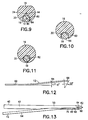
- the main handle 16 includes a proximal end 20, a preferably frustoconical distal end 22, a longitudinal drill slot 24 (seen best in Figs. 1 and 9 ) preferably in alignment with a longitudinal axis A H of the main handle 16, two radial bores 26,28 which extend into the drill slot 24, and a pin handle slot 30 and pin handle bore 32 (seen best in Figs. 11 and 15 ), both for receiving the pin handle 18, as described below.
- the main handle 16 is preferably chamfered about the pin handle slot 30, and also preferably includes a plurality of indentations 34 to facilitate engagement of the main handle 16 by the fingers of one hand (or both hands) of the physician.
- the main handle is preferably molded from plastic, e. g., ABS, nylon, polycarbonate, or polyethylene, but may be machined from a Delrin TM rod or a similar material.
- the drill 40 is provided in the longitudinal drill slot 24.
- the drill 40 includes a shaft 42 having a proximal end 44 provided with two lateral bores 46, 48 ( Fig. 2 ), and a distal end 50 described in detail below.
- the drill 40 is fixed in the main handle 16 with two pins 54, 56 secured, preferably by interference fit, through the lateral bores 26, 28 in the main handle 16 and into the lateral bores 46,48 in the shaft 42 of the drill 40.
- the drill 40 is preferably made from a stainless steel bar having a 3.175 mm (0.125 inch) diameter and a length of approximately 14.48 cm (5.7 inches). Approximately 4.32 cm (1.7 inches) of the shaft is provided in the handle and approximately 10.16 cm (4 inches) of the shaft extend distally from the main handle 16.
- the distal end 50 of the shaft 42 of the drill 40 includes a boring tip 60 which preferably comprises three cutting edges 62, 64, 66 displaced 120° from each other about the boring tip and tapered to a point 68.
- the taper is preferably at approximately 13° relative to the longitudinal axis As.
- the distal end 52 is provided with a lateral guiding groove 70 which guides the fixation pin 12.
- the guiding groove 70 includes a proximal sloped portion 72 and a distal curved deflecting portion 74.
- the sloped portion is preferably sloped such that a line L P perpendicular to a surface 76 of the sloped portion 70 is angled approximately 5° to 8° relative to a line L S perpendicular to the axis As of the shaft 42.
- the curved portion 74 preferably has a radius of approximately 12.7 mm (0.50 inches).
- the guiding groove 70 preferably extends into the shaft 42 a groove depth D G of approximately 2.794 mm (0.110 inches) at the intersection of the sloped portion 72 and the curved portion 74, and preferably has a width W G of approximately 1.6 mm (0.063 inches).
- the groove depth D G is preferably greater than the diameter of the pin 12 such that the combined diameters of the pin 12 and the shaft 42 at the guiding groove 70 does not exceed the outer diameter of the shaft ( Fig. 13 ).
- the width W G is preferably 0.051 - 0.076 mm (0.002- 0.003 inch) greater than the diameter of the pin so that the pin is accurately guided without binding.
- the pin handle 18 includes a distal portion 80 which is sized and shaped to slidably move within the pin handle slot 30 of the main handle 16, and a proximal portion 82 which is sized and shaped to slidably move within the pin handle bore 32 of the main handle 16.
- a lower area 84 of the distal portion 80 includes a plurality of indentations 86 which facilitates movement of the pin handle 18 relative to the main handle 16 by fingers of the physician.
- a distal end 88 of the pin handle 18 is chamfered and provided with a bore 90 into which the fixation pin 12 is secured, preferably by an interference fit.
- the pin handle 18, like the main handle 16, is also preferably molded from plastic, e. g., ABS, nylon, polycarbonate, or polyethylene, but may be machined from a Delrin TM rod or a similar material.
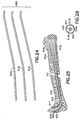
- the fixation pin 12 preferably includes a substantially straight proximal portion 92, the end of which is secured in the distal end 88 of the pin handle 18, a substantially straight central portion 94, which may optionally be angled relative to the proximal portion 92, and a curved, distal portion 96 having a preferably blunt tip 98. If the proximal portion 92 and central portion 94 are angled relative to each other, it is preferable that the angle be approximately 5° -8°.
- the distal tip 96 is preferably curved about an approximately 12.7 mm (0.50 inch) radius for approximately 33° degrees.
- the fixation pin 12 is preferably made from a solid metal wire material, e. g., stainless steel.
- the fixation pin must have a stiffness sufficient to immobilize the bone fracture, yet be resiliently flexible enough to permit the pin 12 to be sufficiently bent for insertion into the medullary canal of the bone, as described below. Therefore, the system 10 may include a plurality of fixation pins 12 having various diameters.
- One preferred fixation pin 12 preferably has a length of approximately 15.24 cm (6.0 inches), with approximately 17.78 mm (0.70 inches) secured in the distal bore 90 of the pin handle 18, and a diameter of approximately 1.524 mm (0.060 inches).
- the fixation pin 12 is positioned in the pin handle 18, and the pin handle 18 in the main handle 16 such that the curved distal portion 96 of the fixation pin 12 rests within the guiding groove 70 of the shaft 42 of the drill 40, and the distal portion 96 does not extend beyond the circumferential profile of the shaft.
- movement of the pin handle 18 within the pin handle slot 30 and pin handle bore 32 of the main handle 16 distally relative to the main handle causes the distal portion 96 of the fixation pin 12 to move relative to the shaft 42 of the drill 40, through the guiding groove 70, and to extend beyond the boring tip 60, preferably at an angle relative to the axis of the shaft As.
- the pin handle may be moved to extend the distal end of the pin preferably at least 6.35 mm (one quarter inch), and more preferably 2.54 to 7.62 cm (one to three inches), beyond the distal end of the shaft while remaining coupled to the main handle. Moreover, it will be appreciated that no impediment is present which inhibits the pin handle 18 from being moved distally relative to the main handle 16, or the main handle moved proximally relative to the pin handle. As such, as shown in Fig. 15 , the pin handle may be separated from the main handle.
- the main handle 16 of the instrument 14 is manipulated by hand to subcutaneously introduce the boring tip 60 of the drill 40 into the base of a fractured metacarpal bone.
- the drill is oriented such that the guiding groove 70 is oriented to guide the fixation pin 12 through the natural hollow of the medullary canal of the metacarpal bone.
- the pin handle 18 is then manually moved relative to the main handle 16 to force the curved distal portion 96 of the fixation pin 12 into the bone.
- the main handle 16 is then moved proximally relative to the pin handle 18 to remove the drill 40 from the bone and disengage the main handle from the pin handle.
- the 5° -8° angle of the central portion of the pin relative to the proximal portion of the pin is substantially similar to the 5° -8° angle of the proximal portion of the groove, and the 12.7 mm (0.50 inch) radius of curvature of the distal portion of the pin is substantially the same as the 12.7 mm (0.50 inch) radius of curvature of the distal portion of the groove), facilitates directing the fixation pin into the medullary canal.
- the blunt tip 98 of the fixation pin 12 prevents the pin from piercing the distal end of the metacarpal bone.
- the pin handle 18 may then be manipulated to bend the fixation pin 12 adjacent the cutaneous entrance hole, the pin is cut, and the cut end is either subcutaneously seated or covered with a bandage outside the skin. After fracture healing, the fixation pin is extracted, e. g., with pliers, from the bone and then discarded. The cutaneous entrance hole is then permitted to heal.
- the described fracture fixation system provides substantial fixation to a metacarpal fracture, yet does not require an unduly invasive procedure or a large number of steps.
- the procedure reduces the number of physician "hands", relative to invasive surgery, required to sufficiently immobilize a fracture for proper healing.
- the instrument 214 includes a shaft 240 having a distal guiding groove 270 and sharp boring end 260.
- the shaft 240 includes a shaft handle 216 for manipulating the shaft.
- the shaft handle 216 includes a slot 230 into which a pin handle 218 is slidably received.
- the slot 230 preferably slopes downward toward the shaft.
- the shaft handle 216 is further provided with grips 217 for stably gripping the shaft handle 216 in a hand of the physician.
- the pin handle 218 includes a ridge 219 which may be used to leverage relative distal movement of the pin handle through the slot 230 of the shaft handle 216.
- the pin handle 218 and the shaft handle 216 are preferably positively engagable relative to each other, e. g., with a snap fit, and may be disengaged by sufficient force on the ridge 219 of the pin handle to move the pin handle relative to the shaft handle. Release may also provide tactile indication that the handles have disengaged and a tip 298 of the pin 212 has moved slightly ahead of the boring tip 260 of the shaft 240.
- the slope of the slot 230 permits a fixation pin 212 provided axial within the pin handle to be directed toward and through the guiding groove 270 when the pin handle is located in the slot 230 and moved within the slot.
- the pin 212 is preferably angled relative to a longitudinal axis Ap of the shaft handle 216 such that the pin 212 is directed toward the shaft 240.
- the fixation pin 212 includes a proximal portion 292 and a central portion 294 which are coaxially aligned, and a distal portion 296 provided with the blunt, preferably curved tip 298.
- the pin handle 218 is moved distally relative to the shaft handle to move the pin 212 through the guiding groove 270 and into the medullary canal of the fractured bone.
- the shaft handle 216 is then removed from the pin handle 218, and the pin handle is manipulated to further extend the fixation pin through the medullary canal of the bone and fixate the bone.
- fixation pins including fixation pins having distal portions of various sizes (e. g., substantially 1.524 mm (0.060 inch), substantially 1.295 mm (0.051 inch), substantially 1.143 mm (0.045 inch), substantially 0.965 mm (0.038 inch), and substantially 0.889 mm (0.035 inch)) is provided for use by the physician.
- a supplemental re-guiding tool 300 may be provided in the system of the invention.
- the reguiding tool 300 includes a handle 302, a slotted shaft 304 extending from one end 306 of the handle and having an inclined leading edge 308, and a tubular bending portion 310 extending from the other end 312 of the handle.
- the handle 302 is preferably further provided with a depression 314 into which the thumb of the physician may seat and which thereby facilitates gripping the handle.
- the slotted shaft 304 of the re-guiding tool 300 may be extended over the fixation pin which the physician wants to replace, through the entry hole in the hand, and into the hole in the bone.
- the inclined leading edge 308 facilitates insertion of the shaft through the wound of the hand with minimal trauma to the area. It will be appreciated that the slotted shaft design provides a less traumatic manner of maintaining a pathway from the entry hole in the skin to the bone than reinserting the distal end of the boring shaft (drill).
- the fixation pin may then be removed, while the slotted shaft 304 acts as a guide for the replacement pin.
- the pin is cut and the reguiding tool 300 may be reversed and the bending portion 310 may be extended over the cut pin and used to leverage the bending of the pin for subsequent subcutaneous seating.
- the guide tool 300 is most appropriately used with the first and second embodiments of the invention (which are provided with lateral pin guides), it will be appreciated that the guide tool may also be used with any of the following embodiments.
- the instrument 414 includes a shaft handle 416 having an axial throughbore 424 and a boring shaft 440 coupled in the distal end thereof.
- the shaft 440 is cannulated; i. e., the shaft 440 is provided with an internal pathway 470, and preferably includes a distal tip 460 with an axial pathway exit 471 and a preferably sharp annular cutting edge 473.
- the axial throughbore 424 and internal pathway 470 are in communication with each other and preferably axially aligned.
- a rod-like awl 419, provided with a proximal handle 421, is extendable through and removable from the pathway 470.
- the awl 419 preferably has a length such that when the handle 421 of the awl is seated flushly against the shaft handle 416, the tip 423 of the awl extends through the pathway exit 471 and operates as a boring tip.
- the inner awl and shaft may be locked together for insertion into the bone.
- the awl is then unlocked and removed from the internal pathway 470 to permit a fixation pin 412 to be fed through the pathway 470 and out the pathway exit 471 ( Fig. 19 ).
- the awl handle 421 and shaft handle 416 is used to insert the tip 423 of the awl 419 and the tip 460 of the shaft 440 into the metacarpal bone.
- the awl handle 421 is then removed from the pathway 470, and the fixation pin 412 is maneuvered through the pathway and into the medullary canal.
- the main handle 416 is proximally removed from over the pin 412. The pin may then be further manipulated, and is finally cut at the desired length.
- the instrument 514 includes a main handle 516 having a throughbore 524 and a boring shaft 540 coupled in the distal end thereof.
- the boring shaft 540 is cannulated and, at its distal end 550 includes a sharp boring distal tip 560 and a lateral pathway exit 571.
- a rod (not shown, but similar to the awl described with respect to the second embodiment) may be provided within the pathway 570 such that it closes the pathway exit 571 and thereby facilitates insertion of the shaft 540 into the bone.
- the rod if provided, is then removed.
- a fixation pin 512 is then extended through the pathway 570 and into the medullary canal of the metacarpal bones.
- the instrument 614 includes a cannulated boring shaft 640 preferably provided with a proximal shaft handle 616, and a fixation pin 612 optionally having a pin handle 618 coupled to its proximal end.
- the cannulated shaft 640 includes a proximal lateral pin entry 669 into an axial pathway 670 of the shaft 640, and a distal lateral pathway exit 671 oriented to guide the pin into the medullary canal.
- the pathway exit 671 may be axially aligned with the pathway 670 for axial guidance of the pin.
- the pin 612 manipulated through the shaft 640 and into the canal of the fractured bone to fixate the bone.
- the shaft 640 and shaft handle 616 are then proximally withdrawn over the pin 612, and the pin is manipulated such that it is sufficiently inserted, bent, and finally cut to the desired length.
- the shaft 640 is moved proximally over the pin 612 toward the pin handle 618 such that the pin may be further manipulated and cut to the desired length.
- the fixation pin used in each of the above instruments may be alternatively configured.
- the fixation pin 712 may be provided with a narrowed portion 722 (i. e., a reduced diameter) adjacent the tip 720 about which a coil 724 is preferably positioned. This configuration is provided to permit the distal end 718 of the fixation pin to more easily bend and permit the fixation pin to preferably be self-guiding to follow the medullary canal.
- the pin 712 may be made from titanium, or another structurally supportive biocompatible material.
- the pin handle 818 of the fixation system 810 may be provided with a set of fixation pins, substantially as described above with respect to the first embodiment but having a variety of distal dimensions.
- a pin 812 may be desirable to insert a pin 812 into a phalangeal medullary canal having a relatively smaller distal diameter than would be desirable for a metacarpal bone.
- the dimensions of the proximal portion 892 of the pins may be provided with a preferably uniform dimension.
- some fixation pins 812 may have a distally tapered portion 813 (or alternatively a step 813a, shown in dotted line), along the proximal portion 892 of the pin to taper to their respective distal dimension.
- a fixation system may be provided with a plurality, or set 900, of fixation pins 912a, 912b, 912c, having the same or different relative sizes.
- Each individual pin is smaller than the medullary canal of the bone, yet when implanted in combination with one or more others of the set provides a fixation system which approximates the inner diameter of the medullary canal in order to provide the required fixation.
- the pins are individually inserted into the medullary canal of the fractured bone substantially as described above; i.
- a first pin 912a is provided in the pin handle and inserted into the medullary canal 913 of a bone 915 to extend across a fracture 911 in the bone, as described above.
- a second pin 912b is inserted alongside the first pin 912a, and optionally additional pins, e. g., 912c, are likewise inserted.
- the distal ends of the pins may diverge to rest or imbed in different portions of the bone, as shown or, alternatively, may remain substantially aligned. Referring to Figs.
- a cylindrical collet 917 is then positioned over the exposed proximal ends of the pins to constrain the pins together such that the pins are substantially prevented from relative axial rotation.
- the collet 917 preferably includes a central opening 919 adapted to stably secure the pins.
- the central opening 919 may be circular with a diameter adapted to hold the three pins together.
- the collet 917 also preferably includes a means for securing the collet, and therefore the proximal ends of the fixation pins, to the fractured bone, e. g., external and preferably self-tapping threads 921.
- An external flange 923 adapted to assist in seating the collet at the desired depth in the bone is also preferably provided.
- the fixation system provides torsional stabilization to the fracture.
- Figs. 27 and 28 in another torsionally stabilized fracture fixation system, two pins 1012a, 1012b are inserted into the bone 1015 to bridge the fracture 1011 as described above.
- a collet 1017 having three openings 1019a, 1019b, 1019c (or a collet 1117 having a single clover-shaped opening 1119, as shown in Fig. 29 ) is provided over the proximal ends of the pins with the pins extending through two of the openings 1019a, 1019b.
- a nail 1121 is provided and secured into the bone to immobilize the collet 1017 relative to the bone.
- the teaching here is for the use of the system of the invention with the like bones.
- suitable materials have been disclosed with respect to the various components of the system of the invention, it will be appreciated that other suitable materials may be used as well.
- a metal fixation pin has been described, less preferred alternative materials for the fixation pin are nonmetals, in particular, bioabsorbable materials.
- particular dimensions and angles have been disclosed and provide superior results, it will be understood that the components may be sized to other suitable dimensions and angles, as long as they are adapted to be used in a system to immobilize metacarpal bones and the like.
- distal portion of the fixation pin and the distal surface of the groove are both preferable angled at between 5° -8°, it will be appreciated that other suitable angles, e. g., between 3° and 15°, may also be used.
- indentations are disclosed as finger gripping means, other finger gripping means, e. g., knurls, ridges, grooves, and nubs, may additionally or alternatively be used.
- the bone boring shaft component is described as a drill in the first embodiment, it will be appreciated that the shaft component is not required to have any cutting edges, and may be provided with a sharp point to enter the bone.
Landscapes
- Health & Medical Sciences (AREA)
- Surgery (AREA)
- Orthopedic Medicine & Surgery (AREA)
- Life Sciences & Earth Sciences (AREA)
- Molecular Biology (AREA)
- Public Health (AREA)
- Engineering & Computer Science (AREA)
- Biomedical Technology (AREA)
- Heart & Thoracic Surgery (AREA)
- Medical Informatics (AREA)
- Veterinary Medicine (AREA)
- Animal Behavior & Ethology (AREA)
- General Health & Medical Sciences (AREA)
- Nuclear Medicine, Radiotherapy & Molecular Imaging (AREA)
- Neurology (AREA)
- Dentistry (AREA)
- Oral & Maxillofacial Surgery (AREA)
- Prostheses (AREA)
- Surgical Instruments (AREA)
- Laying Of Electric Cables Or Lines Outside (AREA)
- Joints Allowing Movement (AREA)
- Flanged Joints, Insulating Joints, And Other Joints (AREA)
Claims (7)
- Frakturfixationssystem (610) zur Stabilisierung einer Fraktur eines menschlichen Knochens, wobei das System umfasst:einen Fixationsstift (612) mit einem proximalen Ende und einem distalen Ende, wobei besagter Fixationsstift (612) so dimensioniert ist, dass er in den Markkanal des Knochens passt, und eine Steifigkeit, die ausreicht, um die Fraktur ruhig zu stellen, und eine Flexibilität aufweist, die ausreicht, um zu ermöglichen, dass sich der Fixationsstift (612) biegt, um die Einführung in den Markkanal zu erleichtern; undeinen länglichen Schaft (640) mit einem proximalen Ende, einem distalen Ende mit einem Mittel zum Bohren eines Loches in den Knochen in einer ersten Richtung axial zum Schaft (640), einem axialen Durchgang (670) und einer Stiftführung, die eine distale seitlich austretende Bohrung (671) in besagtem Schaft benachbart zu besagtem distalen Ende von besagtem Schaft (640) umfasst und mit besagtem axialen Durchgang in Verbindung steht;wobei besagter Schaft (640) gestaltet ist, um besagten Fixationsstift (612) axial durch besagten axialen Durchgang (670) und die seitlich austretende Bohrung (671) zu führen, um den Fixationsstift (612) über besagtes distales Ende von besagtem Schaft (640) in den Markkanal des Knochens hinaus unter einem schrägen Winkel relativ zu besagter erster Richtung zu führen; dadurch gekennzeichnet, dass besagter Schaft (640) einen proximalen seitlichen Eingang (669) in besagten axialen Durchgang (670) enthält, wobei besagter Fixationsstift (612) geeignet ist, um sich durch besagten seitlichen Eingang (669), besagten axialen Durchgang (670) und besagte distale seitlich austretende Bohrung (671) zu erstrecken.
- Frakturfixationssystem (610) nach Anspruch 1, ferner umfassend:einen ersten Handgriff (616), der mit besagtem proximalen Ende von besagtem Schaft (640) gekoppelt ist, um eine Bewegung von besagtem Schaft (640) in den Knochen zu erleichtern.
- Frakturfixationssystem (610) nach Anspruch 2, ferner umfassend:einen zweiten Handgriff (618), der mit besagtem proximalen Ende von besagtem Fixationsstift (612) gekoppelt ist und eine Bewegung von besagtem Fixationsstift (612) relativ zu besagtem Schaft (640) und durch besagte Stiftführung (671) erleichtert, wobei besagter zweiter Handgriff (618) vorzugsweise eine fingereingreiffähige Struktur enthält, die eine Bewegung von besagtem Fixationsstift (612) in den Markkanal erleichtert.
- Frakturfixationssystem (610) nach Anspruch 3, wobei:besagter erster Handgriff (616) mit einer länglichen Öffnung versehen ist, in der besagter zweiter Handgriff (618) aufgenommen und darin distal gleitfähig ist.
- Frakturfixationssystem (610) nach Anspruch 4, wobei:besagter zweiter Handgriff (618) entweder aus besagter longitudinaler Öffnung herausnehmbar oder mit besagter longitudinaler Öffnung lösbar in Eingriff steht.
- Frakturfixationssystem (610) nach einem vorangehenden Anspruch, wobei:besagtes Mittel zum Bohren eine Vielzahl von Schneidkanten enthält, die sich an einem Punkt treffen.
- Frakturfixationssystem (610) nach einem der Ansprüche 3 bis 6, wobei:besagter erster Handgriff (616) und/oder besagter zweiter Handgriff (618) mit einem Mittel zum Ergreifen mit einer Hand einer Person versehen ist/sind.
Applications Claiming Priority (2)
| Application Number | Priority Date | Filing Date | Title |
|---|---|---|---|
| US09/150,792 US6200321B1 (en) | 1998-09-10 | 1998-09-10 | Fracture fixation system |
| EP99945466A EP1119302B1 (de) | 1998-09-10 | 1999-09-02 | Frakturfixierungssystem |
Related Parent Applications (1)
| Application Number | Title | Priority Date | Filing Date |
|---|---|---|---|
| EP99945466.3 Division | 1999-09-02 |
Publications (2)
| Publication Number | Publication Date |
|---|---|
| EP2292166A1 EP2292166A1 (de) | 2011-03-09 |
| EP2292166B1 true EP2292166B1 (de) | 2012-01-04 |
Family
ID=22536019
Family Applications (2)
| Application Number | Title | Priority Date | Filing Date |
|---|---|---|---|
| EP99945466A Expired - Lifetime EP1119302B1 (de) | 1998-09-10 | 1999-09-02 | Frakturfixierungssystem |
| EP10182519A Expired - Lifetime EP2292166B1 (de) | 1998-09-10 | 1999-09-02 | Frakturfixationssystem |
Family Applications Before (1)
| Application Number | Title | Priority Date | Filing Date |
|---|---|---|---|
| EP99945466A Expired - Lifetime EP1119302B1 (de) | 1998-09-10 | 1999-09-02 | Frakturfixierungssystem |
Country Status (9)
| Country | Link |
|---|---|
| US (2) | US6200321B1 (de) |
| EP (2) | EP1119302B1 (de) |
| JP (1) | JP4159748B2 (de) |
| AT (2) | ATE539692T1 (de) |
| AU (1) | AU744954B2 (de) |
| BR (1) | BR9913631A (de) |
| CA (1) | CA2343378C (de) |
| DE (1) | DE69943285D1 (de) |
| WO (1) | WO2000015123A1 (de) |
Families Citing this family (59)
| Publication number | Priority date | Publication date | Assignee | Title |
|---|---|---|---|---|
| SE517570C2 (sv) * | 2000-08-09 | 2002-06-18 | Lars Johan Henrik Hansson | Anordning vid fixeringsorgan för fixering av benfragment vid benbrott |
| US6527775B1 (en) | 2000-09-22 | 2003-03-04 | Piper Medical, Inc. | Intramedullary interlocking fixation device for the distal radius |
| US7169165B2 (en) * | 2001-01-16 | 2007-01-30 | Boston Scientific Scimed, Inc. | Rapid exchange sheath for deployment of medical devices and methods of use |
| US20050049594A1 (en) * | 2001-04-20 | 2005-03-03 | Wack Michael A. | Dual locking plate and associated method |
| US20020156474A1 (en) * | 2001-04-20 | 2002-10-24 | Michael Wack | Polyaxial locking plate |
| US6533788B1 (en) | 2001-11-01 | 2003-03-18 | Hand Innovations, Inc. | Locking device for intramedullary pin fixation |
| US6660009B1 (en) | 2002-05-15 | 2003-12-09 | Carlos A. Azar | Fracture fixation system |
| US7001389B1 (en) | 2002-07-05 | 2006-02-21 | Navarro Richard R | Fixed and variable locking fixation assembly |
| WO2004014243A1 (en) | 2002-08-10 | 2004-02-19 | William H Simon | Method and apparatus for repairing the mid-food region via an intermedullary nail |
| US7204839B2 (en) * | 2002-09-04 | 2007-04-17 | Arthrex, Inc. | Method of using offset drill guide in arthroscopic surgery |
| FR2844992B1 (fr) * | 2002-09-30 | 2006-09-29 | Fixano | Broche d'osteosynthese pour petits os, procede de fabrication de cette broche et instrument pour la mise en place de cette broche dans un os |
| US20040111090A1 (en) * | 2002-10-03 | 2004-06-10 | The University Of North Carolina At Chapel Hill | Modification of percutaneous intrafocal plate system |
| US7278997B1 (en) | 2003-03-07 | 2007-10-09 | Theken Spine, Llc | Instrument guide and implant holder |
| US20040243135A1 (en) * | 2003-05-28 | 2004-12-02 | Tomoaki Koseki | Hand drill |
| JP4559424B2 (ja) * | 2003-08-13 | 2010-10-06 | シンセス ゲーエムベーハー | 大腿骨中へのガイドワイヤの取付のための湾曲した位置決めおよび導入機器 |
| US7632284B2 (en) | 2004-07-06 | 2009-12-15 | Tyco Healthcare Group Lp | Instrument kit and method for performing meniscal repair |
| US20060015101A1 (en) * | 2004-07-15 | 2006-01-19 | Wright Medical Technology, Inc. | Intramedullary fixation assembly and devices and methods for installing the same |
| US7588577B2 (en) * | 2004-07-15 | 2009-09-15 | Wright Medical Technology, Inc. | Guide assembly for intramedullary fixation and method of using the same |
| US20060184186A1 (en) * | 2005-02-16 | 2006-08-17 | Medtronic Vascular, Inc. | Drilling guidewire for treating chronic total occlusion |
| US9060820B2 (en) | 2005-05-18 | 2015-06-23 | Sonoma Orthopedic Products, Inc. | Segmented intramedullary fracture fixation devices and methods |
| US8961516B2 (en) | 2005-05-18 | 2015-02-24 | Sonoma Orthopedic Products, Inc. | Straight intramedullary fracture fixation devices and methods |
| EP1885263A1 (de) | 2005-05-18 | 2008-02-13 | Sonoma Orthopaedic Products, Inc | Betätigbare vorrichtung für minimal invasive knochenfixierung, systeme und verfahren zur verwendung |
| US7704257B2 (en) * | 2005-11-23 | 2010-04-27 | Stryker Trauma S.A. | Compression instrument |
| CA2670263A1 (en) | 2006-11-22 | 2008-05-29 | Sonoma Orthopedic Products, Inc. | Fracture fixation device, tools and methods |
| AU2007323570A1 (en) * | 2006-11-22 | 2008-05-29 | Sonoma Orthopedic Products Inc. | Surgical tools for use in deploying bone repair devices |
| US8771283B2 (en) * | 2007-12-17 | 2014-07-08 | Wright Medical Technology, Inc. | Guide assembly for intramedullary fixation and method of using the same |
| FR2927792A1 (fr) * | 2008-02-25 | 2009-08-28 | Dominique Persoons | Clou radial percutane. |
| US8915916B2 (en) | 2008-05-05 | 2014-12-23 | Mayo Foundation For Medical Education And Research | Intramedullary fixation device for small bone fractures |
| JP2011523889A (ja) | 2008-06-10 | 2011-08-25 | ソノマ・オーソペディック・プロダクツ・インコーポレーテッド | 骨折部を固定するデバイス、工具および方法 |
| EP2341857A2 (de) | 2008-09-26 | 2011-07-13 | Sonoma Orthopedic Products, Inc. | Knochenfixierungsvorrichtung, -werkzeuge und -verfahren |
| US8540714B2 (en) | 2010-05-11 | 2013-09-24 | Orthopediatrics Corp. | Pediatric intramedullary nail |
| US9498273B2 (en) | 2010-06-02 | 2016-11-22 | Wright Medical Technology, Inc. | Orthopedic implant kit |
| US8608785B2 (en) | 2010-06-02 | 2013-12-17 | Wright Medical Technology, Inc. | Hammer toe implant with expansion portion for retrograde approach |
| US9724140B2 (en) | 2010-06-02 | 2017-08-08 | Wright Medical Technology, Inc. | Tapered, cylindrical cruciform hammer toe implant and method |
| US9072564B2 (en) | 2010-06-02 | 2015-07-07 | Wright Medical Technology, Inc. | Hammer toe implant and method |
| WO2013033566A1 (en) | 2011-09-02 | 2013-03-07 | Stryker Corporation | Surgical instrument including a cutting accessory extending from a housing and actuators that establish the position of the cutting accessory relative to the housing |
| US9414927B2 (en) | 2011-12-08 | 2016-08-16 | Imds Llc | Shoulder arthroplasty |
| US9439768B2 (en) | 2011-12-08 | 2016-09-13 | Imds Llc | Glenoid vault fixation |
| US9414873B2 (en) | 2012-01-05 | 2016-08-16 | The Cleveland Clinic Foundation | Modular bone fixation system |
| US9788957B2 (en) | 2012-12-07 | 2017-10-17 | Cleveland Clinic Foundation | Glenoid vault fixation |
| US8945232B2 (en) | 2012-12-31 | 2015-02-03 | Wright Medical Technology, Inc. | Ball and socket implants for correction of hammer toes and claw toes |
| US9724139B2 (en) | 2013-10-01 | 2017-08-08 | Wright Medical Technology, Inc. | Hammer toe implant and method |
| US9474561B2 (en) | 2013-11-19 | 2016-10-25 | Wright Medical Technology, Inc. | Two-wire technique for installing hammertoe implant |
| US9770278B2 (en) | 2014-01-17 | 2017-09-26 | Arthrex, Inc. | Dual tip guide wire |
| US9498266B2 (en) | 2014-02-12 | 2016-11-22 | Wright Medical Technology, Inc. | Intramedullary implant, system, and method for inserting an implant into a bone |
| US9545274B2 (en) | 2014-02-12 | 2017-01-17 | Wright Medical Technology, Inc. | Intramedullary implant, system, and method for inserting an implant into a bone |
| FR3020261A1 (fr) | 2014-04-28 | 2015-10-30 | Xavier Renard | Systeme pour reunir au moins deux portions d'un os long |
| WO2016035088A1 (en) * | 2014-09-07 | 2016-03-10 | Resorbium Ltd. | Anisotropic biocomposite material, medical implants comprising same and methods of treatment thereof |
| JP6235724B2 (ja) | 2014-09-18 | 2017-11-22 | ライト メディカル テクノロジー インコーポレイテッドWright Medical Technology, Inc. | 槌状足指インプラントおよび道具 |
| US9814499B2 (en) | 2014-09-30 | 2017-11-14 | Arthrex, Inc. | Intramedullary fracture fixation devices and methods |
| EP3232960A4 (de) | 2014-12-19 | 2018-08-15 | Wright Medical Technology, Inc. | Intramedullärer anker für interphalangäre arthrodese |
| EP3628249B1 (de) | 2014-12-26 | 2023-12-06 | Ossio Ltd | Medizinische implantate aus endlosfaserverstärktem bioverbundstoff |
| CN106994040A (zh) * | 2016-01-25 | 2017-08-01 | 刘彦宾 | 一种骨科器械 |
| US10869954B2 (en) | 2016-03-07 | 2020-12-22 | Ossio, Ltd. | Surface treated biocomposite material, medical implants comprising same and methods of treatment thereof |
| JP2019518568A (ja) | 2016-06-27 | 2019-07-04 | オッシオ リミテッド | 高い鉱物含有量を有する繊維強化バイオ複合材料の医療用インプラント |
| CA3078249A1 (en) | 2017-10-11 | 2019-04-18 | Tornier, Inc. | Humeral fixation plate guides |
| EP3998968B1 (de) | 2019-07-15 | 2025-08-06 | Stryker Corporation | Robotische chirurgische handinstrumentensysteme |
| US12097346B1 (en) * | 2020-03-10 | 2024-09-24 | Ohiohealth Corporation | Thoracostomy device |
| IL294542B1 (en) | 2021-07-19 | 2026-02-01 | Ossio Ltd | Device with an implant insertion tube with adjustable insertion depth |
Family Cites Families (48)
| Publication number | Priority date | Publication date | Assignee | Title |
|---|---|---|---|---|
| US2631584A (en) * | 1948-07-22 | 1953-03-17 | Alfred T Purificato | Fracture securing instrument |
| DE1054659B (de) * | 1955-02-19 | 1959-04-09 | Dr Med Kurt Herzog | Rohrfoermiger Knochennagel |
| US4055172A (en) | 1973-07-18 | 1977-10-25 | Josef Ender | Nail and set for correctly resetting fractured bones for their immediate re-use |
| US4169470A (en) * | 1977-10-19 | 1979-10-02 | Ender Hans G | Surgical nail for use in setting bone fractures, and tool for emplacing same |
| SE431053B (sv) * | 1981-05-11 | 1984-01-16 | Lars Ingvar Hansson | Indrivningsinstrument avsett for indrivning av ett fixeringsorgan for fixering av benfragment vid benbrott |
| US4381770A (en) * | 1981-10-26 | 1983-05-03 | Neufeld Alonzo J | Method and apparatus for performing percutaneous bone surgery and new pin implant |
| US4491132A (en) * | 1982-08-06 | 1985-01-01 | Zimmer, Inc. | Sheath and retractable surgical tool combination |
| US4541423A (en) * | 1983-01-17 | 1985-09-17 | Barber Forest C | Drilling a curved hole |
| IL70736A (en) * | 1984-01-20 | 1988-05-31 | Rosenberg Lior | Self-locking pin device particularly useful for internally fixing bone fractures |
| RO89820B1 (ro) * | 1985-11-05 | 2002-06-28 | îNTREPRINDEREA INDUSTRIA TEHNICO MEDICALA | Implanturi elastice, pentru osteosinteza elastica stabila, a fracturilor femurului si, respectiv, tibiei, precum si instrumentar de lucru |
| US4793363A (en) * | 1986-09-11 | 1988-12-27 | Sherwood Medical Company | Biopsy needle |
| DE3924610A1 (de) * | 1988-07-28 | 1990-03-22 | Jawdat Dr Med Georges | Distraktionsnagelanordnung zur anwendung bei knochenfrakturen |
| US5171277A (en) | 1988-07-29 | 1992-12-15 | Roger Gregory J | Method and apparatus for removing prosthetic cement |
| US5484442A (en) * | 1988-10-24 | 1996-01-16 | Cook Incorporated | Intraosseous needle |
| US5139500A (en) | 1989-05-08 | 1992-08-18 | Schwartz Nathan H | Bone attachment system |
| US5281225A (en) * | 1989-06-07 | 1994-01-25 | Guglielmo Vicenzi | Intramedullary pin with self-locking end for metadiaphyseal fractures of long bones |
| AT393617B (de) * | 1989-10-25 | 1991-11-25 | Ender Hans Georg | Instrumentarium zur reposition und fixation von per- und subtrochanteren frakturen |
| US5078719A (en) * | 1990-01-08 | 1992-01-07 | Schreiber Saul N | Osteotomy device and method therefor |
| US5057103A (en) * | 1990-05-01 | 1991-10-15 | Davis Emsley A | Compressive intramedullary nail |
| US5180388A (en) * | 1990-06-28 | 1993-01-19 | American Cyanamid Company | Bone pinning system |
| US5207753A (en) * | 1991-02-18 | 1993-05-04 | Kannivelu Badrinath | Bone fracture repair apparatus and method |
| US5257996A (en) * | 1991-12-13 | 1993-11-02 | Mcguire David A | Surgical pin passer |
| US5374270A (en) * | 1991-12-13 | 1994-12-20 | David A. McGuire | Device and method for insertion of guide pin |
| US5211647A (en) * | 1992-02-19 | 1993-05-18 | Arthrex Inc. | Interference screw and cannulated sheath for endosteal fixation of ligaments |
| DE4209122A1 (de) * | 1992-03-20 | 1993-09-23 | Kessler Sigurd | Marknagel |
| US5425776A (en) * | 1992-05-07 | 1995-06-20 | Cohen; Michael | Method of using absorbable joint implants for the lesser digits and metatarsal phalangeal joints in the surgical correction of the foot |
| US5624446A (en) | 1992-09-11 | 1997-04-29 | University Of Washington | System for repair of capsulo-labral separations |
| US5409489A (en) * | 1993-01-12 | 1995-04-25 | Sioufi; Georges | Surgical instrument for cone-shaped sub-trochanteric rotational osteotomy |
| WO1995009569A1 (de) | 1993-10-04 | 1995-04-13 | Endocare Ag | Bohrabschnitt, sowie mit einem derartigen bohrabschnitt versehene kirschnerdrähte, knochenfräser od. dgl. |
| US5609595A (en) * | 1993-03-25 | 1997-03-11 | Pennig; Dietmar | Fixation pin for small-bone fragments |
| US5330468A (en) * | 1993-10-12 | 1994-07-19 | Burkhart Stephen S | Drill guide device for arthroscopic surgery |
| US5527316A (en) | 1994-02-23 | 1996-06-18 | Stone; Kevin T. | Surgical reamer |
| US5562673A (en) * | 1994-03-03 | 1996-10-08 | Howmedica Inc. | Awls for sizing bone canals |
| US5499984A (en) | 1994-04-07 | 1996-03-19 | Snap-On Incorporated | Universal modular reamer system |
| US5488761A (en) | 1994-07-28 | 1996-02-06 | Leone; Ronald P. | Flexible shaft and method for manufacturing same |
| DE4435497C1 (de) * | 1994-10-04 | 1996-07-04 | Amir Dr Zahedi | Modulares Knochenimplantat mit Pfanne und Stiften |
| US5578041A (en) * | 1994-10-14 | 1996-11-26 | Trustees Of The University Of Pennsylvania | External fixation device |
| US5571103A (en) * | 1994-10-18 | 1996-11-05 | Bailey; Kirk J. | Method for the fixation of bone |
| SE505452C2 (sv) * | 1995-02-14 | 1997-09-01 | Robert J Medoff | En implanteringsbar fragmentklämma/stöd samt förfarande för framställning därav |
| US5624447A (en) | 1995-03-20 | 1997-04-29 | Othy, Inc. | Surgical tool guide and entry hole positioner |
| US5591207A (en) | 1995-03-30 | 1997-01-07 | Linvatec Corporation | Driving system for inserting threaded suture anchors |
| US5681333A (en) | 1995-11-08 | 1997-10-28 | Arthrex, Inc. | Method and apparatus for arthroscopic rotator cuff repair utilizing bone tunnels for suture attachment |
| US5720749A (en) | 1996-03-18 | 1998-02-24 | Snap-On Technologies, Inc. | Integral reamer apparatus with guide counterbores in female press-fitted parts |
| US5851208A (en) | 1996-10-15 | 1998-12-22 | Linvatec Corporation | Rotatable surgical burr |
| US5893850A (en) * | 1996-11-12 | 1999-04-13 | Cachia; Victor V. | Bone fixation device |
| US5713868A (en) * | 1997-03-05 | 1998-02-03 | Fussman; Arie | Catheterization device with dilator |
| US5766179A (en) | 1997-03-05 | 1998-06-16 | Orthofix S.R.L. | Mechanical system for blind nail-hole alignment of bone screws |
| US6074392A (en) * | 1998-09-01 | 2000-06-13 | Durham; Alfred A. | Method and devices for use in bone fixation procedures |
-
1998
- 1998-09-10 US US09/150,792 patent/US6200321B1/en not_active Expired - Lifetime
-
1999
- 1999-09-02 AT AT10182519T patent/ATE539692T1/de active
- 1999-09-02 AU AU58061/99A patent/AU744954B2/en not_active Ceased
- 1999-09-02 US US09/388,879 patent/US6273892B1/en not_active Expired - Lifetime
- 1999-09-02 DE DE69943285T patent/DE69943285D1/de not_active Expired - Lifetime
- 1999-09-02 EP EP99945466A patent/EP1119302B1/de not_active Expired - Lifetime
- 1999-09-02 CA CA002343378A patent/CA2343378C/en not_active Expired - Fee Related
- 1999-09-02 EP EP10182519A patent/EP2292166B1/de not_active Expired - Lifetime
- 1999-09-02 JP JP2000569709A patent/JP4159748B2/ja not_active Expired - Fee Related
- 1999-09-02 BR BR9913631-7A patent/BR9913631A/pt not_active Application Discontinuation
- 1999-09-02 AT AT99945466T patent/ATE501676T1/de not_active IP Right Cessation
- 1999-09-02 WO PCT/US1999/020214 patent/WO2000015123A1/en not_active Ceased
Also Published As
| Publication number | Publication date |
|---|---|
| EP1119302A4 (de) | 2003-02-05 |
| EP1119302A1 (de) | 2001-08-01 |
| US6273892B1 (en) | 2001-08-14 |
| BR9913631A (pt) | 2002-07-30 |
| ATE539692T1 (de) | 2012-01-15 |
| WO2000015123A1 (en) | 2000-03-23 |
| US6200321B1 (en) | 2001-03-13 |
| AU5806199A (en) | 2000-04-03 |
| EP2292166A1 (de) | 2011-03-09 |
| DE69943285D1 (de) | 2011-04-28 |
| EP1119302B1 (de) | 2011-03-16 |
| JP4159748B2 (ja) | 2008-10-01 |
| CA2343378A1 (en) | 2000-03-23 |
| ATE501676T1 (de) | 2011-04-15 |
| JP2002524187A (ja) | 2002-08-06 |
| AU744954B2 (en) | 2002-03-07 |
| CA2343378C (en) | 2008-11-18 |
Similar Documents
| Publication | Publication Date | Title |
|---|---|---|
| EP2292166B1 (de) | Frakturfixationssystem | |
| US11202662B2 (en) | Percutaneous fixator and method of insertion | |
| JP7573351B2 (ja) | 髄内釘移植のためのシステム及び方法 | |
| US6533788B1 (en) | Locking device for intramedullary pin fixation | |
| AU2017221892B2 (en) | Femoral neck fracture implant | |
| JP4726902B2 (ja) | ドリルスリーブのスナップ嵌めロック | |
| US6524313B1 (en) | Intramedullary nail system | |
| EP2568891B1 (de) | Pädiatrischer marknagel | |
| AU2002335116A1 (en) | Locking device for intramedullary pin fixation | |
| US20030216738A1 (en) | Fracture fixation system | |
| EP3747375A1 (de) | Systeme zur marknagelimplantation | |
| EP3636175A2 (de) | Systeme zur marknagelimplantation | |
| EP4215131A1 (de) | Systeme zur implantation von marknageln | |
| EP1389964B1 (de) | Einsetzvorrichtung für knochenfixierungselemente | |
| EP3449855A1 (de) | Systeme zur marknagelimplantation | |
| HK1059872B (en) | Insertion device for bone fixation elements | |
| JPWO2000047119A1 (ja) | 骨折治療具 |
Legal Events
| Date | Code | Title | Description |
|---|---|---|---|
| PUAI | Public reference made under article 153(3) epc to a published international application that has entered the european phase |
Free format text: ORIGINAL CODE: 0009012 |
|
| AC | Divisional application: reference to earlier application |
Ref document number: 1119302 Country of ref document: EP Kind code of ref document: P |
|
| AK | Designated contracting states |
Kind code of ref document: A1 Designated state(s): AT BE CH CY DE DK ES FI FR GB GR IE IT LI LU MC NL PT SE |
|
| 17P | Request for examination filed |
Effective date: 20110330 |
|
| GRAP | Despatch of communication of intention to grant a patent |
Free format text: ORIGINAL CODE: EPIDOSNIGR1 |
|
| RIC1 | Information provided on ipc code assigned before grant |
Ipc: A61B 17/92 20060101ALI20110630BHEP Ipc: A61B 17/00 20060101ALI20110630BHEP Ipc: A61B 17/56 20060101AFI20110630BHEP |
|
| GRAS | Grant fee paid |
Free format text: ORIGINAL CODE: EPIDOSNIGR3 |
|
| GRAA | (expected) grant |
Free format text: ORIGINAL CODE: 0009210 |
|
| AC | Divisional application: reference to earlier application |
Ref document number: 1119302 Country of ref document: EP Kind code of ref document: P |
|
| AK | Designated contracting states |
Kind code of ref document: B1 Designated state(s): AT BE CH CY DE DK ES FI FR GB GR IE IT LI LU MC NL PT SE |
|
| REG | Reference to a national code |
Ref country code: GB Ref legal event code: FG4D |
|
| REG | Reference to a national code |
Ref country code: CH Ref legal event code: EP Ref country code: CH Ref legal event code: NV Representative=s name: E. BLUM & CO. AG PATENT- UND MARKENANWAELTE VSP |
|
| REG | Reference to a national code |
Ref country code: AT Ref legal event code: REF Ref document number: 539692 Country of ref document: AT Kind code of ref document: T Effective date: 20120115 |
|
| REG | Reference to a national code |
Ref country code: IE Ref legal event code: FG4D |
|
| REG | Reference to a national code |
Ref country code: DE Ref legal event code: R096 Ref document number: 69943972 Country of ref document: DE Effective date: 20120301 |
|
| REG | Reference to a national code |
Ref country code: NL Ref legal event code: VDEP Effective date: 20120104 |
|
| PG25 | Lapsed in a contracting state [announced via postgrant information from national office to epo] |
Ref country code: NL Free format text: LAPSE BECAUSE OF FAILURE TO SUBMIT A TRANSLATION OF THE DESCRIPTION OR TO PAY THE FEE WITHIN THE PRESCRIBED TIME-LIMIT Effective date: 20120104 Ref country code: BE Free format text: LAPSE BECAUSE OF FAILURE TO SUBMIT A TRANSLATION OF THE DESCRIPTION OR TO PAY THE FEE WITHIN THE PRESCRIBED TIME-LIMIT Effective date: 20120104 |
|
| PG25 | Lapsed in a contracting state [announced via postgrant information from national office to epo] |
Ref country code: PT Free format text: LAPSE BECAUSE OF FAILURE TO SUBMIT A TRANSLATION OF THE DESCRIPTION OR TO PAY THE FEE WITHIN THE PRESCRIBED TIME-LIMIT Effective date: 20120504 Ref country code: GR Free format text: LAPSE BECAUSE OF FAILURE TO SUBMIT A TRANSLATION OF THE DESCRIPTION OR TO PAY THE FEE WITHIN THE PRESCRIBED TIME-LIMIT Effective date: 20120405 Ref country code: FI Free format text: LAPSE BECAUSE OF FAILURE TO SUBMIT A TRANSLATION OF THE DESCRIPTION OR TO PAY THE FEE WITHIN THE PRESCRIBED TIME-LIMIT Effective date: 20120104 |
|
| REG | Reference to a national code |
Ref country code: AT Ref legal event code: MK05 Ref document number: 539692 Country of ref document: AT Kind code of ref document: T Effective date: 20120104 |
|
| PG25 | Lapsed in a contracting state [announced via postgrant information from national office to epo] |
Ref country code: CY Free format text: LAPSE BECAUSE OF FAILURE TO SUBMIT A TRANSLATION OF THE DESCRIPTION OR TO PAY THE FEE WITHIN THE PRESCRIBED TIME-LIMIT Effective date: 20120104 |
|
| PG25 | Lapsed in a contracting state [announced via postgrant information from national office to epo] |
Ref country code: SE Free format text: LAPSE BECAUSE OF FAILURE TO SUBMIT A TRANSLATION OF THE DESCRIPTION OR TO PAY THE FEE WITHIN THE PRESCRIBED TIME-LIMIT Effective date: 20120104 Ref country code: DK Free format text: LAPSE BECAUSE OF FAILURE TO SUBMIT A TRANSLATION OF THE DESCRIPTION OR TO PAY THE FEE WITHIN THE PRESCRIBED TIME-LIMIT Effective date: 20120104 |
|
| PLBE | No opposition filed within time limit |
Free format text: ORIGINAL CODE: 0009261 |
|
| STAA | Information on the status of an ep patent application or granted ep patent |
Free format text: STATUS: NO OPPOSITION FILED WITHIN TIME LIMIT |
|
| 26N | No opposition filed |
Effective date: 20121005 |
|
| PG25 | Lapsed in a contracting state [announced via postgrant information from national office to epo] |
Ref country code: AT Free format text: LAPSE BECAUSE OF FAILURE TO SUBMIT A TRANSLATION OF THE DESCRIPTION OR TO PAY THE FEE WITHIN THE PRESCRIBED TIME-LIMIT Effective date: 20120104 |
|
| REG | Reference to a national code |
Ref country code: DE Ref legal event code: R097 Ref document number: 69943972 Country of ref document: DE Effective date: 20121005 |
|
| PG25 | Lapsed in a contracting state [announced via postgrant information from national office to epo] |
Ref country code: ES Free format text: LAPSE BECAUSE OF FAILURE TO SUBMIT A TRANSLATION OF THE DESCRIPTION OR TO PAY THE FEE WITHIN THE PRESCRIBED TIME-LIMIT Effective date: 20120415 Ref country code: MC Free format text: LAPSE BECAUSE OF NON-PAYMENT OF DUE FEES Effective date: 20120930 |
|
| REG | Reference to a national code |
Ref country code: IE Ref legal event code: MM4A |
|
| PG25 | Lapsed in a contracting state [announced via postgrant information from national office to epo] |
Ref country code: IE Free format text: LAPSE BECAUSE OF NON-PAYMENT OF DUE FEES Effective date: 20120902 |
|
| PG25 | Lapsed in a contracting state [announced via postgrant information from national office to epo] |
Ref country code: LU Free format text: LAPSE BECAUSE OF NON-PAYMENT OF DUE FEES Effective date: 20120902 |
|
| REG | Reference to a national code |
Ref country code: CH Ref legal event code: PUE Owner name: BIOMET C.V., GI Free format text: FORMER OWNER: DEPUY PRODUCTS, INC., US |
|
| REG | Reference to a national code |
Ref country code: FR Ref legal event code: PLFP Year of fee payment: 18 |
|
| REG | Reference to a national code |
Ref country code: DE Ref legal event code: R082 Ref document number: 69943972 Country of ref document: DE Representative=s name: BOEHMERT & BOEHMERT ANWALTSPARTNERSCHAFT MBB -, DE Ref country code: DE Ref legal event code: R081 Ref document number: 69943972 Country of ref document: DE Owner name: BIOMET C.V., GI Free format text: FORMER OWNER: DEPUY PRODUCTS, INC., WARSAW, IND., US |
|
| REG | Reference to a national code |
Ref country code: FR Ref legal event code: TP Owner name: BIOMET C.V., GI Effective date: 20160818 |
|
| REG | Reference to a national code |
Ref country code: FR Ref legal event code: PLFP Year of fee payment: 19 |
|
| PGFP | Annual fee paid to national office [announced via postgrant information from national office to epo] |
Ref country code: IT Payment date: 20170925 Year of fee payment: 19 Ref country code: DE Payment date: 20170830 Year of fee payment: 19 Ref country code: CH Payment date: 20170912 Year of fee payment: 19 Ref country code: GB Payment date: 20170830 Year of fee payment: 19 Ref country code: FR Payment date: 20170714 Year of fee payment: 19 |
|
| REG | Reference to a national code |
Ref country code: DE Ref legal event code: R119 Ref document number: 69943972 Country of ref document: DE |
|
| REG | Reference to a national code |
Ref country code: CH Ref legal event code: PL |
|
| GBPC | Gb: european patent ceased through non-payment of renewal fee |
Effective date: 20180902 |
|
| PG25 | Lapsed in a contracting state [announced via postgrant information from national office to epo] |
Ref country code: DE Free format text: LAPSE BECAUSE OF NON-PAYMENT OF DUE FEES Effective date: 20190402 Ref country code: IT Free format text: LAPSE BECAUSE OF NON-PAYMENT OF DUE FEES Effective date: 20180902 |
|
| PG25 | Lapsed in a contracting state [announced via postgrant information from national office to epo] |
Ref country code: LI Free format text: LAPSE BECAUSE OF NON-PAYMENT OF DUE FEES Effective date: 20180930 Ref country code: CH Free format text: LAPSE BECAUSE OF NON-PAYMENT OF DUE FEES Effective date: 20180930 Ref country code: FR Free format text: LAPSE BECAUSE OF NON-PAYMENT OF DUE FEES Effective date: 20180930 |
|
| PG25 | Lapsed in a contracting state [announced via postgrant information from national office to epo] |
Ref country code: GB Free format text: LAPSE BECAUSE OF NON-PAYMENT OF DUE FEES Effective date: 20180902 |