EP2290848B1 - Procédé et appareil de multiplexage de transmission de données en paquet à haute vitesse avec transmission vocale/de données - Google Patents
Procédé et appareil de multiplexage de transmission de données en paquet à haute vitesse avec transmission vocale/de données Download PDFInfo
- Publication number
- EP2290848B1 EP2290848B1 EP10010064.3A EP10010064A EP2290848B1 EP 2290848 B1 EP2290848 B1 EP 2290848B1 EP 10010064 A EP10010064 A EP 10010064A EP 2290848 B1 EP2290848 B1 EP 2290848B1
- Authority
- EP
- European Patent Office
- Prior art keywords
- data
- voice
- transmission
- payload
- packet data
- Prior art date
- Legal status (The legal status is an assumption and is not a legal conclusion. Google has not performed a legal analysis and makes no representation as to the accuracy of the status listed.)
- Expired - Lifetime
Links
Images


Classifications
-
- H—ELECTRICITY
- H04—ELECTRIC COMMUNICATION TECHNIQUE
- H04B—TRANSMISSION
- H04B7/00—Radio transmission systems, i.e. using radiation field
- H04B7/24—Radio transmission systems, i.e. using radiation field for communication between two or more posts
- H04B7/26—Radio transmission systems, i.e. using radiation field for communication between two or more posts at least one of which is mobile
- H04B7/2628—Radio transmission systems, i.e. using radiation field for communication between two or more posts at least one of which is mobile using code-division multiple access [CDMA] or spread spectrum multiple access [SSMA]
- H04B7/264—Radio transmission systems, i.e. using radiation field for communication between two or more posts at least one of which is mobile using code-division multiple access [CDMA] or spread spectrum multiple access [SSMA] for data rate control
-
- H—ELECTRICITY
- H04—ELECTRIC COMMUNICATION TECHNIQUE
- H04J—MULTIPLEX COMMUNICATION
- H04J3/00—Time-division multiplex systems
- H04J3/02—Details
-
- H—ELECTRICITY
- H04—ELECTRIC COMMUNICATION TECHNIQUE
- H04L—TRANSMISSION OF DIGITAL INFORMATION, e.g. TELEGRAPHIC COMMUNICATION
- H04L12/00—Data switching networks
- H04L12/28—Data switching networks characterised by path configuration, e.g. LAN [Local Area Networks] or WAN [Wide Area Networks]
- H04L12/2854—Wide area networks, e.g. public data networks
- H04L12/2856—Access arrangements, e.g. Internet access
- H04L12/2869—Operational details of access network equipments
- H04L12/2878—Access multiplexer, e.g. DSLAM
-
- H—ELECTRICITY
- H04—ELECTRIC COMMUNICATION TECHNIQUE
- H04L—TRANSMISSION OF DIGITAL INFORMATION, e.g. TELEGRAPHIC COMMUNICATION
- H04L49/00—Packet switching elements
- H04L49/90—Buffering arrangements
- H04L49/9042—Separate storage for different parts of the packet, e.g. header and payload
-
- H—ELECTRICITY
- H04—ELECTRIC COMMUNICATION TECHNIQUE
- H04L—TRANSMISSION OF DIGITAL INFORMATION, e.g. TELEGRAPHIC COMMUNICATION
- H04L5/00—Arrangements affording multiple use of the transmission path
- H04L5/22—Arrangements affording multiple use of the transmission path using time-division multiplexing
-
- H—ELECTRICITY
- H04—ELECTRIC COMMUNICATION TECHNIQUE
- H04W—WIRELESS COMMUNICATION NETWORKS
- H04W88/00—Devices specially adapted for wireless communication networks, e.g. terminals, base stations or access point devices
- H04W88/18—Service support devices; Network management devices
-
- H—ELECTRICITY
- H04—ELECTRIC COMMUNICATION TECHNIQUE
- H04W—WIRELESS COMMUNICATION NETWORKS
- H04W52/00—Power management, e.g. TPC [Transmission Power Control], power saving or power classes
- H04W52/04—TPC
- H04W52/30—TPC using constraints in the total amount of available transmission power
- H04W52/34—TPC management, i.e. sharing limited amount of power among users or channels or data types, e.g. cell loading
Definitions
- the present invention relates to data communication. More particularly, the present invention relates to novel and improved techniques for multiplexing high-speed packet data transmission with conventional voice/data transmission in a wireless communication system.
- CDMA code division multiple access
- U.S. Patent No. 4,901,307 entitled “SPREAD SPECTRUM MULTIPLE ACCESS COMMUNICATION SYSTEM USING SATELLITE OR TERRESTRIAL REPEATERS”
- U.S. Patent No. 5,103,459 entitled “SYSTEM AND METHOD FOR GENERATING WAVEFORMS IN A CDMA CELLULAR TELEPHONE SYSTEM.”
- a specific CDMA system is disclosed in U.S. Patent Application Serial No. 08/963,386, entitled “METHOD AND APPARATUS FOR HIGH RATE PACKET DATA TRANSMISSION,” filed November 3, 1997 (the HDR system).
- CDMA systems are typically designed to conform to one or more standards.
- standards include the "TIA/EIA/IS-95-B Mobile Station-Base Station Compatibility Standard for Dual-Mode Wideband Spread Spectrum Cellular System” (the IS-95 standard), the “TIA/EIA/IS-98 Recommended Minimum Standard for Dual-Mode Wideband Spread Spectrum Cellular Mobile Station” (the IS-98 standard), the standard offered by a consortium named "3rd Generation Partnership Project” (3GPP) and embodied in a set of documents including Document Nos.
- 3GPP 3rd Generation Partnership Project
- 3G TS 25.211, 3G TS 25.212, 3G TS 25.213, and 3G TS 25.214 (the W-CDMA standard), the "TR-45.5 Physical Layer Standard for cdma2000 Spread Spectrum Systems” (the cdma2000 standard), and the "TIA/EIA/IS-856 cdma2000 High Rate Packet Data Air Interface Specification” (the HDR standard).
- New CDMA standards are continually proposed and adopted for use.
- Some CDMA systems are capable of supporting multiple types of service (e.g., voice, packet data, and so on) over the forward and reverse links.
- types of service e.g., voice, packet data, and so on
- Each type of service is typically characterized by a particular set of requirements, some of which are described below.
- Voice service typically requires a fixed and common grade of service (GOS) for all users as well as (relatively) stringent and fixed delays.
- GOS grade of service
- the overall one-way delay of speech frames may be specified to be less than 100 msec.
- These requirements may be satisfied by providing a fixed (and guaranteed) data rate for each user (e.g., via a dedicated channel assigned to the user for the duration of a communication session) and ensuring a maximum (tolerable) error rate for speech frames independent of the link resources. To maintain the required error rate at any given data rate, higher allocation of resources is required for a user having a degraded link.
- packet data service may be able to tolerate different GOS for different users and may further be able to tolerate variable amounts of delays.
- the GOS of a data service is typically defined as the total delay incurred in the error free transfer of a data message.
- the transmission delay can be a parameter used to optimize the efficiency of a data communication system.
- a CDMA system can be designed and operated to first allocate transmit power to voice users requiring a particular GOS and shorter delays. Any remaining available transmit power can then be allocated to packet data users whom can tolerate longer delays.
- each transmission source acts as interference to other transmission sources. Because of the bursty nature of packet data, the transmit power from a transmission source can fluctuate widely during the transmission of data bursts. The rapid and wide fluctuation in the transmit power can interfere with other transmissions from other sources and can degrade the performance of these transmissions.
- EP-A-841 763 discloses a time division multiplexed transmission comprising frames with slots having code-, time-, and frequency partitions.
- voice/data and packet data can be multiplexed within a transmission interval (e.g., a slot) such that the available resources are efficiently utilized.
- a transmission interval e.g., a slot
- the transmit power from a base station is controlled such that the amount of variation in the total transmit power is maintained within a particular range to reduce degradation to transmissions from this and other transmission sources (e.g., base stations).
- a specific embodiment of the invention provides a method for concurrently transmitting a number of types of data in a wireless (e.g., CDMA) communication system.
- a first type of data e.g., voice, overhead, low and medium rate data, delay sensitive data, signaling, and so on
- a second type of data e.g., high-speed packet data
- the first signal processing scheme can conform to, for example, the W-CDMA or cdma2000 standard
- the second signal processing scheme can implement, 'for example, the HDR design.
- First and second partitions are then defined in a transmission interval, with the first partition being used to send the first type of data and the second partition being used to send the second type of data.
- the first and second payloads are then multiplexed onto the first and second partitions, respectively, and the multiplexed first and second payloads are transmitted.
- the capacity for the transmission interval can be selected to be greater than that required by the first payload (e.g., by using a shorter length channelization code)
- the invention further provides other methods, transmitter units (e.g., base stations), receiver units (e.g., remote terminals), and other elements that implement various aspects, embodiments, and features of the invention, as described in further detail below.
- transmitter units e.g., base stations
- receiver units e.g., remote terminals
- FIGS. 1A through 1C are diagrams illustrating three different techniques to provide multiple types of service for a number of remote terminals in a wireless communication system.
- Some of these different types of service may include, for example, voice, packet data, video, broadcast, messaging, and so on.
- Other overhead transmissions typically employed for a wireless communication system may include, for example, paging, pilot, control channel, and so on.
- packet data high-speed packet data
- remaining types of data e.g., voice, overhead, certain types of medium and low rate data, delay sensitive data, and others
- optimization of packet data transmission is an important aspect of efficient spectrum utilization. However, minimizing the impact of packet data transmission on voice/data transmission is also important to maintain the desired level of service quality and reliability.
- FIG. 1A shows a frequency division multiplex (FDM) system that supports voice/data and packet data services using two frequency bands.
- FDM frequency division multiplex
- voice/data service can be supported by a first system (e.g., an IS-95 system) with one carrier signal at a first frequency
- packet data service can be supported by a second system (e.g., an HDR system) with a second carrier signal at a second frequency.
- FIG. 1B shows a time division multiplex (TDM) system in which transmissions occur over discrete time units, which may be referred to as "slots" in some systems or "frames" in some other systems.
- TDM time division multiplex
- GSM Global System for Mobile Communications
- GPRS Generalized Packet Radio System
- FIG. 1C shows a code division multiplex (CDM) system in which voice/data and packet data services share the available transmit power.
- CDM code division multiplex
- each voice/data transmission and each packet data transmission is typically channelized by a respective channelization code such that the transmissions are (ideally) orthogonal to each other.
- the transmit power for each transmission may be adjusted to maintain the desired level of performance.
- the number of transmissions that can be concurrently supported and the data rate of each transmission are dictated by the data loads, the available transmit power, and other factors.
- FIG. 2A is a plot of the transmit power from a base station in a CDM system that supports a number of voice/data users concurrently.
- the transmit power to each individual user may vary widely due to changes in the data rate and path conditions.
- the total aggregate transmit power for all voice/data users typically varies over a smaller range (percentage wise) due to statistical averaging. Since each voice/data user typically requires only a medium to low data rate, a number of voice/data users can be supported concurrently. As the number of voice/data users increases, the statistical averaging improves and the amount of variation in the total aggregate transmit power decreases.
- each transmission source e.g., each base station
- the transmit power from each transmission source acts as interference to other transmitting sources when they use the same radio resources.
- the quality of the signal received by each user is dependent on the total noise and interference experienced by the signal received by the user.
- it is desirable that the interference remains as low as possible and as constant as possible (the system can generally compensate for progressive change in the interference but not for sodden changes).
- FIG. 2B is a plot of the transmit power from a base station in a CDM system that supports a number of voice/data and packet data users : concurrently. Because of the bursty nature of packet data service and because of the high peak rate that can be used for packet data transmission, the total aggregate transmit power for voice/data and packet data users can vary over a much greater range over a shorter period of time than when transmitting to only voice/data users. This can be observed by comparing the plot in FIG. 2B with the plot in FIG. 2A . The larger variation in the total transmit power from the base station can cause a larger fluctuation in the signal quality of the transmissions from other base stations, which may result in performance degradation for these transmissions. Moreover, the larger variation in the total transmit power can also cause a larger fluctuation in the signal quality in the transmissions from this transmitting base station due to multipath and other phenomena.
- voice/data and packet data can be multiplexed within a transmission interval (e.g., a slot) such that the available resources are efficiently utilized.
- the transmit power from a base station is controlled such that the amount of variation in the total transmit power is maintained within a particular range to reduce degradation to transmissions from this and other base stations.
- data is transmitted over discrete transmission intervals.
- the duration of the transmission interval is typically defined to provide good performance for the service(s) being supported by the CDM system.
- a transmission occurs over 10 msec radio frames, with each radio frame being further divided into 15 slots.
- the data to be transmitted is partitioned, processed, and transmitted in the defined transmission interval.
- a portion of the transmission interval i.e., a voice/data partition
- the remaining portion of the transmission interval i.e., a packet data partition
- the voice/data and packet data partitions can be dynamically defined based on the voice/data load and the packet data load, and can be effectuated through proper signaling, as described in further detail below.
- the partitioning of the transmission interval into voice/data and packet data partitions can be achieved for various CDM systems such as, for example, the W-CDMA system, the cdma2000 system, and other systems. For a better understanding, the partitioning of the transmission interval is now specifically described for the downlink transmission in the W-CDMA system.
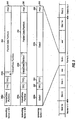
- FIG. 3 is a diagram of a frame format and a slot format for a dedicated physical channel as defined by the W-CDMA standard.
- a different frame format is defined by the W-CDMA standard for each type of physical channel such as the downlink dedicated channel (DPCH), the downlink shared channel (DSCH), and so on.
- the data to be transmitted on each physical channel i.e., the traffic data
- Each slot is further partitioned into one or more fields used to carry a combination of traffic data, overhead data, and pilot data.
- a slot 310 includes a first data (Data1) field 320a, a second data (Data2) field 320b, as transmit power control (TPC) field 322, a transport format combination indicator (TFCI) field 324, and a pilot field 326.
- Data fields 320a and 320b are used to send traffic data (e.g., voice, packet data, messaging, or others) for the dedicated physical channel.
- Transmit power control field 322 is used to send power control information to direct the remote terminal to adjust its transmit power on the uplink either up or down to achieve the desired level of performance while minimizing interference to other remote terminals.
- Transport format combination indicator field 324 is used to send information indicative of the format (e.g., the bit rate, channelization code, and so on) of the dedicated physical channel as well as of a shared physical channel associated with the dedicated physical channel.
- Pilot field 326 is used to send pilot data for the dedicated physical channel.
- Table 1 lists some of the slot formats defined by the W-CDMA standard (version V3.1.1) for the dedicated physical channel.
- Each slot format in Table 1 defines the length (in number of bits) of each field in the slot.
- the bit rate of the dedicated physical channel can vary over a large range of values (e.g., from 15 Kbps to 1920 Kbps) and the number of bits in each slot varies correspondingly.
- a number of physical channels can be used to send data to a particular remote terminal.
- Each physical channel is channelized with an orthogonal variable spreading factor (OVSF) code having a particular spreading factor (ranging from 4 to 512 for the downlink).
- OVSF code channelizes the physical channel such that the transmission on this physical channel is orthogonal to other transmissions on other physical channels.
- the OVSF code is akin to the Walsh code used in the IS-95 system to channelize the forward link transmissions.
- the OVSF code for each physical channel is typically determined (by the network) at the start of a communication session and typically does not change during the session.
- the spreading factor corresponds to the length of the OVSF code.
- a smaller spreading factor (e.g., 4) corresponds to a shorter code length and is used for a higher data rate
- a larger spreading factor (e.g., 512) corresponds to a longer code length and is used for a lower data rate.
- Table 1 the total number of bits per slot (and thus the total number of bits available for traffic data) varies over a wide range and is dependent on the spreading factor used for the slot.
- data fields 320a and 320b allocated for traffic data in each slot can be partitioned into a voice/data partition and a packet data partition.
- the voice/data partition can be used for the voice/data to be transmitted in the slot.
- the packet data partition can be used to transmit packet data.
- the data bits for the transmission are segmented and processed, as described in further detail below.
- the voice/data payload for each slot can include any number of data bits (i.e., does not need to be a specific number of bits).
- the size of the voice/data payload can vary from slot to slot.
- the spreading factor of the OVSF code can be selected accordingly.
- the spreading factor for the OVSF code ranges from 4 to 512 and in powers of two.
- Each spreading factor and slot format is associated with a particular number of data bits that can be transmitted in a slot.
- the spreading factor can thus be used to (coarsely) select the capacity of the slot.
- the largest possible spreading factor that approximately matches that payload size is selected.
- the number of coded bits in the payload for a slot may not be equal to the number of available data bits for the selected spreading factor.
- the W-CDMA standard thus defines a rate-matching scheme whereby a number of coded bits in the payload can be punctured (i.e., deleted) or repeated such that the number of rate-matched bits is equal to the number of available bits in the slot.
- the capacity of a slot can be defined.
- a portion of the slot capacity can be used for voice/data and the remaining portion can be used for packet data.
- a "slot partition parameter" can be defined and used to identify the particular allocation (e.g., a percentage amount) of the available slot for packet data and voice/data.
- Table 2 lists the partitioning of a slot for voice/data and packet data for three different sets of spreading factors.
- the slot capacity is approximately quadrupled. A quarter of the slot capacity can then be allocated for the voice/data payload and the other three-quarter of the slot capacity can be used for packet data, as shown in the fourth column.
- the spreading factor can be further reduced to further increase the slot capacity and slot partition parameter.
- the spreading factor has lengths of powers of two and the slot capacity approximately doubles each time the spreading factor is reduced by a factor of two.
- This coarse increment in the spreading factor results in a correspondingly coarse increment in the slot partition parameter (e.g., 0%, 50%, 75%, and so on, up to 100%).
- Fine adjustment of the slot partition parameter can be achieved by use of the rate-matching mechanism defined by the W-CDMA system.
- the slot partition parameter may be defined to be any particular value (e.g., 20%, 30%, and so on).
- the voice/data payload can then be fitted into the voice/data partition by selecting the proper rate-matching parameters, as described in further detail below. The rate-matching can thus be used for fine adjustment of the slot partition parameter.
- the voice/data partition can be used for one user and the packet data partition can be used for the same or different user.
- the partitions can be mixed and matched among users.
- FIG. 3 shows the slot partitioning corresponding to two reduced spreading factors.
- the spreading factor is reduced by a factor of two (from S down to S/2) and the slot capacity is approximately doubled.
- Data fields 320a and 320b are partitioned into a voice/data partition 332 and a packet data partition 334.
- Voice/data partition 332 comprises approximately half of the slot (i.e., the left half in the example shown in FIG. 3 ) and is used for voice/data.
- Packet data partition 334 comprises the remaining half of the slot and is used for packet data.
- the spreading factor is reduced by a factor of four (from S down to S/4) and the slot capacity is approximately quadrupled.
- Data fields 320a and 320b are partitioned into a voice/data partition 342 and a packet data partition 344.
- Voice/data partition 342 comprises approximately a quarter of the slot and is used for voice/data.
- Packet data partition 344 comprises the remaining three-quarter of the slot and is used for packet data.
- Other spreading factors can also be used to provide different slot capacity and to provide different percentage allocation between voice/data and packet data (i.e., different slot partition parameter).
- the spreading factor when the spreading factor is reduced by a particular factor (e.g., two), a different slot format is used. Since the new slot format is typically associated with a different number of overhead bits, the payload capacity of the new slot is approximately (and may not be exactly) increased by the particular factor.
- the partitioning of the slot into a voice/data partition and a packet data partition can be achieved in various manners.
- the slot partition parameter is selected based on the voice/data load and the packet data load. For example, if the voice/data load is approximately equal to the packet data load, the spreading factor can be selected to be half of the value that would have been selected for just the voice/data load. Approximately half of the slot capacity is then allocated for voice/data and the other half for packet data. The voice/data and packet data can each be processed based on the selected slot partition parameter, as described in further detail below.
- the voice/data payload is processed first and mapped to the available space in the slot. Any remaining part of the slot not used for voice/data can then be used to multiplex packet data.
- the slot partition parameter is determined after the processing of the voice/data payload and based on the remaining available space in the slot. To ensure that some space is available for packet data, a smaller spreading factor can be selected.
- the rate-matching processing can be operated such that a particular number of coded bits can be generated for the voice/data payload to match the number of bit positions available in the.voice/data partition. If the payload is larger than the voice/data partition, a number of coded bits can be punctured (i.e., deleted). Alternatively, if the payload is smaller than the voice/data partition, a number of coded bits can be repeated.
- a similar rate-matching can also be performed on the packet data to match the payload to the available space in the packet data partition.
- the packet data payload can be formed to match the packet data partition.
- Other techniques to map the packet data payload to the packet data partition can also be contemplated and are within the scope of the invention.
- all channels for voice/data can be defined to have the same partition length (which does not necessarily correspond to the same payload since the processing for the channels may be different). This supports the use of a completely different transmission structure (e.g., similar to that of the HDR system) in the packet data partition.
- the partitioning of a slot and the transmission of both voice/data and packet data within the slot may provide numerous advantages.
- the voice/data and packet data can be decoupled. This decoupling may be achieved, for example, by minimizing the overlap between the two partitions.
- the decoupling of voice/data and packet data can minimize the impact of packet data on voice/data and can improve performance for both types of service.
- the slot partitions support transmission of both voice/data and packet data on the same carrier. This allows a CDM system to provide multiple types of service to users.
- the slot partitions can support multiple (and independent) channel structures for voice/data and packet data, as described in further detail below.
- Each channel structure can be specifically designed for the particular type of service being supported by that channel (e.g., different coding and interleaving schemes). Also, some CDM systems such as the W-CDMA system can be adapted (possible with a small number of changes to the existing design) to support the slot partitions of the invention.
- FIG. 4 is a simplified block diagram of a communication system 400 that can implement various aspects of the invention.
- communication system 400 is a CDMA (based) system that conforms to the W-CDMA standard, the cdma2000 standard, or some other standard or CDMA (based) design.
- a transmitter unit 410 e.g., a base station
- voice/data is sent, typically in blocks, from a voice/data source 412a to a transmit (TX) voice/data processor 414a that formats, codes, and processes the data to generate coded voice/data.
- TX transmit
- packet data is sent, typically in packets, from a packet data source 412b to a transmit packet data processor 414b that formats, codes, and processes the data to generate coded packet data.
- the coded voice/data and packet data are then provided to a TDM multiplexer 416 that multiplexes the data into one TDM data stream.
- the TDM multiplexed data can have the format shown in FIG. 3 , and is provided to a transmitter (TMTR) 418 that (digitally and analog-wise) filters, (quadrature) modulates, amplifies, and upconverts the data to generate a modulated signal.
- TMTR transmitter
- the modulated signal is then transmitted via one or more antennas 420 (only one antenna is shown in FIG. 4 ) to one or more receiver units (e.g., remote terminals).
- voice/data processor 414a and packet data processor 414b are dependent on the particular CDMA standard being implemented. The processing for the W-CDMA standard is described in further detail below.
- a transmit controller 422 can direct the operation of voice/data processor 414a and packet data processor 414b to provide the desired output data. Controller 422 can further direct the operation of TDM multiplexer 416 such that the desired TDM data stream is obtained.
- the transmitted signal is received by one or more antennas 432 (again, only one antenna is shown in FIG. 4 ) and provided to a receiver (RCVR) 434.
- the received signal(s) are amplified, filtered, downconverted, (quadrature) demodulated, and digitized to generate samples.
- the samples may be processed, e.g., digitally filtered, scaled, and so on to generate symbols.
- a TDM demultiplexer (DEMUX) 436 receives and demultiplexed the symbols and provides the voice/data symbols to a receive (RX) voice/data processor 438a and the packet data symbols to a receive packet data processor 438b.
- Each data processor 438 processes and decodes the respective received symbols in a manner complementary to the processing and coding performed at transmitter unit 410.
- the decoded data from data processors 438a and 438b is then provided to respective data sinks 440a and 440b.
- a receive controller 442 can direct the operation of TDM demultiplexer 436 such that the data symbols are properly demultiplexed and routed to the proper receive data processor. Controller 442 can further direct the operation of receive data processors 438a and 438b to properly process and decode the data symbols.
- the slot partitions, slot partition parameter, and signal processing parameters can be signaled by the transmission source (e.g., base station) to the receiving device (e.g., remote terminal) based on various signaling schemes.
- the processing information can be sent by the base station to the remote terminal (1) on a control channel (e.g., the common control physical channel (CCPCH) in the W-CDMA system), (2) in the transmission itself (e.g., in a control data field in the slot), or via some other mechanism.
- some of the processing information can be provided to the remote terminal during the session initialization stage. The remote terminal then stores the information for later use.
- the signal processing described above supports transmissions of various types of service.
- a bi-directional communication system supports two-way data transmission.
- the signal processing for the reverse direction is not shown in FIG. 4 for simplicity.
- the reverse link transmission could be common to both partitions or could be partitioned as well.
- the voice/data and packet data can be processed in various manners.
- the voice/data and packet data are processed by two (independent) processing paths that can implement two different processing schemes.
- Various signal processing schemes can be used such as, for example, CDMA, TDMA, and so on.
- Each processing path can take into account the current slot partitioning parameter and process the voice/data or packet data payload such that it can be mapped into the allocated space in the slot.
- the two signal processing schemes for voice / data and packet data can be supported by two data processors 414a and 414b at transmitter unit 410 and data processors 438a and 438b at receiver unit 430.
- the signal processing scheme for each processing path may be selected specifically for the data type being transmitted by that path.
- the signal processing defined by a particular CDMA standard e.g., W-CDMA, cdma2000, or IS-95 standard
- some other CDMA (based) design may be used.
- the signal processing defined by the same of a different CDMA standard or some other design e.g., HDR
- the HDR design is well suited for packet data and may provide improved performance over other CDMA signal processing schemes.
- the voice/data and packet data can thus be segmented, coded, rate-matched, and interleaved based on their respective signal processing schemes.
- the voice/data and packet data can be modulated using the same or two different modulation schemes.
- the modulation schemes that may be used include, for example, phase shift keying (PSK) such as quadrature PSK (QPSK) or offset-QPSK (OQPSK), quadrature amplitude modulation (QAM), orthogonal frequency division multiplexing (OFDM), and others.
- PSK phase shift keying
- QPSK quadrature PSK
- OFK orthogonal frequency division multiplexing
- OFDM orthogonal frequency division multiplexing
- the voice/data and packet data are processed based on a common signal processing scheme, which can be defined by a particular CDMA standard (e.g., W-CDMA or cdma2000 standard) or some other CDMA (based) design.
- a common signal processing scheme can be defined by a particular CDMA standard (e.g., W-CDMA or cdma2000 standard) or some other CDMA (based) design.
- different sets of parameters may be used for voice/data and packet data.
- the block length and interleaving interval for packet data may be selected to be longer than for voice/data.
- different coding schemes may be used for voice/data and packet data.
- voice/data may be coded using convolutional coding and packet data may be coded using Turbo coding.
- These different processing schemes are supported by some newer generation CDMA standards such as the W-CDMA and cdma2000 standards.
- the use of a common signal processing scheme may simplify the designs of. the transmitter unit and receiver unit.
- the voice/data and packet data are time division multiplexed together into a slot after the signal processing, as shown in FIG. 4 .
- the temporal order in which the voice/data and packet data appear at the output of TDM multiplexer 416 is approximately the temporal order in which the data is transmitted over-the-air. TDM multiplexing the voice/data and packet data after the signal processing allows for decoupling of these two data types, as described in further detail below.
- the voice/data and packet data are time division multiplexed together into a slot prior to the signal processing.
- the TDM voice/data and packet data are then processed (e.g., based on a common signal processing scheme).
- voice/data and packet data may be mixed in this embodiment, various techniques can be used to minimize the impact of packet data on voice/data. For example, for a particular base station, all channels for voice/data can be defined to have the same partition length. Additional techniques to minimize the impact of packet data on voice/data are described in further detail below.
- Improved performance may be attained if the packet data partitions for neighboring base stations (or cells) are approximately aligned in time. By minimizing the amount of overlap between the voice/data transmissions and packet data transmissions (to the extent possible), the amount of interference between the two types of transmission may be reduced, which may improve the performance of both types of transmission. Alignment of the partitions may reduce the impact of the burstiness and high data rate of packet data transmissions on voice/data transmissions.
- Time alignment of the packet data partitions in neighboring cells can be achieved by first synchronizing the timing of the cells using, for example, timing from Global Position System (GPS) satellites.
- the slot partition parameter may be selected to be approximately the same (e.g., 50%) for a given cell cluster.
- the slot can then be partitioned such that the packet data partitions for the cells in the cluster overlap as much as possible. Also, changes in the slot partition parameter may be restricted to a particular range. Signaling between the (neighboring) base stations can be used to align the packet data partitions.
- the transmit power for the voice/data partitions can be increased, the transmit power for the packet data partitions can be decreased or limited to some particular values (e.g., approximately equal to that of the voice/data partitions in the same slot, as described below), or a combination thereof.
- guard time can be provided between the voice/data partition and the packet data partition.
- the guard time can be a gap of a particular time duration in which no data of any type is transmitted.
- the transmissions on some (physical) channels can be time division multiplexed to concurrently support voice/data and packet data, and the transmissions on some other channels can be operated to support voice/data only (or possibly packet data only).
- the packet data channel structure can be designed to be consistent (e.g., orthogonal) with the legacy channel structure in order to minimize interferences between channels.
- the transmit power for packet data transmissions is adjusted to reduce the amount of fluctuation in the total aggregate transmit power from the base station.
- the burstiness and high data rate of packet data transmission can cause a large fluctuation in the total aggregate transmit power from the base station, which may then cause a large fluctuation in the amount of interference to other transmissions from this and other base stations.
- the fluctuation in the total aggregate transmit power can be reduced based on various schemes.
- FIG. 5 is a plot of the transmit power for a number of voice/data transmissions and a number of packet data transmissions from a particular base station. For each slot, the transmit power for all voice/data-only transmissions can be summed and the total aggregate voice/data transmit power can be plotted as shown in FIG. 5 . For mixed voice/data and packet data transmissions, the transmit power for all voice/data partitions can be summed, and the transmit power for all packet data partitions can also be summed. The total aggregate transmit power for the packet data partitions can be maintained to be approximately equal to the total aggregate transmit power for the voice/data partitions, as shown in FIG. 5 .
- the "equalization" of the transmit power for voice/data and packet data can be achieved at the "per transmission” level or "per base station” level.
- the transmit power for the packet data partition of each mixed transmission e.g., to a particular remote terminal
- the transmit power for the voice/data partition is maintained to be approximately equal to the transmit power for the voice/data partition. This ensures that the total aggregate transmit power for the two partitions for a number of transmissions to a number of remote terminals will be approximately equal.
- Equalization at the per transmission level may be simpler to implement than at the per base station level.
- the transmit power for the packet data partition of each mixed transmission is allowed to vary from the transmit power for the voice/data partition.
- the total aggregate transmit power from the base station for the two partitions is maintained to be approximately equal.
- a controller within the base station allocates the transmit power for the packet data partition for each mixed transmission such that equalization of the aggregate transmit power is achieved.
- FIGS. 6A and 6B are diagrams of the signal processing at transmitter unit 410 for a downlink voice/data transmission in accordance with the W-CDMA standard and a downlink packet data transmission in accordance with the HDR design.
- the downlink refers to transmission from a base station to a remote terminal (or user equipment (UE), the terminology used in the W-CDMA standard), and the uplink refers to transmission from the remote terminal to the base station.
- UE user equipment
- the signal processing for voice/data is performed by voice/data processor 414a shown in FIG. 4 .
- the upper signaling layers of the W-CDMA system support concurrent transmission of a number of transport channels, with each transport channel capable of carrying voice/data (e.g., voice, video, data, and so on) for a particular communication.
- the voice/data for each transport channel is provided, in blocks that are also referred to as transport blocks, to a respective transport channel processing section 610.
- each transport block is used to calculate cyclic redundancy check (CRC) bits, in block 612.
- CRC cyclic redundancy check
- the CRC bits are attached to the transport block and used at the receiver unit for error detection.
- a number of CRC coded blocks are then serially concatenated together, in block 614. If the total number of bits after concatenation is greater than the maximum size of a code block, the bits are segmented into a number of (equal-sized) code blocks.
- Each code block is then coded with a particular coding scheme (e.g., a convolutional code, a Turbo code) or not coded at all, in block 616.
- a particular coding scheme e.g., a convolutional code, a Turbo code
- Rate matching is then performed on the code bits, in block 618. Rate matching is performed based on a rate-matching attribute assigned by higher signaling layers. In accordance with one embodiment, the rate-matching is further performed based on the slot partition parameter that defines the voice/data partition for each slot.
- bits are repeated or punctured such that the number of bits to be transmitted for each voice/data payload matches the number of bits available in the allocated voice/data partition.
- unused bit positions can be filled with discontinuous transmission (DTX) bits, in block 620.
- the DTX bits indicate when a transmission should be turned off and are not actually transmitted.
- the unused bit positions can be advantageously assigned to the packet data partition and used for packet data transmission.
- the rate-matched bits are then interleaved in accordance with a particular interleaving scheme to provide time diversity, in block 622.
- the time interval over which interleaving is performed can be selected from a set of possible time intervals (i.e., 10 msec, 20 msec, 40 msec, or 80 msec).
- the interleaving time interval is also referred to as a transmission time interval (TTI).
- TTI is an attribute associated with each transport channel and, in accordance with the W-CDMA standard, typically does not change for the duration of a communication session.
- a "traffic" comprises the bits within one TTI for a particular transport channel.
- the traffic is segmented and mapped onto consecutive transport channel radio frames, in block 624.
- Each transport channel radio frame corresponds to a transmission over a (10 msec) radio frame period.
- a traffic may be interleaved over 1, 2, 4, or 8 radio frame periods.
- the radio frames from all active transport channel processing sections 610 are then serially multiplexed onto a coded composite transport channel (CCTrCH), in block 630.
- DTX bits may then be inserted to the multiplexed radio frames such that the number of bits to be transmitted matches the number of bits available on the physical channel(s) used for the data transmission, in block 632.
- the DTX bit positions can be advantageously used for packet data transmission.
- the bits are segmented among the physical channels, in block 634. Each physical channel can carry transport channels having different TTIs.
- the bits in each radio frame period for each physical channel are then interleaved to provide additional time diversity, in block 636.
- the interleaved physical channel radio frames are then mapped to their respective physical channels, in block 638.
- FIG. 6A also shows the signal processing at transmitter unit 410 for a downlink packet data transmission in accordance with the HDR design.
- each data packet is used to calculate CRC bits, in block 652.
- the CRC bits are attached to the packet and used at the receiver unit for error detection.
- the CRC bits, data bits, and other control bits (if any) are then formatted, in block 654.
- the formatted packet is then coded with a particular coding scheme (e.g., a convolutional code, a Turbo code), in block 656.
- the code bits are then scrambled with a scrambling sequence assigned to the remote terminal designated to receive the packet data transmission, in block 658.
- the scrambled bits are next modulated in accordance with a particular modulation scheme, in block 660.
- Various modulation schemes can be used (e.g., PSK, QPSK, and QAM) with the selected scheme being dependent, for example, on the data rate of the transmission.
- the modulation symbols are then interleaved, in block 662. Symbols may then be punctured or repeated, in block 664, to obtain the desired number of symbols.
- the symbol puncturing/repetition can also be performed based on the slot partition parameter and the allocated packet data partition.
- the symbols may then be demultiplexed and mapped onto a number physical channels, in block 666.
- FIG. 6B is a diagram of the signal processing for the physical channels.
- the voice/data for each physical channel is provided to a respective physical channel processing section 640 within data processor 414a.
- the data is converted to complex notation (i.e., inphase and quadrature components), in block 642.
- the complex data for each physical channel is then channelized (i.e., covered) with a respective channelization code (e.g., an OVSF code), in block 644, and then spread with pseudo-noise (PN) spreading codes, in block 646.
- the spread data may be scaled, in block 648, to adjust the transmit power of the voice/data transmission.
- PN pseudo-noise
- the processing for the packet data for each physical channel is performed by a respective physical channel processing section 670, which typically also performs covering, spreading, and scaling.
- the processed data from all active physical channel processing sections 640 and 670 is then provided to TDM multiplexer 416.
- TDM multiplexer 416 time division multiplexes the received data into the proper partitions in the slot.
- the subsequent signal processing to generate a modulated signal suitable for transmission to the remote terminal is known in the art and not described herein.
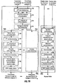
- FIGS. 7A and 7B are diagrams of the signal processing at receiver unit 430 for a downlink voice/data transmission in accordance with the W-CDMA standard and a downlink packet data transmission in accordance with the HDR design.
- the signal processing shown in FIGS. 7A and 7B is complementary to that shown in FIGS. 6A and 6B .
- the modulated signal is received, conditioned, digitized, and processed to provide symbols for each physical channel used for the transmission. Each symbol has a particular resolution (e.g., 4-bit) and corresponds to a transmitted bit.
- the symbols are provided to TDM demultiplexer 436, which provides the voice/data symbols to data processor 438a and the packet data symbols to data processor 438b.
- FIG. 7A shows the signal processing for the physical channels.
- the voice/data and packet data transmitted on each physical channel can be recovered by despreading and decoveririg the received symbols with the proper despreading and decovering codes.
- the voice/data symbols are provided to a number of physical channel processing sections 710.
- the symbols are despread with the same PN spreading codes used at the transmitter unit, in block 712, decovered with the proper channelization code, in block 714, and converted to real symbols, in block 716.
- the output from each physical channel processing section 710 comprises the coded voice/data transmitted on that physical channel.
- the processing for packet data can be achieved in similar manner by physical channel processing sections 750.
- FIG. 7B shows the processing at receiver unit 430 for a voice/data transmission on the physical channels in accordance with the W-CDMA standard.
- the symbols in each radio frame period for each physical channel are de-interleaved, in block 722, and the de-interleaved symbols from all physical channels used for the transmission are concatenated, in block 724.
- non-transmitted bits if any
- the symbols are then demultiplexed into various transport channels, in block 728.
- the radio frames for each transport channel are then provided to a respective transport channel processing section 730.
- each transport channel processing section 730 the transport channel radio frames are concatenated into traffics, in block 732.
- Each traffic includes one or more transport channel radio frames and corresponds to a particular TTI used for the transmission.
- the symbols within each traffic are de-interleaved, in block 734, and non-transmitted symbols (if any) are removed, in block 736.
- Inverse rate matching is then performed to accumulate repeated symbols and insert indication for punctured symbols, in block 738.
- Each coded block in the traffic is then decoded, in block 740 and the decoded blocks are concatenated and segmented into their respective transport blocks, in block 742.
- Each transport block is then checked for error using the CRC bits, in block 744.
- FIG. 7B also shows the signal processing at receiver unit 430 for a downlink packet data transmission in accordance with the HDR design.
- the symbols from a number of physical channels may be multiplexed together, in block 760. Erasures are then inserted for punctured bits and repeated symbols are accumulated, in block 762.
- the rate-matched symbols are de-interleaved in block 764, demodulated in block 766, descrambled in block 768, and decoded in block 770.
- the de-interleaving, demodulation, descrambling, and decoding are performed complementary to the processing performed at the transmitter unit.
- the decoded data may be formatted, in block 772, and the decoded data packet is checked for error using the CRC bits, in block 774.
- the voice/data and packet data partitions for a particular transmission can be used for a single user or can be used for two different users.
- the processing sections shown in FIGS. 7A and 7B can be used. If a remote terminal is only receiving the voice/data partition in the transmission, only the TDM demultiplexer and voice/data processor are needed. Similarly, if a remote terminal is only receiving the packet data partition in the transmission, only the TDM demultiplexer and packet data processor are needed.
- the invention can be adapted to accommodate more than two types of data.
- Each type of data can be supported by a respective partition in the slot.
- CDMA Code Division Multiple Access
- the invention may also be adapted for used in other CDMA (based) systems that conform to other CDMA standards such as, for example, the cdma2000 standard or to some other CDMA (based) designs.
- transmitter unit 410 and receiver unit 430 can be implemented in various manners.
- each data processor and controller shown in FIG. 4 can be implemented with one or more application specific integrated circuits (ASICs), digital signal processors (DSPs), programmable logic devices (PLDs), controllers, micro-controllers; microprocessors, other electronic units designed to perform the functions described herein, or a combination thereof.
- ASICs application specific integrated circuits
- DSPs digital signal processors
- PLDs programmable logic devices
- controllers micro-controllers
- microprocessors other electronic units designed to perform the functions described herein, or a combination thereof.
- an ASIC or DSP can be designed to implement multiple elements (e.g., a combination of data processors 414a and 414b and controller 422) within transmitter unit 410 or multiple elements (e.g., a combination of data processors 438a and 438b and controller 442) within receiver unit 430.
- FIGS. 6A through 7B can be implemented in hardware, software, or a combination thereof.
- the signal processing described above in FIGS. 6A through 7B can be performed by software executed on a processor.
- the source code can be stored in a memory unit and executed by a processor.
- the partitioning of the transmission interval into multiple partitions can also be implemented by dedicated hardware, software executed on a processor, or a combination thereof.
Claims (13)
- Procédé pour recevoir une transmission multiplexée par séparation temporelle (TDM), le procédé comprenant :démultiplexer une première charge utile émise dans une première partition d'un intervalle de transmission de la transmission TDM, la transmission TDM comprenant en outre une deuxième charge utile émise dans une deuxième partition de l'intervalle de transmission, l'intervalle de transmission étant un créneau dans une trame comprenant un certain nombre de créneaux ;traiter la première charge utile d'abord conformément à un premier schéma de traitement de signal ;démultiplexer la deuxième charge utile transmise dans la deuxième partition de l'intervalle de transmission ;traiter la deuxième charge utile conformément à un deuxième schéma de traitement de signal, les premier et deuxième schémas de traitement de signal utilisant des schémas différents et la première charge utile comprenant des informations de voix/données et la deuxième charge utile comprenant des paquets de données.
- Procédé selon la revendication 1, comprenant en outre :recevoir une signalisation indicative des première et deuxième partitions dans l'intervalle de transmission.
- Procédé pour recevoir une transmission multiplexée par séparation temporelle (TDM), selon la revendication 1, dans lequel les première et deuxième partitions sont définies dynamiquement en fonction d'une charge voix/données et d'une charge de paquets de données.
- Procédé pour recevoir une transmission multiplexée par séparation temporelle (TDM) selon la revendication 1, dans lequel le chevauchement entre la première charge utile et la deuxième charge utile est minimisé.
- Procédé pour recevoir une transmission multiplexée par séparation temporelle (TDM) selon la revendication 1, dans lequel la puissance d'au moins l'une des charges utiles est inférieure ou égale à la puissance d'une autre charge utile pour réduire l'impact du chevauchement.
- Procédé pour recevoir une transmission multiplexée par séparation temporelle (TDM) selon la revendication 1, dans lequel la capacité de l'intervalle de transmission est supérieure à celle requise par la première charge utile en raison d'un code de canalisation de longueur plus courte.
- Procédé selon la revendication 4, dans lequel le chevauchement entre la première charge utile et la deuxième charge utile est minimisé par un temps de garde entre la première partition et la deuxième partition de l'intervalle de transmission, et dans lequel les deuxièmes partitions des intervalles de transmission pour des sources de transmission voisines sont alignées dans le temps.
- Dispositif pour recevoir une transmission multiplexée par séparation temporelle (TDM), le dispositif comprenant :des moyens pour démultiplexer une première charge utile émise dans une première partition d'un intervalle de transmission de la transmission TDM, la transmission TDM comprenant en outre une deuxième charge utile émise dans une deuxième partition de l'intervalle de transmission, l'intervalle de transmission étant un créneau dans une trame comprenant un certain nombre de créneaux ;des moyens pour traiter la première charge utile d'abord conformément à un premier schéma de traitement de signal ;des moyens pour démultiplexer la deuxième charge utile transmise dans la deuxième partition de l'intervalle de transmission ;des moyens pour traiter la deuxième charge utile conformément à un deuxième schéma de traitement de signal, les premier et deuxième schémas de traitement de signal utilisant des schémas différents et la première charge utile comprenant des informations de voix/données et la deuxième charge utile comprenant des paquets de données.
- Dispositif selon la revendication 8, comprenant en outre :des moyens pour recevoir une signalisation indicative des première et deuxième partitions dans l'intervalle de transmission.
- Dispositif pour recevoir une transmission multiplexée par séparation temporelle (TDM), selon la revendication 8, dans lequel les première et deuxième partitions sont définies dynamiquement sur la base d'une charge voix/données et d'une charge de paquets de données.
- Dispositif pour recevoir une transmission multiplexée par séparation temporelle (TDM) selon la revendication 8, dans lequel le chevauchement entre la première charge utile et la deuxième charge utile est minimisé.
- Dispositif pour recevoir une transmission multiplexée par séparation temporelle (TDM) selon la revendication 8, dans lequel la puissance d'au moins l'une des charges utiles est inférieure ou égale à la puissance d'une autre charge utile pour réduire l'impact du chevauchement.
- Dispositif pour recevoir une transmission multiplexée par séparation temporelle (TDM) selon la revendication 8, dans lequel la capacité pour l'intervalle de transmission est plus grande que celle requise par la première charge utile en raison d'un code de canalisation de longueur plus courte et dans lequel les deuxièmes partitions des intervalles de transmission pour des sources de transmission voisines sont alignées dans le temps.
Applications Claiming Priority (2)
| Application Number | Priority Date | Filing Date | Title |
|---|---|---|---|
| US09/711,121 US6775254B1 (en) | 2000-11-09 | 2000-11-09 | Method and apparatus for multiplexing high-speed packet data transmission with voice/data transmission |
| EP01993979A EP1332569B1 (fr) | 2000-11-09 | 2001-11-07 | Procede et appareil pour multiplexer une transmission de donnees par paquets a debit eleve avec une transmission voix / donnees |
Related Parent Applications (2)
| Application Number | Title | Priority Date | Filing Date |
|---|---|---|---|
| EP01993979.2 Division | 2001-11-07 | ||
| EP01993979A Division EP1332569B1 (fr) | 2000-11-09 | 2001-11-07 | Procede et appareil pour multiplexer une transmission de donnees par paquets a debit eleve avec une transmission voix / donnees |
Publications (2)
| Publication Number | Publication Date |
|---|---|
| EP2290848A1 EP2290848A1 (fr) | 2011-03-02 |
| EP2290848B1 true EP2290848B1 (fr) | 2017-08-30 |
Family
ID=24856851
Family Applications (3)
| Application Number | Title | Priority Date | Filing Date |
|---|---|---|---|
| EP10010064.3A Expired - Lifetime EP2290848B1 (fr) | 2000-11-09 | 2001-11-07 | Procédé et appareil de multiplexage de transmission de données en paquet à haute vitesse avec transmission vocale/de données |
| EP01993979A Expired - Lifetime EP1332569B1 (fr) | 2000-11-09 | 2001-11-07 | Procede et appareil pour multiplexer une transmission de donnees par paquets a debit eleve avec une transmission voix / donnees |
| EP10004608A Withdrawn EP2207280A3 (fr) | 2000-11-09 | 2001-11-07 | Procédé et appareil de multiplexage de transmission de données en paquet à haute vitesse avec transmission vocale/de données |
Family Applications After (2)
| Application Number | Title | Priority Date | Filing Date |
|---|---|---|---|
| EP01993979A Expired - Lifetime EP1332569B1 (fr) | 2000-11-09 | 2001-11-07 | Procede et appareil pour multiplexer une transmission de donnees par paquets a debit eleve avec une transmission voix / donnees |
| EP10004608A Withdrawn EP2207280A3 (fr) | 2000-11-09 | 2001-11-07 | Procédé et appareil de multiplexage de transmission de données en paquet à haute vitesse avec transmission vocale/de données |
Country Status (18)
| Country | Link |
|---|---|
| US (2) | US6775254B1 (fr) |
| EP (3) | EP2290848B1 (fr) |
| JP (5) | JP4068455B2 (fr) |
| KR (3) | KR100930845B1 (fr) |
| CN (2) | CN101714894B (fr) |
| AT (1) | ATE515840T1 (fr) |
| AU (3) | AU2002220090B2 (fr) |
| BR (1) | BRPI0115216B1 (fr) |
| CA (1) | CA2428965C (fr) |
| ES (1) | ES2367101T3 (fr) |
| HK (1) | HK1061759A1 (fr) |
| IL (3) | IL155732A0 (fr) |
| MX (1) | MXPA03004094A (fr) |
| NO (1) | NO20032063L (fr) |
| RU (2) | RU2293441C2 (fr) |
| TW (1) | TW588529B (fr) |
| UA (1) | UA74396C2 (fr) |
| WO (1) | WO2002039595A2 (fr) |
Families Citing this family (82)
| Publication number | Priority date | Publication date | Assignee | Title |
|---|---|---|---|---|
| US8050345B1 (en) | 1999-08-09 | 2011-11-01 | Kamilo Feher | QAM and GMSK systems |
| US7548787B2 (en) | 2005-08-03 | 2009-06-16 | Kamilo Feher | Medical diagnostic and communication system |
| US7593481B2 (en) * | 1998-08-31 | 2009-09-22 | Kamilo Feher | CDMA, W-CDMA, 3rd generation interoperable modem format selectable (MFS) systems with GMSK modulated systems |
| US7415066B2 (en) * | 1998-08-10 | 2008-08-19 | Kamilo Feher | Mis-matched modulation-demodulation format selectable filters |
| US7079584B2 (en) * | 1998-08-10 | 2006-07-18 | Kamilo Feher | OFDM, CDMA, spread spectrum, TDMA, cross-correlated and filtered modulation |
| US6757334B1 (en) * | 1998-08-10 | 2004-06-29 | Kamilo Feher | Bit rate agile third-generation wireless CDMA, GSM, TDMA and OFDM system |
| US6470055B1 (en) * | 1998-08-10 | 2002-10-22 | Kamilo Feher | Spectrally efficient FQPSK, FGMSK, and FQAM for enhanced performance CDMA, TDMA, GSM, OFDN, and other systems |
| EP1110356A4 (fr) | 1998-08-31 | 2003-05-28 | Kamilo Feher | Modulation par manipulation feher et emetteurs-recepteurs avec processeurs a conformation de signal d'horloge |
| US7952511B1 (en) | 1999-04-07 | 2011-05-31 | Geer James L | Method and apparatus for the detection of objects using electromagnetic wave attenuation patterns |
| US9307407B1 (en) | 1999-08-09 | 2016-04-05 | Kamilo Feher | DNA and fingerprint authentication of mobile devices |
| US9813270B2 (en) | 1999-08-09 | 2017-11-07 | Kamilo Feher | Heart rate sensor and medical diagnostics wireless devices |
| US9373251B2 (en) | 1999-08-09 | 2016-06-21 | Kamilo Feher | Base station devices and automobile wireless communication systems |
| US7260369B2 (en) | 2005-08-03 | 2007-08-21 | Kamilo Feher | Location finder, tracker, communication and remote control system |
| FR2797736B1 (fr) * | 1999-08-19 | 2001-10-12 | Mitsubishi Electric France | Procede de configuration d'un systeme de telecommunications |
| US8463255B2 (en) | 1999-12-20 | 2013-06-11 | Ipr Licensing, Inc. | Method and apparatus for a spectrally compliant cellular communication system |
| US6775254B1 (en) * | 2000-11-09 | 2004-08-10 | Qualcomm Incorporated | Method and apparatus for multiplexing high-speed packet data transmission with voice/data transmission |
| KR100735383B1 (ko) * | 2001-02-09 | 2007-07-04 | 삼성전자주식회사 | 무선 시스템에서 데이터 서비스 장치 및 방법 |
| US7555011B2 (en) * | 2001-02-16 | 2009-06-30 | University Of Maryland, College Park | SEAMA:a source encoding assisted multiple access protocol for wireless communication |
| US20020141436A1 (en) * | 2001-04-02 | 2002-10-03 | Nokia Mobile Phone Ltd. | Downlink dedicated physical channel (DPCH) with control channel interleaved for fast control of a separate high speed downlink common channel |
| US20030021271A1 (en) * | 2001-04-03 | 2003-01-30 | Leimer Donald K. | Hybrid wireless communication system |
| HUP0401806A2 (en) * | 2001-08-30 | 2004-11-29 | Ntt Docomo Inc | Radio transmission system and method and transmission station apparatus and reception station apparatus used in the radio transmission system |
| DE10159637C1 (de) * | 2001-12-05 | 2003-08-07 | Siemens Ag | Verfahren zur Zuweisung von Übertragungskanälen in einer Mobilfunkzelle für einen Multicast-Dienst |
| US7379416B2 (en) * | 2002-03-13 | 2008-05-27 | Lsi Logic Corporation | Forward packet data channel with parallel sub-packets |
| US6967940B2 (en) * | 2002-07-19 | 2005-11-22 | Interdigital Technology Corporation | Dynamic forward error correction in UTRA systems |
| KR100952450B1 (ko) | 2002-08-01 | 2010-04-13 | 노키아 코포레이션 | 인터리빙된 다중 데이터 플로우 전송 |
| US7139274B2 (en) | 2002-08-23 | 2006-11-21 | Qualcomm, Incorporated | Method and system for a data transmission in a communication system |
| US7477618B2 (en) * | 2002-10-25 | 2009-01-13 | Qualcomm Incorporated | Method and apparatus for stealing power or code for data channel operations |
| US7680507B2 (en) * | 2002-11-04 | 2010-03-16 | Alcatel-Lucent Usa Inc. | Shared control and signaling channel for users subscribing to data services in a communication system |
| JP3679089B2 (ja) * | 2002-11-20 | 2005-08-03 | 松下電器産業株式会社 | 基地局装置および再送パケットの送信電力制御方法 |
| JP2004175052A (ja) * | 2002-11-29 | 2004-06-24 | Sony Corp | インクジェット被記録媒体、インクジェット画像形成方法及び印画物 |
| US8179833B2 (en) * | 2002-12-06 | 2012-05-15 | Qualcomm Incorporated | Hybrid TDM/OFDM/CDM reverse link transmission |
| US20040160922A1 (en) | 2003-02-18 | 2004-08-19 | Sanjiv Nanda | Method and apparatus for controlling data rate of a reverse link in a communication system |
| US8391249B2 (en) * | 2003-02-18 | 2013-03-05 | Qualcomm Incorporated | Code division multiplexing commands on a code division multiplexed channel |
| US7155236B2 (en) | 2003-02-18 | 2006-12-26 | Qualcomm Incorporated | Scheduled and autonomous transmission and acknowledgement |
| JP2005072900A (ja) * | 2003-08-22 | 2005-03-17 | Matsushita Electric Ind Co Ltd | 無線通信方法、無線通信システム、無線基地局装置及び通信端末装置 |
| US7590094B2 (en) * | 2003-09-25 | 2009-09-15 | Via Telecom Co., Ltd. | Tristate requests for flexible packet retransmission |
| US7613985B2 (en) * | 2003-10-24 | 2009-11-03 | Ikanos Communications, Inc. | Hierarchical trellis coded modulation |
| US7460524B2 (en) * | 2003-12-07 | 2008-12-02 | Lucent Technologies Inc. | Method of frame aggregation |
| US7873009B2 (en) | 2003-12-22 | 2011-01-18 | Telefonaktiebolaget L M Ericsson (Publ) | Method and system of radio communications of traffic with different characteristics |
| US7830782B2 (en) * | 2004-05-10 | 2010-11-09 | Qualcomm Incorporated | Method of using guard tones in OFDM systems for increasing robustness |
| JP2006005511A (ja) * | 2004-06-16 | 2006-01-05 | Hitachi Kokusai Electric Inc | 無線通信装置 |
| KR100689471B1 (ko) * | 2004-08-09 | 2007-03-08 | 삼성전자주식회사 | 이동통신 시스템에서 모든 주파수 대역의 서비스와 특정 주파수 대역의 서비스를 구분하는 방법 및 장치 |
| US7701898B2 (en) | 2004-09-15 | 2010-04-20 | Research In Motion Limited | Switch-in of centralised infrastructure for management for wireless communications |
| US7421004B2 (en) * | 2004-10-05 | 2008-09-02 | Kamilo Feher | Broadband, ultra wideband and ultra narrowband reconfigurable interoperable systems |
| US7359449B2 (en) * | 2004-10-05 | 2008-04-15 | Kamilo Feher | Data communication for wired and wireless communication |
| US7539214B2 (en) * | 2004-12-08 | 2009-05-26 | Motorola, Inc. | Variable reliability wireless communication transmission method and apparatus |
| US7801174B2 (en) * | 2004-12-29 | 2010-09-21 | Alcatel-Lucent Usa Inc. | Techniques for efficient control of aggregating wireless voice communications |
| US8031793B2 (en) * | 2005-01-19 | 2011-10-04 | Dumitru Mihai Ionescu | Apparatus using concatenations of signal-space codes for jointly encoding across multiple transmit antennas, and employing coordinate interleaving |
| US7787411B2 (en) * | 2005-05-10 | 2010-08-31 | Microsoft Corporation | Gaming console wireless protocol for peripheral devices |
| US7411528B2 (en) * | 2005-07-11 | 2008-08-12 | Lg Electronics Co., Ltd. | Apparatus and method of processing an audio signal |
| US10009956B1 (en) | 2017-09-02 | 2018-06-26 | Kamilo Feher | OFDM, 3G and 4G cellular multimode systems and wireless mobile networks |
| US7280810B2 (en) | 2005-08-03 | 2007-10-09 | Kamilo Feher | Multimode communication system |
| WO2007023523A1 (fr) * | 2005-08-22 | 2007-03-01 | Matsushita Electric Industrial Co., Ltd. | Dispositifs de station de base et de station mobile |
| JP5306824B2 (ja) | 2006-01-11 | 2013-10-02 | クゥアルコム・インコーポレイテッド | 無線端末のビーコン信号の使用を含むタイミングおよび/または同期に関連する方法および装置 |
| US8811369B2 (en) | 2006-01-11 | 2014-08-19 | Qualcomm Incorporated | Methods and apparatus for supporting multiple communications modes of operation |
| KR101221706B1 (ko) * | 2006-01-25 | 2013-01-11 | 삼성전자주식회사 | 고속 패킷 데이터 시스템의 순방향 링크에서 다중 입력 다중 출력 기술을 지원하는 송수신 장치 및 방법 |
| JP2009527191A (ja) * | 2006-02-17 | 2009-07-23 | アルカテル−ルーセント ユーエスエー インコーポレーテッド | ネットワーク・リソースをより効率的に使用するために構成された、エアインタフェース・エンコーダ・パケットを用いるワイヤレス通信方法 |
| EP1936851B1 (fr) * | 2006-12-18 | 2019-08-28 | Huawei Technologies Co., Ltd. | Procédé et appareil pour la transmission et la réception de données et d'informations de contrôle via une liaison ascendante dans un système de communication sans fil |
| CN103297194B (zh) * | 2007-03-07 | 2016-05-11 | 株式会社Ntt都科摩 | 正交频分复用信号接收机及接收方法 |
| US8493873B2 (en) | 2007-06-18 | 2013-07-23 | Qualcomm Incorporated | Multiplexing of sounding signals in ACK and CQI channels |
| JP2009005269A (ja) * | 2007-06-25 | 2009-01-08 | Kenwood Corp | 無線機 |
| KR101444977B1 (ko) | 2007-10-29 | 2014-09-26 | 옵티스 와이어리스 테크놀리지, 엘엘씨 | 이동국 및 송신 방법 |
| WO2009086321A1 (fr) * | 2007-12-27 | 2009-07-09 | Research In Motion Limited | Système et procédé pour réutilisation de ressource en liaision ascendante |
| US8248941B2 (en) * | 2008-02-01 | 2012-08-21 | Nokia Siemens Networks Oy | Method, apparatus and computer program for uplink scheduling in a network that employs relay nodes |
| US20090201794A1 (en) * | 2008-02-08 | 2009-08-13 | Qualcomm, Incorporated | Multiplexing devices over shared resources |
| US8595501B2 (en) | 2008-05-09 | 2013-11-26 | Qualcomm Incorporated | Network helper for authentication between a token and verifiers |
| US8498243B2 (en) * | 2008-06-11 | 2013-07-30 | Qualcomm Incorporated | Apparatus and method for channel error control of non-exclusive multiplexing for control channels |
| CN103402228B (zh) | 2008-10-31 | 2016-08-10 | 松下电器(美国)知识产权公司 | 基站装置、终端装置、通信方法和集成电路 |
| US8537750B2 (en) * | 2009-06-02 | 2013-09-17 | Futurewei Technologies, Inc. | System and method for transport block size design for multiple-input, multiple-output (MIMO) in a wireless communications system |
| US9832769B2 (en) * | 2009-09-25 | 2017-11-28 | Northwestern University | Virtual full duplex network communications |
| CN101674601B (zh) * | 2009-09-28 | 2012-04-04 | 华为技术有限公司 | 伪导频信号处理方法和装置 |
| EA017487B1 (ru) * | 2011-08-18 | 2012-12-28 | Али Магомед Оглы Аббасов | Способ приёмопередачи информации |
| US9525562B2 (en) * | 2013-05-23 | 2016-12-20 | Cahon Systems, Inc. | Modular deterministic communication terminal for remote systems |
| US9253773B2 (en) | 2013-08-29 | 2016-02-02 | Motorola Solutions, Inc. | Method and apparatus for wirelessly transacting simultaneous voice and data on adjacent timeslots |
| KR102115418B1 (ko) * | 2013-10-31 | 2020-06-05 | 삼성전자주식회사 | 무선 통신 시스템에서 장치 간 통신을 위한 신호 처리 장치 및 방법 |
| US9727516B2 (en) | 2013-12-13 | 2017-08-08 | International Business Machines Corporation | Method for power control handshaking of hot swappable components using programmable logic devices |
| TW201546115A (zh) * | 2013-12-26 | 2015-12-16 | Daikin Ind Ltd | 含有含全氟(聚)醚基之矽烷化合物的表面處理劑 |
| WO2016008147A1 (fr) | 2014-07-18 | 2016-01-21 | Qualcomm Incorporated | Amélioration de débit de données dans des dispositifs à plusieurs modules sim |
| US20160212749A1 (en) * | 2015-01-19 | 2016-07-21 | Qualcomm Incorporated | Systems and methods for use of multiple modulation and coding schemes in a physical protocol data unit |
| WO2020005195A1 (fr) * | 2018-06-25 | 2020-01-02 | Intel Corporation | Procédés et appareil pour autoriser des protocoles de planification semi-statique et/ou d'accusé de réception à faible surdébit dans un réseau local |
| WO2020132873A1 (fr) * | 2018-12-25 | 2020-07-02 | 北京小米移动软件有限公司 | Procédé et dispositif de transmission de données |
| CN112532250A (zh) * | 2019-09-19 | 2021-03-19 | 亚德诺半导体国际无限责任公司 | 用于差分信号的模块化模拟信号多路复用器 |
Family Cites Families (40)
| Publication number | Priority date | Publication date | Assignee | Title |
|---|---|---|---|---|
| JPS5763925A (en) | 1980-10-06 | 1982-04-17 | Nec Corp | Transmitter for time-division multiplex radio communication |
| US4771425A (en) * | 1984-10-29 | 1988-09-13 | Stratacom, Inc. | Synchoronous packet voice/data communication system |
| US4901307A (en) | 1986-10-17 | 1990-02-13 | Qualcomm, Inc. | Spread spectrum multiple access communication system using satellite or terrestrial repeaters |
| JPH0744511B2 (ja) | 1988-09-14 | 1995-05-15 | 富士通株式会社 | 高郊率多重化方式 |
| SE8903455D0 (sv) | 1989-10-19 | 1989-10-19 | Joakim Nelson | Dynamiska digitala foerbindelsenaet (dfn) |
| US5103459B1 (en) | 1990-06-25 | 1999-07-06 | Qualcomm Inc | System and method for generating signal waveforms in a cdma cellular telephone system |
| US5331641A (en) * | 1990-07-27 | 1994-07-19 | Transwitch Corp. | Methods and apparatus for retiming and realignment of STS-1 signals into STS-3 type signal |
| US7082106B2 (en) * | 1993-01-08 | 2006-07-25 | Multi-Tech Systems, Inc. | Computer-based multi-media communications system and method |
| CA2146472C (fr) | 1994-04-22 | 2007-10-09 | Kevin Elliott Bridgewater | Processeur de transmission inverse de signaux video par paquets avec circuits d'adresse de memoire |
| US6018528A (en) | 1994-04-28 | 2000-01-25 | At&T Corp | System and method for optimizing spectral efficiency using time-frequency-code slicing |
| JP3215018B2 (ja) * | 1994-09-09 | 2001-10-02 | 三菱電機株式会社 | 移動通信システム |
| US5570355A (en) * | 1994-11-17 | 1996-10-29 | Lucent Technologies Inc. | Method and apparatus enabling synchronous transfer mode and packet mode access for multiple services on a broadband communication network |
| US5878045A (en) * | 1996-04-26 | 1999-03-02 | Motorola, Inc. | Method and apparatus for converting data streams in a cell based communications system |
| JP3385299B2 (ja) | 1996-05-20 | 2003-03-10 | 三菱電機株式会社 | スペクトル拡散通信装置 |
| US5896375A (en) * | 1996-07-23 | 1999-04-20 | Ericsson Inc. | Short-range radio communications system and method of use |
| FI104142B (fi) | 1996-10-25 | 1999-11-15 | Nokia Mobile Phones Ltd | Radioresurssien käytön ohjausmenetelmä |
| EP0841763B1 (fr) * | 1996-10-25 | 2003-12-10 | Nokia Corporation | Procédé de contrôle de ressources radio |
| FI102703B1 (fi) | 1997-03-27 | 1999-01-29 | Nokia Telecommunications Oy | Kanavan allokointimenetelmä |
| ATE304755T1 (de) | 1997-05-02 | 2005-09-15 | Siemens Ag | Tdma/cdma nachrichtenübertragungssystem mit anpassbarer datenrate |
| EP0935363A4 (fr) | 1997-06-19 | 2005-09-07 | Toshiba Kk | Systeme de transmission avec multiplexage de donnees d'information, multiplexeur et demultiplexeur utilises a cet effet et codeur et decodeur pour correction d'erreurs |
| JP3850451B2 (ja) * | 1997-08-20 | 2006-11-29 | 三菱電機株式会社 | 移動通信システム |
| FI104527B (fi) * | 1997-09-17 | 2000-02-15 | Nokia Mobile Phones Ltd | Mukautuva radiolinkki |
| US6400723B1 (en) * | 1997-10-23 | 2002-06-04 | At&T Corp. | Multiplexing system and method for integrated voice and data transmission on network |
| US6574211B2 (en) * | 1997-11-03 | 2003-06-03 | Qualcomm Incorporated | Method and apparatus for high rate packet data transmission |
| US6363079B1 (en) * | 1997-12-31 | 2002-03-26 | At&T Corp. | Multifunction interface facility connecting wideband multiple access subscriber loops with various networks |
| WO1999053695A2 (fr) | 1998-04-14 | 1999-10-21 | Samsung Electronics Co., Ltd. | Procede de transmission de donnees dans un systeme de communication mobile |
| KR19990088052A (ko) | 1998-05-06 | 1999-12-27 | 다니엘 태그리아페리, 라이조 캐르키, 모링 헬레나 | 다중반송파광대역시디엠에이시스템에서의전력제어를제공하는방법및장치 |
| JP2000091985A (ja) | 1998-09-08 | 2000-03-31 | Hitachi Ltd | 通信システムの電力制御方法 |
| US6804251B1 (en) * | 1998-11-12 | 2004-10-12 | Broadcom Corporation | System and method for multiplexing data from multiple sources |
| JP2000183805A (ja) | 1998-12-16 | 2000-06-30 | Nec Corp | Wllシステム及びその通信方法 |
| DE50010355D1 (de) * | 1999-03-19 | 2005-06-23 | Siemens Ag | Datenübertragung mit verschachtelung und anschliessender ratenanpassung durch punktierung oder wiederholung |
| AU765329B2 (en) | 1999-04-12 | 2003-09-18 | Qualcomm Incorporated | Apparatus and method for gated transmission in a CDMA communication system |
| US6781983B1 (en) * | 1999-05-03 | 2004-08-24 | Cisco Technology, Inc. | Packet-switched telephony with circuit-switched backup |
| US6625165B1 (en) * | 1999-07-27 | 2003-09-23 | Lucent Technologies Inc. | Data link protocol for wireless systems |
| US6917603B2 (en) * | 2000-01-20 | 2005-07-12 | Nortel Networks Limited | Servicing multiple high speed data users in shared packets of a high speed wireless channel |
| DE60134716D1 (de) * | 2000-01-20 | 2008-08-21 | Nortel Networks Ltd | Adaptive rahmenstrukturen für hybride cdma / tdma systeme |
| JP2001320326A (ja) | 2000-03-03 | 2001-11-16 | Sony Corp | 通信システム、通信方法及び通信装置 |
| US6711144B1 (en) * | 2000-09-15 | 2004-03-23 | Airvana, Inc. | Multi-user communication of voice and data |
| AU1143602A (en) * | 2000-10-06 | 2002-04-15 | Aryya Communications Inc | Systems and methods for interference mitigation among multiple wlan protocols |
| US6775254B1 (en) | 2000-11-09 | 2004-08-10 | Qualcomm Incorporated | Method and apparatus for multiplexing high-speed packet data transmission with voice/data transmission |
-
2000
- 2000-11-09 US US09/711,121 patent/US6775254B1/en not_active Expired - Lifetime
-
2001
- 2001-11-06 TW TW090127538A patent/TW588529B/zh not_active IP Right Cessation
- 2001-11-07 IL IL15573201A patent/IL155732A0/xx active IP Right Grant
- 2001-11-07 AU AU2002220090A patent/AU2002220090B2/en not_active Ceased
- 2001-11-07 KR KR1020087030258A patent/KR100930845B1/ko active IP Right Grant
- 2001-11-07 MX MXPA03004094A patent/MXPA03004094A/es active IP Right Grant
- 2001-11-07 BR BRPI0115216A patent/BRPI0115216B1/pt active IP Right Grant
- 2001-11-07 AU AU2009002A patent/AU2009002A/xx active Pending
- 2001-11-07 KR KR1020037006300A patent/KR100899961B1/ko active IP Right Grant
- 2001-11-07 JP JP2002541801A patent/JP4068455B2/ja not_active Expired - Lifetime
- 2001-11-07 KR KR1020077017485A patent/KR100899962B1/ko active IP Right Grant
- 2001-11-07 EP EP10010064.3A patent/EP2290848B1/fr not_active Expired - Lifetime
- 2001-11-07 WO PCT/US2001/045563 patent/WO2002039595A2/fr active Application Filing
- 2001-11-07 AT AT01993979T patent/ATE515840T1/de not_active IP Right Cessation
- 2001-11-07 CN CN200910224573.1A patent/CN101714894B/zh not_active Expired - Lifetime
- 2001-11-07 RU RU2003117022/09A patent/RU2293441C2/ru active
- 2001-11-07 UA UA2003054118A patent/UA74396C2/uk unknown
- 2001-11-07 CA CA2428965A patent/CA2428965C/fr not_active Expired - Lifetime
- 2001-11-07 ES ES01993979T patent/ES2367101T3/es not_active Expired - Lifetime
- 2001-11-07 CN CN01821791A patent/CN100576774C/zh not_active Expired - Lifetime
- 2001-11-07 EP EP01993979A patent/EP1332569B1/fr not_active Expired - Lifetime
- 2001-11-07 EP EP10004608A patent/EP2207280A3/fr not_active Withdrawn
-
2003
- 2003-05-04 IL IL155732A patent/IL155732A/en not_active IP Right Cessation
- 2003-05-08 NO NO20032063A patent/NO20032063L/no not_active Application Discontinuation
-
2004
- 2004-06-30 HK HK04104687.6A patent/HK1061759A1/xx not_active IP Right Cessation
- 2004-07-02 US US10/884,120 patent/US8363576B2/en active Active
-
2006
- 2006-10-02 RU RU2006134821/09A patent/RU2434339C2/ru active
-
2007
- 2007-03-12 JP JP2007062300A patent/JP2007282203A/ja active Pending
-
2008
- 2008-09-03 IL IL193877A patent/IL193877A0/en unknown
-
2010
- 2010-04-20 JP JP2010096904A patent/JP5450229B2/ja not_active Expired - Lifetime
- 2010-12-06 AU AU2010249181A patent/AU2010249181A1/en not_active Abandoned
-
2012
- 2012-10-01 JP JP2012219626A patent/JP2013066182A/ja not_active Withdrawn
- 2012-12-05 JP JP2012266186A patent/JP5475094B2/ja not_active Expired - Lifetime
Non-Patent Citations (1)
| Title |
|---|
| None * |
Also Published As
Similar Documents
| Publication | Publication Date | Title |
|---|---|---|
| EP2290848B1 (fr) | Procédé et appareil de multiplexage de transmission de données en paquet à haute vitesse avec transmission vocale/de données | |
| AU2002220090A1 (en) | Method and apparatus for multiplexing high-speed packet data transmission with voice/data transmission | |
| US7302008B2 (en) | Apparatus and method for efficiently distributing energy over a packet data channel in a mobile communication system for high rate packet transmission | |
| AU2007207877B2 (en) | Method and apparatus for multiplexing high-speed packet data transmission with voice/data transmission | |
| AU2009251132A1 (en) | Method and apparatus for multiplexing high-speed packet data transmission with voice/data transmission | |
| AU2007200070A1 (en) | Method and apparatus for multiplexing high-speed packet data transmission with voice/data transmission |
Legal Events
| Date | Code | Title | Description |
|---|---|---|---|
| PUAI | Public reference made under article 153(3) epc to a published international application that has entered the european phase |
Free format text: ORIGINAL CODE: 0009012 |
|
| 17P | Request for examination filed |
Effective date: 20100921 |
|
| AC | Divisional application: reference to earlier application |
Ref document number: 1332569 Country of ref document: EP Kind code of ref document: P |
|
| AK | Designated contracting states |
Kind code of ref document: A1 Designated state(s): AT BE CH CY DE DK ES FI FR GB GR IE IT LI LU MC NL PT SE TR |
|
| GRAP | Despatch of communication of intention to grant a patent |
Free format text: ORIGINAL CODE: EPIDOSNIGR1 |
|
| INTG | Intention to grant announced |
Effective date: 20170307 |
|
| RIN1 | Information on inventor provided before grant (corrected) |
Inventor name: WILLENEGGER, SERGE Inventor name: LUNDBY, STEIN A. |
|
| GRAS | Grant fee paid |
Free format text: ORIGINAL CODE: EPIDOSNIGR3 |
|
| GRAA | (expected) grant |
Free format text: ORIGINAL CODE: 0009210 |
|
| AC | Divisional application: reference to earlier application |
Ref document number: 1332569 Country of ref document: EP Kind code of ref document: P |
|
| AK | Designated contracting states |
Kind code of ref document: B1 Designated state(s): AT BE CH CY DE DK ES FI FR GB GR IE IT LI LU MC NL PT SE TR |
|
| REG | Reference to a national code |
Ref country code: GB Ref legal event code: FG4D Ref country code: FR Ref legal event code: PLFP Year of fee payment: 17 |
|
| REG | Reference to a national code |
Ref country code: CH Ref legal event code: EP |
|
| REG | Reference to a national code |
Ref country code: AT Ref legal event code: REF Ref document number: 924560 Country of ref document: AT Kind code of ref document: T Effective date: 20170915 |
|
| REG | Reference to a national code |
Ref country code: IE Ref legal event code: FG4D |
|
| REG | Reference to a national code |
Ref country code: DE Ref legal event code: R096 Ref document number: 60150584 Country of ref document: DE |
|
| REG | Reference to a national code |
Ref country code: NL Ref legal event code: MP Effective date: 20170830 |
|
| REG | Reference to a national code |
Ref country code: AT Ref legal event code: MK05 Ref document number: 924560 Country of ref document: AT Kind code of ref document: T Effective date: 20170830 |
|
| PG25 | Lapsed in a contracting state [announced via postgrant information from national office to epo] |
Ref country code: SE Free format text: LAPSE BECAUSE OF FAILURE TO SUBMIT A TRANSLATION OF THE DESCRIPTION OR TO PAY THE FEE WITHIN THE PRESCRIBED TIME-LIMIT Effective date: 20170830 Ref country code: FI Free format text: LAPSE BECAUSE OF FAILURE TO SUBMIT A TRANSLATION OF THE DESCRIPTION OR TO PAY THE FEE WITHIN THE PRESCRIBED TIME-LIMIT Effective date: 20170830 Ref country code: AT Free format text: LAPSE BECAUSE OF FAILURE TO SUBMIT A TRANSLATION OF THE DESCRIPTION OR TO PAY THE FEE WITHIN THE PRESCRIBED TIME-LIMIT Effective date: 20170830 |
|
| PG25 | Lapsed in a contracting state [announced via postgrant information from national office to epo] |
Ref country code: GR Free format text: LAPSE BECAUSE OF FAILURE TO SUBMIT A TRANSLATION OF THE DESCRIPTION OR TO PAY THE FEE WITHIN THE PRESCRIBED TIME-LIMIT Effective date: 20171201 Ref country code: ES Free format text: LAPSE BECAUSE OF FAILURE TO SUBMIT A TRANSLATION OF THE DESCRIPTION OR TO PAY THE FEE WITHIN THE PRESCRIBED TIME-LIMIT Effective date: 20170830 |
|
| PG25 | Lapsed in a contracting state [announced via postgrant information from national office to epo] |
Ref country code: NL Free format text: LAPSE BECAUSE OF FAILURE TO SUBMIT A TRANSLATION OF THE DESCRIPTION OR TO PAY THE FEE WITHIN THE PRESCRIBED TIME-LIMIT Effective date: 20170830 |
|
| PG25 | Lapsed in a contracting state [announced via postgrant information from national office to epo] |
Ref country code: DK Free format text: LAPSE BECAUSE OF FAILURE TO SUBMIT A TRANSLATION OF THE DESCRIPTION OR TO PAY THE FEE WITHIN THE PRESCRIBED TIME-LIMIT Effective date: 20170830 |
|
| PG25 | Lapsed in a contracting state [announced via postgrant information from national office to epo] |
Ref country code: IT Free format text: LAPSE BECAUSE OF FAILURE TO SUBMIT A TRANSLATION OF THE DESCRIPTION OR TO PAY THE FEE WITHIN THE PRESCRIBED TIME-LIMIT Effective date: 20170830 |
|
| REG | Reference to a national code |
Ref country code: DE Ref legal event code: R097 Ref document number: 60150584 Country of ref document: DE |
|
| PG25 | Lapsed in a contracting state [announced via postgrant information from national office to epo] |
Ref country code: MC Free format text: LAPSE BECAUSE OF FAILURE TO SUBMIT A TRANSLATION OF THE DESCRIPTION OR TO PAY THE FEE WITHIN THE PRESCRIBED TIME-LIMIT Effective date: 20170830 |
|
| PLBE | No opposition filed within time limit |
Free format text: ORIGINAL CODE: 0009261 |
|
| STAA | Information on the status of an ep patent application or granted ep patent |
Free format text: STATUS: NO OPPOSITION FILED WITHIN TIME LIMIT |
|
| PG25 | Lapsed in a contracting state [announced via postgrant information from national office to epo] |
Ref country code: LI Free format text: LAPSE BECAUSE OF NON-PAYMENT OF DUE FEES Effective date: 20171130 Ref country code: CH Free format text: LAPSE BECAUSE OF NON-PAYMENT OF DUE FEES Effective date: 20171130 |
|
| 26N | No opposition filed |
Effective date: 20180531 |
|
| PG25 | Lapsed in a contracting state [announced via postgrant information from national office to epo] |
Ref country code: LU Free format text: LAPSE BECAUSE OF NON-PAYMENT OF DUE FEES Effective date: 20171107 |
|
| REG | Reference to a national code |
Ref country code: BE Ref legal event code: MM Effective date: 20171130 |
|
| REG | Reference to a national code |
Ref country code: IE Ref legal event code: MM4A |
|
| REG | Reference to a national code |
Ref country code: FR Ref legal event code: PLFP Year of fee payment: 18 |
|
| PG25 | Lapsed in a contracting state [announced via postgrant information from national office to epo] |
Ref country code: IE Free format text: LAPSE BECAUSE OF NON-PAYMENT OF DUE FEES Effective date: 20171107 |
|
| PG25 | Lapsed in a contracting state [announced via postgrant information from national office to epo] |
Ref country code: BE Free format text: LAPSE BECAUSE OF NON-PAYMENT OF DUE FEES Effective date: 20171130 |
|
| PG25 | Lapsed in a contracting state [announced via postgrant information from national office to epo] |
Ref country code: CY Free format text: LAPSE BECAUSE OF NON-PAYMENT OF DUE FEES Effective date: 20170830 |
|
| PG25 | Lapsed in a contracting state [announced via postgrant information from national office to epo] |
Ref country code: TR Free format text: LAPSE BECAUSE OF FAILURE TO SUBMIT A TRANSLATION OF THE DESCRIPTION OR TO PAY THE FEE WITHIN THE PRESCRIBED TIME-LIMIT Effective date: 20170830 |
|
| PG25 | Lapsed in a contracting state [announced via postgrant information from national office to epo] |
Ref country code: PT Free format text: LAPSE BECAUSE OF FAILURE TO SUBMIT A TRANSLATION OF THE DESCRIPTION OR TO PAY THE FEE WITHIN THE PRESCRIBED TIME-LIMIT Effective date: 20170830 |
|
| PGFP | Annual fee paid to national office [announced via postgrant information from national office to epo] |
Ref country code: GB Payment date: 20201029 Year of fee payment: 20 Ref country code: FR Payment date: 20201023 Year of fee payment: 20 Ref country code: DE Payment date: 20201013 Year of fee payment: 20 |
|
| REG | Reference to a national code |
Ref country code: DE Ref legal event code: R071 Ref document number: 60150584 Country of ref document: DE |
|
| REG | Reference to a national code |
Ref country code: GB Ref legal event code: PE20 Expiry date: 20211106 |
|
| PG25 | Lapsed in a contracting state [announced via postgrant information from national office to epo] |
Ref country code: GB Free format text: LAPSE BECAUSE OF EXPIRATION OF PROTECTION Effective date: 20211106 |