EP2290787A2 - Rotorwelle - Google Patents
Rotorwelle Download PDFInfo
- Publication number
- EP2290787A2 EP2290787A2 EP20100174507 EP10174507A EP2290787A2 EP 2290787 A2 EP2290787 A2 EP 2290787A2 EP 20100174507 EP20100174507 EP 20100174507 EP 10174507 A EP10174507 A EP 10174507A EP 2290787 A2 EP2290787 A2 EP 2290787A2
- Authority
- EP
- European Patent Office
- Prior art keywords
- shaft
- cylindrical portion
- end portion
- rotor
- flange
- Prior art date
- Legal status (The legal status is an assumption and is not a legal conclusion. Google has not performed a legal analysis and makes no representation as to the accuracy of the status listed.)
- Granted
Links
- 230000002093 peripheral effect Effects 0.000 claims abstract description 43
- 239000000463 material Substances 0.000 claims description 8
- 238000003825 pressing Methods 0.000 claims description 6
- 229910000975 Carbon steel Inorganic materials 0.000 claims description 5
- 239000010962 carbon steel Substances 0.000 claims description 5
- 238000005255 carburizing Methods 0.000 claims description 5
- 238000005256 carbonitriding Methods 0.000 claims description 3
- 229910001220 stainless steel Inorganic materials 0.000 claims description 3
- 230000000694 effects Effects 0.000 description 8
- 238000010586 diagram Methods 0.000 description 5
- 238000000034 method Methods 0.000 description 4
- 230000005611 electricity Effects 0.000 description 3
- 102220005308 rs33960931 Human genes 0.000 description 3
- 102220358403 c.89C>G Human genes 0.000 description 2
- 238000007796 conventional method Methods 0.000 description 2
- 230000002708 enhancing effect Effects 0.000 description 2
- 238000005259 measurement Methods 0.000 description 2
- 102200029231 rs11551768 Human genes 0.000 description 2
- 102220061996 rs786203944 Human genes 0.000 description 2
- 238000004804 winding Methods 0.000 description 2
- 229910000831 Steel Inorganic materials 0.000 description 1
- 230000001133 acceleration Effects 0.000 description 1
- 238000002485 combustion reaction Methods 0.000 description 1
- 238000001816 cooling Methods 0.000 description 1
- 238000005520 cutting process Methods 0.000 description 1
- 238000005242 forging Methods 0.000 description 1
- 238000003754 machining Methods 0.000 description 1
- 239000000203 mixture Substances 0.000 description 1
- 230000001846 repelling effect Effects 0.000 description 1
- 102200003959 rs11556986 Human genes 0.000 description 1
- 102200081478 rs121908458 Human genes 0.000 description 1
- 102220259718 rs34120878 Human genes 0.000 description 1
- 102200082816 rs34868397 Human genes 0.000 description 1
- 102220062469 rs786203185 Human genes 0.000 description 1
- 239000010959 steel Substances 0.000 description 1
Images



Classifications
-
- H—ELECTRICITY
- H02—GENERATION; CONVERSION OR DISTRIBUTION OF ELECTRIC POWER
- H02K—DYNAMO-ELECTRIC MACHINES
- H02K1/00—Details of the magnetic circuit
- H02K1/06—Details of the magnetic circuit characterised by the shape, form or construction
- H02K1/22—Rotating parts of the magnetic circuit
- H02K1/28—Means for mounting or fastening rotating magnetic parts on to, or to, the rotor structures
- H02K1/30—Means for mounting or fastening rotating magnetic parts on to, or to, the rotor structures using intermediate parts, e.g. spiders
Definitions
- the present invention relates to a rotor shaft used for a rotor of a dynamo-electric machine.
- a rotor having a magnetic body is rotatably disposed on an inner peripheral side portion of a stator having a field winding.
- the rotor includes a rotor shaft and the magnetic body mounted on the rotor shaft.
- a rotor shaft 93 is formed by connecting an inner peripheral side portion 931 and an outer peripheral side portion 933 with each other through a flange 932, and the rotor shaft 93 is integrally formed by forging or the like.
- the rotor shaft is divided radially into an inner shaft and an outer shaft, the rotor shaft can be produced easily.
- the inner shaft is shrink-fitted into the outer shaft, and both the shafts are fastened to each other to form the rotor shaft.
- the present invention has been accomplished in view of the conventional problem, and the invention provides a rotor shaft capable of sufficiently securing the fastening strength between the inner shaft and the outer shaft, obtaining the excellent anti-rotation torque, and reducing a weight of the rotor shaft.
- the present invention provides a rotor shaft used for a rotor of a dynamo-electric machine, wherein the rotor shaft is configured to be divided into a cylindrical inner shaft and an outer shaft disposed on an outer periphery of the inner shaft, the inner shaft includes a tip end portion that is an end on a side where a rotation load is input to the rotor shaft, a rear end portion having an outer diameter greater than that of the tip end portion, and a thick portion that connects the tip end portion and the rear end portion with each other and that has the same inner diameter as that of the tip end portion and has the same outer diameter as that of the rear end portion, the outer shaft includes an inner cylindrical portion having an inserting hole into which the inner shaft is inserted and fitted, a magnetic body-mounting outer cylindrical portion that is disposed on an outer peripheral side portion of the inner cylindrical portion and that mounts a magnetic body to form a magnetic circuit, and a flange that is formed radially outward from an outer periphery of the inner cylindrical portion and that connect
- the rotor shaft of the invention includes the inner shaft having the tip end portion portion, the thick portion and the rear end portion, and the outer shaft having the inner cylindrical portion, the flange and the magnetic body-mounting outer cylindrical portion.
- the inner shaft and the rotor shaft are fastened and fixed to each other by mutual pressing forces in a state that the outer peripheral surfaces of the thick portion and the rear end portion and the inner peripheral surface of the inserting hole of the inner cylindrical portion are brought into contact with each other.
- the inner shaft and the outer shaft of the rotor shaft are radially divided from each other from their contact surfaces as dividing surfaces.
- the rotor shaft can be divided at a position close to its center as close as possible, and the outer peripheral surfaces of the thick portion and the rear end portion of the inner shaft can function as surfaces that come into contact with the outer shaft (see Figs. 2 and 3A of a later-described embodiment).
- a length of a fastened portion between the inner shaft and the outer shaft in the axial direction i.e., an area of the entire fastened portion can sufficiently be secured as compared with a case where the rotor shaft is divided at a position different from that described above (see Figs. 3B to 3D of a later-described embodiment).
- a fastening strength between the inner shaft and the outer shaft in the axial direction and the circumferential direction can sufficiently be secured, and an excellent anti-rotation torque can be obtained.
- the flange of the outer shaft is disposed at a position opposed to the thick portion of the inner shaft in the radial direction.
- the flange has a high rigidity in the radial direction as compared with a portion of the outer shaft where the flange does not exist.
- the thick portion has a high rigidity in the radial direction as compared with other portion of the inner shaft. That is, in the invention, the flange having the high rigidity is disposed outside of the thick portion having the high rigidity. Therefore, the fastening strength between the inner shaft and the outer shaft in the axial direction and the circumferential direction can be enhanced, and the anti-rotation torque can further be enhanced.
- the rotor shaft capable of sufficiently securing the fastening strength between the inner shaft and the outer shaft, obtaining the excellent anti-rotation torque, and reducing the weight of the rotor shaft.
- the rotor shaft can be employed in a motor, a generator, a motor generator and the like provided in a hybrid vehicle, an electric vehicle and the like.
- an input from an internal combustion engine (engine) is transmitted to the rotor shaft at the time of acceleration, and an inertial mass of electromagnetic steel plates connected to the rotor shaft act to rotate the rotor shaft, whereby a rotation load is input to the rotor shaft.
- a side where the rotation load is input to the above-described rotor shaft means a side on which the rotation load is input.
- 85% or more of a length of the flange in its axial direction is opposed to the thick portion in the radial direction.
- the length of the flange in the axial direction opposed to the thick portion in the radial direction is less than 85%, an effect for enhancing the fastening strength between the inner shaft and the outer shaft may not sufficiently be exhibited.
- the inner shaft is shrink-fitted into the inserting hole of the inner cylindrical portion of the outer shaft.
- the inner shaft and the outer shaft can easily be fastened to each other.
- the fastening strength can sufficiently be secured.
- the shrink-fitting can be carried out in the following manner. That is, first, an inner diameter of the inserting hole of the inner cylindrical portion of the outer shaft is formed smaller than an outer diameter of the inner shaft. After the inner cylindrical portion is heated and expanded, the inner shaft is inserted into the inserting hole of the inner cylindrical portion. Thereafter, the inner cylindrical portion is cooled and shrunk, and the inner shaft is fastened into the inserting hole of the inner cylindrical portion of the outer shaft.
- the inner shaft and the outer shaft can be fastened to each other using a technique other than the shrink-fitting.
- asperities are formed on at least a portion of a contact surface of the outer peripheral surface of the thick portion with respect to the inner peripheral surface of the inserting hole of the inner cylindrical portion.
- the inner peripheral surface of the inserting hole of the inner cylindrical portion of the outer shaft comes into contact with and bites into the asperities of the outer peripheral surface of the thick portion of the inner shaft, whereby the fastening strength between the inner shaft and the outer shaft can further be enhanced.
- the asperities are formed on a portion of the contact surface of the outer peripheral surface of the thick portion where at least the thick portion and the flange are opposed to each other in the radial direction.
- the asperities of the contact surface in the outer peripheral surface of the thick portion can be formed by knurling.
- the shape of the asperities can be of twill pattern.
- the asperities can of course be formed using other machining method, and the asperities may have other shapes.
- the height of the asperities is half or less of the shrink-fitting margin because the fastening strength between the inner shaft and the outer shaft can sufficiently be obtained.
- the inner shaft is made of material that is subjected to carburizing processing or carbonitriding processing
- the outer shaft is made of carbon steel for machine structure or chromium steel.
- Examples of materials for the inner shaft, that are subjected to carburizing processing or carbonitriding processing are S15C, S20C, S30C, SCr415 and SCr420.
- Examples of carbon steel for machine structure or chromium steel constituting the outer shaft are S15C, S20C, S30C, S35C, S40C, S45C, S50C, S55C, S60C, SCr415 and SCr420.
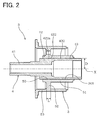
- the rotor shaft 3 of the embodiment is used for a rotor 2 of a dynamo-electric machine 1, and is divided into a cylindrical inner shaft 4 and an outer shaft 5 disposed on an outer periphery of the inner shaft 4.
- the inner shaft 4 includes a tip end portion 41 that is an end on a side where a rotation load is input to the rotor shaft 3, a rear end portion 43 having an outer diameter greater than that of the tip end portion 41, and a thick portion 42 that connects the tip end portion 41 and the rear end portion 43 in the radial direction.
- the thick portion 42 has the same inner diameter as that of the tip end portion 41, and has the same outer diameter as that of the rear end portion 43.
- the outer shaft 5 includes an inner cylindrical portion 51 having an inserting hole 50 into which the inner shaft 4 is inserted and fitted, a magnetic body-mounting outer cylindrical portion 53 disposed on the outer peripheral side portion of the inner cylindrical portion 51 for mounting a magnetic body 54 that forms a magnetic circuit, and a flange 52 formed radially outward from the outer periphery of the inner cylindrical portion 51 and connecting the inner cylindrical portion 51 and the magnetic body-mounting outer cylindrical portion 53 with each other.
- the inner shaft 4 and the outer shaft 5 are fastened and fixed to each other by mutual pressing forces in a state that outer peripheral surfaces 422 and 432 of the thick portion 42 and the rear end portion 43 and an inner peripheral surface 501 of the inserting hole 50 of the inner cylindrical portion 51 are brought into contact with each other.
- the flange 52 of the outer shaft 5 is disposed at a position opposed to the thick portion 42 of the inner shaft 4 in the radial direction.
- the dynamo-electric machine 1 of the embodiment is provided in a hybrid vehicle, an electric vehicle and the like.
- the dynamo-electric machine 1 is a motor mainly used for a driving operation.
- the dynamo-electric machine 1 may be a generator mainly used for generating electricity, or a motor generator used both for generating electricity and for the driving operation.
- the rotor shaft 3 is divided into the cylindrical inner shaft 4 and the outer shaft 5 disposed on the outer periphery of the inner shaft 4.
- a dividing position thereof is a position separated from a center X of the rotor shaft 3 by a distance D.
- a cross section of the inner shaft 4 is of a cylindrical shape, and the inner shaft 4 is rotatably disposed in a housing 11 through bearings 14 provided on outer peripheral surfaces of both ends in the axial direction.
- the inner shaft 4 includes the tip end portion 41, the thick portion 42 and the rear end portion 43.
- a thickness of the thick portion 42 is greater than those of the tip end portion 41 and the rear end portion 43.
- An outer diameter of the tip end portion 41 is smaller than those of the thick portion 42 and the rear end portion 43.
- the outer diameters of the thick portion 42 and the rear end portion 43 are substantially the same.
- the inner diameters of the tip end portion 41 and the thick portion 42 are substantially the same, and are smaller than that of the rear end portion 43.
- the outer shaft 5 includes the inner cylindrical portion 51, the flange 52 and the magnetic body-mounting outer cylindrical portion 53.
- the magnetic body-mounting outer cylindrical portion 53 has a circular cross section, and is provided on the side of the outer periphery of the flange 52 formed radially outwardly from the outer periphery of the inner cylindrical portion 51.
- the magnetic body 54 for forming the magnetic circuit in the dynamo-electric machine 1 is mounted on an outer peripheral surface of the magnetic body-mounting outer cylindrical portion 53.
- the flange 52 of the outer shaft 5 is disposed at a position opposed to the thick portion 42 of the inner shaft 4 in the radial direction.
- a region of the flange 52 not less than 85% of a length L thereof in the axial direction is opposed to the thick portion 42 in the radial direction as shown in Fig. 2 .
- the rotor 2 is formed by fastening the inner shaft 4 and the outer shaft 5 to each other, and the magnetic body 54 is mounted on the rotor 2.
- the rotor 2 is disposed on the side of an inner periphery of a stator 6 fixed to the housing 11.
- a magnetic circuit that rotates the rotor 2 or a magnetic circuit that generates electricity is formed by a field winding 61 disposed in the stator 6 and the magnetic body 54 disposed in the rotor 2.
- the inner shaft 4 is shrink-fitted into the inserting hole 50 of the inner cylindrical portion 51 of the outer shaft 5 as shown in Fig. 2 .
- This shrink-fitting is carried out in the following manner. That is, first, an inner diameter of the inserting hole 50 of the inner cylindrical portion 51 of the outer shaft 5 is formed smaller than an outer diameter of the inner shaft 4. After the inner cylindrical portion 51 is heated and expanded, the inner shaft 4 is inserted into the inserting hole 50 of the inner cylindrical portion 51. Thereafter, the inner cylindrical portion 51 is cooled and shrunk, and the inner shaft 4 is fastened to the inserting hole 50 of the inner cylindrical portion 51 of the outer shaft 5.
- the inner shaft 4 and the outer shaft 5 are fastened and fixed to each other by the mutual pressing forces in a state that the outer peripheral surfaces 422 and 432 of the thick portion 42 and the rear end portion 43 of the inner shaft 4 and the inner peripheral surface 501 of the inserting hole 50 of the inner cylindrical portion 51 in the outer shaft 5 are brought into contact with each other.
- asperities are formed on a portion of a contact surface 422a of the outer peripheral surface 422 of the thick portion 42 in the inner shaft 4 with respect to the inner peripheral surface 501 of the inserting hole 50 of the inner cylindrical portion 51 in the outer shaft 5. More specifically, asperities are formed on a part of the contact surface 422a of the outer peripheral surface 422 of the thick portion 42 where the thick portion 42 and the flange 52 are opposed to each other in the radial direction.
- the inner shaft 4 and the outer shaft 5 are fastened and fixed to each other in a state where the inner peripheral surface 501 of the inserting hole 50 of the inner cylindrical portion 51 of the outer shaft 5 bites into the asperities of the outer peripheral surface 422 of the thick portion 42 of the inner shaft 4 at the time of the shrink-fitting.
- the asperities of the contact surface 422a are formed by knurling.
- the shape of the asperities is of twill pattern.
- the height of the asperities is half or less of the shrink-fitting margin.
- SCr415 that is a material subjected to the carburizing processing is used as a material of the inner shaft 4.
- S50C that is carbon steel for machine structure is used as a material of the outer shaft 5.
- the inner shaft 4 and the outer shaft 5 are formed into desired shapes by a cutting operation.
- the rotor shaft 3 of the embodiment includes the inner shaft 4 having the tip end portion 41, the thick portion 42 and the rear end portion 43, and the outer shaft 5 having the inner cylindrical portion 51, the flange 52 and the magnetic body-mounting outer cylindrical portion 53.
- the inner shaft 4 and the outer shaft 5 are fastened and fixed to each other by the mutual pressing forces in a state that the outer peripheral surfaces 422 and 432 of the thick portion 42 and the rear end portion 43 and the inner peripheral surface 501 of the inserting hole 50 of the inner cylindrical portion 51 are brought into contact with each other.
- the inner shaft 4 and the outer shaft 5 of the rotor shaft 3 are radially divided from each other from their contact surfaces as dividing surfaces.
- the rotor shaft 3 can be divided at a position close to its center as close as possible, and the outer peripheral surfaces 422 and 432 of the thick portion 42 and the rear end portion 43 of the inner shaft 4 can function as surfaces that come into contact with the outer shaft 5.
- a length of the fastened portion between the inner shaft 4 and the outer shaft 5 in the axial direction i.e., an area of the entire fastened portion can sufficiently be secured as compared with a case where the rotor shaft 3 is divided at a position different from that described above (see Figs. 3B to 3D of a later-described second embodiment).
- the fastening strength between the inner shaft 4 and the outer shaft 5 in the axial direction and the circumferential direction can sufficiently be secured, and an excellent anti-rotation torque can be obtained.
- the flange 52 of the outer shaft 5 is disposed at a position opposed to the thick portion 42 of the inner shaft 4 in the radial direction.
- the rigidity of the flange 52 is higher than that of a portion of the outer shaft 5 where the flange 52 does not exist.
- the rigidity of the thick portion 42 is higher than that of other portion of the inner shaft 4 in the radial direction. That is, in this embodiment, the flange 52 having the high rigidity is disposed outside of the thick portion 42 having the high rigidity. Therefore, the fastening strength between the inner shaft 4 and the outer shaft 5 in the axial direction and the circumferential direction can be enhanced, and the anti-rotation torque can further be enhanced.
- the fastening strength between the inner shaft 4 and the outer shaft 5 and the anti-rotation torque can sufficiently be secured, and the weight of the entire rotor shaft 3 can be reduced.
- a region of the flange 52 not less than 85% of the length L thereof in length in the axial direction is opposed to the thick portion 42 in the radial direction. Therefore, it is possible to sufficiently exhibit the effect for enhancing the fastening strength between the inner shaft 4 and the outer shaft 5 by opposing the flange 52 and the thick portion 42 to each other.
- the inner shaft 4 is shrink-fitted into the inserting hole 50 of the inner cylindrical portion 51 of the outer shaft 5. Therefore, the inner shaft 4 and the outer shaft 5 can easily be fastened to each other. According to the configuration of the embodiment, even when the inner shaft 4 and the outer shaft 5 are fastened to each other by the shrink-fitting, the fastening strength therebetween can sufficiently be secured.
- the asperities are formed on the contact surface 422a of the outer peripheral surface 422 of the thick portion 42 with respect to the inner peripheral surface 501 of the inserting hole 50 of the inner cylindrical portion 51. More specifically, the asperities are formed on the portion of the contact surface 422a of the outer peripheral surface 422 of the thick portion 42 that is opposed to the thick portion 42 and the flange 52 in the radial direction. For this reason, the inner peripheral surface 501 of the inserting hole 50 of the inner cylindrical portion 51 of the outer shaft 5 comes into contact with and bites into the asperities of the outer peripheral surface 420 of the thick portion 42 of the inner shaft 4, whereby the fastening strength between the inner shaft 4 and the outer shaft 5 can further be enhanced.
- the fastening strength can be enhanced more effectively.
- the inner shaft 4 and the outer shaft 5 are fastened to each other by the shrink-fitting, the above effect can further be exhibited. Since the height of the asperities of the contact surface 422a is half or less of the shrink-fitting margin, the fastening strength can be enhanced reliably.
- the inner shaft 4 is made of SCr415 that is subjected to the carburizing processing
- the outer shaft 5 is made of S50C that is the carbon steel for machine structure.
- the rotor shaft 3 of the embodiment it is possible to sufficiently secure the fastening strength between the inner shaft 4 and the outer shaft 5, to obtain the excellent anti-rotation torque, and to reduce the weight of the rotor shaft.
- the anti-rotation torque of the rotor shaft when the dividing position between the inner shaft and the outer shaft is changed is evaluated.
- rotor shafts 3 (samples 11 to 14) having different dividing positions between the inner shaft 4 and the outer shaft 5 were prepared, and anti-rotation torques when shrink-fitting margins A and B (A ⁇ B) were set were measured.
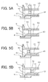
- sample 11 is the same rotor shaft 3 as that of the first embodiment as shown in Fig. 3A .
- the dividing positions of other rotor shafts 3 will be described using a constituting portion (see Fig. 3A ) of the rotor shaft 3 of the sample 11.
- the dividing position thereof is at an intermediate position of the inner cylindrical portion 51 of the outer shaft 5 as shown in Fig. 3B .
- the dividing position of the sample 13 is between the inner cylindrical portion 51 and the flange 52 of the outer shaft 5 as shown in Fig. 3C .
- the dividing position of the sample 14 is between the flange 52 and the magnetic body-mounting outer cylindrical portion 53 of the outer shaft 5 as shown in Fig. 3D .
- the anti-rotation torque was obtained by calculation.
- a friction coefficient between the inner shaft 4 and the outer shaft 5 is about 0.2.
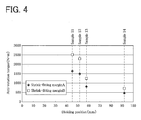
- a vertical axis shows the anti-rotation torque (N ⁇ m)
- a lateral axis shows the dividing position (mm).
- the dividing position is a position separated from the center X of the rotor shaft 3 by the distance D as shown in Figs. 3A to 3D .
- the sample 11 that is a product of the present invention has a high anti-rotation torque as compared with the samples 12 to 13 in which the inner shaft 4 and the outer shaft 5 are divided at other positions. That is, in the product of the invention, the length of the fastened portion between the inner shaft 4 and the outer shaft 5 in the axial direction (an area of the entire fastened portion) can sufficiently be secured. Therefore, it can be found that the fastening strength therebetween can sufficiently be secured and the excellent anti-rotation torque can be obtained.
- the anti-rotation torque of the rotor shaft when the position of the flange of the outer shaft is changed is evaluated.
- rotor shafts 3 (samples 21 to 24) having the flange 52 of the outer shaft 5 in different positions (lengths L in the axial direction) of were prepared, and the anti-rotation torque when the predetermined shrink-fitting margins A and B (A ⁇ B) were set in the same manner as in the second embodiment were measured.
- the sample 21 is the same rotor shaft 3 as that of the first embodiment, as shown in Fig. 5A .
- the position of the flange 52 is moved toward the tip end portion by 1.7 mm more than in the sample 21, as shown in Fig. 5B .
- the position of the flange 52 is moved toward the tip end portion by 8 mm more than in the sample 21, as shown in Fig. 5C .
- the position of the flange 52 is moved toward the rear end portion by 12.3 mm more than in the sample 21, as shown in Fig. 5D .
- the anti-rotation torque was measured by the same method as that of the second embodiment.
- the friction coefficient between the inner shaft 4 and the outer shaft 5 is about 0.2.
Landscapes
- Engineering & Computer Science (AREA)
- Power Engineering (AREA)
- Iron Core Of Rotating Electric Machines (AREA)
- Shafts, Cranks, Connecting Bars, And Related Bearings (AREA)
Applications Claiming Priority (1)
| Application Number | Priority Date | Filing Date | Title |
|---|---|---|---|
| JP2009200407A JP5639750B2 (ja) | 2009-08-31 | 2009-08-31 | ロータシャフト |
Publications (3)
| Publication Number | Publication Date |
|---|---|
| EP2290787A2 true EP2290787A2 (de) | 2011-03-02 |
| EP2290787A3 EP2290787A3 (de) | 2012-03-21 |
| EP2290787B1 EP2290787B1 (de) | 2019-02-13 |
Family
ID=43446322
Family Applications (1)
| Application Number | Title | Priority Date | Filing Date |
|---|---|---|---|
| EP10174507.3A Not-in-force EP2290787B1 (de) | 2009-08-31 | 2010-08-30 | Rotorwelle |
Country Status (4)
| Country | Link |
|---|---|
| US (1) | US8427029B2 (de) |
| EP (1) | EP2290787B1 (de) |
| JP (1) | JP5639750B2 (de) |
| CN (1) | CN102005840B (de) |
Cited By (1)
| Publication number | Priority date | Publication date | Assignee | Title |
|---|---|---|---|---|
| US20230246518A1 (en) * | 2022-02-03 | 2023-08-03 | Mahle International Gmbh | Rotor shaft for a rotor of an electric machine as well as rotor and electric machine |
Families Citing this family (3)
| Publication number | Priority date | Publication date | Assignee | Title |
|---|---|---|---|---|
| CN102738980A (zh) * | 2011-04-14 | 2012-10-17 | 侯学青 | 直流永磁无刷无位置传感器电机中绝缘转子的加工方法 |
| JP2013074736A (ja) * | 2011-09-28 | 2013-04-22 | Toyota Motor Corp | 回転電機のロータ、および、これを用いた回転電機 |
| DE102014107843B3 (de) | 2014-06-04 | 2015-11-26 | Thyssenkrupp Presta Teccenter Ag | Medientransport in Rotorwelle |
Citations (1)
| Publication number | Priority date | Publication date | Assignee | Title |
|---|---|---|---|---|
| JP2007166863A (ja) | 2005-12-16 | 2007-06-28 | Otics Corp | ロータシャフト |
Family Cites Families (11)
| Publication number | Priority date | Publication date | Assignee | Title |
|---|---|---|---|---|
| JP3351041B2 (ja) | 1993-02-26 | 2002-11-25 | 日本精工株式会社 | 転がり軸受 |
| JP3770300B2 (ja) * | 1999-03-17 | 2006-04-26 | セイコーエプソン株式会社 | 回転子およびステッピングモータ |
| DE10226572A1 (de) * | 2002-06-14 | 2004-01-08 | Robert Bosch Gmbh | Verfahren zur Herstellung eines Rotors für einen Elektromotor sowie Rotor für einen Elektromotor |
| JP2004222347A (ja) * | 2003-01-09 | 2004-08-05 | Toyota Motor Corp | 電動機の回転子 |
| JP2004336965A (ja) * | 2003-05-12 | 2004-11-25 | Denso Corp | 回転電機の回転子および磁石式交流発電機の回転子 |
| JP4158647B2 (ja) * | 2003-08-06 | 2008-10-01 | 日産自動車株式会社 | 回転電機の回転子組立治具と回転電機の回転子組立方法 |
| JP2006187061A (ja) * | 2004-12-27 | 2006-07-13 | Matsushita Electric Ind Co Ltd | スピンドルモータ |
| EP1833147B1 (de) * | 2006-03-06 | 2010-12-29 | Honda Motor Co., Ltd. | Elektromotor |
| JP4059276B2 (ja) * | 2006-03-24 | 2008-03-12 | トヨタ自動車株式会社 | 動力伝達装置およびその組立方法 |
| JP4714077B2 (ja) * | 2006-05-22 | 2011-06-29 | 株式会社オティックス | ロータシャフト |
| US20080122303A1 (en) * | 2006-11-07 | 2008-05-29 | Asmo Co., Ltd. | Direct-current motor and manufacturing method for the direct-current motor |
-
2009
- 2009-08-31 JP JP2009200407A patent/JP5639750B2/ja active Active
-
2010
- 2010-08-30 EP EP10174507.3A patent/EP2290787B1/de not_active Not-in-force
- 2010-08-31 CN CN2010102693285A patent/CN102005840B/zh not_active Expired - Fee Related
- 2010-08-31 US US12/872,493 patent/US8427029B2/en not_active Expired - Fee Related
Patent Citations (1)
| Publication number | Priority date | Publication date | Assignee | Title |
|---|---|---|---|---|
| JP2007166863A (ja) | 2005-12-16 | 2007-06-28 | Otics Corp | ロータシャフト |
Cited By (1)
| Publication number | Priority date | Publication date | Assignee | Title |
|---|---|---|---|---|
| US20230246518A1 (en) * | 2022-02-03 | 2023-08-03 | Mahle International Gmbh | Rotor shaft for a rotor of an electric machine as well as rotor and electric machine |
Also Published As
| Publication number | Publication date |
|---|---|
| EP2290787B1 (de) | 2019-02-13 |
| CN102005840B (zh) | 2013-11-06 |
| JP2011055601A (ja) | 2011-03-17 |
| CN102005840A (zh) | 2011-04-06 |
| US20110050030A1 (en) | 2011-03-03 |
| US8427029B2 (en) | 2013-04-23 |
| JP5639750B2 (ja) | 2014-12-10 |
| EP2290787A3 (de) | 2012-03-21 |
Similar Documents
| Publication | Publication Date | Title |
|---|---|---|
| US12081083B2 (en) | Rotor for an electric motor, electric motor, and method for producing a rotor | |
| US7926381B2 (en) | Idler gear for a generator | |
| EP2628949A1 (de) | Elektrischer verdichter | |
| US12301076B2 (en) | Method for sintering a multicomponent object to be sintered, electric machine, and electric vehicle | |
| EP2290787A2 (de) | Rotorwelle | |
| US20100231064A1 (en) | Balance ring for a vehicular electric machine | |
| EP1018604A3 (de) | Dynamisches Motordrucklager | |
| KR102714006B1 (ko) | 다이나모 전기 회전 기계의 회전자, 회전자를 구비한 다이나모 전기 기계 및 회전자 제조 방법 | |
| JP2011525589A (ja) | 高速回転軸のための軸配置 | |
| JP2001169487A (ja) | 永久磁石ロータ及び永久磁石ロータの製造方法 | |
| CN111095745B (zh) | 旋转电机 | |
| JP5638705B2 (ja) | 電動機の積層コア | |
| JP2011205753A (ja) | 電動機および電動機のロータの製造方法 | |
| JP4714077B2 (ja) | ロータシャフト | |
| JP5514875B2 (ja) | ロータシャフト | |
| JP6758359B2 (ja) | 回転電機 | |
| CN1253987C (zh) | 电机的转子 | |
| CN105650213A (zh) | 促动器 | |
| US20230291293A1 (en) | Method for producing an intermediate product for an electrical machine, comprising a stator laminated core and a housing part, connected thereto, of the housing | |
| JP2012019596A (ja) | 回転電機のヨークハウジング及び回転電機のヨークハウジング製造方法 | |
| US6867513B1 (en) | Electric motor | |
| US20240146132A1 (en) | Axial flux electric motor for a vehicle having rotor segment support member including a non-uniform cross-section | |
| US20080054754A1 (en) | End plate for electric motor | |
| EP4170868A1 (de) | Synchronreluktanzmotoren mit erhöhtem polausprägungsverhältnis | |
| JPH0739100A (ja) | 回転電機 |
Legal Events
| Date | Code | Title | Description |
|---|---|---|---|
| PUAI | Public reference made under article 153(3) epc to a published international application that has entered the european phase |
Free format text: ORIGINAL CODE: 0009012 |
|
| 17P | Request for examination filed |
Effective date: 20100830 |
|
| AK | Designated contracting states |
Kind code of ref document: A2 Designated state(s): AL AT BE BG CH CY CZ DE DK EE ES FI FR GB GR HR HU IE IS IT LI LT LU LV MC MK MT NL NO PL PT RO SE SI SK SM TR |
|
| AX | Request for extension of the european patent |
Extension state: BA ME RS |
|
| RIN1 | Information on inventor provided before grant (corrected) |
Inventor name: OZAWA, YUJI |
|
| RAP1 | Party data changed (applicant data changed or rights of an application transferred) |
Owner name: TOYOTA JIDOSHA KABUSHIKI KAISHA Owner name: OTICS CORPORATION |
|
| RIN1 | Information on inventor provided before grant (corrected) |
Inventor name: MIZUTANI, TATSUHIKO Inventor name: OZAWA, YUJI Inventor name: KATO, HIROKI Inventor name: YASHIRO, TAKAHISA |
|
| PUAL | Search report despatched |
Free format text: ORIGINAL CODE: 0009013 |
|
| AK | Designated contracting states |
Kind code of ref document: A3 Designated state(s): AL AT BE BG CH CY CZ DE DK EE ES FI FR GB GR HR HU IE IS IT LI LT LU LV MC MK MT NL NO PL PT RO SE SI SK SM TR |
|
| AX | Request for extension of the european patent |
Extension state: BA ME RS |
|
| RIC1 | Information provided on ipc code assigned before grant |
Ipc: H02K 1/28 20060101AFI20120213BHEP |
|
| RAP1 | Party data changed (applicant data changed or rights of an application transferred) |
Owner name: OTICS CORPORATION Owner name: TOYOTA JIDOSHA KABUSHIKI KAISHA |
|
| RIN1 | Information on inventor provided before grant (corrected) |
Inventor name: OZAWA, YUJI Inventor name: KATO, HIROKI Inventor name: MIZUTANI, TATSUHIKO Inventor name: YASHIRO, TAKAHISA |
|
| 17Q | First examination report despatched |
Effective date: 20150520 |
|
| STAA | Information on the status of an ep patent application or granted ep patent |
Free format text: STATUS: EXAMINATION IS IN PROGRESS |
|
| REG | Reference to a national code |
Ref country code: DE Ref legal event code: R079 Ref document number: 602010056937 Country of ref document: DE Free format text: PREVIOUS MAIN CLASS: H02K0001280000 Ipc: H02K0001300000 |
|
| RIC1 | Information provided on ipc code assigned before grant |
Ipc: H02K 1/30 20060101AFI20180806BHEP |
|
| GRAP | Despatch of communication of intention to grant a patent |
Free format text: ORIGINAL CODE: EPIDOSNIGR1 |
|
| STAA | Information on the status of an ep patent application or granted ep patent |
Free format text: STATUS: GRANT OF PATENT IS INTENDED |
|
| INTG | Intention to grant announced |
Effective date: 20180914 |
|
| GRAS | Grant fee paid |
Free format text: ORIGINAL CODE: EPIDOSNIGR3 |
|
| GRAA | (expected) grant |
Free format text: ORIGINAL CODE: 0009210 |
|
| STAA | Information on the status of an ep patent application or granted ep patent |
Free format text: STATUS: THE PATENT HAS BEEN GRANTED |
|
| AK | Designated contracting states |
Kind code of ref document: B1 Designated state(s): AL AT BE BG CH CY CZ DE DK EE ES FI FR GB GR HR HU IE IS IT LI LT LU LV MC MK MT NL NO PL PT RO SE SI SK SM TR |
|
| RAP1 | Party data changed (applicant data changed or rights of an application transferred) |
Owner name: OTICS CORPORATION Owner name: TOYOTA JIDOSHA KABUSHIKI KAISHA |
|
| REG | Reference to a national code |
Ref country code: GB Ref legal event code: FG4D |
|
| REG | Reference to a national code |
Ref country code: CH Ref legal event code: EP Ref country code: AT Ref legal event code: REF Ref document number: 1096772 Country of ref document: AT Kind code of ref document: T Effective date: 20190215 |
|
| REG | Reference to a national code |
Ref country code: IE Ref legal event code: FG4D |
|
| REG | Reference to a national code |
Ref country code: DE Ref legal event code: R096 Ref document number: 602010056937 Country of ref document: DE |
|
| REG | Reference to a national code |
Ref country code: LT Ref legal event code: MG4D |
|
| REG | Reference to a national code |
Ref country code: NL Ref legal event code: MP Effective date: 20190213 |
|
| PG25 | Lapsed in a contracting state [announced via postgrant information from national office to epo] |
Ref country code: NL Free format text: LAPSE BECAUSE OF FAILURE TO SUBMIT A TRANSLATION OF THE DESCRIPTION OR TO PAY THE FEE WITHIN THE PRESCRIBED TIME-LIMIT Effective date: 20190213 Ref country code: SE Free format text: LAPSE BECAUSE OF FAILURE TO SUBMIT A TRANSLATION OF THE DESCRIPTION OR TO PAY THE FEE WITHIN THE PRESCRIBED TIME-LIMIT Effective date: 20190213 Ref country code: LT Free format text: LAPSE BECAUSE OF FAILURE TO SUBMIT A TRANSLATION OF THE DESCRIPTION OR TO PAY THE FEE WITHIN THE PRESCRIBED TIME-LIMIT Effective date: 20190213 Ref country code: NO Free format text: LAPSE BECAUSE OF FAILURE TO SUBMIT A TRANSLATION OF THE DESCRIPTION OR TO PAY THE FEE WITHIN THE PRESCRIBED TIME-LIMIT Effective date: 20190513 Ref country code: PT Free format text: LAPSE BECAUSE OF FAILURE TO SUBMIT A TRANSLATION OF THE DESCRIPTION OR TO PAY THE FEE WITHIN THE PRESCRIBED TIME-LIMIT Effective date: 20190613 Ref country code: FI Free format text: LAPSE BECAUSE OF FAILURE TO SUBMIT A TRANSLATION OF THE DESCRIPTION OR TO PAY THE FEE WITHIN THE PRESCRIBED TIME-LIMIT Effective date: 20190213 |
|
| PG25 | Lapsed in a contracting state [announced via postgrant information from national office to epo] |
Ref country code: IS Free format text: LAPSE BECAUSE OF FAILURE TO SUBMIT A TRANSLATION OF THE DESCRIPTION OR TO PAY THE FEE WITHIN THE PRESCRIBED TIME-LIMIT Effective date: 20190613 Ref country code: BG Free format text: LAPSE BECAUSE OF FAILURE TO SUBMIT A TRANSLATION OF THE DESCRIPTION OR TO PAY THE FEE WITHIN THE PRESCRIBED TIME-LIMIT Effective date: 20190513 Ref country code: HR Free format text: LAPSE BECAUSE OF FAILURE TO SUBMIT A TRANSLATION OF THE DESCRIPTION OR TO PAY THE FEE WITHIN THE PRESCRIBED TIME-LIMIT Effective date: 20190213 Ref country code: LV Free format text: LAPSE BECAUSE OF FAILURE TO SUBMIT A TRANSLATION OF THE DESCRIPTION OR TO PAY THE FEE WITHIN THE PRESCRIBED TIME-LIMIT Effective date: 20190213 Ref country code: GR Free format text: LAPSE BECAUSE OF FAILURE TO SUBMIT A TRANSLATION OF THE DESCRIPTION OR TO PAY THE FEE WITHIN THE PRESCRIBED TIME-LIMIT Effective date: 20190514 |
|
| REG | Reference to a national code |
Ref country code: AT Ref legal event code: MK05 Ref document number: 1096772 Country of ref document: AT Kind code of ref document: T Effective date: 20190213 |
|
| PG25 | Lapsed in a contracting state [announced via postgrant information from national office to epo] |
Ref country code: AL Free format text: LAPSE BECAUSE OF FAILURE TO SUBMIT A TRANSLATION OF THE DESCRIPTION OR TO PAY THE FEE WITHIN THE PRESCRIBED TIME-LIMIT Effective date: 20190213 Ref country code: CZ Free format text: LAPSE BECAUSE OF FAILURE TO SUBMIT A TRANSLATION OF THE DESCRIPTION OR TO PAY THE FEE WITHIN THE PRESCRIBED TIME-LIMIT Effective date: 20190213 Ref country code: ES Free format text: LAPSE BECAUSE OF FAILURE TO SUBMIT A TRANSLATION OF THE DESCRIPTION OR TO PAY THE FEE WITHIN THE PRESCRIBED TIME-LIMIT Effective date: 20190213 Ref country code: SK Free format text: LAPSE BECAUSE OF FAILURE TO SUBMIT A TRANSLATION OF THE DESCRIPTION OR TO PAY THE FEE WITHIN THE PRESCRIBED TIME-LIMIT Effective date: 20190213 Ref country code: EE Free format text: LAPSE BECAUSE OF FAILURE TO SUBMIT A TRANSLATION OF THE DESCRIPTION OR TO PAY THE FEE WITHIN THE PRESCRIBED TIME-LIMIT Effective date: 20190213 Ref country code: DK Free format text: LAPSE BECAUSE OF FAILURE TO SUBMIT A TRANSLATION OF THE DESCRIPTION OR TO PAY THE FEE WITHIN THE PRESCRIBED TIME-LIMIT Effective date: 20190213 Ref country code: IT Free format text: LAPSE BECAUSE OF FAILURE TO SUBMIT A TRANSLATION OF THE DESCRIPTION OR TO PAY THE FEE WITHIN THE PRESCRIBED TIME-LIMIT Effective date: 20190213 Ref country code: RO Free format text: LAPSE BECAUSE OF FAILURE TO SUBMIT A TRANSLATION OF THE DESCRIPTION OR TO PAY THE FEE WITHIN THE PRESCRIBED TIME-LIMIT Effective date: 20190213 |
|
| REG | Reference to a national code |
Ref country code: DE Ref legal event code: R097 Ref document number: 602010056937 Country of ref document: DE |
|
| PG25 | Lapsed in a contracting state [announced via postgrant information from national office to epo] |
Ref country code: SM Free format text: LAPSE BECAUSE OF FAILURE TO SUBMIT A TRANSLATION OF THE DESCRIPTION OR TO PAY THE FEE WITHIN THE PRESCRIBED TIME-LIMIT Effective date: 20190213 Ref country code: PL Free format text: LAPSE BECAUSE OF FAILURE TO SUBMIT A TRANSLATION OF THE DESCRIPTION OR TO PAY THE FEE WITHIN THE PRESCRIBED TIME-LIMIT Effective date: 20190213 |
|
| PLBE | No opposition filed within time limit |
Free format text: ORIGINAL CODE: 0009261 |
|
| STAA | Information on the status of an ep patent application or granted ep patent |
Free format text: STATUS: NO OPPOSITION FILED WITHIN TIME LIMIT |
|
| PG25 | Lapsed in a contracting state [announced via postgrant information from national office to epo] |
Ref country code: AT Free format text: LAPSE BECAUSE OF FAILURE TO SUBMIT A TRANSLATION OF THE DESCRIPTION OR TO PAY THE FEE WITHIN THE PRESCRIBED TIME-LIMIT Effective date: 20190213 |
|
| 26N | No opposition filed |
Effective date: 20191114 |
|
| PG25 | Lapsed in a contracting state [announced via postgrant information from national office to epo] |
Ref country code: SI Free format text: LAPSE BECAUSE OF FAILURE TO SUBMIT A TRANSLATION OF THE DESCRIPTION OR TO PAY THE FEE WITHIN THE PRESCRIBED TIME-LIMIT Effective date: 20190213 |
|
| PG25 | Lapsed in a contracting state [announced via postgrant information from national office to epo] |
Ref country code: TR Free format text: LAPSE BECAUSE OF FAILURE TO SUBMIT A TRANSLATION OF THE DESCRIPTION OR TO PAY THE FEE WITHIN THE PRESCRIBED TIME-LIMIT Effective date: 20190213 |
|
| PG25 | Lapsed in a contracting state [announced via postgrant information from national office to epo] |
Ref country code: MC Free format text: LAPSE BECAUSE OF FAILURE TO SUBMIT A TRANSLATION OF THE DESCRIPTION OR TO PAY THE FEE WITHIN THE PRESCRIBED TIME-LIMIT Effective date: 20190213 Ref country code: LU Free format text: LAPSE BECAUSE OF NON-PAYMENT OF DUE FEES Effective date: 20190830 Ref country code: LI Free format text: LAPSE BECAUSE OF NON-PAYMENT OF DUE FEES Effective date: 20190831 Ref country code: CH Free format text: LAPSE BECAUSE OF NON-PAYMENT OF DUE FEES Effective date: 20190831 |
|
| REG | Reference to a national code |
Ref country code: BE Ref legal event code: MM Effective date: 20190831 |
|
| PG25 | Lapsed in a contracting state [announced via postgrant information from national office to epo] |
Ref country code: IE Free format text: LAPSE BECAUSE OF NON-PAYMENT OF DUE FEES Effective date: 20190830 |
|
| PG25 | Lapsed in a contracting state [announced via postgrant information from national office to epo] |
Ref country code: BE Free format text: LAPSE BECAUSE OF NON-PAYMENT OF DUE FEES Effective date: 20190831 |
|
| PG25 | Lapsed in a contracting state [announced via postgrant information from national office to epo] |
Ref country code: CY Free format text: LAPSE BECAUSE OF FAILURE TO SUBMIT A TRANSLATION OF THE DESCRIPTION OR TO PAY THE FEE WITHIN THE PRESCRIBED TIME-LIMIT Effective date: 20190213 |
|
| PG25 | Lapsed in a contracting state [announced via postgrant information from national office to epo] |
Ref country code: MT Free format text: LAPSE BECAUSE OF FAILURE TO SUBMIT A TRANSLATION OF THE DESCRIPTION OR TO PAY THE FEE WITHIN THE PRESCRIBED TIME-LIMIT Effective date: 20190213 Ref country code: HU Free format text: LAPSE BECAUSE OF FAILURE TO SUBMIT A TRANSLATION OF THE DESCRIPTION OR TO PAY THE FEE WITHIN THE PRESCRIBED TIME-LIMIT; INVALID AB INITIO Effective date: 20100830 |
|
| PG25 | Lapsed in a contracting state [announced via postgrant information from national office to epo] |
Ref country code: MK Free format text: LAPSE BECAUSE OF FAILURE TO SUBMIT A TRANSLATION OF THE DESCRIPTION OR TO PAY THE FEE WITHIN THE PRESCRIBED TIME-LIMIT Effective date: 20190213 |
|
| PGFP | Annual fee paid to national office [announced via postgrant information from national office to epo] |
Ref country code: GB Payment date: 20220707 Year of fee payment: 13 Ref country code: DE Payment date: 20220712 Year of fee payment: 13 |
|
| PGFP | Annual fee paid to national office [announced via postgrant information from national office to epo] |
Ref country code: FR Payment date: 20220709 Year of fee payment: 13 |
|
| REG | Reference to a national code |
Ref country code: DE Ref legal event code: R119 Ref document number: 602010056937 Country of ref document: DE |
|
| GBPC | Gb: european patent ceased through non-payment of renewal fee |
Effective date: 20230830 |
|
| PG25 | Lapsed in a contracting state [announced via postgrant information from national office to epo] |
Ref country code: GB Free format text: LAPSE BECAUSE OF NON-PAYMENT OF DUE FEES Effective date: 20230830 |
|
| PG25 | Lapsed in a contracting state [announced via postgrant information from national office to epo] |
Ref country code: GB Free format text: LAPSE BECAUSE OF NON-PAYMENT OF DUE FEES Effective date: 20230830 Ref country code: FR Free format text: LAPSE BECAUSE OF NON-PAYMENT OF DUE FEES Effective date: 20230831 Ref country code: DE Free format text: LAPSE BECAUSE OF NON-PAYMENT OF DUE FEES Effective date: 20240301 |