EP2290763B1 - Verbinder mit bürsten und stiften, die entlang elektrischer führungen gleiten, für haus-, unternehmens- oder industrieinstallationen - Google Patents
Verbinder mit bürsten und stiften, die entlang elektrischer führungen gleiten, für haus-, unternehmens- oder industrieinstallationen Download PDFInfo
- Publication number
- EP2290763B1 EP2290763B1 EP09757635.9A EP09757635A EP2290763B1 EP 2290763 B1 EP2290763 B1 EP 2290763B1 EP 09757635 A EP09757635 A EP 09757635A EP 2290763 B1 EP2290763 B1 EP 2290763B1
- Authority
- EP
- European Patent Office
- Prior art keywords
- guides
- connectors
- pins
- connector
- brushes
- Prior art date
- Legal status (The legal status is an assumption and is not a legal conclusion. Google has not performed a legal analysis and makes no representation as to the accuracy of the status listed.)
- Revoked
Links
- 238000009434 installation Methods 0.000 title claims description 15
- 230000005611 electricity Effects 0.000 claims description 10
- 239000007787 solid Substances 0.000 claims description 9
- RYGMFSIKBFXOCR-UHFFFAOYSA-N Copper Chemical compound [Cu] RYGMFSIKBFXOCR-UHFFFAOYSA-N 0.000 claims description 6
- 239000010949 copper Substances 0.000 claims description 6
- 229910052802 copper Inorganic materials 0.000 claims description 6
- 239000000463 material Substances 0.000 claims description 3
- 239000004020 conductor Substances 0.000 claims 2
- 229910001369 Brass Inorganic materials 0.000 description 10
- 239000010951 brass Substances 0.000 description 10
- 238000004873 anchoring Methods 0.000 description 5
- 239000002184 metal Substances 0.000 description 5
- 229910052751 metal Inorganic materials 0.000 description 5
- 238000005266 casting Methods 0.000 description 4
- 238000010276 construction Methods 0.000 description 4
- 238000010616 electrical installation Methods 0.000 description 4
- 238000004519 manufacturing process Methods 0.000 description 4
- 238000005304 joining Methods 0.000 description 3
- OKTJSMMVPCPJKN-UHFFFAOYSA-N Carbon Chemical compound [C] OKTJSMMVPCPJKN-UHFFFAOYSA-N 0.000 description 2
- 238000005553 drilling Methods 0.000 description 2
- 238000000465 moulding Methods 0.000 description 2
- 230000032258 transport Effects 0.000 description 2
- 230000006978 adaptation Effects 0.000 description 1
- 239000000853 adhesive Substances 0.000 description 1
- 230000001070 adhesive effect Effects 0.000 description 1
- 230000003796 beauty Effects 0.000 description 1
- 230000009286 beneficial effect Effects 0.000 description 1
- 229910052799 carbon Inorganic materials 0.000 description 1
- 230000000295 complement effect Effects 0.000 description 1
- 239000002131 composite material Substances 0.000 description 1
- 238000001125 extrusion Methods 0.000 description 1
- 239000003292 glue Substances 0.000 description 1
- 229910002804 graphite Inorganic materials 0.000 description 1
- 239000010439 graphite Substances 0.000 description 1
- 230000003100 immobilizing effect Effects 0.000 description 1
- 239000007937 lozenge Substances 0.000 description 1
- 150000002739 metals Chemical class 0.000 description 1
- 239000004570 mortar (masonry) Substances 0.000 description 1
- 238000005457 optimization Methods 0.000 description 1
- 230000001681 protective effect Effects 0.000 description 1
- 238000000926 separation method Methods 0.000 description 1
- 239000003826 tablet Substances 0.000 description 1
Images

Classifications
-
- H—ELECTRICITY
- H01—ELECTRIC ELEMENTS
- H01R—ELECTRICALLY-CONDUCTIVE CONNECTIONS; STRUCTURAL ASSOCIATIONS OF A PLURALITY OF MUTUALLY-INSULATED ELECTRICAL CONNECTING ELEMENTS; COUPLING DEVICES; CURRENT COLLECTORS
- H01R25/00—Coupling parts adapted for simultaneous co-operation with two or more identical counterparts, e.g. for distributing energy to two or more circuits
- H01R25/14—Rails or bus-bars constructed so that the counterparts can be connected thereto at any point along their length
- H01R25/142—Their counterparts
-
- H—ELECTRICITY
- H01—ELECTRIC ELEMENTS
- H01R—ELECTRICALLY-CONDUCTIVE CONNECTIONS; STRUCTURAL ASSOCIATIONS OF A PLURALITY OF MUTUALLY-INSULATED ELECTRICAL CONNECTING ELEMENTS; COUPLING DEVICES; CURRENT COLLECTORS
- H01R2103/00—Two poles
-
- H—ELECTRICITY
- H01—ELECTRIC ELEMENTS
- H01R—ELECTRICALLY-CONDUCTIVE CONNECTIONS; STRUCTURAL ASSOCIATIONS OF A PLURALITY OF MUTUALLY-INSULATED ELECTRICAL CONNECTING ELEMENTS; COUPLING DEVICES; CURRENT COLLECTORS
- H01R24/00—Two-part coupling devices, or either of their cooperating parts, characterised by their overall structure
- H01R24/76—Two-part coupling devices, or either of their cooperating parts, characterised by their overall structure with sockets, clips or analogous contacts and secured to apparatus or structure, e.g. to a wall
- H01R24/78—Two-part coupling devices, or either of their cooperating parts, characterised by their overall structure with sockets, clips or analogous contacts and secured to apparatus or structure, e.g. to a wall with additional earth or shield contacts
Definitions
- the present invention relates, in this case, to the novel design of connectors and electrical guides intended for mainly improving the effectiveness and simplicity or convenience when electricity needs to be transported to another point in the home, business, or companies, and workshops.
- Electrical transport is enabled by sliding connectors along fixed guides on the walls and even inserting them into the construction to be leveled, not only allowing electrical power to be transported towards the opposite side of the guide, but also using that sliding for example in apparatuses or household appliances to provide their mobility without having to disconnect the connectors from the mains, achieving through the application of this invention that electricity can be used in the desired location and as needed without requiring extension cables.
- connectors and electrical guides are designed with the aim of effectively engaging each other and consequently ensuring the safety, the transportation of an unspecified number of connectors along one or more electrical guides for driving the current and feed it to different moveable or fixed devices comprising extensions or not.
- Connectors with brushes and pins which slide along electrical guides for home, business or industrial installations to which the description relates correspond in this case to the creation and design of certain connectors initially configured from a single piece protruding from the interior of the guide profile, manufactured through molds for casting plastic and PVC, with a design on the rear part of the sliding connector so that it is fitted into the hollowed space of the profile for suitable sliding along the interior thereof.
- These connectors overall include both the female connection of each of the poles provided in all conventional male connector and the ground connection, by designing hollow housings into which several copper or brass inner connectors are fitted, so that the projecting poles that all officially approved connector necessarily carries in any connection and for any kind of domestic apparatuses or machines penetrate therein.
- a cable with connector or triple female connector always houses inside the solid piece for a better use of the space, the part of this piece inside of which the connectors, keys and poles of a male connector are housed, is fitted into the guide thereby facilitating the sliding of the connector, and the other connector part is that protruding the exact space from the electrical guide in order to allow the connector head to be housed.
- a metal spring that exerts pressure when a certain clearance is between the rear area of the connector and the inner wall of the PVC guide or profile is anchored, which has a longitudinal metallic or brass plate embedded along the guide, as a track, which in this case is directly contacted with the ground connection of the electrical installation.
- Brushes including connecting cables can also be used instead of keys, thus going the connection directly to the copper or brass connectors without using any keys nor copper cables or solid rod inserted into the molded piece.
- the guides are configured from a PVC longitudinal profile taking a rectangular almost completely closed and hollow in the interior shape, leaving an open section on one of the sides and towards a middle-height of the profile, creating a sort of slot, which occupies the entire guide length with the aim of enabling the connector forming a piece along with the sliding part to be inserted and slid along the guides continuously.
- this "C"-shaped guide generated by the open section, the recesses needed by said guide for inserting the mentioned electrical brass tracks are made, by setting a minimal clearance for their proper longitudinal installation and in order to further leave a space if appropriate occupied by adhesive material, and by fixing the tracks to the guide walls, so that these can be subsequently cut to size and according to the location or user needs, without involving the mobility of the tracks and the consequent failure or mismatch in the connection of successive guide sections.
- the link or connection of the guides to the sliding connectors, in the home, business or industrial electrical installation is carried out through the design of some plastic or PVC molded pieces tightly fitted as plugs into the rectangular space inside the guide ends fully occupying the profile section, with several through holes and threaded caps wherein a threaded stem or rod is screwed, said rod making contact with one of the tracks, when going through the thickness of the plug, by for example joining the cable corresponding to a wiring phase in the home by the opposite end of this threaded rod and via a small through hole.
- the connecting means is repeated for other phases and for the ground connection cable, this cable connection being concealed by side lids for joining the guides by using screws.
- the sliding connectors with pins are an alternative manufacturing mean to reduce electrical guides, and these are effectively valid by being connectors with similar characteristics to those described but separated into two pieces, the sliding one along the interior of the guides and the disconnectable one when separating it from the latter, due to the versatility that offers or could offer in certain and varied environments, being part of the same invention since it has the same operation as that used in connectors with brushes, these being configured by the sliding piece fitted into the guide that will also have a "C" shape because of the longitudinal slot, the sliding piece minimally exceeding the guide longitudinal slot, and being manufactured in the same way that the sliding connectors with brushes through molds for casting PVC.
- Three housing slots or three holes being enabled are provided, although as the aim is to reduce the dimensions of the guide to the maximum and from there that the connector can be detached from the sliding piece, it will be preferable to use equidistantly arranged slots, thus significantly reducing the guide longitudinal slot.
- Such slots are located in the front face of the piece going through it from side to side, leaving then a space for housing three connectors with pins, one for each electrical phase and in the centre for the ground connection, being screwed to the rear part of the piece, forming a 90° angle when are configured, some vertical pins being joined to screws as squares at different heights in each of them, whereby these will have a through hole in the lower end and will be perfectly joined to the vertical wall of the three mentioned connectors, to which other three pins that in addition of being squares could be straight are connected through the front face of the sliding piece, thus enabling the connection of the pins by the opposite end to conventional female connectors of two poles with ground connection, since the separation of the pins matches that of the connector, and the pins will also be drilled and tightly screwed to the connectors of the female connector detachable when is pulled out, thus making the pins simultaneously protrude, whereby the connection area is concealed by a hollow box with an outer shoulder that fits into the thickness of the protruding area
- Electrical guides for sliding connectors are embodied by pins through extruded PVC profiles, also in two pieces here assembled and resulting in a guide longitudinally open slot at one side along which the horizontal section of the "T" forming the sliding piece with slots and pins slides.
- An extruded profile for the top of the guide is manufactured with a section having on the rear side a vertical section broken towards the interior at an approximate middle-height, and vertically down again up to level with the lower piece of the guide, a solid form with longitudinal housings designed for anchoring the electrical brass tracks separately and staggered located occupying the entire top of the described section in order to contact each pin with its corresponding height by sliding through thereof along the entire guide.
- the piece of the bottom of the guide arranges several walls or vertical sections in the rear side, sections of which are assembled to the sidewall of the upper piece of the guide, and both sides of each piece making up the electrical guides being crisscrossly fitted, connected to the general mains in the same way as the guides and sliding connectors with brushes and installed in the wall or ceiling in the same way as the latter.
- Both ones and others connectors include one or more warning lights indicating the presence or absence of current in the connectors, being anchored anywhere in the connector or sliding piece of a single or independent piece, and a casual or temporary switch or connecting or disconnecting plug of the guide with its corresponding energy saving can also be, further included in all the guides, mounted as initial sections directly connected to the general installation, thereby providing the user the entire possibility of choosing guides with or without plug for cases wherein continuous connection is required or in those in which its use results more or less convenient, as appropriate.
- a series of connectors with brushes which slide along an upper guide and with more reduced female connector integrated therein is jointly and globally offered in the same manner and for the same reason of being selectable by the user, or on the other hand, guides smaller in size with conventional connectors adapted and detachable from the sliding piece, being in these cases a female connector with greater depth in the head and in the poles of a male connector, and the two poles do not penetrate inside the sliding piece and guide, as happens in connectors with brushes, resulting in guides more practical in some cases and others in another, as well as connectors of a single piece in some applications or detachable connectors in others, providing for the invention greater versatility and advantages in different uses, which may launch into the market as described in detail in the description or combining a connecting means through brushes for sliding pieces with pins and viceversa whenever results more beneficial for the user or for a manufacturing much more varied and adapted to optimization requirements officially approved in the field of electrical power or home, businesses and industrial general installations, by generally adding one more housing to the connectors and designing the connection for a
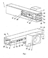
- these connectors with brushes and pins which slide along guides in home, business or industry installations (1), are configured from a sliding piece (4) joined to a first female connector (2) by providing a space for housing the poles of a male connector and of the connector head itself respectively, making up the piece (4) and the first female connector (2).
- Some electrical brushes (8) are installed at the top and bottom of the sliding piece (4) and in the interior of the guide (6) such that these are adhered to the piece (4), which have current cables (10) serving as a link between the brushes (8) and some brass inner connectors (11) contained inside the sliding piece (4), electricity fluidly passing through the brushes (8) to cables (10) and inner connectors (11) for transporting it towards the poles of a male connector, thus reaching the electrical power coming channeled into brass tracks (13), which are in turn connected to the mains or general electrical installation.
- the necessary first female connectors (2) are then engaged and inserted into the guide (6), being the guides (6) a single "C"-shaped piece profile with an open slot (14) along which the horizontal section (16) of the first female connector (2) connected to the sliding piece (4) slides, the aforementioned guides (6) besides having a top (18) and bottom (19) housing in the lower ends of the guide (6) for inserting the tracks (13), in proximity to the housing (20) made in the guide (6) at the inner wall of its rear part, at a middle-height, leading to the location of another track (13), in this case for the ground connection.
- second female connectors (3) adapted based on a conventional female connector officially approved with a design including a protective box (21), coupled with the second female connector (3), which conceals the connections of some second pins (22) which are connected, by one of its ends, to the second female connector (3) are achieved.
- a hollowed notch (23) fitting into the horizontal section (17) of an independent sliding piece (5) carrying the second female connector (3) is arranged, this independent sliding piece (5) being slid inside some guides (7).
- the independent sliding piece (5) is configured taking the form of a "T" arranged horizontally to the section (17), produced through molds for casting PVC and with equidistant slots (24) fully going through the independent sliding piece (5) from the front to the rear part, wherein brass square connectors (12) are housed occupying the lower half of the slots (24), the ones on the sides for both electrical phases and the central one reserved for the ground connection.
- each second pin (22) is connected to the corresponding square connector (12), installed inside the slots (24), the vertical area of the connector (12) being joined by screws to the rear face of the independent sliding piece (5), the screws passing before and going through the lower hole of some square first pins (9), the vertical first pins (9) thus properly coupled to connectors (12).are fitted and immobilized all the time, thus achieving a safe and adequate contact with the tracks (25) adhered inside the guides (7) along which the independent sliding piece (5) perfectly slides.
- the guide (7) is made into two pieces, the upper (7.1) and lower (7.2) flap, with PVC profiling, the assembly of the two pieces forming a "C" providing the longitudinally open slot (15) at a middle-height of the guide (7).
- the flap (7.1) is subsequently created in a vertical section with a central slit, breaking at its top into a perpendicular section and housing therein three staggered housings (26) wherein tracks (25) are inserted.
- All this series of female connectors (2) and (3) with guides (6) and (7) provide overall a novel and useful invention that allows the possibility of transporting the current to all female connectors (2) and (3) and sliding pieces (4) and (5) by circulating 1 through the open slots (14) and (15), the application or applications being installed in walls and ceilings in a practical and simple manner.
Landscapes
- Connector Housings Or Holding Contact Members (AREA)
- Electric Cable Arrangement Between Relatively Moving Parts (AREA)
- Manufacturing Of Electrical Connectors (AREA)
- Connections Arranged To Contact A Plurality Of Conductors (AREA)
Claims (4)
- Verbinder mit Bürsten und Stiften, der entlang Führungen für Haus-, Gewerbe- oder Industrieinstallationen (1) gleitet und Führungen (6, 7) umfasst, wobei die Führungen (6, 7) sich in Längsrichtung erstreckende Ausnehmungen umfassen, die in ihrem Inneren elektrische Leiterschienen haben, um elektrischen Strom mit Hilfe elektrischer Stecker oder Verbinder abzunehmen, die in die Führungen eingefügt sind, dadurch gekennzeichnet, dass- die elektrischen Leiterschienen aus elektrischen Bahnen (13, 25) bestehen, die in den Ausnehmungen angeordnet sind, mit einer flachen Geometrie, so dass sie einen flachen elektrischen Kontakt bieten;- der Verbinder ein Gleitstück (4, 5) umfasst, das dauerhaft in die Führungen (6, 7) eingeführt ist und in dauerhaftem elektrischen Kontakt mit den elektrischen Bahnen (13, 25) mit Hilfe von Bürsten (8) oder ersten Stiften (9) mit einer flachen Geometrie steht, die einen dauerhaften flachen Kontakt mit den Bahnen (13, 25) im Inneren der Führungen (6, 7) herstellen; und- der Kontakt der Bürsten (8) oder ersten Stifte (9) mit den Bahnen (13, 25) durch fortwährende Druckausübung erfolgt.
- Verbinder mit Bürsten und Stiften, der entlang Führungen für Haus-, Gewerbe- oder Industrieinstallationen (1) gleitet, nach Anspruch 1, wobei der Verbinder den Aufbau eines ersten Buchsenverbinders (2) hat, dadurch gekennzeichnet, dass das Gleitstück (4) ein integraler Teil des ersten Buchsenverbinders (2) ist, mit dem es durch einen horizontalen Abschnitt (16) verbunden ist, was bedeutet, dass der erste Buchsenverbinder (2) dauerhaft in das Innere der Führung (6) in dauerhaftem elektrischen Kontakt mit den Bahnen (13) eingefügt ist, wobei das Gleitstück (4) Bürsten (8) umfasst, die mit inneren Verbindern (11) verbunden sind; die inneren Verbinder (11) mit den Standardanschlüssen des ersten Buchsenverbinders (2) verbunden sind; die Bürsten (8) mit den inneren Verbindern (11) mit Hilfe einer Auswahl von Kupfervolldrähten und Führungsnasen oder Leitungskabeln (10) verbunden sind; die Bürsten (8) einen Kontakt mit den Bahnen (13) herstellen, die sich in den Ausnehmungen (18, 19) befinden; die Erdungsverbindung durch den Kontakt einer Metallfeder mit der Bahn (13), die sich in der Ausnehmung (20) befindet, gelöst ist und elektrischen Erdungsstrom leitet; und die Metallfeder an ein Ende eines mit einem Innengewinde versehenen Stabes geschraubt ist, der mit seinem anderen Ende mit der Standardleiste des ersten Buchsenverbinders (2) verbunden ist.
- Verbinder mit Bürsten und Stiften, der entlang Führungen für Haus-, Gewerbe- oder Industrieinstallationen (1) gleitet, nach Anspruch 1, wobei der Verbinder einen Aufbau eines zweiten Buchsenverbinders (3) umfasst, dadurch gekennzeichnet, dass der zweite Buchsenverbinder (3) dazu eingerichtet ist, mit einem Kasten (21) verbunden zu werden; das Gleitstück ein unabhängiges Gleitstück (5) ist, so dass der zweite Buchsenverbinder (3) von dem unabhängigen Gleitstück (5) getrennt werden kann; das unabhängige Gleitstück (5) an zentraler Stelle äquidistante Schlitze (24) in einem horizontalen Abschnitt (17) des unabhängigen Gleitstückes (5) hat, wodurch eine Abfolge von ausgerichteten Hohlräumen erzeugt ist, in denen viereckige Verbinder (12) aufgenommen sind, und erste Stifte (9) an jedem der viereckigen Verbinder verankert sind; die ersten Stifte (9) in fortwährendem Kontakt mit Bahnen (25) sind, die sich in gestaffelten Gehäusen (26) eines oberen Schenkels (7.1) befinden; der obere Schenkel (7.1) eine Führung (7) mit Hilfe einer engen und sich kreuzenden Anordnung des oberen Schenkels (7.1) mit einem unteren Schenkel (7.2) bildet; ein hohles Passstück (23) in den horizontalen Abschnitt (17) des unabhängigen Gleitstückes (5) eingefügt ist; wobei das hohle Passstück (23) von dem hinteren Teil des Kastens (21) an einer Position hervorragt, die zwischen mittlerem, oberem oder unterem Bereich gewählt ist; das hohle Passstück (23) mit dem Kasten (12) einstückig verbunden ist; der Kasten mit dem zweiten Buchsenverbinder (3) verbunden ist; und vor der verschraubten Anbringung des Kastens (21) zweite Stifte (22) mit den herkömmlichen Verbindern verbunden werden, die in dem zweiten Buchsenverbinder (3) aufgenommen sind, wodurch die zweiten Stifte (22) unbeweglich gemacht werden.
- Verbinder mit Bürsten und Stiften, der entlang Führungen für Haus-, Gewerbe- oder Industrieinstallationen (1) gleitet, gemäß den vorherigen Ansprüchen, dadurch gekennzeichnet, dass die Buchsenverbinder (2) und (3) entlang Führungen (6) und (7), die zu einem Stück und zwei Teilen oder Schenkeln (7.1) und (7.2) ausgebildet sind, gleiten, die allesamt aus einem Kunststoff- oder PVC-Material ausgebildet sind, das sich dazu eignet, der Temperatur und der Spannung der transportierten Elektrizität zu widerstehen, sämtliche Führungen (6) und (7) fortwährend einen offenen länglichen Zwischenraum mit optimierter Höhe bereitstellen, der Schlitze (14) und (15) erzeugt, die Teil beider Führungen (6) und (7) sind, die Buchsenverbinder (2) und (3), die sich vorwärts oder rückwärts bewegen, die horizontalen Abschnitte (16) und (17) in die Schlitze (14) und (15) einfügen und entlang derselben verschoben werden, wobei Bürsten (8) und erste Stifte (9) die Bahnen (13) und (25) berühren, Warnleuchten, die die Gegenwart oder Abwesenheit von Elektrizität in den Führungen (6) und (7) anzeigen, an einem beliebigen Ort in den Buchsenverbindern (2) und (3) oder den Gleitstücken (4) und (5) enthalten sind und temporär verbindende und trennende Stecker der Führung entsprechend Haus-, Gewerbe- oder Industrieinstallationen an den Anfangs- oder End-Führungsabschnitten angebracht sind.
Priority Applications (1)
| Application Number | Priority Date | Filing Date | Title |
|---|---|---|---|
| PL09757635T PL2290763T3 (pl) | 2008-06-06 | 2009-04-30 | Wtyczki ze szczoteczkami i bolcami, które przesuwają się wzdłuż prowadnic elektrycznych dla instalacji domowych, firmowych i przemysłowych |
Applications Claiming Priority (2)
| Application Number | Priority Date | Filing Date | Title |
|---|---|---|---|
| ES200801215U ES1068230Y (es) | 2008-06-06 | 2008-06-06 | Enchufes con escobillas y patillas de deslizamiento por guias electricas para instalaciones del hogar, comercio o industria |
| PCT/ES2009/000232 WO2009147256A1 (es) | 2008-06-06 | 2009-04-30 | Enchufes con escobillas y patillas de deslizamiento por guias eléctricas para instalaciones del hogar, comercio o industria |
Publications (3)
| Publication Number | Publication Date |
|---|---|
| EP2290763A1 EP2290763A1 (de) | 2011-03-02 |
| EP2290763A4 EP2290763A4 (de) | 2013-01-09 |
| EP2290763B1 true EP2290763B1 (de) | 2015-08-12 |
Family
ID=39731877
Family Applications (1)
| Application Number | Title | Priority Date | Filing Date |
|---|---|---|---|
| EP09757635.9A Revoked EP2290763B1 (de) | 2008-06-06 | 2009-04-30 | Verbinder mit bürsten und stiften, die entlang elektrischer führungen gleiten, für haus-, unternehmens- oder industrieinstallationen |
Country Status (14)
| Country | Link |
|---|---|
| US (1) | US8469726B2 (de) |
| EP (1) | EP2290763B1 (de) |
| JP (1) | JP5309214B2 (de) |
| CN (1) | CN102057542B (de) |
| AU (1) | AU2009254507A1 (de) |
| BR (1) | BRPI0913601A2 (de) |
| CA (1) | CA2724613C (de) |
| ES (2) | ES1068230Y (de) |
| IL (1) | IL209355A0 (de) |
| MA (1) | MA32443B1 (de) |
| MX (1) | MX2010012916A (de) |
| PL (1) | PL2290763T3 (de) |
| RU (1) | RU2516305C2 (de) |
| WO (1) | WO2009147256A1 (de) |
Families Citing this family (27)
| Publication number | Priority date | Publication date | Assignee | Title |
|---|---|---|---|---|
| TWI409020B (zh) * | 2010-12-23 | 2013-09-11 | Delta Electronics Inc | 資料處理設備及其電源配接機構與方法 |
| ES1077942Y (es) | 2012-09-17 | 2013-01-29 | Sist S Metalper S L | Modulo para toma de corriente |
| CN103353097B (zh) * | 2013-07-16 | 2016-03-16 | 太龙(福建)商业照明股份有限公司 | 一种灯具轨道的快速警示系统 |
| CN103956620B (zh) * | 2014-04-27 | 2017-03-08 | 相舆科技(上海)有限公司 | 一种智能家居电力连接系统 |
| ES2532296B1 (es) * | 2014-09-10 | 2016-01-15 | Universitat Politècnica De València | Sistema de carril electrificado con bases de enchufe móviles |
| US9685730B2 (en) | 2014-09-12 | 2017-06-20 | Steelcase Inc. | Floor power distribution system |
| WO2016197927A1 (en) | 2015-06-12 | 2016-12-15 | Shanutec (Shanghai) Co., Ltd. | An electrical power outlet strip |
| CN104901099B (zh) * | 2015-06-12 | 2017-06-27 | 相舆科技(上海)有限公司 | 一种家居电力连接系统 |
| US10312622B2 (en) * | 2015-07-28 | 2019-06-04 | Shanutec (Shanghai) Co., Ltd. | Movable socket assembly |
| FR3039844B1 (fr) * | 2015-08-06 | 2019-04-26 | Owwi | Piece evolutive comprenant une cloison connectable electriquement a un mur |
| CN105577096A (zh) * | 2015-12-31 | 2016-05-11 | 施国庆 | 一种光伏系统台架 |
| CN105429576A (zh) * | 2015-12-31 | 2016-03-23 | 施国庆 | 一种光伏系统台架 |
| ES2637562B1 (es) * | 2016-04-12 | 2018-02-07 | Fabricación De Material Eléctrico, S.A. | Módulo para toma de corriente deslizable |
| CN106025701B (zh) * | 2016-07-11 | 2018-09-07 | 深圳市艾特网能技术有限公司 | 用于端子插接的导向机构及端子组件 |
| RU169568U1 (ru) * | 2016-11-08 | 2017-03-23 | Акционерное общество "Научно-производственное объединение"Каскад" | Крепежная рамка для модульного соединителя с защитным корпусом |
| CN108123337B (zh) | 2016-11-28 | 2021-06-22 | 泰连公司 | 用于通信系统的电力连接器组件 |
| RU180027U1 (ru) * | 2017-06-02 | 2018-05-31 | Василий Мотелевич Оснач | Электрический соединитель |
| US10673189B2 (en) * | 2018-06-06 | 2020-06-02 | Te Connectivity Corporation | Power connector assembly for a communication system |
| CN109088285B (zh) * | 2018-08-19 | 2020-09-08 | 深圳朴方环保发展有限公司 | 一种滑动式充电接头和充电桩 |
| US10939576B2 (en) | 2018-11-28 | 2021-03-02 | Te Connectivity Corporation | Power connector assembly for a communication system |
| KR102249638B1 (ko) * | 2019-08-06 | 2021-05-07 | 양윤선 | 탈부착식 전원공급 선반거치 구조체 |
| CN111193160A (zh) * | 2020-02-15 | 2020-05-22 | 惠州市加迈电器有限公司 | 一体式旋转取电插座、壁式排插接线轨及轻型轨道式排插 |
| US11332043B2 (en) | 2020-02-25 | 2022-05-17 | Ford Global Technologies, Llc | Connector assembly for a vehicle seat |
| RU202330U1 (ru) * | 2020-10-23 | 2021-02-11 | Дмитрий Вячеславович Назаров | Электрический соединитель |
| CN112881920B (zh) * | 2021-04-12 | 2022-07-26 | 国网山东省电力公司莱芜供电公司 | 一种专用于储能电站的退运铅酸蓄电池能量管理器件 |
| CN113346298B (zh) * | 2021-05-27 | 2022-06-03 | 杭州精卓楼宇智能设备有限公司 | 一种组合式明装线槽系统 |
| CN113666041B (zh) * | 2021-08-12 | 2022-12-06 | 江阴名鸿车顶系统有限公司 | 一种与穿梭车配合的穿梭货架 |
Citations (3)
| Publication number | Priority date | Publication date | Assignee | Title |
|---|---|---|---|---|
| GB926769A (de) | 1900-01-01 | |||
| WO1987001524A1 (en) | 1985-09-05 | 1987-03-12 | Barrier Shelf Co. (No. 27) Pty. Ltd. | Electrical supply rail system |
| GB2408854A (en) | 2003-12-06 | 2005-06-08 | Interplast Co Ltd | Power track with slideable carriage |
Family Cites Families (15)
| Publication number | Priority date | Publication date | Assignee | Title |
|---|---|---|---|---|
| GB2067363A (en) * | 1979-12-29 | 1981-07-22 | Matsushita Electric Works Ltd | Electric power supply track |
| JPS56176489U (de) * | 1980-05-30 | 1981-12-26 | ||
| JPS5949175A (ja) * | 1982-09-14 | 1984-03-21 | 松下電工株式会社 | 配線ダクト用ア−ス付プラグ |
| CN86106055A (zh) * | 1985-09-05 | 1987-04-08 | 巴里尔·谢尔夫(27号)有限公司 | 供电导轨系统 |
| JPH0531835Y2 (de) * | 1986-10-27 | 1993-08-16 | ||
| US4812134A (en) * | 1988-05-23 | 1989-03-14 | Miller Ruth E | Wall mounted lighting track system |
| US5183406A (en) * | 1990-03-27 | 1993-02-02 | Glen Bryan D | Baseboard with movable electrical outlet |
| AUPO222996A0 (en) * | 1996-09-10 | 1996-10-03 | Universal Power Track Pty Ltd | An electrical supply assembly |
| DE10106270A1 (de) * | 2001-02-01 | 2002-08-29 | Siemens Ag | Geräteeinheit mit einer Kontaktvorrichtung zur lösbaren Verbindung mit ortsfesten Stromschienen |
| CN100448116C (zh) * | 2002-05-08 | 2008-12-31 | 优特私人有限公司 | 用于分配电功率和/或通讯信号的装置 |
| US6716042B2 (en) * | 2002-07-05 | 2004-04-06 | Michael Lin | Track system of projector lamp and electrical connection device assembly thereof |
| FR2860095B1 (fr) * | 2003-09-24 | 2006-03-10 | Eaton S A | Barre de raccordement electrique et dispositif de connexion adapte |
| US7374444B1 (en) * | 2003-11-17 | 2008-05-20 | Odyssian Technology, Llc | Multifunctional construction molding with integrated electrical interconnect and outlet |
| CN200956472Y (zh) * | 2006-09-29 | 2007-10-03 | 郑启文 | 具有防呆功能的电源分配系统 |
| WO2008048086A1 (en) * | 2006-10-16 | 2008-04-24 | Eos Systems B.V. | Electric connector rail and power plug connectable to such a rail |
-
2008
- 2008-06-06 ES ES200801215U patent/ES1068230Y/es not_active Expired - Fee Related
-
2009
- 2009-04-30 MX MX2010012916A patent/MX2010012916A/es active IP Right Grant
- 2009-04-30 JP JP2011512157A patent/JP5309214B2/ja not_active Expired - Fee Related
- 2009-04-30 AU AU2009254507A patent/AU2009254507A1/en not_active Abandoned
- 2009-04-30 PL PL09757635T patent/PL2290763T3/pl unknown
- 2009-04-30 BR BRPI0913601-0A patent/BRPI0913601A2/pt not_active IP Right Cessation
- 2009-04-30 RU RU2010154509/07A patent/RU2516305C2/ru not_active IP Right Cessation
- 2009-04-30 EP EP09757635.9A patent/EP2290763B1/de not_active Revoked
- 2009-04-30 ES ES09757635.9T patent/ES2545968T3/es active Active
- 2009-04-30 CA CA2724613A patent/CA2724613C/en not_active Expired - Fee Related
- 2009-04-30 US US12/992,899 patent/US8469726B2/en not_active Expired - Fee Related
- 2009-04-30 CN CN200980120690.1A patent/CN102057542B/zh not_active Expired - Fee Related
- 2009-04-30 WO PCT/ES2009/000232 patent/WO2009147256A1/es not_active Ceased
-
2010
- 2010-11-16 IL IL209355A patent/IL209355A0/en unknown
- 2010-11-23 MA MA33369A patent/MA32443B1/fr unknown
Patent Citations (3)
| Publication number | Priority date | Publication date | Assignee | Title |
|---|---|---|---|---|
| GB926769A (de) | 1900-01-01 | |||
| WO1987001524A1 (en) | 1985-09-05 | 1987-03-12 | Barrier Shelf Co. (No. 27) Pty. Ltd. | Electrical supply rail system |
| GB2408854A (en) | 2003-12-06 | 2005-06-08 | Interplast Co Ltd | Power track with slideable carriage |
Also Published As
| Publication number | Publication date |
|---|---|
| RU2010154509A (ru) | 2012-07-20 |
| US20110070754A1 (en) | 2011-03-24 |
| JP2011522382A (ja) | 2011-07-28 |
| AU2009254507A1 (en) | 2009-12-10 |
| EP2290763A1 (de) | 2011-03-02 |
| CN102057542A (zh) | 2011-05-11 |
| MX2010012916A (es) | 2010-12-14 |
| RU2516305C2 (ru) | 2014-05-20 |
| JP5309214B2 (ja) | 2013-10-09 |
| US8469726B2 (en) | 2013-06-25 |
| CA2724613A1 (en) | 2009-12-10 |
| BRPI0913601A2 (pt) | 2018-12-18 |
| IL209355A0 (en) | 2011-01-31 |
| CN102057542B (zh) | 2014-04-23 |
| CA2724613C (en) | 2016-04-19 |
| PL2290763T3 (pl) | 2016-02-29 |
| ES2545968T3 (es) | 2015-09-17 |
| MA32443B1 (fr) | 2011-07-03 |
| ES1068230Y (es) | 2008-12-16 |
| EP2290763A4 (de) | 2013-01-09 |
| ES1068230U (es) | 2008-09-16 |
| WO2009147256A1 (es) | 2009-12-10 |
Similar Documents
| Publication | Publication Date | Title |
|---|---|---|
| CA2724613C (en) | Connectors with brushes and pins which slide along electrical guides for home, business or industrial installations | |
| CA1190290A (en) | Electrical collector rail with connectable adapter | |
| US6290516B1 (en) | Conductor bar | |
| US9537274B1 (en) | Modular power and connector system for lighting elements | |
| WO2015165291A1 (zh) | 一种智能家居电力连接系统 | |
| CN112136253B (zh) | 轨道和插头的部件套件 | |
| AU2013202574A1 (en) | Coupling for a power track | |
| KR102082688B1 (ko) | 부스바 일체형 계량기를 갖는 분전함 | |
| CN104813754A (zh) | 模块化现场总线系统、承载模块以及现场总线模块 | |
| US6597129B2 (en) | Lighting fixture and system | |
| MXPA03001500A (es) | Placa base fabricada para instalaciones electricas. | |
| US10079460B2 (en) | Busbar, consumer unit, use of such a consumer unit, power transmission device and building element | |
| CN107851980B (zh) | 包括可电连接到墙壁或顶棚的隔墙的可扩展房间 | |
| CN204970307U (zh) | 带照明的抽屉、照明装置和集电器 | |
| US20210381682A1 (en) | Luminaire connection and luminaire strip | |
| HK1152414A (en) | Connectors with brushes and pins which slide along electrical guides for home, business or industrial installations | |
| CN105048169A (zh) | 一种翻盖分体式插线盒 | |
| GB2325353A (en) | Adaptor socket-outlet | |
| US2087004A (en) | Continuous receptacle for electrical utility plugs | |
| KR102756768B1 (ko) | 전원 공급 레일 시스템 | |
| CN108288775B (zh) | 电缆集成连接器和用于电缆集成连接的装置 | |
| KR20160122938A (ko) | 다전원 통합분전반 | |
| EP2372852A3 (de) | Haltevorrichtung für einen Außenanbau an einem Zähler- oder/und Verteilerschrank | |
| CN108140984A (zh) | 低压母线系统 | |
| CN2935558Y (zh) | 自由组合开关面板 |
Legal Events
| Date | Code | Title | Description |
|---|---|---|---|
| PUAI | Public reference made under article 153(3) epc to a published international application that has entered the european phase |
Free format text: ORIGINAL CODE: 0009012 |
|
| 17P | Request for examination filed |
Effective date: 20110105 |
|
| AK | Designated contracting states |
Kind code of ref document: A1 Designated state(s): AT BE BG CH CY CZ DE DK EE ES FI FR GB GR HR HU IE IS IT LI LT LU LV MC MK MT NL NO PL PT RO SE SI SK TR |
|
| AX | Request for extension of the european patent |
Extension state: AL BA RS |
|
| DAX | Request for extension of the european patent (deleted) | ||
| REG | Reference to a national code |
Ref country code: HK Ref legal event code: DE Ref document number: 1152414 Country of ref document: HK |
|
| A4 | Supplementary search report drawn up and despatched |
Effective date: 20121206 |
|
| RIC1 | Information provided on ipc code assigned before grant |
Ipc: H01R 25/14 20060101AFI20121130BHEP |
|
| 17Q | First examination report despatched |
Effective date: 20140204 |
|
| GRAP | Despatch of communication of intention to grant a patent |
Free format text: ORIGINAL CODE: EPIDOSNIGR1 |
|
| INTG | Intention to grant announced |
Effective date: 20150415 |
|
| GRAS | Grant fee paid |
Free format text: ORIGINAL CODE: EPIDOSNIGR3 |
|
| GRAA | (expected) grant |
Free format text: ORIGINAL CODE: 0009210 |
|
| AK | Designated contracting states |
Kind code of ref document: B1 Designated state(s): AT BE BG CH CY CZ DE DK EE ES FI FR GB GR HR HU IE IS IT LI LT LU LV MC MK MT NL NO PL PT RO SE SI SK TR |
|
| REG | Reference to a national code |
Ref country code: GB Ref legal event code: FG4D |
|
| REG | Reference to a national code |
Ref country code: CH Ref legal event code: EP |
|
| REG | Reference to a national code |
Ref country code: AT Ref legal event code: REF Ref document number: 742879 Country of ref document: AT Kind code of ref document: T Effective date: 20150815 |
|
| REG | Reference to a national code |
Ref country code: IE Ref legal event code: FG4D |
|
| REG | Reference to a national code |
Ref country code: ES Ref legal event code: FG2A Ref document number: 2545968 Country of ref document: ES Kind code of ref document: T3 Effective date: 20150917 |
|
| REG | Reference to a national code |
Ref country code: DE Ref legal event code: R096 Ref document number: 602009032850 Country of ref document: DE |
|
| REG | Reference to a national code |
Ref country code: LT Ref legal event code: MG4D |
|
| REG | Reference to a national code |
Ref country code: AT Ref legal event code: MK05 Ref document number: 742879 Country of ref document: AT Kind code of ref document: T Effective date: 20150812 |
|
| REG | Reference to a national code |
Ref country code: NL Ref legal event code: MP Effective date: 20150812 |
|
| PG25 | Lapsed in a contracting state [announced via postgrant information from national office to epo] |
Ref country code: NO Free format text: LAPSE BECAUSE OF FAILURE TO SUBMIT A TRANSLATION OF THE DESCRIPTION OR TO PAY THE FEE WITHIN THE PRESCRIBED TIME-LIMIT Effective date: 20151112 Ref country code: LT Free format text: LAPSE BECAUSE OF FAILURE TO SUBMIT A TRANSLATION OF THE DESCRIPTION OR TO PAY THE FEE WITHIN THE PRESCRIBED TIME-LIMIT Effective date: 20150812 Ref country code: GR Free format text: LAPSE BECAUSE OF FAILURE TO SUBMIT A TRANSLATION OF THE DESCRIPTION OR TO PAY THE FEE WITHIN THE PRESCRIBED TIME-LIMIT Effective date: 20151113 Ref country code: FI Free format text: LAPSE BECAUSE OF FAILURE TO SUBMIT A TRANSLATION OF THE DESCRIPTION OR TO PAY THE FEE WITHIN THE PRESCRIBED TIME-LIMIT Effective date: 20150812 Ref country code: LV Free format text: LAPSE BECAUSE OF FAILURE TO SUBMIT A TRANSLATION OF THE DESCRIPTION OR TO PAY THE FEE WITHIN THE PRESCRIBED TIME-LIMIT Effective date: 20150812 |
|
| PG25 | Lapsed in a contracting state [announced via postgrant information from national office to epo] |
Ref country code: PT Free format text: LAPSE BECAUSE OF FAILURE TO SUBMIT A TRANSLATION OF THE DESCRIPTION OR TO PAY THE FEE WITHIN THE PRESCRIBED TIME-LIMIT Effective date: 20151214 Ref country code: HR Free format text: LAPSE BECAUSE OF FAILURE TO SUBMIT A TRANSLATION OF THE DESCRIPTION OR TO PAY THE FEE WITHIN THE PRESCRIBED TIME-LIMIT Effective date: 20150812 Ref country code: SE Free format text: LAPSE BECAUSE OF FAILURE TO SUBMIT A TRANSLATION OF THE DESCRIPTION OR TO PAY THE FEE WITHIN THE PRESCRIBED TIME-LIMIT Effective date: 20150812 Ref country code: IS Free format text: LAPSE BECAUSE OF FAILURE TO SUBMIT A TRANSLATION OF THE DESCRIPTION OR TO PAY THE FEE WITHIN THE PRESCRIBED TIME-LIMIT Effective date: 20151212 Ref country code: AT Free format text: LAPSE BECAUSE OF FAILURE TO SUBMIT A TRANSLATION OF THE DESCRIPTION OR TO PAY THE FEE WITHIN THE PRESCRIBED TIME-LIMIT Effective date: 20150812 |
|
| PG25 | Lapsed in a contracting state [announced via postgrant information from national office to epo] |
Ref country code: NL Free format text: LAPSE BECAUSE OF FAILURE TO SUBMIT A TRANSLATION OF THE DESCRIPTION OR TO PAY THE FEE WITHIN THE PRESCRIBED TIME-LIMIT Effective date: 20150812 |
|
| REG | Reference to a national code |
Ref country code: FR Ref legal event code: PLFP Year of fee payment: 8 |
|
| PG25 | Lapsed in a contracting state [announced via postgrant information from national office to epo] |
Ref country code: EE Free format text: LAPSE BECAUSE OF FAILURE TO SUBMIT A TRANSLATION OF THE DESCRIPTION OR TO PAY THE FEE WITHIN THE PRESCRIBED TIME-LIMIT Effective date: 20150812 Ref country code: SK Free format text: LAPSE BECAUSE OF FAILURE TO SUBMIT A TRANSLATION OF THE DESCRIPTION OR TO PAY THE FEE WITHIN THE PRESCRIBED TIME-LIMIT Effective date: 20150812 Ref country code: DK Free format text: LAPSE BECAUSE OF FAILURE TO SUBMIT A TRANSLATION OF THE DESCRIPTION OR TO PAY THE FEE WITHIN THE PRESCRIBED TIME-LIMIT Effective date: 20150812 Ref country code: CZ Free format text: LAPSE BECAUSE OF FAILURE TO SUBMIT A TRANSLATION OF THE DESCRIPTION OR TO PAY THE FEE WITHIN THE PRESCRIBED TIME-LIMIT Effective date: 20150812 |
|
| REG | Reference to a national code |
Ref country code: DE Ref legal event code: R026 Ref document number: 602009032850 Country of ref document: DE |
|
| PLBI | Opposition filed |
Free format text: ORIGINAL CODE: 0009260 |
|
| PG25 | Lapsed in a contracting state [announced via postgrant information from national office to epo] |
Ref country code: RO Free format text: LAPSE BECAUSE OF FAILURE TO SUBMIT A TRANSLATION OF THE DESCRIPTION OR TO PAY THE FEE WITHIN THE PRESCRIBED TIME-LIMIT Effective date: 20150812 |
|
| PLAX | Notice of opposition and request to file observation + time limit sent |
Free format text: ORIGINAL CODE: EPIDOSNOBS2 |
|
| 26 | Opposition filed |
Opponent name: FABRICACION DE MATERIAL ELECTRICO, S.A. Effective date: 20160511 |
|
| PG25 | Lapsed in a contracting state [announced via postgrant information from national office to epo] |
Ref country code: BE Free format text: LAPSE BECAUSE OF NON-PAYMENT OF DUE FEES Effective date: 20160430 Ref country code: SI Free format text: LAPSE BECAUSE OF FAILURE TO SUBMIT A TRANSLATION OF THE DESCRIPTION OR TO PAY THE FEE WITHIN THE PRESCRIBED TIME-LIMIT Effective date: 20150812 |
|
| PLBB | Reply of patent proprietor to notice(s) of opposition received |
Free format text: ORIGINAL CODE: EPIDOSNOBS3 |
|
| REG | Reference to a national code |
Ref country code: CH Ref legal event code: PL |
|
| PG25 | Lapsed in a contracting state [announced via postgrant information from national office to epo] |
Ref country code: LU Free format text: LAPSE BECAUSE OF FAILURE TO SUBMIT A TRANSLATION OF THE DESCRIPTION OR TO PAY THE FEE WITHIN THE PRESCRIBED TIME-LIMIT Effective date: 20160430 Ref country code: BE Free format text: LAPSE BECAUSE OF FAILURE TO SUBMIT A TRANSLATION OF THE DESCRIPTION OR TO PAY THE FEE WITHIN THE PRESCRIBED TIME-LIMIT Effective date: 20150812 |
|
| REG | Reference to a national code |
Ref country code: IE Ref legal event code: MM4A |
|
| PG25 | Lapsed in a contracting state [announced via postgrant information from national office to epo] |
Ref country code: CH Free format text: LAPSE BECAUSE OF NON-PAYMENT OF DUE FEES Effective date: 20160430 Ref country code: LI Free format text: LAPSE BECAUSE OF NON-PAYMENT OF DUE FEES Effective date: 20160430 |
|
| RDAF | Communication despatched that patent is revoked |
Free format text: ORIGINAL CODE: EPIDOSNREV1 |
|
| REG | Reference to a national code |
Ref country code: FR Ref legal event code: PLFP Year of fee payment: 9 |
|
| APAH | Appeal reference modified |
Free format text: ORIGINAL CODE: EPIDOSCREFNO |
|
| APBM | Appeal reference recorded |
Free format text: ORIGINAL CODE: EPIDOSNREFNO |
|
| APBP | Date of receipt of notice of appeal recorded |
Free format text: ORIGINAL CODE: EPIDOSNNOA2O |
|
| PG25 | Lapsed in a contracting state [announced via postgrant information from national office to epo] |
Ref country code: IE Free format text: LAPSE BECAUSE OF NON-PAYMENT OF DUE FEES Effective date: 20160430 |
|
| APBQ | Date of receipt of statement of grounds of appeal recorded |
Free format text: ORIGINAL CODE: EPIDOSNNOA3O |
|
| PGFP | Annual fee paid to national office [announced via postgrant information from national office to epo] |
Ref country code: FR Payment date: 20170428 Year of fee payment: 9 Ref country code: GB Payment date: 20170517 Year of fee payment: 9 Ref country code: DE Payment date: 20170511 Year of fee payment: 9 |
|
| PGFP | Annual fee paid to national office [announced via postgrant information from national office to epo] |
Ref country code: ES Payment date: 20170503 Year of fee payment: 9 Ref country code: PL Payment date: 20170428 Year of fee payment: 9 Ref country code: IT Payment date: 20170428 Year of fee payment: 9 |
|
| REG | Reference to a national code |
Ref country code: HK Ref legal event code: WD Ref document number: 1152414 Country of ref document: HK |
|
| PG25 | Lapsed in a contracting state [announced via postgrant information from national office to epo] |
Ref country code: CY Free format text: LAPSE BECAUSE OF FAILURE TO SUBMIT A TRANSLATION OF THE DESCRIPTION OR TO PAY THE FEE WITHIN THE PRESCRIBED TIME-LIMIT Effective date: 20150812 Ref country code: HU Free format text: LAPSE BECAUSE OF FAILURE TO SUBMIT A TRANSLATION OF THE DESCRIPTION OR TO PAY THE FEE WITHIN THE PRESCRIBED TIME-LIMIT; INVALID AB INITIO Effective date: 20090430 |
|
| PG25 | Lapsed in a contracting state [announced via postgrant information from national office to epo] |
Ref country code: MK Free format text: LAPSE BECAUSE OF FAILURE TO SUBMIT A TRANSLATION OF THE DESCRIPTION OR TO PAY THE FEE WITHIN THE PRESCRIBED TIME-LIMIT Effective date: 20150812 Ref country code: MT Free format text: LAPSE BECAUSE OF NON-PAYMENT OF DUE FEES Effective date: 20160430 Ref country code: MC Free format text: LAPSE BECAUSE OF FAILURE TO SUBMIT A TRANSLATION OF THE DESCRIPTION OR TO PAY THE FEE WITHIN THE PRESCRIBED TIME-LIMIT Effective date: 20150812 Ref country code: TR Free format text: LAPSE BECAUSE OF FAILURE TO SUBMIT A TRANSLATION OF THE DESCRIPTION OR TO PAY THE FEE WITHIN THE PRESCRIBED TIME-LIMIT Effective date: 20150812 |
|
| PG25 | Lapsed in a contracting state [announced via postgrant information from national office to epo] |
Ref country code: BG Free format text: LAPSE BECAUSE OF FAILURE TO SUBMIT A TRANSLATION OF THE DESCRIPTION OR TO PAY THE FEE WITHIN THE PRESCRIBED TIME-LIMIT Effective date: 20150812 |
|
| REG | Reference to a national code |
Ref country code: DE Ref legal event code: R119 Ref document number: 602009032850 Country of ref document: DE |
|
| GBPC | Gb: european patent ceased through non-payment of renewal fee |
Effective date: 20180430 |
|
| PG25 | Lapsed in a contracting state [announced via postgrant information from national office to epo] |
Ref country code: DE Free format text: LAPSE BECAUSE OF NON-PAYMENT OF DUE FEES Effective date: 20181101 |
|
| PG25 | Lapsed in a contracting state [announced via postgrant information from national office to epo] |
Ref country code: GB Free format text: LAPSE BECAUSE OF NON-PAYMENT OF DUE FEES Effective date: 20180430 |
|
| PG25 | Lapsed in a contracting state [announced via postgrant information from national office to epo] |
Ref country code: FR Free format text: LAPSE BECAUSE OF NON-PAYMENT OF DUE FEES Effective date: 20180430 Ref country code: IT Free format text: LAPSE BECAUSE OF NON-PAYMENT OF DUE FEES Effective date: 20180430 |
|
| REG | Reference to a national code |
Ref country code: ES Ref legal event code: FD2A Effective date: 20190912 |
|
| PG25 | Lapsed in a contracting state [announced via postgrant information from national office to epo] |
Ref country code: ES Free format text: LAPSE BECAUSE OF NON-PAYMENT OF DUE FEES Effective date: 20180501 |
|
| PG25 | Lapsed in a contracting state [announced via postgrant information from national office to epo] |
Ref country code: PL Free format text: LAPSE BECAUSE OF NON-PAYMENT OF DUE FEES Effective date: 20180430 |
|
| REG | Reference to a national code |
Ref country code: DE Ref legal event code: R064 Ref document number: 602009032850 Country of ref document: DE Ref country code: DE Ref legal event code: R103 Ref document number: 602009032850 Country of ref document: DE |
|
| APBU | Appeal procedure closed |
Free format text: ORIGINAL CODE: EPIDOSNNOA9O |
|
| RDAG | Patent revoked |
Free format text: ORIGINAL CODE: 0009271 |
|
| STAA | Information on the status of an ep patent application or granted ep patent |
Free format text: STATUS: PATENT REVOKED |
|
| REG | Reference to a national code |
Ref country code: FI Ref legal event code: MGE |
|
| 27W | Patent revoked |
Effective date: 20200616 |