EP2290219B1 - Vanne à trois voies - Google Patents
Vanne à trois voies Download PDFInfo
- Publication number
- EP2290219B1 EP2290219B1 EP09168747A EP09168747A EP2290219B1 EP 2290219 B1 EP2290219 B1 EP 2290219B1 EP 09168747 A EP09168747 A EP 09168747A EP 09168747 A EP09168747 A EP 09168747A EP 2290219 B1 EP2290219 B1 EP 2290219B1
- Authority
- EP
- European Patent Office
- Prior art keywords
- passage
- valve
- control
- fuel
- housing
- Prior art date
- Legal status (The legal status is an assumption and is not a legal conclusion. Google has not performed a legal analysis and makes no representation as to the accuracy of the status listed.)
- Active
Links
- 239000000446 fuel Substances 0.000 claims abstract description 126
- 238000002347 injection Methods 0.000 claims abstract description 21
- 239000007924 injection Substances 0.000 claims abstract description 21
- 238000004891 communication Methods 0.000 claims abstract description 17
- 238000004519 manufacturing process Methods 0.000 description 14
- 230000008901 benefit Effects 0.000 description 11
- 238000002485 combustion reaction Methods 0.000 description 11
- 238000000227 grinding Methods 0.000 description 10
- 238000013459 approach Methods 0.000 description 8
- 238000005553 drilling Methods 0.000 description 7
- 230000000694 effects Effects 0.000 description 7
- 238000013016 damping Methods 0.000 description 4
- 238000003754 machining Methods 0.000 description 4
- 239000011248 coating agent Substances 0.000 description 2
- 238000000576 coating method Methods 0.000 description 2
- 238000010586 diagram Methods 0.000 description 2
- 238000004033 diameter control Methods 0.000 description 2
- 238000000926 separation method Methods 0.000 description 2
- 230000001668 ameliorated effect Effects 0.000 description 1
- 230000003466 anti-cipated effect Effects 0.000 description 1
- 230000009286 beneficial effect Effects 0.000 description 1
- 230000010339 dilation Effects 0.000 description 1
- 230000009977 dual effect Effects 0.000 description 1
- 230000000977 initiatory effect Effects 0.000 description 1
- 230000003071 parasitic effect Effects 0.000 description 1
- 230000036316 preload Effects 0.000 description 1
- 238000004513 sizing Methods 0.000 description 1
Images
Classifications
-
- F—MECHANICAL ENGINEERING; LIGHTING; HEATING; WEAPONS; BLASTING
- F02—COMBUSTION ENGINES; HOT-GAS OR COMBUSTION-PRODUCT ENGINE PLANTS
- F02M—SUPPLYING COMBUSTION ENGINES IN GENERAL WITH COMBUSTIBLE MIXTURES OR CONSTITUENTS THEREOF
- F02M47/00—Fuel-injection apparatus operated cyclically with fuel-injection valves actuated by fluid pressure
- F02M47/02—Fuel-injection apparatus operated cyclically with fuel-injection valves actuated by fluid pressure of accumulator-injector type, i.e. having fuel pressure of accumulator tending to open, and fuel pressure in other chamber tending to close, injection valves and having means for periodically releasing that closing pressure
- F02M47/027—Electrically actuated valves draining the chamber to release the closing pressure
-
- F—MECHANICAL ENGINEERING; LIGHTING; HEATING; WEAPONS; BLASTING
- F02—COMBUSTION ENGINES; HOT-GAS OR COMBUSTION-PRODUCT ENGINE PLANTS
- F02M—SUPPLYING COMBUSTION ENGINES IN GENERAL WITH COMBUSTIBLE MIXTURES OR CONSTITUENTS THEREOF
- F02M63/00—Other fuel-injection apparatus having pertinent characteristics not provided for in groups F02M39/00 - F02M57/00 or F02M67/00; Details, component parts, or accessories of fuel-injection apparatus, not provided for in, or of interest apart from, the apparatus of groups F02M39/00 - F02M61/00 or F02M67/00; Combination of fuel pump with other devices, e.g. lubricating oil pump
- F02M63/0012—Valves
- F02M63/0031—Valves characterized by the type of valves, e.g. special valve member details, valve seat details, valve housing details
- F02M63/004—Sliding valves, e.g. spool valves, i.e. whereby the closing member has a sliding movement along a seat for opening and closing
-
- F—MECHANICAL ENGINEERING; LIGHTING; HEATING; WEAPONS; BLASTING
- F02—COMBUSTION ENGINES; HOT-GAS OR COMBUSTION-PRODUCT ENGINE PLANTS
- F02M—SUPPLYING COMBUSTION ENGINES IN GENERAL WITH COMBUSTIBLE MIXTURES OR CONSTITUENTS THEREOF
- F02M63/00—Other fuel-injection apparatus having pertinent characteristics not provided for in groups F02M39/00 - F02M57/00 or F02M67/00; Details, component parts, or accessories of fuel-injection apparatus, not provided for in, or of interest apart from, the apparatus of groups F02M39/00 - F02M61/00 or F02M67/00; Combination of fuel pump with other devices, e.g. lubricating oil pump
- F02M63/0012—Valves
- F02M63/0031—Valves characterized by the type of valves, e.g. special valve member details, valve seat details, valve housing details
- F02M63/0045—Three-way valves
Definitions
- the invention relates to a three-way control valve.
- the invention relates to a three-way control valve for use in an injector for delivering fuel to a combustion space of an internal combustion engine.
- the control valve is particularly suitable for use in an injector required to deliver small quantities of fuel across a wide range of fuel pressures.
- the invention also relates to a fuel injector including such a three-way control valve.
- the fuel injectors To optimise diesel engine combustion, it is necessary to have precise control over the quantities of fuel delivered by the fuel injectors. It is desirable to be able to inject small quantities of fuel across a wide range of fuel pressures. For heavy-duty applications in particular, the fuel injectors must be capable of delivering fuel in small quantities at very high fuel pressures.
- a fuel injector typically includes an injection nozzle having a nozzle needle which is movable towards and away from a valve needle seating so as to control fuel injection into the engine.
- the nozzle needle is controlled by means of a nozzle control valve (NCV), including a control valve pin, which controls fuel pressure in a control chamber for the nozzle needle.
- NCV nozzle control valve
- a fuel injector comprising a valve needle for controlling fuel injection through an injector outlet and a control chamber for receiving fuel, and a three-way control valve that controls fuel pressure within the control chamber thereby to control opening and closing movement of the valve needle to control fuel injection through the outlet.
- the three-way control valve controls communication between (a) a first passage and a second passage and (b) a third passage and the second passage, the control valve comprising a first housing provided with a guide bore for a control valve member, whereby movement of the control valve member is guided within the guide bore, a first valve seat defined by a second housing with which a head portion of the control valve member is engageable to control communication between the first and second passages, and a second valve seat defined by the first housing with which the control valve member is engageable to control communication between the second and third passages.
- An intermediate housing preferably in the form of a shim plate, is located between the first and second housings, and the second passage is defined within the intermediate housing wherein the intermediate housing defines a lift stop for the valve needle or a part carried by the valve needle.
- the control valve member typically includes a guide portion that is guided within the guide bore of the first housing and further includes a valve head which is engageable with the first and second valve seats to control communication between the first passage and the second passage and between the second passage and the third passage, respectively.
- At least one of the first and second valve seats is defined by a flat surface of the relevant housing (i.e. the first housing or the second housing) and an end surface of the control valve member engages with said flat surface.
- a conical surface of the control valve member may be engageable with the other valve seat, which is thus appropriately shaped for engagement with the conical surface. If the control valve member has only one conical surface, and one valve seat is defined by a flat surface, a manufacturing advantage is achieved compared to a valve having two conical surfaces in which it is harder to achieve accurate concentricity between the seats.
- the control valve is particularly suitable for use in a fuel injector for delivering high pressure fuel to a combustion space of an internal combustion engine.
- valve needle is conveniently moved towards and away from a valve needle seating to control fuel injection through the injector outlet: when seated against the valve needle seating there is no fuel injection and when lifted away from the valve needle seating fuel injection occurs.
- the first housing is a control valve housing and the second housing is an injector housing, the injector housing being provided with a guide bore for the valve needle of the injector or a part carried by the valve needle.
- the provision of the intermediate housing between the control valve housing and the injector housing provides particular advantages from a manufacturing perspective, and in particular allows a relatively small diameter control valve member to be implemented in the nozzle control valve (i.e. a control valve member having diameter of less than 3-3.5 mm).
- a reduced diameter of the guide bore in the control valve housing provides considerable benefits for reduced fuel leakage which, at the higher pressures required of current fuel injection systems, is particularly advantageous.
- the grinding spindle support can be located as closely as possible to the second valve seat during manufacture, a more accurate depth and finish can be obtained on the second valve seat.
- the second passage is provided within the intermediate housing.
- the second passage can therefore be manufactured conveniently by boring or drilling through the intermediate housing from one side to the other.
- the lift of the control valve member can also be set conveniently and accurately by selecting the appropriate thickness for the intermediate housing, as it is the thickness of this housing which determines the separation of the first and second valve seats. As valve needles and related components are miniaturised, accurate lift-setting becomes increasingly important as tighter control is required.
- control chamber of the injector communicates with the second flow passage of the three-way control valve.
- the first passage communicates with a low pressure drain and the third passage communicates with a high pressure fuel source.
- the provision of the intermediate housing to define the lift stop also simplifies introduction of a coating to the lift stop, if required, which is then a matter of coating a surface of a readily accessible surface (i.e. of the intermediate housing).
- a spill passage communicates with the control chamber and, hence, the second passage.
- the spill passage is preferably provided within the intermediate housing and typically presents a fixed restriction, defined by an orifice, to fuel flow out of the control chamber when the control valve member is moved away from the first valve seat.
- the orifice diameter must be relatively small, and typically of a size that in a traditional position, such as part-way down a bore, would present further manufacturing difficulties. These difficulties are ameliorated by locating the orifice in a spill passage which is within the separate, intermediate housing component.
- the intermediate housing may further comprise a cross slot on its surface to connect the spill passage with the second passage, the cross slot being particularly convenient to manufacture as it is on the surface of a component.
- the fuel injector may comprise an additional spill passage in communication with the control chamber and, hence, the second passage.
- the additional spill passage presents a variable restriction to fuel flow out of the control chamber when the control valve member is moved away from the first valve seat.
- the valve needle or the part carried by the valve needle, cooperates with the additional spill passage to provide the variable restriction to fuel flow out of the control chamber, depending on the extent of opening movement of the valve needle.
- variable restriction to fuel flow out of the control chamber is that the rate of opening movement of the valve needle is varied throughout its range of movement.
- the variable restriction can be configured so that, upon initial lift of the valve needle, there is a relatively high rate of flow of fuel out of the control chamber so that the valve needle lifts rapidly from the valve needle seating, but towards the end of the range of movement of the valve needle (i.e. as it approaches full lift) the rate of flow of fuel out of the control chamber is reduced so that the valve needle is slowed.
- valve needle "bounce" at the very end of needle lift is controlled, whilst the benefits of opening the valve needle rapidly (e.g. valve needle movement is not hindered by the effect of Bernoulli forces as the valve needle lifts away from its seating) are still achieved.
- the intermediate housing may further comprises a cross slot on its surface to connect the additional spill passage with the second passage, the cross slot being particularly convenient to manufacture as it is on the surface of a component.
- Preferred and/or optional features of the three-way control valve of the first aspect of the invention, as set out herein, may be incorporated alone or in appropriate combination within the fuel injector of the second aspect of the invention also.
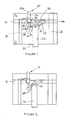
- Figure 1 is a schematic view of a part of a fuel injector for use in delivering fuel to an engine cylinder or other combustion space of an internal combustion engine.
- the fuel injector comprises an injector nozzle (only part of which is shown) and a three-way nozzle control valve (NCV) 10 of one embodiment of the present invention.
- the injector nozzle includes an injector body or injector housing 12.
- the NCV 10 is housed within a valve housing 14 and an intermediate housing, for example a shim plate 16, which is located between the injector body 12 and the valve housing 14.
- the injector nozzle further includes a valve needle which is operable by means of the NCV 10 to control fuel flow into an associated combustion space (not shown) through nozzle outlet openings.
- a lower part of the valve needle is not shown, but terminates in a valve tip which is engageable with a valve needle seat so as to control fuel delivery through the outlet openings into the combustion space.
- a spring may also be provided for biasing the valve needle towards the valve needle seat.
- an upper end 20 of the valve needle remote from the outlet openings is located within a control chamber 18 defined within the injector body 12.
- the upper end of the valve needle may be referred to as the "needle piston" 20, sliding movement of which is guided within a guide bore 22 provided in the injector body 12.
- the needle piston 20 may be integral with the lower part of the valve needle, but alternatively may be a separate part carried by the valve needle.
- a step 24 along the length of the needle piston 20 is defined between the guided portion of the needle piston and a reduced diameter tip 26 at its uppermost end.
- fuel under high pressure is delivered from a first fuel supply passage 28 to a nozzle chamber (not shown) within which the lower part of the valve needle is located. From the nozzle chamber, high pressure fuel is able to flow through the outlet openings of the nozzle when the valve needle is moved away from the valve needle seat.
- the control chamber 18 is located axially in line with and above the needle piston 20 in the orientation shown in Figure 1 .
- the control chamber 18 is defined within the injector body 12 in part by the guide bore 22 and in part by an end surface of the tip 26 of the needle piston 20, and is closed by the lower surface of the shim plate 16.
- Fuel pressure within the control chamber 18 applies a force to the needle piston 20, which serves to urge the needle piston in a downward direction and, hence, serves to urge the valve needle against the valve needle seat to prevent fuel injection through the outlet openings.
- Fuel under high pressure is delivered from a second fuel supply passage 30 to the control chamber 18 via the NCV 10.
- valve needle In use, with high pressure fuel supplied to the nozzle chamber through the supply passage 28, an upwards force is applied to a thrust surface or surfaces (not shown) of the valve needle which serves to urge the valve needle away from the valve needle seat. If fuel pressure within the control chamber 18 is reduced sufficiently, the upwards force acting on the thrust surface due to fuel pressure within the nozzle chamber, in addition to the force from the gas pressure in the combustion chamber acting on the tip of the valve needle, is sufficient to overcome the downwards force acting on the end surface of the needle piston 20, and the force on the valve needle provided by the spring (the spring pre-load force). The valve needle therefore lifts away from the valve needle seat to commence fuel injection through the nozzle outlets.
- the pressure of fuel within the control chamber 18 is controlled by means of the NCV 10.
- the NCV 10 includes a control valve member in the form of a valve pin including an upper portion 32a and a lower portion 32b.
- the upper portion of the valve pin referred to as the guide portion 32a, is slidable within a guide bore 34 defined in the NCV housing 14.
- the lower portion of the valve pin referred to as the valve head 32b, is located and slidable within a chamber 36 defined within the shim plate 16.
- the injector body 12, adjacent to the lower face of the shim plate, is provided with a drain passage 38 which opens into the shim plate chamber 36.
- the drain passage 38 communicates with a low pressure drain 40.
- the shim plate 16 is provided with first and second axial through-drillings, 42, 44 respectively, and a cross slot 46 on its upper face which communicates with the first and second axial drillings 42, 44 at their uppermost ends and connects, at one end, with the shim plate chamber 36.
- the first axial drilling defines a spill passage 42 for fuel flow out of the control chamber the spill passage being provided with an orifice (not shown) which defines the rate of flow of fuel therethrough.
- the upper face of the injector body 12 defines a first valve seat 48 for the head portion 32b of the valve pin of the NCV 10.
- the head portion 32b of the valve pin is engaged with the first valve seat 48 when the valve pin is moved into a first valve position, in which circumstances communication between the shim plate chamber 36 and the drain passage 38 is broken and communication between the shim plate chamber 36 and the second supply passage 30 is open.
- the NCV housing 14 defines, at its lower surface, a second valve seat 50, in the form of a conical valve seat, for the head portion 32b of the valve pin.
- the head portion 32b of the valve pin is engaged with the second valve seat 50 when the valve pin is moved into a second valve position, in which circumstances communication between the second supply passage 30 and the shim plate chamber 36 is broken and communication between the shim plate chamber 36 and the drain passage 38 is open.
- valve pin is biased into engagement with the first valve seat 48 by means of a spring (not shown) or other biasing means. Movement of the valve pin 32a, 32b is controlled by means of an electromagnetic actuator arrangement (not shown), or another suitable actuator such as a piezoelectric actuator or a magnetorestrictive actuator.
- the valve pin 32a, 32b is balanced to high-pressure (i.e. to the pressure of fuel in the second supply passage 30) as the diameter of the head portion 32b of the valve pin at the first valve seat 48 is equal to the diameter of the guide bore 34 for the guide portion 32a of the valve pin.
- valve seats for the valve pin is a conical valve seat (i.e. the second valve seat 50) and the other seat is defined by a flat surface (i.e. the first valve seat 48 defined by the injector housing 12), a manufacturing benefit is achieved compared to a valve design having two conical seats which are more difficult to machine with a sufficiently high degree of concentricity.
- the injector body 12 is provided with a flow passage 52, referred to as a spill passage, which communicates with the control chamber 18 at the upper end of the needle piston 20, intersecting the control chamber 18 at an oblique angle.
- the outer surface of the needle piston 20 is cooperable with an entry port of the spill passage 52, with the position of the needle piston 20 within the guide bore 22 determining the extent to which the entry port is covered and, hence, the extent to which communication between the control chamber 18 and the spill passage 52 is open.
- the second axial drilling 44 in the shim plate 36 opens at the lower face of the shim plate 16 and communicates with the end of the spill passage 52 remote from the entry port.
- the spill passage 42 in the shim plate 16 also opens at the lower face of the shim plate 16 and communicates with the control chamber 18 directly. Therefore, between the shim plate chamber 36 and the control chamber 18 there are two flow routes for fuel: a first route via the spill passage 52 in the injector body 12, the second axial passage 44 in the shim plate 16 and the cross slot 46, and a second route via the spill passage 42 in the shim plate 16 and the cross slot 46.
- the cross slot 46 may be provided in the NCV housing 14 instead of in the shim plate 16, or may be provided in a combination of both the NCV housing 14 and the shim plate 16.
- valve pin 32a, 32b In use, when the NCV 10 is de-actuated, the valve pin 32a, 32b is in its first valve position such that the head portion 32b is in engagement with the first valve seat 48 under the spring force. In this position, fuel at high pressure is able to flow from the second supply passage 30 past the second valve seat 50 and into the shim plate chamber 36, from where it can flow into the control chamber 18 through the first route (via the cross slot 46 and the spill passage 42 in the shim plate 16) and the second route (via the cross slot 46, the second axial passage 44 and the spill passage 52 in the injector body 12).
- control chamber 18 is pressurised and the needle piston 20 is urged downwards, hence the valve needle is urged downwards against the valve needle seat so that injection through the outlet openings does not occur. It will be appreciated that pressurising the control chamber 18 ensures the upwards force acting on the thrust surface of the valve needle, in combination with any force due to combustion chamber pressure acting on the tip of the valve needle, is overcome sufficiently to seat the valve needle against the valve needle seat.
- the rate at which the valve needle is caused to move away from the valve needle seat is determined by the rate of flow of fuel out of the control chamber 18 to the low pressure drain 40.
- the entry port to the spill passage 52 is fully uncovered by the needle piston 20 so that a relatively large flow path exists for fuel flowing out of the control chamber 18 to the low pressure drain 40 via the spill passage 52, the second axial drilling 44 in the shim plate 16, the cross slot 46 and the shim plate chamber 36.
- fuel also flows out of the control chamber 18 through the spill passage 42 in the shim plate 16, the cross slot 46 and the shim plate chamber 36.
- the step 24 along the length of the needle piston 20 moves past the lower edge of the entry port to the spill passage 52 in the injector body 12 so that the entry port becomes partially covered by the needle piston 20.
- the flow of fuel out of the control chamber 18 through the spill passage 52 is more restricted, and so damping of valve needle movement is increased (i.e. movement of the valve needle is more heavily damped during the middle range of movement compared to the initial range of movement).
- the rate of flow of fuel out of the control chamber 18 is restricted still further as the valve needle continues to move through its range of movement and the entry port to the spill passage 52 is closed to an increasingly greater extent. Damping of valve needle movement is therefore most significant towards the end of its range of movement.
- the tip 26 of the needle piston 20 Towards the very end of its range of travel, as the tip 26 of the needle piston 20 approaches the spill passage 42, a further throttling effect occurs, localised at the entry port to the spill passage 42, so that the rate of flow of fuel out of the control chamber 18 is reduced further.
- the tip 26 of the needle piston 20 hits the lift stop 54 so that the spill passage 42 is covered completely.
- the optimum damping profile at the end of lift can be achieved by selecting (i) the relative sizing of the diameter of the tip 26 and the diameter of the remainder of the needle piston 20, (ii) the relative height of the tip 26 and the step 24 and (iii) the shape of the tip 26 (i.e. whether it is tapered or has another profile).
- the spill passage 42 may be offset from axial alignment with the needle piston 20 so that this localised throttling effect at the very end of full lift is avoided altogether.
- the tip 26 of the needle piston 20 Towards the very end of its range of travel, as the tip 26 of the needle piston 20 approaches the spill passage 42, a further throttling effect occurs, localised at the entry port to the spill passage 42, so that the rate of flow of fuel out of the control chamber 18 is reduced further. Eventually the tip 26 of the needle piston 20 hits the lift stop 54 so that the spill passage 42 is covered completely.
- the spill passage 42 may be offset from axial alignment with the needle piston 20 so that this localised throttling effect at full lift is avoided.
- the point at which the entry port to the spill passage 52 in the injector body 12 becomes fully covered may occur after the valve needle has moved only a short way through its full range of movement or may occur as the needle piston 20 approaches the end of its full range of movement, just prior to hitting the upper lift stop 54.
- the remainder of movement of the valve needle is therefore governed solely by the rate of flow of fuel through the spill passage 42 in the shim plate 16.
- the geometry of the valve needle, and the point at which the entry port to the spill passage 52 becomes fully covered are selected so as to give the desired lift characteristics and to ensure that the velocity at which the needle piston 20 approaches the upper lift stop 54 is reduced compared to its initial speed of movement just after valve needle opening.
- the spill passage 52 in the injector body 12 may remain slightly uncovered even as the needle piston 20 approaches the upper lift stop 54 so that there is a parallel flow through both spill passages 42, 52 through the full range of valve needle movement.
- valve needle closing phase that is when the NCV 10 is de-actuated, the head portion 32b of the valve pin is urged against the first valve seat 48 and the second valve seat 50 is open so that fuel flows from the second supply passage 30, past the second valve seat 50 and into the control chamber 18.
- the spill passage 52 in the injector body is fully covered when the needle piston 20 is against its upper lift stop 54, initially fuel flows into the control chamber 18 only through the spill passage 42 in the shim plate 16.
- the entry port to the spill passage 52 in the injector body 12 starts to open, at which point fuel flows into the control chamber 18 through two routes: a first route through the cross slot 46 and the spill passage 42 in the shim plate 16 and a second route through the cross slot 46, the second axial passage 44 in the shim plate 16 and the spill passage 52 in the injector body 12.
- This causes a rapid equalisation of pressure between the control chamber 18 and the nozzle chamber during the closing phase.
- the needle spring then provides the force to close the valve needle against the valve needle seat with rapid movement and, hence, a rapid termination of fuel injection is achieved.
- variable spill passage 52 in the injector body 12 may be removed altogether so that the spill passage 42 in the shim plate 16 is the only flow passage to/from the control chamber 18.
- the rate of movement of the needle piston 20, and hence the valve needle is fixed over its range of movement.
- the spill passage 42 in the shim plate 16 may be removed altogether so that the spill passage 52 in the injector body 12 is the only flow path for fuel out of the control chamber 18 when the NCV 10 is actuated.
- the range of valve needle movement and the overlap between the needle piston 20 and the spill passage 52 must be sized to ensure that the spill passage 52 is still open partially at full lift (i.e. the fully open position) and is not fully covered. This ensures that the spill passage 52 can still provide a refilling capability for the control chamber 18 at the top of needle lift when it is required to re-pressurise the control chamber 18 to close the valve needle.
- the shim plate 16 between the NCV housing 14 and the injector body 12 provides particular advantages from a manufacturing perspective. Firstly, it is beneficial to define the shim plate chamber 36 in a separate part (the shim plate 16), rather than in the NCV housing 14 itself, as the chamber 36 can be manufactured conveniently by boring or drilling through the shim plate 16 from one side to the other. If the NCV housing 14 abuts the injector body 12 directly, it is more difficult to create an equivalent chamber in the lower face of the NCV housing 14, as in existing designs.
- the presence of the shim plate 16 allows the guide bore 34 for the body portion 32a to be located as closely as possible to a grinding spindle support during manufacture: it is considered important for the grinding spindle to approach the guide bore 34 from below (in the orientation shown in Figure 1 ) as it is the lower surface of the NCV housing 14 which has to be especially accurately orientated at right angles to the guide bore 34.
- the grinding spindle can also have a relatively small diameter as the grinding spindle support can be located more closely to the entry to the guide bore 34 for the control valve pin 32a, 32b. With a relatively small diameter grinding spindle it is therefore possible to manufacture a relatively small diameter guide bore 34 for a relatively small diameter control valve pin 32a, 32b.
- the presence of the shim plate 16 enables the second valve seat 50 of the NCV 10 to be located on the lower surface of NCV housing 14, enabling a convenient manufacturing processes and ensuring accurate depth to the second valve seat 50.
- a further benefit is achieved in that the provision of the shim plate 16 enables the lift of the control valve pin 32a, 32b to be set by selecting the appropriate thickness for the shim plate 16, as it is the thickness of the shim plate 16 which determines the separation of the first and second valve seats 48, 50 defined by the injector body 12 and the NCV housing 14, respectively. Furthermore, the head portion 32b of the control valve pin can be kept to a minimum height and the volumes of the shim plate chamber 36 around the valve head 32b (and the other volumes and passages 46, 42, 44 within the shim plate) can easily be kept relatively small. Finally, the shim plate 16 enables some passages to be fabricated in a manner which might otherwise be difficult to manufacture or create stress raisers.
- the present invention may be implemented in a common rail injector, in which a common supply (rail) delivers fuel to at least two injectors of the engine, or may be implemented in an electronic unit injector (EUI) in which each injector of the engine is provided with its own dedicated pump, and hence high pressure fuel supply, within the same unit as the injector, or within an Electronic Unit Pump (EUP) in which each injector of the engine is provided with its own dedicated pump, and hence high pressure fuel supply, but separated from the associated injector via pipework.
- EUI electronic unit injector
- EUP Electronic Unit Pump
- the invention may also be implemented in a hybrid scheme, having dual common rail/EUI functionality.
Landscapes
- Engineering & Computer Science (AREA)
- Chemical & Material Sciences (AREA)
- Combustion & Propulsion (AREA)
- Mechanical Engineering (AREA)
- General Engineering & Computer Science (AREA)
- Physics & Mathematics (AREA)
- Fluid Mechanics (AREA)
- Fuel-Injection Apparatus (AREA)
Claims (13)
- Injecteur de carburant comprenant un pointeau de valve (20) pour commander l'injection de carburant via une sortie d'injecteur, une chambre de commande (18) pour recevoir du carburant et une valve de commande à trois voies qui commande la pression du carburant dans la chambre de commande (18) afin de commander le mouvement d'ouverture et de fermeture du pointeau de valve pour commander l'injection du carburant via la sortie, dans lequel la valve de commande à trois voies commande la communication entre (a) un premier passage (38) et un second passage (36) et (b) un troisième passage (30) et le second passage (36), la valve de commande comprenant :un premier boîtier (14) doté d'un perçage guide (34) pour un élément de valve de commande (32a, 32b), grâce à quoi le mouvement de l'élément de valve de commande (32a, 32b) est guidé à l'intérieur du perçage guide (34),un premier siège de valve (48), défini par un second boîtier (12), avec lequel une portion de tête (32b) de l'élément de valve de commande peut venir s'engager pour commander la communication entre le premier et le second passage (3 8, 3 6),un second siège de valve (50) défini par le premier boîtier (14), avec lequel l'élément de valve de commande peut venir s'engager pour commander la communication entre le second et le troisième passage d'écoulement (36, 30), etun boîtier intermédiaire (16) situé entre le premier et le second boîtier (14, 12), dans lequel le second passage (36) est défini dans le boîtier intermédiaire (16), et dans lequel le boîtier intermédiaire (16) définit un arrêt de levée (54) pour le pointeau de valve ou pour une partie (20) portée par le pointeau de valve.
- Injecteur de carburant selon la revendication 1, dans lequel l'élément de valve de commande inclut une portion guide (32a) qui est guidée dans le perçage guide (34) et une tête de valve (32b) qui peut venir s'engager contre le premier et le second siège de valve (48, 50) pour commander la communication entre le premier passage (38) et le second passage (36) et entre le second passage (36) et le troisième passage (30) respectivement.
- Injecteur de carburant selon la revendication 2, dans lequel l'un au moins du premier et du second siège de valve est défini par une surface plane du boîtier concerné (12, 14).
- Injecteur de carburant selon l'une quelconque des revendications 1 à 3, dans lequel la chambre de commande (18) communique avec le second passage (36) de la valve de commande à trois voies.
- Injecteur de carburant selon la revendication 4, comprenant en outre un passage de déversement (42) entre la chambre de commande (18) et le second passage (36) qui présente une restriction fixe vis-à-vis de l'écoulement du carburant sortant de la chambre de commande (18) quand l'élément de valve de commande est déplacé en éloignement du premier siège de valve (48).
- Injecteur de carburant selon la revendication 5, dans lequel le passage de déversement (42) est prévu dans le boîtier intermédiaire (16).
- Injecteur de carburant selon la revendication 5 ou 6, dans lequel le boîtier intermédiaire (16) comprend en outre une fente en croix (46) sur sa surface pour connecter le passage de déversement (42) et le second passage (36).
- Injecteur de carburant selon l'une quelconque des revendications 1 à 7, dans lequel le premier passage (38) communique avec un drain à basse pression (40) et le troisième passage (30) communique avec une source de carburant à haute pression.
- Injecteur de carburant selon la revendication 8, dans lequel l'élément de valve de commande est équilibré en pression vis-à-vis de la pression du carburant dans le troisième passage (30) lorsqu'il est en assise contre le premier siège de valve (48).
- Injecteur de carburant selon l'une quelconque des revendications 1 à 9, dans lequel le premier boîtier (14) est un boîtier de valve de commande et le second boîtier (12) est un boîtier d'injecteur, le boîtier d'injecteur (12) étant doté d'un perçage guide (22) pour le pointeau de valve ou pour une partie (20) portée par le pointeau de valve.
- Injecteur de carburant selon l'une quelconque des revendications 1 à 10, comprenant en outre un passage de déversement additionnel (52) entre la chambre de commande (18) et le second passage (36) qui présente une restriction variable vis-à-vis de l'écoulement de carburant hors de la chambre de commande (18) quand l'élément de valve de commande est déplacé en éloignement du premier siège de valve (48).
- Injecteur de carburant selon la revendication 11, dans lequel le boîtier intermédiaire comprend encore une fente en croix sur sa surface pour connecter le passage de déversement additionnel (52) et le second passage.
- Injecteur de carburant selon la revendication 11 ou 12, dans lequel le pointeau de valve, ou une partie (20) portée par le pointeau de valve, coopère avec le passage de déversement additionnel (52) pour assurer une restriction variable vis-à-vis de l'écoulement de carburant hors de la chambre de commande, en fonction de l'étendue du mouvement d'ouverture du pointeau de valve.
Priority Applications (9)
| Application Number | Priority Date | Filing Date | Title |
|---|---|---|---|
| EP09168747A EP2290219B1 (fr) | 2009-08-26 | 2009-08-26 | Vanne à trois voies |
| EP10171128A EP2290220B1 (fr) | 2009-08-26 | 2010-07-28 | Injecteur de carburant avec vanne à trois voies |
| AT10171128T ATE549503T1 (de) | 2009-08-26 | 2010-07-28 | Kraftstoffinjektor mit dreiwege-steuerventil |
| JP2010184364A JP5118732B2 (ja) | 2009-08-26 | 2010-08-19 | 燃料インジェクタ |
| KR1020100080797A KR101224409B1 (ko) | 2009-08-26 | 2010-08-20 | 연료 인젝터 |
| US12/861,043 US9157400B2 (en) | 2009-08-26 | 2010-08-23 | Fuel injector |
| BRPI1003254A BRPI1003254A8 (pt) | 2009-08-26 | 2010-08-23 | Injetor de combustível |
| RU2010135597/06A RU2459107C2 (ru) | 2009-08-26 | 2010-08-25 | Топливный инжектор (варианты) |
| CN2010102650059A CN102003552B (zh) | 2009-08-26 | 2010-08-26 | 燃料喷射器 |
Applications Claiming Priority (1)
| Application Number | Priority Date | Filing Date | Title |
|---|---|---|---|
| EP09168747A EP2290219B1 (fr) | 2009-08-26 | 2009-08-26 | Vanne à trois voies |
Publications (2)
| Publication Number | Publication Date |
|---|---|
| EP2290219A1 EP2290219A1 (fr) | 2011-03-02 |
| EP2290219B1 true EP2290219B1 (fr) | 2013-01-23 |
Family
ID=41479238
Family Applications (2)
| Application Number | Title | Priority Date | Filing Date |
|---|---|---|---|
| EP09168747A Active EP2290219B1 (fr) | 2009-08-26 | 2009-08-26 | Vanne à trois voies |
| EP10171128A Active EP2290220B1 (fr) | 2009-08-26 | 2010-07-28 | Injecteur de carburant avec vanne à trois voies |
Family Applications After (1)
| Application Number | Title | Priority Date | Filing Date |
|---|---|---|---|
| EP10171128A Active EP2290220B1 (fr) | 2009-08-26 | 2010-07-28 | Injecteur de carburant avec vanne à trois voies |
Country Status (8)
| Country | Link |
|---|---|
| US (1) | US9157400B2 (fr) |
| EP (2) | EP2290219B1 (fr) |
| JP (1) | JP5118732B2 (fr) |
| KR (1) | KR101224409B1 (fr) |
| CN (1) | CN102003552B (fr) |
| AT (1) | ATE549503T1 (fr) |
| BR (1) | BRPI1003254A8 (fr) |
| RU (1) | RU2459107C2 (fr) |
Cited By (1)
| Publication number | Priority date | Publication date | Assignee | Title |
|---|---|---|---|---|
| US10294908B2 (en) | 2013-05-21 | 2019-05-21 | Westport Power Inc. | Fuel injector |
Families Citing this family (7)
| Publication number | Priority date | Publication date | Assignee | Title |
|---|---|---|---|---|
| ATE546636T1 (de) * | 2009-08-26 | 2012-03-15 | Delphi Tech Holding Sarl | Kraftstoffeinspritzdüse |
| EP2527637B1 (fr) | 2011-05-23 | 2014-10-08 | Continental Automotive GmbH | Injecteur pour injection de fluides |
| EP2669503A1 (fr) * | 2012-05-29 | 2013-12-04 | Delphi Technologies Holding S.à.r.l. | Injecteur de carburant |
| US10982635B2 (en) | 2012-05-29 | 2021-04-20 | Delphi Technologies Ip Limited | Fuel injector and method for controlling the same |
| EP3180510B1 (fr) * | 2014-08-15 | 2018-10-17 | Wärtsilä Finland Oy | Agencement de soupape d'injection de carburant pour moteur à combustion interne |
| RU2646170C2 (ru) * | 2016-07-06 | 2018-03-01 | федеральное государственное бюджетное образовательное учреждение высшего образования "Московский государственный технический университет имени Н.Э. Баумана (национальный исследовательский университет)" (МГТУ им. Н.Э. Баумана) | Электрогидравлическая форсунка аккумуляторной топливной системы дизельного двигателя |
| CN108506130B (zh) * | 2018-04-18 | 2024-06-11 | 莆田市博泰动力设备有限公司 | 减少高压共轨燃油动态泄漏的喷油器 |
Family Cites Families (12)
| Publication number | Priority date | Publication date | Assignee | Title |
|---|---|---|---|---|
| SU798340A2 (ru) * | 1974-06-04 | 1981-01-23 | Коломенский Филиал Всесоюзногозаочного Политехнического Института | Форсунка с гидравлическим запира-НиЕМ иглы |
| JP3846917B2 (ja) * | 1995-07-13 | 2006-11-15 | 株式会社デンソー | 燃料噴射装置 |
| EP1163440B1 (fr) * | 1999-03-18 | 2005-10-05 | Delphi Technologies, Inc. | Injecteur de carburant |
| DE10024702A1 (de) * | 2000-05-18 | 2001-11-22 | Bosch Gmbh Robert | Einspritzanordnung für ein Kraftstoff-Speichereinspritzsystem einer Verbrennungsmaschine |
| US6354270B1 (en) * | 2000-06-29 | 2002-03-12 | Caterpillar Inc. | Hydraulically actuated fuel injector including a pilot operated spool valve assembly and hydraulic system using same |
| US6725838B2 (en) * | 2001-10-09 | 2004-04-27 | Caterpillar Inc | Fuel injector having dual mode capabilities and engine using same |
| US6776190B2 (en) * | 2002-04-08 | 2004-08-17 | Caterpillar Inc. | Valve lift spacer and valve using same |
| EP1613856B1 (fr) * | 2003-04-02 | 2008-07-09 | Robert Bosch Gmbh | Injecteur de carburant comportant un transmetteur de pression commande par une soupape asservie |
| DE10325620A1 (de) | 2003-04-02 | 2004-10-14 | Robert Bosch Gmbh | Servoventilangesteuerter Kraftstoffinjektor mit Druckübersetzer |
| US6955114B2 (en) * | 2003-12-05 | 2005-10-18 | Caterpillar Inc | Three way valve and electro-hydraulic actuator using same |
| DE102005032464A1 (de) * | 2005-07-12 | 2007-01-25 | Robert Bosch Gmbh | Kraftstoffinjektor mit Vorsteuerraum |
| JP4297181B2 (ja) * | 2007-07-17 | 2009-07-15 | 株式会社デンソー | インジェクタ |
-
2009
- 2009-08-26 EP EP09168747A patent/EP2290219B1/fr active Active
-
2010
- 2010-07-28 AT AT10171128T patent/ATE549503T1/de active
- 2010-07-28 EP EP10171128A patent/EP2290220B1/fr active Active
- 2010-08-19 JP JP2010184364A patent/JP5118732B2/ja active Active
- 2010-08-20 KR KR1020100080797A patent/KR101224409B1/ko active IP Right Grant
- 2010-08-23 BR BRPI1003254A patent/BRPI1003254A8/pt not_active Application Discontinuation
- 2010-08-23 US US12/861,043 patent/US9157400B2/en active Active
- 2010-08-25 RU RU2010135597/06A patent/RU2459107C2/ru active
- 2010-08-26 CN CN2010102650059A patent/CN102003552B/zh active Active
Cited By (1)
| Publication number | Priority date | Publication date | Assignee | Title |
|---|---|---|---|---|
| US10294908B2 (en) | 2013-05-21 | 2019-05-21 | Westport Power Inc. | Fuel injector |
Also Published As
| Publication number | Publication date |
|---|---|
| KR101224409B1 (ko) | 2013-01-22 |
| US9157400B2 (en) | 2015-10-13 |
| EP2290220A1 (fr) | 2011-03-02 |
| KR20110021663A (ko) | 2011-03-04 |
| RU2459107C2 (ru) | 2012-08-20 |
| CN102003552A (zh) | 2011-04-06 |
| BRPI1003254A8 (pt) | 2017-08-15 |
| JP2011047400A (ja) | 2011-03-10 |
| JP5118732B2 (ja) | 2013-01-16 |
| EP2290220B1 (fr) | 2012-03-14 |
| CN102003552B (zh) | 2013-09-04 |
| EP2290219A1 (fr) | 2011-03-02 |
| US20110049272A1 (en) | 2011-03-03 |
| BRPI1003254A2 (pt) | 2012-12-25 |
| RU2010135597A (ru) | 2012-02-27 |
| ATE549503T1 (de) | 2012-03-15 |
Similar Documents
| Publication | Publication Date | Title |
|---|---|---|
| EP2295784B1 (fr) | Injecteur à carburant | |
| EP2290219B1 (fr) | Vanne à trois voies | |
| US9234487B2 (en) | Injection nozzle | |
| EP2669503A1 (fr) | Injecteur de carburant | |
| US20110180634A1 (en) | Nozzle body, nozzle assembly and fuel injector, and method for producing a nozzle body | |
| US7568634B2 (en) | Injection nozzle | |
| US10982635B2 (en) | Fuel injector and method for controlling the same | |
| EP2615294A1 (fr) | Injecteur à carburant | |
| US7309030B2 (en) | Injection nozzle | |
| US20040069274A1 (en) | 3/2 Directional control valve | |
| EP3399177B1 (fr) | Injecteur de carburant | |
| EP3230577B1 (fr) | Injecteur de carburant | |
| EP1717435B1 (fr) | Buse d'injection |
Legal Events
| Date | Code | Title | Description |
|---|---|---|---|
| PUAI | Public reference made under article 153(3) epc to a published international application that has entered the european phase |
Free format text: ORIGINAL CODE: 0009012 |
|
| AK | Designated contracting states |
Kind code of ref document: A1 Designated state(s): AT BE BG CH CY CZ DE DK EE ES FI FR GB GR HR HU IE IS IT LI LT LU LV MC MK MT NL NO PL PT RO SE SI SK SM TR |
|
| AX | Request for extension of the european patent |
Extension state: AL BA RS |
|
| 17P | Request for examination filed |
Effective date: 20110902 |
|
| GRAP | Despatch of communication of intention to grant a patent |
Free format text: ORIGINAL CODE: EPIDOSNIGR1 |
|
| GRAS | Grant fee paid |
Free format text: ORIGINAL CODE: EPIDOSNIGR3 |
|
| GRAA | (expected) grant |
Free format text: ORIGINAL CODE: 0009210 |
|
| AK | Designated contracting states |
Kind code of ref document: B1 Designated state(s): AT BE BG CH CY CZ DE DK EE ES FI FR GB GR HR HU IE IS IT LI LT LU LV MC MK MT NL NO PL PT RO SE SI SK SM TR |
|
| AX | Request for extension of the european patent |
Extension state: AL BA RS |
|
| REG | Reference to a national code |
Ref country code: GB Ref legal event code: FG4D |
|
| REG | Reference to a national code |
Ref country code: CH Ref legal event code: EP |
|
| REG | Reference to a national code |
Ref country code: AT Ref legal event code: REF Ref document number: 595110 Country of ref document: AT Kind code of ref document: T Effective date: 20130215 Ref country code: CH Ref legal event code: EP |
|
| REG | Reference to a national code |
Ref country code: IE Ref legal event code: FG4D |
|
| REG | Reference to a national code |
Ref country code: DE Ref legal event code: R096 Ref document number: 602009012951 Country of ref document: DE Effective date: 20130321 |
|
| REG | Reference to a national code |
Ref country code: AT Ref legal event code: MK05 Ref document number: 595110 Country of ref document: AT Kind code of ref document: T Effective date: 20130123 |
|
| REG | Reference to a national code |
Ref country code: LT Ref legal event code: MG4D |
|
| REG | Reference to a national code |
Ref country code: NL Ref legal event code: VDEP Effective date: 20130123 |
|
| PG25 | Lapsed in a contracting state [announced via postgrant information from national office to epo] |
Ref country code: ES Free format text: LAPSE BECAUSE OF FAILURE TO SUBMIT A TRANSLATION OF THE DESCRIPTION OR TO PAY THE FEE WITHIN THE PRESCRIBED TIME-LIMIT Effective date: 20130504 Ref country code: IS Free format text: LAPSE BECAUSE OF FAILURE TO SUBMIT A TRANSLATION OF THE DESCRIPTION OR TO PAY THE FEE WITHIN THE PRESCRIBED TIME-LIMIT Effective date: 20130523 Ref country code: NO Free format text: LAPSE BECAUSE OF FAILURE TO SUBMIT A TRANSLATION OF THE DESCRIPTION OR TO PAY THE FEE WITHIN THE PRESCRIBED TIME-LIMIT Effective date: 20130423 Ref country code: LT Free format text: LAPSE BECAUSE OF FAILURE TO SUBMIT A TRANSLATION OF THE DESCRIPTION OR TO PAY THE FEE WITHIN THE PRESCRIBED TIME-LIMIT Effective date: 20130123 Ref country code: BE Free format text: LAPSE BECAUSE OF FAILURE TO SUBMIT A TRANSLATION OF THE DESCRIPTION OR TO PAY THE FEE WITHIN THE PRESCRIBED TIME-LIMIT Effective date: 20130123 Ref country code: AT Free format text: LAPSE BECAUSE OF FAILURE TO SUBMIT A TRANSLATION OF THE DESCRIPTION OR TO PAY THE FEE WITHIN THE PRESCRIBED TIME-LIMIT Effective date: 20130123 Ref country code: BG Free format text: LAPSE BECAUSE OF FAILURE TO SUBMIT A TRANSLATION OF THE DESCRIPTION OR TO PAY THE FEE WITHIN THE PRESCRIBED TIME-LIMIT Effective date: 20130423 Ref country code: SE Free format text: LAPSE BECAUSE OF FAILURE TO SUBMIT A TRANSLATION OF THE DESCRIPTION OR TO PAY THE FEE WITHIN THE PRESCRIBED TIME-LIMIT Effective date: 20130123 |
|
| PG25 | Lapsed in a contracting state [announced via postgrant information from national office to epo] |
Ref country code: NL Free format text: LAPSE BECAUSE OF FAILURE TO SUBMIT A TRANSLATION OF THE DESCRIPTION OR TO PAY THE FEE WITHIN THE PRESCRIBED TIME-LIMIT Effective date: 20130123 Ref country code: PT Free format text: LAPSE BECAUSE OF FAILURE TO SUBMIT A TRANSLATION OF THE DESCRIPTION OR TO PAY THE FEE WITHIN THE PRESCRIBED TIME-LIMIT Effective date: 20130523 Ref country code: GR Free format text: LAPSE BECAUSE OF FAILURE TO SUBMIT A TRANSLATION OF THE DESCRIPTION OR TO PAY THE FEE WITHIN THE PRESCRIBED TIME-LIMIT Effective date: 20130424 Ref country code: FI Free format text: LAPSE BECAUSE OF FAILURE TO SUBMIT A TRANSLATION OF THE DESCRIPTION OR TO PAY THE FEE WITHIN THE PRESCRIBED TIME-LIMIT Effective date: 20130123 Ref country code: PL Free format text: LAPSE BECAUSE OF FAILURE TO SUBMIT A TRANSLATION OF THE DESCRIPTION OR TO PAY THE FEE WITHIN THE PRESCRIBED TIME-LIMIT Effective date: 20130123 Ref country code: LV Free format text: LAPSE BECAUSE OF FAILURE TO SUBMIT A TRANSLATION OF THE DESCRIPTION OR TO PAY THE FEE WITHIN THE PRESCRIBED TIME-LIMIT Effective date: 20130123 Ref country code: SI Free format text: LAPSE BECAUSE OF FAILURE TO SUBMIT A TRANSLATION OF THE DESCRIPTION OR TO PAY THE FEE WITHIN THE PRESCRIBED TIME-LIMIT Effective date: 20130123 |
|
| PG25 | Lapsed in a contracting state [announced via postgrant information from national office to epo] |
Ref country code: HR Free format text: LAPSE BECAUSE OF FAILURE TO SUBMIT A TRANSLATION OF THE DESCRIPTION OR TO PAY THE FEE WITHIN THE PRESCRIBED TIME-LIMIT Effective date: 20130123 |
|
| PG25 | Lapsed in a contracting state [announced via postgrant information from national office to epo] |
Ref country code: SK Free format text: LAPSE BECAUSE OF FAILURE TO SUBMIT A TRANSLATION OF THE DESCRIPTION OR TO PAY THE FEE WITHIN THE PRESCRIBED TIME-LIMIT Effective date: 20130123 Ref country code: DK Free format text: LAPSE BECAUSE OF FAILURE TO SUBMIT A TRANSLATION OF THE DESCRIPTION OR TO PAY THE FEE WITHIN THE PRESCRIBED TIME-LIMIT Effective date: 20130123 Ref country code: EE Free format text: LAPSE BECAUSE OF FAILURE TO SUBMIT A TRANSLATION OF THE DESCRIPTION OR TO PAY THE FEE WITHIN THE PRESCRIBED TIME-LIMIT Effective date: 20130123 Ref country code: RO Free format text: LAPSE BECAUSE OF FAILURE TO SUBMIT A TRANSLATION OF THE DESCRIPTION OR TO PAY THE FEE WITHIN THE PRESCRIBED TIME-LIMIT Effective date: 20130123 Ref country code: CZ Free format text: LAPSE BECAUSE OF FAILURE TO SUBMIT A TRANSLATION OF THE DESCRIPTION OR TO PAY THE FEE WITHIN THE PRESCRIBED TIME-LIMIT Effective date: 20130123 |
|
| PG25 | Lapsed in a contracting state [announced via postgrant information from national office to epo] |
Ref country code: CY Free format text: LAPSE BECAUSE OF FAILURE TO SUBMIT A TRANSLATION OF THE DESCRIPTION OR TO PAY THE FEE WITHIN THE PRESCRIBED TIME-LIMIT Effective date: 20130123 |
|
| PLBE | No opposition filed within time limit |
Free format text: ORIGINAL CODE: 0009261 |
|
| STAA | Information on the status of an ep patent application or granted ep patent |
Free format text: STATUS: NO OPPOSITION FILED WITHIN TIME LIMIT |
|
| PG25 | Lapsed in a contracting state [announced via postgrant information from national office to epo] |
Ref country code: IT Free format text: LAPSE BECAUSE OF FAILURE TO SUBMIT A TRANSLATION OF THE DESCRIPTION OR TO PAY THE FEE WITHIN THE PRESCRIBED TIME-LIMIT Effective date: 20130123 |
|
| 26N | No opposition filed |
Effective date: 20131024 |
|
| REG | Reference to a national code |
Ref country code: DE Ref legal event code: R097 Ref document number: 602009012951 Country of ref document: DE Effective date: 20131024 |
|
| REG | Reference to a national code |
Ref country code: CH Ref legal event code: PL |
|
| GBPC | Gb: european patent ceased through non-payment of renewal fee |
Effective date: 20130826 |
|
| PG25 | Lapsed in a contracting state [announced via postgrant information from national office to epo] |
Ref country code: MC Free format text: LAPSE BECAUSE OF FAILURE TO SUBMIT A TRANSLATION OF THE DESCRIPTION OR TO PAY THE FEE WITHIN THE PRESCRIBED TIME-LIMIT Effective date: 20130123 Ref country code: LI Free format text: LAPSE BECAUSE OF NON-PAYMENT OF DUE FEES Effective date: 20130831 Ref country code: CH Free format text: LAPSE BECAUSE OF NON-PAYMENT OF DUE FEES Effective date: 20130831 |
|
| REG | Reference to a national code |
Ref country code: IE Ref legal event code: MM4A |
|
| REG | Reference to a national code |
Ref country code: FR Ref legal event code: TP Owner name: DELPHI INTERNATIONAL OPERATIONS LUXEMBOURG S.A, LU Effective date: 20140516 |
|
| PG25 | Lapsed in a contracting state [announced via postgrant information from national office to epo] |
Ref country code: IE Free format text: LAPSE BECAUSE OF NON-PAYMENT OF DUE FEES Effective date: 20130826 Ref country code: GB Free format text: LAPSE BECAUSE OF NON-PAYMENT OF DUE FEES Effective date: 20130826 |
|
| REG | Reference to a national code |
Ref country code: DE Ref legal event code: R081 Ref document number: 602009012951 Country of ref document: DE Owner name: DELPHI INTERNATIONAL OPERATIONS LUXEMBOURG S.A, LU Free format text: FORMER OWNER: DELPHI TECHNOLOGIES HOLDING S.A.R.L., BASCHARAGE, LU Effective date: 20140715 |
|
| PG25 | Lapsed in a contracting state [announced via postgrant information from national office to epo] |
Ref country code: SM Free format text: LAPSE BECAUSE OF FAILURE TO SUBMIT A TRANSLATION OF THE DESCRIPTION OR TO PAY THE FEE WITHIN THE PRESCRIBED TIME-LIMIT Effective date: 20130123 |
|
| PG25 | Lapsed in a contracting state [announced via postgrant information from national office to epo] |
Ref country code: MT Free format text: LAPSE BECAUSE OF FAILURE TO SUBMIT A TRANSLATION OF THE DESCRIPTION OR TO PAY THE FEE WITHIN THE PRESCRIBED TIME-LIMIT Effective date: 20130123 Ref country code: TR Free format text: LAPSE BECAUSE OF FAILURE TO SUBMIT A TRANSLATION OF THE DESCRIPTION OR TO PAY THE FEE WITHIN THE PRESCRIBED TIME-LIMIT Effective date: 20130123 |
|
| PG25 | Lapsed in a contracting state [announced via postgrant information from national office to epo] |
Ref country code: MK Free format text: LAPSE BECAUSE OF FAILURE TO SUBMIT A TRANSLATION OF THE DESCRIPTION OR TO PAY THE FEE WITHIN THE PRESCRIBED TIME-LIMIT Effective date: 20130123 Ref country code: HU Free format text: LAPSE BECAUSE OF FAILURE TO SUBMIT A TRANSLATION OF THE DESCRIPTION OR TO PAY THE FEE WITHIN THE PRESCRIBED TIME-LIMIT; INVALID AB INITIO Effective date: 20090826 Ref country code: LU Free format text: LAPSE BECAUSE OF NON-PAYMENT OF DUE FEES Effective date: 20130826 |
|
| REG | Reference to a national code |
Ref country code: FR Ref legal event code: PLFP Year of fee payment: 7 |
|
| REG | Reference to a national code |
Ref country code: FR Ref legal event code: PLFP Year of fee payment: 8 |
|
| REG | Reference to a national code |
Ref country code: FR Ref legal event code: PLFP Year of fee payment: 9 |
|
| REG | Reference to a national code |
Ref country code: FR Ref legal event code: PLFP Year of fee payment: 10 |
|
| REG | Reference to a national code |
Ref country code: DE Ref legal event code: R081 Ref document number: 602009012951 Country of ref document: DE Owner name: DELPHI TECHNOLOGIES IP LIMITED, BB Free format text: FORMER OWNER: DELPHI INTERNATIONAL OPERATIONS LUXEMBOURG S.A R.L., BASCHARAGE, LU |
|
| P01 | Opt-out of the competence of the unified patent court (upc) registered |
Effective date: 20230327 |
|
| REG | Reference to a national code |
Ref country code: DE Ref legal event code: R081 Ref document number: 602009012951 Country of ref document: DE Owner name: PHINIA DELPHI LUXEMBOURG SARL, LU Free format text: FORMER OWNER: DELPHI TECHNOLOGIES IP LIMITED, ST. MICHAEL, BB |
|
| PGFP | Annual fee paid to national office [announced via postgrant information from national office to epo] |
Ref country code: DE Payment date: 20240709 Year of fee payment: 16 |
|
| PGFP | Annual fee paid to national office [announced via postgrant information from national office to epo] |
Ref country code: FR Payment date: 20240710 Year of fee payment: 16 |