EP2290217B1 - Brennstoffversorgungseinheit - Google Patents
Brennstoffversorgungseinheit Download PDFInfo
- Publication number
- EP2290217B1 EP2290217B1 EP10189356.8A EP10189356A EP2290217B1 EP 2290217 B1 EP2290217 B1 EP 2290217B1 EP 10189356 A EP10189356 A EP 10189356A EP 2290217 B1 EP2290217 B1 EP 2290217B1
- Authority
- EP
- European Patent Office
- Prior art keywords
- throttle
- position sensor
- fuel supply
- magnetic flux
- valve
- Prior art date
- Legal status (The legal status is an assumption and is not a legal conclusion. Google has not performed a legal analysis and makes no representation as to the accuracy of the status listed.)
- Active
Links
Images


Classifications
-
- F—MECHANICAL ENGINEERING; LIGHTING; HEATING; WEAPONS; BLASTING
- F02—COMBUSTION ENGINES; HOT-GAS OR COMBUSTION-PRODUCT ENGINE PLANTS
- F02D—CONTROLLING COMBUSTION ENGINES
- F02D37/00—Non-electrical conjoint control of two or more functions of engines, not otherwise provided for
- F02D37/02—Non-electrical conjoint control of two or more functions of engines, not otherwise provided for one of the functions being ignition
-
- F—MECHANICAL ENGINEERING; LIGHTING; HEATING; WEAPONS; BLASTING
- F02—COMBUSTION ENGINES; HOT-GAS OR COMBUSTION-PRODUCT ENGINE PLANTS
- F02D—CONTROLLING COMBUSTION ENGINES
- F02D11/00—Arrangements for, or adaptations to, non-automatic engine control initiation means, e.g. operator initiated
- F02D11/06—Arrangements for, or adaptations to, non-automatic engine control initiation means, e.g. operator initiated characterised by non-mechanical control linkages, e.g. fluid control linkages or by control linkages with power drive or assistance
- F02D11/10—Arrangements for, or adaptations to, non-automatic engine control initiation means, e.g. operator initiated characterised by non-mechanical control linkages, e.g. fluid control linkages or by control linkages with power drive or assistance of the electric type
- F02D11/106—Detection of demand or actuation
-
- F—MECHANICAL ENGINEERING; LIGHTING; HEATING; WEAPONS; BLASTING
- F02—COMBUSTION ENGINES; HOT-GAS OR COMBUSTION-PRODUCT ENGINE PLANTS
- F02D—CONTROLLING COMBUSTION ENGINES
- F02D35/00—Controlling engines, dependent on conditions exterior or interior to engines, not otherwise provided for
- F02D35/0015—Controlling engines, dependent on conditions exterior or interior to engines, not otherwise provided for using exhaust gas sensors
- F02D35/0046—Controlling fuel supply
- F02D35/0053—Controlling fuel supply by means of a carburettor
-
- F—MECHANICAL ENGINEERING; LIGHTING; HEATING; WEAPONS; BLASTING
- F02—COMBUSTION ENGINES; HOT-GAS OR COMBUSTION-PRODUCT ENGINE PLANTS
- F02D—CONTROLLING COMBUSTION ENGINES
- F02D9/00—Controlling engines by throttling air or fuel-and-air induction conduits or exhaust conduits
- F02D9/08—Throttle valves specially adapted therefor; Arrangements of such valves in conduits
- F02D9/10—Throttle valves specially adapted therefor; Arrangements of such valves in conduits having pivotally-mounted flaps
- F02D9/1035—Details of the valve housing
- F02D9/105—Details of the valve housing having a throttle position sensor
-
- F—MECHANICAL ENGINEERING; LIGHTING; HEATING; WEAPONS; BLASTING
- F02—COMBUSTION ENGINES; HOT-GAS OR COMBUSTION-PRODUCT ENGINE PLANTS
- F02D—CONTROLLING COMBUSTION ENGINES
- F02D9/00—Controlling engines by throttling air or fuel-and-air induction conduits or exhaust conduits
- F02D9/08—Throttle valves specially adapted therefor; Arrangements of such valves in conduits
- F02D9/10—Throttle valves specially adapted therefor; Arrangements of such valves in conduits having pivotally-mounted flaps
- F02D9/1035—Details of the valve housing
- F02D9/1055—Details of the valve housing having a fluid by-pass
-
- F—MECHANICAL ENGINEERING; LIGHTING; HEATING; WEAPONS; BLASTING
- F02—COMBUSTION ENGINES; HOT-GAS OR COMBUSTION-PRODUCT ENGINE PLANTS
- F02M—SUPPLYING COMBUSTION ENGINES IN GENERAL WITH COMBUSTIBLE MIXTURES OR CONSTITUENTS THEREOF
- F02M17/00—Carburettors having pertinent characteristics not provided for in, or of interest apart from, the apparatus of preceding main groups F02M1/00 - F02M15/00
- F02M17/10—Carburettors having one or more fuel passages opening in valve-member of air throttle
- F02M17/12—Carburettors having one or more fuel passages opening in valve-member of air throttle the valve member being of butterfly type
-
- F—MECHANICAL ENGINEERING; LIGHTING; HEATING; WEAPONS; BLASTING
- F16—ENGINEERING ELEMENTS AND UNITS; GENERAL MEASURES FOR PRODUCING AND MAINTAINING EFFECTIVE FUNCTIONING OF MACHINES OR INSTALLATIONS; THERMAL INSULATION IN GENERAL
- F16K—VALVES; TAPS; COCKS; ACTUATING-FLOATS; DEVICES FOR VENTING OR AERATING
- F16K31/00—Actuating devices; Operating means; Releasing devices
- F16K31/02—Actuating devices; Operating means; Releasing devices electric; magnetic
- F16K31/06—Actuating devices; Operating means; Releasing devices electric; magnetic using a magnet, e.g. diaphragm valves, cutting off by means of a liquid
- F16K31/08—Actuating devices; Operating means; Releasing devices electric; magnetic using a magnet, e.g. diaphragm valves, cutting off by means of a liquid using a permanent magnet
- F16K31/082—Actuating devices; Operating means; Releasing devices electric; magnetic using a magnet, e.g. diaphragm valves, cutting off by means of a liquid using a permanent magnet using a electromagnet and a permanent magnet
-
- F—MECHANICAL ENGINEERING; LIGHTING; HEATING; WEAPONS; BLASTING
- F16—ENGINEERING ELEMENTS AND UNITS; GENERAL MEASURES FOR PRODUCING AND MAINTAINING EFFECTIVE FUNCTIONING OF MACHINES OR INSTALLATIONS; THERMAL INSULATION IN GENERAL
- F16K—VALVES; TAPS; COCKS; ACTUATING-FLOATS; DEVICES FOR VENTING OR AERATING
- F16K37/00—Special means in or on valves or other cut-off apparatus for indicating or recording operation thereof, or for enabling an alarm to be given
- F16K37/0025—Electrical or magnetic means
- F16K37/0033—Electrical or magnetic means using a permanent magnet, e.g. in combination with a reed relays
-
- F—MECHANICAL ENGINEERING; LIGHTING; HEATING; WEAPONS; BLASTING
- F16—ENGINEERING ELEMENTS AND UNITS; GENERAL MEASURES FOR PRODUCING AND MAINTAINING EFFECTIVE FUNCTIONING OF MACHINES OR INSTALLATIONS; THERMAL INSULATION IN GENERAL
- F16K—VALVES; TAPS; COCKS; ACTUATING-FLOATS; DEVICES FOR VENTING OR AERATING
- F16K37/00—Special means in or on valves or other cut-off apparatus for indicating or recording operation thereof, or for enabling an alarm to be given
- F16K37/0025—Electrical or magnetic means
- F16K37/0041—Electrical or magnetic means for measuring valve parameters
-
- G—PHYSICS
- G01—MEASURING; TESTING
- G01D—MEASURING NOT SPECIALLY ADAPTED FOR A SPECIFIC VARIABLE; ARRANGEMENTS FOR MEASURING TWO OR MORE VARIABLES NOT COVERED IN A SINGLE OTHER SUBCLASS; TARIFF METERING APPARATUS; MEASURING OR TESTING NOT OTHERWISE PROVIDED FOR
- G01D5/00—Mechanical means for transferring the output of a sensing member; Means for converting the output of a sensing member to another variable where the form or nature of the sensing member does not constrain the means for converting; Transducers not specially adapted for a specific variable
- G01D5/12—Mechanical means for transferring the output of a sensing member; Means for converting the output of a sensing member to another variable where the form or nature of the sensing member does not constrain the means for converting; Transducers not specially adapted for a specific variable using electric or magnetic means
- G01D5/244—Mechanical means for transferring the output of a sensing member; Means for converting the output of a sensing member to another variable where the form or nature of the sensing member does not constrain the means for converting; Transducers not specially adapted for a specific variable using electric or magnetic means influencing characteristics of pulses or pulse trains; generating pulses or pulse trains
- G01D5/249—Mechanical means for transferring the output of a sensing member; Means for converting the output of a sensing member to another variable where the form or nature of the sensing member does not constrain the means for converting; Transducers not specially adapted for a specific variable using electric or magnetic means influencing characteristics of pulses or pulse trains; generating pulses or pulse trains using pulse code
- G01D5/2492—Pulse stream
-
- F—MECHANICAL ENGINEERING; LIGHTING; HEATING; WEAPONS; BLASTING
- F02—COMBUSTION ENGINES; HOT-GAS OR COMBUSTION-PRODUCT ENGINE PLANTS
- F02B—INTERNAL-COMBUSTION PISTON ENGINES; COMBUSTION ENGINES IN GENERAL
- F02B63/00—Adaptations of engines for driving pumps, hand-held tools or electric generators; Portable combinations of engines with engine-driven devices
- F02B63/02—Adaptations of engines for driving pumps, hand-held tools or electric generators; Portable combinations of engines with engine-driven devices for hand-held tools
-
- F—MECHANICAL ENGINEERING; LIGHTING; HEATING; WEAPONS; BLASTING
- F02—COMBUSTION ENGINES; HOT-GAS OR COMBUSTION-PRODUCT ENGINE PLANTS
- F02D—CONTROLLING COMBUSTION ENGINES
- F02D2200/00—Input parameters for engine control
- F02D2200/02—Input parameters for engine control the parameters being related to the engine
- F02D2200/04—Engine intake system parameters
- F02D2200/0404—Throttle position
-
- F—MECHANICAL ENGINEERING; LIGHTING; HEATING; WEAPONS; BLASTING
- F02—COMBUSTION ENGINES; HOT-GAS OR COMBUSTION-PRODUCT ENGINE PLANTS
- F02D—CONTROLLING COMBUSTION ENGINES
- F02D2400/00—Control systems adapted for specific engine types; Special features of engine control systems not otherwise provided for; Power supply, connectors or cabling for engine control systems
- F02D2400/06—Small engines with electronic control, e.g. for hand held tools
-
- F—MECHANICAL ENGINEERING; LIGHTING; HEATING; WEAPONS; BLASTING
- F02—COMBUSTION ENGINES; HOT-GAS OR COMBUSTION-PRODUCT ENGINE PLANTS
- F02D—CONTROLLING COMBUSTION ENGINES
- F02D2400/00—Control systems adapted for specific engine types; Special features of engine control systems not otherwise provided for; Power supply, connectors or cabling for engine control systems
- F02D2400/14—Power supply for engine control systems
-
- F—MECHANICAL ENGINEERING; LIGHTING; HEATING; WEAPONS; BLASTING
- F02—COMBUSTION ENGINES; HOT-GAS OR COMBUSTION-PRODUCT ENGINE PLANTS
- F02D—CONTROLLING COMBUSTION ENGINES
- F02D35/00—Controlling engines, dependent on conditions exterior or interior to engines, not otherwise provided for
- F02D35/0007—Controlling engines, dependent on conditions exterior or interior to engines, not otherwise provided for using electrical feedback
-
- F—MECHANICAL ENGINEERING; LIGHTING; HEATING; WEAPONS; BLASTING
- F02—COMBUSTION ENGINES; HOT-GAS OR COMBUSTION-PRODUCT ENGINE PLANTS
- F02D—CONTROLLING COMBUSTION ENGINES
- F02D41/00—Electrical control of supply of combustible mixture or its constituents
- F02D41/02—Circuit arrangements for generating control signals
- F02D41/04—Introducing corrections for particular operating conditions
- F02D41/06—Introducing corrections for particular operating conditions for engine starting or warming up
- F02D41/062—Introducing corrections for particular operating conditions for engine starting or warming up for starting
- F02D41/067—Introducing corrections for particular operating conditions for engine starting or warming up for starting with control of the choke
-
- F—MECHANICAL ENGINEERING; LIGHTING; HEATING; WEAPONS; BLASTING
- F02—COMBUSTION ENGINES; HOT-GAS OR COMBUSTION-PRODUCT ENGINE PLANTS
- F02D—CONTROLLING COMBUSTION ENGINES
- F02D41/00—Electrical control of supply of combustible mixture or its constituents
- F02D41/02—Circuit arrangements for generating control signals
- F02D41/04—Introducing corrections for particular operating conditions
- F02D41/08—Introducing corrections for particular operating conditions for idling
-
- F—MECHANICAL ENGINEERING; LIGHTING; HEATING; WEAPONS; BLASTING
- F02—COMBUSTION ENGINES; HOT-GAS OR COMBUSTION-PRODUCT ENGINE PLANTS
- F02M—SUPPLYING COMBUSTION ENGINES IN GENERAL WITH COMBUSTIBLE MIXTURES OR CONSTITUENTS THEREOF
- F02M17/00—Carburettors having pertinent characteristics not provided for in, or of interest apart from, the apparatus of preceding main groups F02M1/00 - F02M15/00
- F02M17/02—Floatless carburettors
- F02M17/04—Floatless carburettors having fuel inlet valve controlled by diaphragm
-
- Y—GENERAL TAGGING OF NEW TECHNOLOGICAL DEVELOPMENTS; GENERAL TAGGING OF CROSS-SECTIONAL TECHNOLOGIES SPANNING OVER SEVERAL SECTIONS OF THE IPC; TECHNICAL SUBJECTS COVERED BY FORMER USPC CROSS-REFERENCE ART COLLECTIONS [XRACs] AND DIGESTS
- Y10—TECHNICAL SUBJECTS COVERED BY FORMER USPC
- Y10T—TECHNICAL SUBJECTS COVERED BY FORMER US CLASSIFICATION
- Y10T137/00—Fluid handling
- Y10T137/8593—Systems
- Y10T137/87265—Dividing into parallel flow paths with recombining
- Y10T137/87507—Electrical actuator
Definitions
- the present invention relates to a fuel supply unit, e.g. a carburettor or a low pressure injection system, for controlling the air/fuel mixture to an internal combustion engine.
- the fuel supply unit includes a main air passage being provided with a throttle valve mounted therein, which throttle valve includes a throttle shaft, extending between two to one another opposite located shaft sides. Further, it relates to a control module of a fuel supply unit and its powering and possible cooperation with an ignition system of the engine.
- the fuel pressure regulator usually includes a fuel mitering chamber that stores fuel fed from the fuel pump and the fuel metering chamber is generally separated from atmosphere by a diaphragm that adjusts the fuel pressure to a constant pressure.
- the needle valve opens and closes the fuel passage from the fuel pump to the fuel metering chamber as the diaphragm moves. From the fuel metering chamber fuel is delivered to the main air passage via a main channel and an idle channel.
- the main channel leads to a main nozzle in the main air passage fluidly prior to the throttle valve, whereas the idle channel leads to an idle nozzle fluidly shortly after the throttle valve.
- carburettor engines have been equipped with stationary nozzles or manually adjustable nozzles to regulate the air-fuel ratio.
- electronically controlled nozzles have been suggested, for instance by having a solenoid valve in the passage between the fuel metering chamber and the nozzles in the main air passage, as e.g. in US5732682 .
- the carburettors having solenoid valves While generally effective in reducing the harmful emissions to the atmosphere, the carburettors having solenoid valves are more costly and may require more time in assembly, thereby increasing the total costs associated with the manufacture of the carburettors.
- Another problem using fuel valve of solenoid type have been increased power consumption.
- the engine when the engine is running at idle; the energy produced is low, and it is therefore advantageous that the engine can be controlled in such manner that the energy consumption is kept low during idle.
- a known throttle position sensor includes a hall sensor and a magnet for detecting the full-open position of a butterfly throttle valve corresponding to the full throttle state of an internal combustion engine.
- a movable portion provided with a magnet rotates together with the throttle valve and has an end position corresponding to the full-open state of the throttle valve.
- a digital type of hall sensor is provided and being arranged to generate one of two possible signal values depending on whether it is actuated by said magnet or not actuated.
- the magnet on the movable portion is disposed so as to actuate the hall sensor when the movable portion is in said end position, whereby an output signal is generated by the hall sensor, which output signal is processed by signal processing means.
- a hall sensor often includes both the actual hall sensor and an integrated circuit (IC) amplifier.
- the major drawback with a throttle position sensor of the type mentioned above is that it only provides a possibility to detect the full throttle state of the internal combustion engine and it is not possible to distinguish between part throttle and idle.
- a conventional throttle position sensor which is often referred to as a rotation angle detector also has a magnet, rotating together with the throttle valve.
- the magnetic field strength will vary at the position of a hall sensor and the output voltage of the hall sensor changes continuously in accordance with the strength of the magnetic field and the therefore also with the opening degree of the throttle valve.
- the output signal of the hall sensor can be processed by a signal processing means to be translated into an angle.
- the characteristics of a hall sensor vary e.g. with temperature and therefore, a temperature sensor can be provided for measuring the temperature of the hall sensor so as for a connecting means to apply the correct compensation at different temperatures of the hall sensor.
- What is referred to as a hall sensor often include both the hall sensor and an integrated circuit (IC) amplifier.
- IC integrated circuit
- WO 2006/063 906 A1 and US 2006/0016427 A1 disclose Hall sensors to measure the throttle position.
- a fuel supply unit of the type mentioned initially wherein a control module for the fuel supply is mounted to one of the shaft sides of the fuel supply unit.
- the control module includes a throttle position sensor for monitoring the position of the throttle valve, a fuel valve for controlling the fuel supply to the main air passage and possibly an air valve for controlling the air supply to the main air passage.
- This object is reached by a fuel valve and possibly also an air valve for controlling the air/fuel mixture to the internal combustion engine, of which at least one valve is only powered when changing state, i.e. switching from closed to open or from open to closed. More specifically, this object is reached by solenoid type of valve/s, which is/are further described in the detailed description section.
- Having low power consumption is very advantageous, since then the fuel supply system can be powered by the ignition system, which means there is no need for e.g. a battery or a generator.
- a battery or a generator adds costs and weight to the product, which is not very beneficial especially for handheld or other operator-carried power tools. Having no battery or generator also enables a smaller product which is of course advantageous in many cases, not only for products being carried by an operator.
- This object is reached by a having at least some of the means for controlling the air/fuel mixture to the engine in a control module, which control module is mounted to the fuel supply unit as specified above.
- a standard type of fuel supply unit can be used, which is easily produced at a low price by any fuel supply unit manufacturer.
- Having a separate control module is also beneficial when it comes to replacing the control module or the fuel supply unit or when having the fuel supply system serviced.
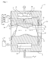
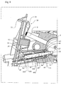
- Fig. 1 is a schematic view showing a fuel supply unit in the form of a diaphragm carburettor.
- the carburettor main body 1 has a main air passage 3 extending from an air inlet side 23 to an air outlet side 24. Air is drawn from an air inlet side 23 of the main body 1 via a choke valve 10, a venturi 11, and followed by a throttle valve 8, 9, towards the air outlet side 24 of the main body 1, as indicated by the arrows.
- the main body 1 has six sides; the air inlet side 23 opposite to the air outlet side 24, a fuel pump side 4 opposite to a fuel regulator side 5, and a first shaft side 6 opposite to a second shaft side 7.
- the throttle valve 8, 9 and choke valve 10 are preferably of butterfly type with a valve shaft and a valve plate, the throttle plate numbered 9 and the throttle shaft 8.
- the bore for the throttle shaft 8 is numbered 110 and the bore for the choke valve 111.
- a fuel pump 20 is located on the fuel pump side 4 of the main body, and draws fuel from a fuel tank 22.
- the fuel pump may be a known pulsation controlled diaphragm pump, driven by the pressure pulse generated by a crankcase of the engine that the carburettor is supplying air and fuel mixture to.
- the fuel pump 20 delivers fuel, via a needle valve 21, to a fuel metering chamber 18 of a fuel regulator 17 located at the opposite fuel regulator side 5.
- the fuel mitering chamber 18 is separated from atmospheric pressure by a diaphragm 19 and can hold a predetermined amount of fuel.
- the fuel valve 60 opens or closes the interconnection between the fuel metering chamber 18 and the fuel lines 28, 29, leading to the main air passage 3.
- the smaller channel 28 leads to an idle nozzle 12 downstream the throttle valve 8, 9 and the coarser channel 29 leads to a principal nozzle 13 upstream the throttle valve 8, 9. Due to the varying pressures in the main air passage 3 as the engine operates fuel is drawn from the fuel metering chamber 18 through the main nozzle 13 and the idle nozzle 12; of course when the fuel valve 60 is closed fuel is prevented from being drawn from the fuel metering chamber 18.
- the fuel valve 60 is controlled by an electronic control unit 100, that receives sensor inputs such as throttle position from a throttle positions sensor(s) 30; 300, engine speed from an engine speed sensor(s) 101, and optionally additional sensor(s) 102 such as e.g. a temperature sensor(s).
- the electronic control unit 100 can use these sensor inputs to decide when to open or close the fuel valve 60.
- the electronic control unit 100 may also control an air bleed valve 40, for bypassing air over the throttle valve 8, 9.
- the electronic control unit 100 is also arranged to transfer information to an ignition system of the internal combustion engine, the information being obtained from monitoring the status of at least one of the means 30; 300, 40, 60, and said ignition system being arranged to control the ignition timing with respect to said information.
- the electronic control unit 100 may also be arranged to transfer information to an ignition system of the internal combustion engine, the information being obtained from monitoring the status of the throttle position detecting means 30; 300, and said ignition system being arranged to control the ignition timing with respect to said information.
- the ignition system may be arranged to control the ignition timing at the idle state of the internal combustion engine in order to control the idle speed.
- the fuel valve 60 and the main parts of the air bleed valve 40 and the throttle position sensor 30; 300 are preferably mounted in a control module 2.
- the electronic control unit 100 (only indicated in Fig.1 ) 40, as well as corresponding electrical components, e.g. capacitor(s), are mounted in the control module 2, thereby the control module 2 can be assembled separately from the carburettor, i.e. on separate production lines.
- the control module 2 is mounted to the second shaft side 7, however it would also be possible to mount it on the first shaft side 6 or the fuel regulator side 5, of course then the path of the fuel lines 27, 28, 29 in the main body 1 must be changed.
- the control module 2 does preferably consist of one single unit but can of course be split into several units, which units can be mounted on different sides 4, 5, 6, 7 of the fuel supply unit 1.
- the direction 'front' and 'rear' are in relation to the main body 1 of the carburettor, where the term 'front' refers to elements at the end facing the main body 1 and 'rear' refers to elements at the opposite end.
- the fuel valve 60 includes a valve body 73 with an axially extending chamber 63, an axially moveable plunger 61 including a permanent magnet 62, electromagnetically operating means 68a, 68b for exerting a magnetic force to snap the plunger 61 between an open and a closed position when energized., and two opposite located ferromagnetic elements 66, 67 at each longitudinal end of the chamber 63.
- the axially extending chamber 63 extends in a direction away from the main body 1 and has two opposite located valve seats 64, 65 limiting the axial movement of the plunger 61, a front valve seat 64 at the longitudinal end facing the main body 1, and a rear valve seat 65 at the opposite longitudinal end.
- At the longitudinal end facing the main body 1 there are also provided two ports, a first port 71 and second port 72, one of them 72 functioning as an inlet port to the fuel valve and the other 71 as an outlet port to the fuel valve 60.
- the ports are fluidly connected to one another when the fuel valve 60 is open, forming a fluid passage between them.
- the first port 71 preferably the inlet, is enabled as an opening in the front valve seat 64 and connects to the fuel line 27 which has a connecting opening at the second shaft side 7 of the main body 1.
- the front end of the plunger 61 has a cross-section adapted to close the opening of the first port 71.
- the first port 71 is preferably a channel of circular cross-section connecting to the fuel line 27.
- the second port 72 preferably the outlet, is enabled beside the front valve seat 64, and connects to the fuel lines 28, 29 which have a common connecting opening at the second shaft side 7 of the main body 1.
- each valve seat 64, 65 there is a ferromagnetic element 66, 67, a front ferromagnetic element 66 and a rear ferromagnetic element 67, preferably in the form of iron cores.
- These ferromagnetic elements 66, 67 serve to provide two stable valve positions, an open position when the plunger 61 abuts the rear valve seat 65 and a closed position when the plunger 61 abuts the front valve seat 64. At the closed position the front end of the plunger 61 closes the first port 71 at the front valve seat 64, preventing fluid from flowing between the first 71 and the second port 72.
- the front ferromagnetic element 66 at least partly surrounds the channel of the first port 71, preferably in a form of an iron tube around the channel. I.e. preferably the front ferromagnetic element 66 provides a section of the channel of the first port 71.
- the magnet 62 of the plunger 61 is at least a section of the plunger 61; preferably the entire plunger 61 is a magnet 62.
- the magnet 62 of the plunger 61 is magnetically oriented in the longitudinal direction, having a front magnetic pole 62a facing the front valve seat 64 which interacts with the front ferromagnetic element 66, and a rear magnetic pole 62b facing the rear valve seat 65 which interacts with the rear ferromagnetic element 67.
- the magnetic forces between the magnet 62 and respectively ferromagnetic element 66, 67 are controlled so that the magnetic force between the front pole 62a and the front ferromagnetic element 66 is stronger than the magnetic force between the rear pole 62b and the rear ferromagnetic element 67 when the plunger 61 abuts the front valve seat 64 and so that the magnetic force between the rear pole 62b and the rear ferromagnetic element 67 is stronger than the magnetic force between the front pole 62a and the front ferromagnetic element 66 when the plunger 61 abuts the rear valve seat 65.
- the magnetic forces between the magnet 62 and respectively ferromagnetic element 66, 67 are controlled by distancing them from direct contact with one another, by separating them through a front respectively rear non-magnetic material 69, 70 of the front respectively rear valve seats 64, 65.
- the main reason for this is to avoid direct contact between the ferromagnetic element 66, 67 with the magnet 62, since the magnetic force between a ferromagnetic element and a magnet is exponentially growing the closer they are; hence by distancing them the slope of the force curve between them is not as steep as if they were in direct contact, why the tolerances in the production do not need to be as high as if they were not distanced.
- the distancing could of course be enabled by having a non magnetic material at respectively end of the plunger 61 instead of encapsulating the ferromagnetic element 66, 67 in the valve seats 64, 65. If the distancing insulating material is too thin, there is a risk that it will wear off, whereby the magnetic force would increase drastically.
- the distancing material is a polymer having a thickness in the range of 0.3-3 mm, more preferably 0.5-2 mm.
- the plunger is preferably cylindrical having a diameter in the range of 2-12 mm, more preferred 3-8 mm and preferably having a length larger than the diameter.
- the electromagnetically operating means 68a, 68b are provided by two solenoid coils 68a, 68b wound around the axially extending chamber 63 of the valve body 73.
- the solenoid coils 68a, 68b are wound at opposite winding directions to one another, where a first 68a of the two solenoids coils 68a, 68b are for snapping from open to closed position and a second of the two solenoids 68b are for snapping from closed to open.
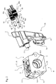
- the air bleed valve 40 will now be described in relation to Figs. 2-3, 5, 6 and 8 .
- the air bleed valve 40 includes a valve body 52 with an axially extending chamber 43, an axially moveable plunger 41 including a permanent magnet 42, electromagnetically operating means 48a, 48b for exerting a magnetic force to snap the plunger 41 between an open and a closed position when energized, and two opposite located ferromagnetic elements 46, 47 at each longitudinal end of the chamber 43.
- the axially extending chamber 43 extends in a direction away from the main body 1 and has two opposite located valve seats 44, 45 limiting the axial movement of the plunger 41, a front valve seat 44 at the longitudinal end facing the main body 1, and a rear valve seat 45 at the opposite longitudinal end.
- the plunger 41 includes a front section 54 made in a non-magnetic material, preferably a polymeric material, and a rear section 55, the rear section 55 including the magnet 42.
- the front section 54 protrudes through a valve seat aperture 51 in the front valve seat 44, which valve seat aperture 51 has a cross-section large enough for the front section 54 to protrude through but small enough to prevent the rear section 55 from protruding.
- the throttle valve plate 9 has a valve plate aperture 25 in the rim of the valve plate 9, and the main body 1 of the carburettor has a bore 26 leading to the main air passage 3, so that when the plunger 41 and the throttle valve 8, 9 are in their closed positions, the front end 53 of the plunger front section 54 is adapted to mainly fill said valve plate aperture 25.
- the front end 53 is retracted from the valve plate aperture 25, allowing an air bleed flow through the throttle valve 8, 9 even when it is closed.
- the area of the valve plate aperture 25 is preferably within in the range of 1-12 mm 2 , more preferably in the range of 2-8 mm 2 .
- each valve seat 44, 45 there is a ferromagnetic element 46, 47, front ferromagnetic element 46 and a rear ferromagnetic element 47, preferably in the form of iron cores.
- These ferromagnetic elements 46, 47 serve to provide two stable valve positions, an open position when the rear section 55 of the plunger 41 abuts the rear valve seat 45 and a closed position when the rear section 55 of the plunger 41 abuts the front valve seat 44.
- the front ferromagnetic element 46 at least partly surrounds the valve seat aperture 51, preferably in a form of an iron tube around the aperture. I.e. preferably the front ferromagnetic element 46 provides at least a section of the aperture.
- the magnet 42 of the plunger 41 is at least a section of the rear section 55, preferably almost the entire rear section 55 apart from the front end of the rear section 55 which preferably is of a nonmagnetic material functioning as a front distancing element 49, distancing the magnet 42 from the front ferromagnetic element 46.
- the magnet 42 is magnetically oriented in the longitudinal direction, having a front magnetic pole 42a facing the front valve seat 44 which interacts with the front ferromagnetic element 46, and a rear magnetic pole 42b facing the rear valve seat 45 which interacts with the rear ferromagnetic element 47.
- the magnetic forces between the magnet 42 and respectively ferromagnetic element 46, 47 are controlled so that the magnetic force between the front pole 42a and the front ferromagnetic element 46 is stronger than the magnetic force between the rear pole 42b and the rear ferromagnetic element 47 when the plunger 41 abuts the front valve seat 44 and so that the magnetic force between the rear pole 42b and the rear ferromagnetic element 47 is stronger than the magnetic force between the front pole 42a and the front ferromagnetic element 46 when the plunger 41 abuts the rear valve seat 45.
- the front section 54 of the plunger 41 is preferably of a nonmagnetic material, more preferably a polymeric material.
- the magnetic forces between the magnet 42 and respectively ferromagnetic element 46, 47 are controlled by distancing them from direct contact with one another. Therefore the rear valve 45 seat comprises a distancing rear nonmagnetic material 50 in front of the rear ferromagnetic element 47.
- the front valve seat 44 does not need to be covered by a nonmagnetic material since the front end of the rear section which contacts the front wall seat is nonmagnetic.
- the distancing material is a polymer having a thickness in the range of 0.3-3 mm, more preferably 0.5-2 mm.
- the rear section 55 of the plunger 41 is preferably cylindrical having a diameter in the range of 2-12 mm, more preferred 3-8 mm and preferably having a length larger than the diameter.
- the electromagnetically operating means 48a, 48b are provided by two solenoid coils 48a, 48b wound around the axially extending chamber 43 of the valve body 52.
- the solenoid coils 48a, 48b are wound at opposite winding directions to one another, where a first 48a of the two solenoids coils 48a, 48b are for snapping from open to closed position and a second of the two solenoids 48b are for snapping from closed to open.
- a first 48a of the two solenoids coils 48a, 48b are for snapping from open to closed position and a second of the two solenoids 48b are for snapping from closed to open.
- the energy consumption of the bypass air valve is kept low since it only needs to be energized when snapping between closed and open positions.
- a bistable bypass air valve which consumes low energy it is possible to actively use it during idle to compensate for different conditions affecting the engine performance, such as for instant fuel quality, air pressure, condition of the air filter, internal friction, etc.
- the start can be helped by having the air bleed valve open.
- having the fuel valve bistable as described above is beneficial for the energy consumption of the machine using them.
- the throttle position sensor 30 of a first embodiment includes a movable portion 34, which substantially has the shape of a cup being split in halves along a central plane.
- the movable portion 34 is movable in relation to the fuel supply unit 1 and a fixed portion 33, shown in figs. 2-6 and 8 , and the movable portion 34 being connected to a throttle shaft 8, as being shown in fig. 8 .
- Said throttle shaft 8 is fixedly connected to a throttle valve plate 9 of a throttle valve 8, 9 of a carburettor of an internal combustion engine.
- the throttle position sensor 30 is advantageously connected to a protruding end of the throttle shaft 8 on one side of the fuel supply unit 1, as being shown in fig. 8 .
- the throttle position sensor 30 could also be connected to both ends of the throttle shaft 8, or to some other means, that rotates in response to e.g. a throttle lever.
- the throttle shaft 8 is part of a throttle valve 8, 9 and fixedly connected to a throttle valve plate 9.
- the throttle valve 8, 9 shown in Fig 1 and 8 is of butterfly type and has two end positions, representing an open and a closed position, which positions in turn correspond to the idle and the full throttle states of the internal combustion engine. In the first embodiment the end positions are separated by an angular distance of approximately 75°, but this may of course vary. Between the two end positions is the part throttle range.
- the movable portion 34 and the throttle shaft 8 can be fixedly connected or connected through motion transfer elements to have an adapted motion.
- the movable portion 34 can e.g. be arranged to rotate 180° between the two end positions of the throttle shaft 8 and the throttle valve 8, 9.
- Such motion transfer elements are not shown in the figures.
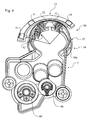
- the fixed portion 33 is fixed in relation to the movable portion 34 and being provided with pairs of one magnetic flux generating means 31 and one magnetic sensing element 32.
- the magnetic sensing element 32 being actuated by the magnetic flux of the magnetic flux generating means 31 of the same pair when the magnetic flux is not shielded by a magnetic flux guide 35.
- the magnetic flux guide 35 is connected to or a part of the movable portion 34.
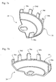
- the magnetic flux guide 35 of said embodiment includes five teeth 36a-e, as is shown in figs. 7a-b , and rotates with the movable portion 34 between the two end positions of the throttle valve 8, 9 along a substantially circular motion path.
- the motion path can be arranged to be substantially linear.
- the teeth 36a-e of the magnetic flux guide 35 are arranged to shield and thereby weaken the magnetic flux density at a magnetic sensing element 32 from the magnetic flux from a magnetic flux generating means 31.
- the teeth 36a-e can be arranged to intensify the magnetic flux density at a magnetic sensing element 32.
- the magnetic flux generating means 31 and the magnetic sensing elements 32 can be positioned on the same side of the motion path of the magnetic flux guide 35.
- a magnetic sensing element 32 gets actuated when a tooth 36a-e is in a position where said tooth 36a-e forms a magnetic circuit together with the magnetic flux generating means 31.
- the magnetic flux density is strengthened because of the lowered reluctance for the magnetic circuit when passing a tooth 36a-e instead of an air gap.
- the magnetic sensing element 32 is arranged to be actuated by the strengthened magnetic flux for certain positions of the magnetic flux guide 35 and therefore also for certain positions of the throttle valve 8, 9.
- the magnetic sensing element 32 is a digital hall sensor 32, which is able to generate one of two possible outputs, actuated or not actuated, depending on the magnetic flux density, e.g. generating the digital value '1' for flux density above a threshold value and '0' for flux density below said threshold value.
- the first embodiment of the throttle position sensor 30 includes three magnets 31 and three digital hall sensors 32 which are arranged in three pairs, each pair including one magnet 31 and one digital hall sensor 32.
- Each hall sensor 32 being configured to generate one of two possible values, actuated or not actuated.
- a pair can include more than one magnet 31 and more than one hall sensor 32, e.g. for improved reliability.
- the magnets 31 and the hall sensors 32 are mounted on the fixed portion 33 of the throttle position sensor 30.
- the teeth 36a-e of the magnetic flux guide 35 thus moves with the throttle shaft 8 and in relation to the fixed portion 33.
- the magnetic flux guide 35 has a motion path going through each of the three pairs of one magnet 31 and one hall sensor 32.
- Each detectable position of the throttle position sensor 30 corresponds to a state of the throttle position sensor 30.
- the state is formed by the states of all hall sensors 32 together.
- the states corresponding to idle and full throttle are unique but the states corresponding to the part throttle range are not unique, which means the same state can occur several times within the part throttle range.
- each state of each set of three successive states within the part throttle range is unique in relation to the other two states. This makes it possible to detect the direction of a change within the part throttle range.
- a throttle position sensor 30 according to this embodiment allows the possibility to indicate idle, full throttle and part throttle and the direction of change within the part throttle.
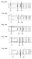
- a throttle position sensor 30 with three hall sensors 32 and three magnets 31 can have possible states of three values ranging from '000' to '111', the values representing the values of a first, a second and a third hall sensor 32.
- three magnets 31 and three hall sensors 32 and a magnetic flux guide 35 with five teeth 36a-e at least thirteen states can be obtained.
- the two unique states of the two end positions of the throttle valve 8, 9 are '000' and '011' for said embodiment, but can of course be inverted or in other ways altered.
- the first hall sensor 32 represented by the left most value, has the value '0' only for the idle and full throttle states. This is a convenient way of ensuring unique states of the throttle position sensor 30. This means, however, that the states '010' and '001' are not used. Alternatively, the configuration is altered to use also these states.
- the part throttle range corresponds to the following eleven states:
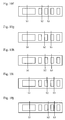
- a configuration with a magnetic flux guide 35 with six teeth 36a-e would add one of such series, a magnetic flux guide 35 with seven teeth 36a-e would add two series, etc. The opposite will apply for removing teeth 36a-e.
- a magnetic flux guide 35 with four teeth 36a-e would imply that the number of series is decremented by one, and for three teeth 36a-e, decremented by two.
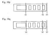
- FIG. 10a-q A schematic view of a magnetic flux guide 35 with six teeth 36a-e and five gaps is shown in fig. 10a-q ., wherein the five gaps are represented by five apertures.
- Fig 10a-q further show 17 positions of the magnetic flux guide 35, wherein each position represents a possible state of the throttle position sensor 30, and the three lines indicated by S1-S3 represent the positions of three pairs of one hall sensor 32 and one magnet 31.
- a line across an aperture implies that the hall sensor 32 is not shielded from the magnet 31 and therefore actuated, which further means a digital value '1' is generated by the hall sensor 32.
- 10a shows the right most position of the magnetic flux guide 35, which corresponds to idle.
- the magnets 31 and hall sensors 32 are mounted on the movable portion 34 and the magnetic flux guide 35 is mounted on the fixed portion 33.
- the configuration of the magnetic flux guide 35 can be altered in many ways, to provide another order of possible states or to have more possible states or less possible states.
- the configuration can e.g. be inverted, i.e. the teeth 36a-e in figs 7a-7b can be changed into gaps and the gaps can be changed into teeth 36a-e, whereby also the possible states of the throttle position sensor 30 are inverted.
- the magnets 31 are mounted on the movable portion 34 and the digital hall sensors 32 are mounted on the fixed portion 33 and no magnetic flux guide 35 is used.
- the movable portion 34 may be configured in a similar manner to the configuration in fig 7a-b , wherein each tooth 36a-e can be changed into a magnet 31 or a magnet 31 can be mounted onto each tooth 36a-e, but preferably the movable portion 34 has a more disc like configuration.
- Each hall sensor 32 is configured to generate one value for a magnetic flux density above a threshold value and a second value for below said threshold value.
- the magnetic flux density at a hall sensor 32 is above said threshold value when a magnet 31 and the hall sensor 32 are at certain positions in relation to each other and preferably when the magnet 31 and the hall sensor 32 are separated by a short distance or the shortest possible distance.
- two digital hall sensors 32 and at least one magnet 31 must be used.
- more magnets 31 are used, e.g. five, and three hall sensors 32.
- the number of possible states of such configuration of the embodiment corresponds to the number of possible states of the throttle position sensor 30 according to the first embodiment of the throttle position sensor 30.
- the first state, '111', and the last, '100' are unique and correspond to the end positions of the throttle valve 8, 9 and the idle and the full throttle states of the internal combustion engine.
- the states are inverted in relation to the states of the first embodiment.
- the possible states of the throttle position sensor 30 can easily be arranged in another order, states can be added, removed or inverted, the throttle position still having at least a first and second unique state, representing the both end positions of the throttle valve 8, 9 and therefore also the idle and the full throttle states of the internal combustion engine.
- the throttle position sensor 30 has a series of possible states corresponding to the part throttle range, enabling the throttle positions sensor 30 to indicate idle, part throttle, full throttle and the direction of change within the part throttle range.
- the magnets 31 are mounted on the fixed portion 33 and the hall sensors 32 on the movable portion 34.
- No magnetic flux guide 35 is used and there has to be at least two hall sensors 32 and at least one magnet 31 to detect the two unique positions of the throttle shaft 8 and the throttle valve 8, 9, corresponding to the idle and the full throttle state of the internal combustion engine.
- the magnetic sensing element 320 is an analogous hall device 320 mounted to the fixed portion 33, which fixed portion is not shown in fig. 11 and 12 .
- the analogous hall device has a hall element 321 which is configured to generate an output voltage that is proportional to the magnetic flux density through the hall element 321.
- the hall effect device 320 can have an integrated circuit for e.g. compensating for different conditions, such as temperature changes.
- the movable portion 340 has a substantially disc-like shape and is attached to the throttle shaft 8 at its centre and has two magnets 310 being polarized in a direction preferably perpendicular to the fixed portion.
- the movable portion 340 can of course be configured differently, e.g. having a triangular shape, or being provided with only one magnet 310 or more than two magnets 310.
- the magnets 310 are secured to the movable portion 340 at a distance from the axis of rotation and the magnets 310 are separated by approximately 75°.
- the two magnets 310 are polarized in opposite direction in relation to each other, so as to form a magnetic flux density through the hall element 321 of the hall effect device 320 that is substantially proportional to the size of rotation of the movable portion 340 and the throttle shaft 8. Consequently, the analogous hall sensor 320 generates an output voltage being approximately linear in relation to size of rotation of the throttle shaft 8 and the throttle valve 8, 9. With this kind of hall effect device 320 an accurate value of the position of the throttle valve 8, 9 can be derived also within the part throttle range.
- the output value of the throttle position sensor 300 can vary in different embodiments or configurations of the throttle position sensor 300.
- the throttle position sensor 300 is arranged to transfer data to-an electronic control unit 100, where more processing or all processing can be done.
- the output of the throttle position sensor 300 which also can be referred to as the status of the throttle position sensor 300, preferably is the hall voltage of the hall element 321 of the hall effect device 320.
- the output value can be processed together with e.g. the rotation speed of the internal combustion engine, a measured value of the air/fuel mix and/or temperature etc, in order to optimize the air/fuel mixture to the internal combustion engine.
- an adaptivity feature is built-in in the electronic control unit 100, in order to at least improve the accuracy for detecting a closed or a full open throttle valve.
- the electronic control unit 100 controls two threshold values that will be altered during engine operation to adapt to the real values corresponding to a closed and a full open throttle valve 8, 9, which real values in turn correspond to the maximum and the minimum output values of the throttle position sensor 300 and can be denoted by Vmax and Vmin.
- Vmax and Vmin will vary under influence of different conditions, such as different temperatures or stray magnetic fields.
- the electronic control unit 100 is therefore arranged to measure Vmax and Vmin during engine operation.
- the electronic control unit 100 can e.g. use information about the engine speed, and/or how long time the engine speed has been constant to conclude whether the maximum or the minimum value of the throttle position sensor 300 has been reached.
- the electronic control unit 100 only updates the maximum value when a value has been measured that is greater than the yet greatest measured value, and the minimum value is updated when a lower value than the yet lowest measured value is detected.
- the threshold values are recalculated to adapt to the measured real values.
- the difference between a threshold value and the respective real value is preferably less than 10% of S.
- the electronic control unit 100 uses default threshold values, which means the difference between a threshold value and the corresponding real value are greater at engine start and some time thereafter.
- the output of the throttle position sensor 300 is greater than the greatest threshold value a closed throttle valve is detected and when the output is smaller than the smallest threshold value a full open throttle valve is detected.
- the greatest threshold value will correspond to the full open position and the smallest threshold value will correspond to the closed position.
- the electronic control unit 100 controls three threshold values that are derived from Vmax and Vmin during engine operation; the third threshold value is e.g. in the middle of the span S, so as to divide the span into four sub-ranges, of which two are used for detecting full throttle and idle, and the other two for detecting a lower part of part throttle and a higher part of part throttle.
- the electronic control unit 100 controls more than three threshold values so as to form more than four discrete positions, e.g. ten discrete positions. The more discrete positions, the better accuracy when detecting throttle position.
- the adaptivity feature is used for deriving a continous output value.
- V the output value of the throttle position sensor
- D the angular displacement of the throttle valve
- h and k are constants.
- the adaptivity feature is very beneficial since it compensates not only for conditions such as temperature variations or stray magnetic fields, but also for variations among throttle position sensors.
- the throttle position sensors will vary from unit to unit because of manufacturing tolerances.
- the adaptivity enables less critical tolerances which in turn enables less costly units.
- a preferred embodiment of the ignition system includes a flywheel with magnets and electromagnetic converting means, which electromagnetic converting means is arranged to convert magnetic energy into electrical energy, which electrical energy is used both for the ignition and for powering the means 30; 300, 40, 60, 100 in the control module 2 or at least one of the means 30; 300, 40, 60, 100 in the control module 2 and/or also components not located in the control module 2.
- the flywheel includes a first and a second magnet separated by approximately 180°. The magnets periodically energize a first electromagnetic converting means, preferably a primary coil, as the flywheel rotates and the magnet moves near the coil.
- the primary coil preferably energizes a second electromagnetic converting means, the secondary coil, which has a winding with a greater number of turns of wire compared to the primary coil.
- adding a load to the secondary coil enables a very high voltage, suitable for ignition.
- electrical energy for powering is taken from the primary coil, after being energized by at least the first of the two magnets, but preferably also after being energized by the second magnet, and electrical energy for ignition is taken from the secondary coil, which secondary coil has been energized by the primary coil.
- the flywheel is provided with only one magnet or more than two magnets which can be separated by less than 180° and the at least one electromagnetic converting means can have other configurations but still being configured to convert magnetic energy to electrical energy both for ignition and powering.
- the output voltage of at least one of the at least one electromagnetic converting means in the ignition system is used for powering at least one of the means 30; 300, 40, 60, 100, which electromagnetic converting means has been energized by at least one of the magnet groups and the electrical energy for powering is taken from the ignition system in such manner that the amount of energy for the ignition is not reduced.
- the flywheel has a first and a second magnet group, the first magnet group includes a first magnet and the second magnet group includes a second magnet and the first and the second magnet being separated by an angular distance of at least 90°, the magnetic energy from the first magnet is used for the ignition and the magnetic energy from at least one of the first and the second magnet is used for powering at least one of the means 30; 300, 40, 60, 100.
- the ignition system of the internal combustion engine may at least partly include, or be in communication with, an electronic control unit 100, the ignition system being able to control the ignition timing for the internal combustion engine.
- the ignition system may be arranged to receive information from the electronic control unit 100 about the status of at least one of the means 30; 300, 40, 60 and said ignition system may be arranged to control the ignition timing at least with respect to the status of at least one of the means 30; 300, 40, 60.
- the ignition system may be arranged to control the ignition timing at least with respect to the status of the throttle position detecting means 30; 300.
- the ignition system may be arranged to control the idle speed through the control of the ignition timing of the internal combustion engine.
Landscapes
- Engineering & Computer Science (AREA)
- General Engineering & Computer Science (AREA)
- Mechanical Engineering (AREA)
- Chemical & Material Sciences (AREA)
- Combustion & Propulsion (AREA)
- Physics & Mathematics (AREA)
- General Physics & Mathematics (AREA)
- Electromagnetism (AREA)
- Electrical Control Of Air Or Fuel Supplied To Internal-Combustion Engine (AREA)
- Magnetically Actuated Valves (AREA)
- Electrical Control Of Ignition Timing (AREA)
- Combined Controls Of Internal Combustion Engines (AREA)
- Control Of The Air-Fuel Ratio Of Carburetors (AREA)
- Control Of Throttle Valves Provided In The Intake System Or In The Exhaust System (AREA)
Claims (15)
- Kraftstoffversorgungssystem für einen Verbrennungsmotor eines tragbaren Elektrowerkzeugs, wobei der Verbrennungsmotor einen Leerlauf- und einen Volllastzustand aufweist und das Kraftstoffsystem Folgendes umfasst:- eine Kraftstoffversorgungseinheit (1) in Form eines Vergasers oder eines Niederdruckeinspritzsystems,- ein Steuergerät (100) und- einen Drosselklappensensor (300) zum Erkennen der Stellung einer Drosselklappe (8, 9) und ihrer Drosselklappenwelle (8) in der Kraftstoffversorgungseinheit (1), wobei der Drosselklappensensor (300) Folgendes umfasst:- einen ortsfesten Abschnitt (33), der in Bezug auf die Kraftstoffversorgungseinheit (1) ortsfest ist,- einen beweglichen Abschnitt (340), der in Bezug auf den ortsfesten Abschnitt (33) und die Kraftstoffversorgungseinheit (1) beweglich ist und sich mit der Drosselklappenwelle (8) mitbewegt, wenn sie sich dreht,- mindestens ein Magnetflusserzeugungsmittel (310), wie einen Magneten, zum Erzeugen eines magnetischen Flusses,- ein Magnetsensorelement (320), wie einen analogen Hall-Sensor, zum Erkennen des von dem Magnetflusserzeugungsmittel (310) erzeugten magnetischen Flusses, wobei die Drosselklappenwelle (8) und der bewegliche Abschnitt (340) ortsfest miteinander oder über Bewegungsübertragungselemente für eine angepasste Bewegung verbunden sind und das Magnetflusserzeugungsmittel (310) an einem der beiden Abschnitte (33, 340), d.h. dem ortsfesten (33) oder dem beweglichen Abschnitt (340), und das Magnetsensorelement (320) so an dem anderen der beiden Abschnitte (33, 340) montiert ist, dass das Magnetsensorelement (320) und somit auch der Drosselklappensensor (300) je nach der Stellung des beweglichen Abschnitts (340) und somit auch der Stellung der Drosseklappenwelle (8) und der Drosselklappe (8, 9) kontinuierliche Werte erzeugen, wobei das Magnetsensorelement (320) und das Magnetflusserzeugungsmittel (310) so angeordnet sind, dass die magnetische Flussdichte am Magnetsensorelement (320) bei Winkelverschiebung des beweglichen Abschnitts (340) und somit auch bei Winkelverschiebung der Drosselklappenwelle (8) und der Drosselklappe (8, 9) auf im Wesentlichen lineare Weise variiert, wobei der Drosselklappensensor (300) mit einem elektronischen Steuergerät (100) in Verbindung steht, das angeordnet ist, um den Ausgabewert des Drosselklappensensors (300) zu verarbeiten, wobei das elektronische Steuergerät (100) angeordnet ist, um zumindest gelegentlich den höchsten und den niedrigsten Wert des Drosselklappensensors (300) zu speichern, wobei von diesen beiden Werten ein erster Wert einer geschlossenen Stellung der Drosselklappe (8, 9) und ein zweiter Wert der vollständig geöffneten Stellung der Drosselklappe (8, 9) entspricht, wobei die elektronische Steuergerät (100) den höchsten Wert des Drosselklappensensors (300) mit einem höchsten Schwellwert und den niedrigsten Wert des Drosselklappensensors (300) mit einem niedrigsten Schwellwert vergleicht und die Schwellwerte im Verlauf des Betriebs des Motors zum Anpassen des höchsten und des niedrigsten Werts des Drosselklappensensors (300) dynamisch so erhöht oder verringert werden, dass der höchste Schwellwert niedriger ist als der höchste Wert des Drosselklappensensors (300) und der niedrigste Schwellwert höher ist als der niedrigste Wert des Drosselklappensensors (300), wobei das elektronische Steuergerät (100) Schwellwerte regelt, die im Verlauf des Motorbetriebs geändert werden, um sie an die tatsächlichen Ausgangshöchst- und -tiefstwerte Vmax und Vmin des Drosselklappensensors anzupassen, wobei ein Wert des Drosselklappensensors (300) über dem höchsten Schwellwert oder unter dem niedrigsten Schwellwert von dem elektronischen Steuergerät (100) entweder als geschlossene oder vollständig geöffnete Stellung der Drosselklappe (8, 9) interpretiert wird.
- Kraftstoffversorgungssystem nach Anspruch 1, bei dem der Drosselklappensensor (300) mindestens zwei Magnetflusserzeugungsmittel (310) aufweist.
- Kraftstoffversorgungssystem nach einem der Ansprüche 1 und 2, bei dem das/ die Magnetflusserzeugungsmittel (310) an dem beweglichen Abschnitt (340) montiert ist/ sind und das Magnetsensorelement (320) an dem ortsfesten Abschnitt (33) montiert ist.
- Kraftstoffversorgungssystem nach einem der Ansprüche 1 und 2, bei dem das/ die Magnetflusserzeugungsmittel (310) an dem ortsfesten Abschnitt (33) montiert ist/ sind und das Magnetsensorelement (320) an dem beweglichen Abschnitt (340) montiert ist.
- Kraftstoffversorgungssystem nach einem der Ansprüche 1 bis 4, bei dem der höchste und der niedrigste Wert des Magnetsensorelements (320) den beiden Endstellungen der Drosselklappenwelle (8) und der Drosselklappe (8, 9) entsprechen, die wiederum dem Leerlauf- und dem Volllastzustand des Verbrennungsmotors entsprechen.
- Kraftstoffversorgungssystem nach einem der Ansprüche 1 bis 5, bei dem das Magnetsensorelement (320) einen analogen Hall-Sensor und das Magnetflusserzeugungsmittel (310) einen Magneten aufweist.
- Kraftstoffversorgungssystem nach Anspruch 6, bei dem das elektronische Steuergerät (100) mindestens drei Schwellwerte so regelt, dass die Ausgabewerte des Drosselklappensensors (300) in mindestens vier Teilbereiche unterteilt werden, wobei jeder Teilbereich für eine Stellung des Drosselklappensensors (300) steht.
- Kraftstoffversorgungssystem nach einem der Ansprüche 1 bis 7, bei dem die Beziehung zwischen dem Wert des Drosselklappensensors (300) und der Winkelverschiebung der Drosselklappe (8, 9) im Wesentlichen linear ist und somit die Gleichung V=kD+h oder D=(V-h)/k beschreibt, in der V der Ausgabewert des Drosselklappensensors (300) ist, D die Winkelverschiebung der Drosselklappe (8, 9) ist und h und k Konstanten sind, wobei der Drosselklappensensor (300) mit dem elektronischen Steuergerät (100) in Verbindung steht, das angeordnet ist, um zumindest gelegentlich den höchsten und den niedrigsten Wert des Drosselklappensensors (300) zu messen, wobei diese beiden Werte den beiden Endstellungen der Drosselklappe (8, 9) entsprechen und es dem elektronischen Steuergerät (100) ermöglichen, die Konstanten h und k im Verlauf des Motorbetriebs neu zu berechnen, wodurch das elektronische Steuergerät (100) in der Lage ist, die Messung der Winkelverschiebung der Drosselklappe (8, 9) an aktuelle Bedingungen anzupassen.
- Kraftstoffversorgungssystem nach einem der Ansprüche 1 bis 8, bei dem der Drosselklappensensor (300) mit dem elektronischen Steuergerät (100) in Verbindung steht, das Bestandteil eines Steuermoduls (2) oder damit verbunden ist und Bestandteil eines Zündsystems mit regelbarer Zündzeitpunkteinstellung ist oder in Verbindung damit steht, wobei das elektronische Steuergerät (100) angeordnet ist, um den aktuellen Status des Drosselklappensensors (300) zu dem Zündsystem zu senden, das Zündsystem angeordnet ist, um die Zündzeitpunkteinstellung in Bezug auf den Status des Drosselklappensensors (300) zumindest für den Leerlaufzustand zu regeln, um die Leerlaufdrehzahl zu regeln.
- Kraftstoffversorgungseinheit (1) in Form eines Vergasers oder eines Niederdruckeinspritzsystems eines Verbrennungsmotors mit dem Kraftstoffversorgungssystem nach einem der Ansprüche 1 bis 9, die Folgendes umfasst:- einen Lufthauptkanal (3), der eine darin montierte Drosselklappe (8, 9) mit einer Drosselklappenwelle (8) aufweist, die zwischen zwei einander gegenüberliegenden Wellenseiten (6, 7) verläuft, und ein Steuermodul (2) für die Kraftstoffversorgung (2), das an einer (7) der Wellenseiten (6, 7) montiert ist, wobei das Steuermodul (2) Folgendes aufweist:- Kraftstoffventilmittel (60) zum Regeln der Kraftstoffversorgung des Lufthauptkanals (3) und- einen Drosselklappensensor (300) zum Überwachen der Stellung der Drosselklappe (8, 9).
- Steuermodul (2) für die Kraftstoffversorgungseinheit (1) mit dem Kraftstoffversorgungssystem nach Anspruch 9, wobei das Steuermodul (2), wie z.B. ein Vergaser oder ein Niederdruckeinspritzsystem eines Verbrennungsmotors, Folgendes aufweist:- Kraftstoffventilmittel (60) zum Regeln der Kraftstoffversorgung des Lufthauptkanals (3) und- einen Drosselklappensensor (300) zum Überwachen der Stellung einer Drosselklappe (8, 9), der in einem Lufthauptkanal (3) der Kraftstoffversorgungseinheit (1) montiert ist.
- Zündsystem eines Verbrennungsmotors mit dem Kraftstoffversorgungssystem nach einem der Ansprüche 1 bis 9, wobei das Zündsystem angeordnet ist, um die Zündzeitpunkteinstellung für den Verbrennungsmotor zumindest in Bezug auf den Status des Drosselklappensensors (300) des Kraftstoffversorgungssystems zu regeln,
wobei das Zündsystem mit dem elektronischen Steuergerät (100) in Verbindung steht, in der Lage ist, die Zündzeitpunkteinstellung für den Verbrennungsmotor zu regeln, und angeordnet ist, um von dem elektronischen Steuergerät (100) Informationen über den Status des Drosselklappensensors (300), eines Kraftstoffventils (60) oder/ und eines Luftventils (40) zu empfangen. - Drosselklappensensor (30) zum Erkennen der Stellung einer Drosselklappe (8, 9) und ihrer Drosselklappenwelle (8) in einer Kraftstoffversorgungseinheit (1), wie z.B. einem Vergaser oder einem Niederdruckeinspritzsystem, eines Verbrennungsmotors, wobei der Verbrennungsmotor einen Leerlauf- und einen Volllastzustand aufweist und der Drosselklappensensor (30) Folgendes umfasst:- mindestens ein Magnetflusserzeugungsmittel (31), wie einen Magneten, zum Erzeugen eines magnetischen Flusses,- mindestens ein Magnetsensorelement (32), wie einen digitalen Hall-Sensor, zum Erkennen der von dem Magnetflusserzeugungsmittel (31) erzeugten magnetischen Flussdichte, wobei das Magnetsensorelement (32) so konfiguriert ist, dass es in Abhängigkeit davon, ob die magnetische Flussdichte einen Schwellwert erreicht hat oder nicht, einen von zwei möglichen Werten erzeugt,- einen ortsfesten Abschnitt (33), der in Bezug auf die Kraftstoffversorgungseinheit (1) ortsfest ist,- einen beweglichen Abschnitt (34), der in Bezug auf den ortsfesten Abschnitt (33) und die Kraftstoffversorgungseinheit (1) beweglich ist, wobei sich der bewegliche Abschnitt (34) mit der Drosselklappenwelle (8) mitbewegt, wenn diese sich dreht, wobei das Magnetsensorelement (32) und somit auch der Drosselklappensensor (30) angeordnet sind, um einen eindeutigen Wert zu erzeugen, wenn sie von dem Magnetflusserzeugungsmittel (31) in einer ersten Endstellung des beweglichen Abschnitts (34) betätigt werden, die einer Endstellung der Drosselklappenwelle (8) und der Drosselklappe (8, 9) entspricht,dadurch gekennzeichnet, dass die Drosselklappenwelle (8) und der bewegliche Abschnitt (34) fest miteinander oder über Bewegungsübertragungselemente für eine angepasste Bewegung verbunden sind und jedes Magnetsensorelement (32) so konfiguriert ist, dass es in Abhängigkeit von der magnetischen Flussdichte einen von zwei möglichen Werten erzeugt, und mindestens zwei Magnetflusserzeugungsmittel (31) und die mindestens zwei Magnetsensorelemente (32) an dem ortsfesten Abschnitt (33) montiert sind und ein Magnetflussleiter (35) so an dem beweglichen Abschnitt (34) montiert oder Bestandteil davon ist, dass er (35) sich mit der Drosselklappenwelle (8) und der Drosselklappe (8, 9) mitbewegt, und der Magnetflussleiter (35) so angeordnet ist, dass er die magnetische Flussdichte an einem Magnetsensorelement (32) verstärkt oder abschwächt, so dass die Magnetsensorelemente (32) und somit auch der Drosselklappensensor (30) sowohl für die erste als auch für die zweite Endstellung des beweglichen Abschnitts (34) eindeutige Werte erzeugen, wobei die Endstellungen des beweglichen Abschnitts (34) den beiden vorgegebenen Endstellungen der Drosselklappenwelle (8) und der Drosselklappe (8, 9) entsprechen, die wiederum dem Leerlauf- und dem Volllastzustand des Verbrennungsmotors entsprechen.
- Drosselklappensensor (30) nach Anspruch 13, bei dem der Magnetflussleiter (35) mindestens zwei und vorzugsweise mindestens drei Zähne (36a-e) umfasst und der Drosselklappensensor (30) angeordnet ist, um zwischen mindestens vier oder vorzugsweise mindestens fünf Stellungen der Drosselklappenwelle (8) und der Drosselklappe (8, 9) zu unterscheiden, bei denen mindestens zwei Stellungen eindeutigen Zuständen des Drosselklappensensors (30) entsprechen und für die beiden Endstellungen der Drosselklappenwelle (8) und somit auch für die Endstellungen der Drosselklappe (8, 9) stehen, während die anderen mindestens zwei oder vorzugsweise mindestens drei Stellungen für den Teillastbereich des Verbrennungsmotors stehen.
- Drosselklappensensor (300) zum Erkennen der Stellung einer Drosselklappe (8, 9) und ihrer Drosselklappenwelle (8) in einer Kraftstoffversorgungseinheit (1) in Form eines Vergasers oder eines Niederdruckeinspritzsystems eines Kraftstoffversorgungssystems nach einem der Ansprüche 1 bis 9 für einen Verbrennungsmotor, wobei der Verbrennungsmotor einen Leerlauf- und einen Volllastzustand aufweist, wobei der Drosselklappensensor (300) Folgendes umfasst:- einen ortsfesten Abschnitt (33), der in Bezug auf die Kraftstoffversorgungseinheit (1) ortsfest ist,- einen beweglichen Abschnitt (340), der in Bezug auf den ortsfesten Abschnitt (33) und die Kraftstoffversorgungseinheit (1) beweglich ist und sich mit der Drosselklappenwelle (8) mitbewegt, wenn sie sich dreht,- mindestens ein Magnetflusserzeugungsmittel (310), wie einen Magneten, zum Erzeugen eines magnetischen Flusses,- ein Magnetsensorelement (320), wie einen analogen Hall-Sensor, zum Erkennen des von dem Magnetflusserzeugungsmittel (310) erzeugten magnetischen Flusses, wobei die Drosselklappenwelle (8) und der bewegliche Abschnitt (340) ortsfest miteinander oder über Bewegungsübertragungselemente für eine angepasste Bewegung verbunden sind und das Magnetflusserzeugungsmittel (310) an einem der beiden Abschnitte (33, 340), d.h. dem ortsfesten (33) oder dem beweglichen Abschnitt (340), und das Magnetsensorelement (320) so an dem anderen der beiden Abschnitte (33, 340) montiert ist, dass das Magnetsensorelement (320) und somit auch der Drosselklappensensor (300) je nach der Stellung des beweglichen Abschnitts (340) und somit auch der Stellung der Drosselklappenwelle (8) und der Drosselklappe (8, 9) kontinuierliche Werte erzeugt, wobei das Magnetsensorelement (320) und das Magnetflusserzeugungsmittel (310) so angeordnet sind, dass die magnetische Flussdichte am Magnetsensorelement (320) bei Winkelverschiebung des beweglichen Abschnitts (340) und somit auch bei Winkelverschiebung der Drosselklappenwelle (8) und der Drosselklappe (8, 9) auf im Wesentlichen lineare Weise variiert, wobei der Drosselklappensensor von einem Zündsystem angetrieben wird, das Folgendes umfasst:- ein Schwungrad des Verbrennungsmotors, das mit einem ersten und einem zweiten Schwungradmagneten versehen ist, die um einen Winkelabstand von mindestens 90 Grad voneinander getrennt sind, und- ein elektromagnetisches Umwandlungsmittel, vorzugsweise eine Spule, zum Umwandeln von magnetischer Energie in Elektroenergie,wobei die Schwungradmagneten, während sich das Schwungrad dreht und sich die Schwungradmagneten in der Nähe des elektromagnetischen Umwandlungsmittels bewegen, das elektromagnetische Umwandlungsmittel periodisch erregen, wobei die Ausgangsspannung des elektromagnetischen Umwandlungsmittels zum Antreiben des Drosselklappensensors (300) benutzt wird, so dass die magnetische Energie von dem ersten oder/ und dem zweiten Magneten zum Antreiben des Drosselklappensensors (300) benutzt wird.
Priority Applications (2)
| Application Number | Priority Date | Filing Date | Title |
|---|---|---|---|
| EP10189356.8A EP2290217B1 (de) | 2008-03-17 | 2008-03-17 | Brennstoffversorgungseinheit |
| PL10189356.8T PL2290217T3 (pl) | 2008-03-17 | 2008-03-17 | Jednostka podająca paliwo |
Applications Claiming Priority (3)
| Application Number | Priority Date | Filing Date | Title |
|---|---|---|---|
| EP08724238.4A EP2268911B1 (de) | 2008-03-17 | 2008-03-17 | Kraftstoffversorgungseinheit |
| EP10189356.8A EP2290217B1 (de) | 2008-03-17 | 2008-03-17 | Brennstoffversorgungseinheit |
| PCT/SE2008/050291 WO2009116902A1 (en) | 2008-03-17 | 2008-03-17 | Fuel supply unit |
Related Parent Applications (3)
| Application Number | Title | Priority Date | Filing Date |
|---|---|---|---|
| EP08724238.4 Division | 2008-03-17 | ||
| EP08724238.4A Division EP2268911B1 (de) | 2008-03-17 | 2008-03-17 | Kraftstoffversorgungseinheit |
| EP08724238.4A Division-Into EP2268911B1 (de) | 2008-03-17 | 2008-03-17 | Kraftstoffversorgungseinheit |
Publications (3)
| Publication Number | Publication Date |
|---|---|
| EP2290217A2 EP2290217A2 (de) | 2011-03-02 |
| EP2290217A3 EP2290217A3 (de) | 2012-08-08 |
| EP2290217B1 true EP2290217B1 (de) | 2016-03-16 |
Family
ID=41091138
Family Applications (2)
| Application Number | Title | Priority Date | Filing Date |
|---|---|---|---|
| EP10189356.8A Active EP2290217B1 (de) | 2008-03-17 | 2008-03-17 | Brennstoffversorgungseinheit |
| EP08724238.4A Active EP2268911B1 (de) | 2008-03-17 | 2008-03-17 | Kraftstoffversorgungseinheit |
Family Applications After (1)
| Application Number | Title | Priority Date | Filing Date |
|---|---|---|---|
| EP08724238.4A Active EP2268911B1 (de) | 2008-03-17 | 2008-03-17 | Kraftstoffversorgungseinheit |
Country Status (5)
| Country | Link |
|---|---|
| US (1) | US8950381B2 (de) |
| EP (2) | EP2290217B1 (de) |
| CN (1) | CN101978152B (de) |
| PL (1) | PL2290217T3 (de) |
| WO (1) | WO2009116902A1 (de) |
Families Citing this family (21)
| Publication number | Priority date | Publication date | Assignee | Title |
|---|---|---|---|---|
| IES20120149A2 (en) * | 2011-03-23 | 2012-06-20 | Barcarole Ltd | Electronic fuel control system |
| EP2697498B1 (de) * | 2011-04-15 | 2018-10-31 | Husqvarna AB | Vergasersystem für einen vergasermotor |
| US9605599B2 (en) | 2011-08-08 | 2017-03-28 | Husqvarna Ab | Magnet holder for use in a throttle position sensor, a magnet holder for use in an angular position sensor, and methods for manufacturing them |
| WO2013089599A1 (en) | 2011-12-13 | 2013-06-20 | Husqvarna Ab | Engine and a shut down method for an engine |
| EP2823468A4 (de) | 2012-03-08 | 2015-12-23 | Husqvarna Ab | System und verfahren für motordrehzahldatenverwendung |
| US9986311B2 (en) | 2012-03-08 | 2018-05-29 | Husqvarna Ab | Automated operator-equipment pairing system and method |
| CN103032206B (zh) * | 2013-01-04 | 2015-05-20 | 陈其安 | 一步起动式化油器 |
| US8838367B1 (en) * | 2013-03-12 | 2014-09-16 | Mcalister Technologies, Llc | Rotational sensor and controller |
| JP6487631B2 (ja) * | 2014-05-21 | 2019-03-20 | 株式会社やまびこ | 層状掃気式2サイクル内燃エンジン |
| CN203962200U (zh) * | 2014-07-25 | 2014-11-26 | 浙江瑞星化油器制造有限公司 | 一种带有燃气转换阀结构的多燃料化油器 |
| JP6659701B2 (ja) * | 2014-12-23 | 2020-03-04 | フスクバルナ アクティエボラーグ | 内燃機関を安全に始動する組立体及び方法 |
| DE102016214252A1 (de) * | 2016-08-02 | 2018-02-08 | Festo Ag & Co. Kg | Ventilbetätigungssystem |
| SE541417C2 (en) * | 2017-06-12 | 2019-09-24 | Husqvarna Ab | A carburetor assembly start setting detection arrangement |
| US11008951B2 (en) * | 2017-10-02 | 2021-05-18 | Walbro Llc | Low pressure fuel injection system for a multi-cylinder light-duty internal combustion engine |
| WO2019112961A1 (en) | 2017-12-04 | 2019-06-13 | Holley Performance Products, Inc. | Electronic fuel injection throttle body assembly |
| DE102018000145A1 (de) * | 2018-01-10 | 2019-07-11 | Andreas Stihl Ag & Co. Kg | Vergaser für den Verbrennungsmotor in einem handgeführten Arbeitsgerät, Verbrennungsmotor mit einem Vergaser und Verfahren zum Betrieb eines Verbrennungsmotors |
| WO2019143915A1 (en) * | 2018-01-19 | 2019-07-25 | Walbro Llc | Fuel control system |
| US10655748B2 (en) | 2018-07-13 | 2020-05-19 | Bendix Commercial Vehicle Systems Llc | Magnetic latching solenoid valve |
| SE542749C2 (en) | 2018-12-04 | 2020-07-07 | Sem Ab | Crankshaft driven flywheel magneto generator with circular winding for power supply in handheld batteryless combustion engines |
| CN111692016B (zh) * | 2019-03-13 | 2024-07-23 | 华益机电有限公司 | 一种燃油供给系统 |
| CN115875506B (zh) * | 2023-02-06 | 2023-05-02 | 泉州昆泰芯微电子科技有限公司 | 阀门开度检测装置及管道输送控制装置 |
Family Cites Families (39)
| Publication number | Priority date | Publication date | Assignee | Title |
|---|---|---|---|---|
| US2094860A (en) * | 1932-12-23 | 1937-10-05 | Continental Motors Corp | Engine |
| US2614584A (en) * | 1947-05-23 | 1952-10-21 | Skinner Chuck Company | Solenoid actuated valve |
| GB1491883A (en) * | 1974-05-24 | 1977-11-16 | Yamaha Motor Co Ltd | Four stroke internal combustion engine |
| FR2282043A1 (fr) | 1974-08-12 | 1976-03-12 | Yamaha Motor Co Ltd | Moteur a combustion interne |
| US4306589A (en) * | 1980-01-09 | 1981-12-22 | The Aro Corporation | Low power solenoid-operated air valve with magnetic latching |
| DE3026133A1 (de) * | 1980-07-10 | 1982-02-18 | Robert Bosch Gmbh, 7000 Stuttgart | Elektromagnetisches ventil |
| JPS57148060A (en) * | 1981-03-10 | 1982-09-13 | Sanshin Ind Co Ltd | Ignition timing control of internal combustion engine |
| DE3507443A1 (de) * | 1985-03-02 | 1986-09-04 | Robert Bosch Gmbh, 7000 Stuttgart | Elektromagnetisch betaetigbares kraftstoffeinspritzventil |
| US4690371A (en) * | 1985-10-22 | 1987-09-01 | Innovus | Electromagnetic valve with permanent magnet armature |
| US4794890A (en) | 1987-03-03 | 1989-01-03 | Magnavox Government And Industrial Electronics Company | Electromagnetic valve actuator |
| JP2671147B2 (ja) * | 1989-01-31 | 1997-10-29 | スズキ株式会社 | 船舶用エンジンの点火時期制御方式 |
| DE3905992A1 (de) * | 1989-02-25 | 1989-09-21 | Mesenich Gerhard | Elektromagnetisches hochdruckeinspritzventil |
| SE464588B (sv) * | 1989-09-11 | 1991-05-13 | Svenska Electromagneter | Anordning vid svaenghjulsmagneter, saerskilt foer flercylindriga foerbraenningsmotorer |
| IT1245634B (it) * | 1990-06-28 | 1994-09-29 | Ducati Meccanica Spa | Generatore con sistema di alimentazione per l'accensione elettronica nei motori a combustione interna |
| JPH0833110B2 (ja) * | 1990-08-08 | 1996-03-29 | 本田技研工業株式会社 | アクセルペダル位置センサ及びスロットル弁位置センサ間の誤差修正装置 |
| AU4276093A (en) * | 1992-08-10 | 1994-03-03 | Lean Burn Associates, Inc. | Dilution controlled lean burn system |
| US5954494A (en) | 1993-08-19 | 1999-09-21 | Mi-T-M Corporation | Pressure washer blower ignition electrical system |
| SE503907C2 (sv) | 1994-05-05 | 1996-09-30 | Electrolux Ab | Förfarande och anordning för bränslereglering vid en förbränningsmotor |
| US5479890A (en) * | 1994-10-07 | 1996-01-02 | Diesel Engine Retarders, Inc. | Compression release engine brakes with electronically controlled, multi-coil hydraulic valves |
| JPH08304011A (ja) * | 1995-05-15 | 1996-11-22 | Mikuni Corp | 磁気式角度センサ |
| US6068010A (en) * | 1995-06-09 | 2000-05-30 | Marotta Scientific Controls, Inc. | Microvalve and microthruster for satellites and methods of making and using the same |
| US6047165A (en) * | 1995-11-14 | 2000-04-04 | Harris Corporation | Wireless, frequency-agile spread spectrum ground link-based aircraft data communication system |
| US5904131A (en) * | 1995-12-28 | 1999-05-18 | Cummins Engine Company, Inc. | Internal combustion engine with air/fuel ratio control |
| DE19739358A1 (de) * | 1997-09-09 | 1999-03-25 | Kostal Leopold Gmbh & Co Kg | Winkelsensor |
| US6604497B2 (en) * | 1998-06-05 | 2003-08-12 | Buehrle, Ii Harry W. | Internal combustion engine valve operating mechanism |
| US6199587B1 (en) * | 1998-07-21 | 2001-03-13 | Franco Shlomi | Solenoid valve with permanent magnet |
| US7021603B2 (en) * | 1998-10-08 | 2006-04-04 | Wladyslaw Wygnaski | Electromagnetic actuator and integrated actuator and fluid flow control valve |
| US6948697B2 (en) * | 2000-02-29 | 2005-09-27 | Arichell Technologies, Inc. | Apparatus and method for controlling fluid flow |
| US6351704B1 (en) * | 2000-03-31 | 2002-02-26 | Bombardier Motor Corporation Of America | Method and apparatus for calibrating a position sensor used in engine control |
| EP1321745A4 (de) * | 2000-09-25 | 2005-09-07 | Tokai Rika Co Ltd | Drehwinkeldetektor |
| JP4060177B2 (ja) * | 2002-12-25 | 2008-03-12 | 株式会社日立製作所 | 内燃機関の制御装置 |
| JP3926763B2 (ja) * | 2003-04-22 | 2007-06-06 | 株式会社ケーヒン | 内燃機関の制御システム |
| JPWO2005040730A1 (ja) * | 2003-10-29 | 2007-11-22 | 株式会社ミツバ | 回転角検出装置 |
| US7347191B2 (en) * | 2004-06-22 | 2008-03-25 | Ti Group Automotive Systems, L.L.C. | Vehicle fuel system |
| JP4428163B2 (ja) * | 2004-07-20 | 2010-03-10 | 株式会社デンソー | バルブ位置制御装置 |
| JP2006125344A (ja) * | 2004-10-29 | 2006-05-18 | Toyota Motor Corp | 内燃機関の制御装置 |
| DE102004060714A1 (de) * | 2004-12-17 | 2006-07-06 | Pierburg Gmbh | Schaltklappeneinrichtung |
| DE102005050338A1 (de) * | 2005-10-20 | 2007-05-03 | Siemens Ag | Verfahren zum Überprüfen eines Ventils |
| JP4513890B2 (ja) * | 2008-04-03 | 2010-07-28 | トヨタ自動車株式会社 | 電磁弁 |
-
2008
- 2008-03-17 PL PL10189356.8T patent/PL2290217T3/pl unknown
- 2008-03-17 EP EP10189356.8A patent/EP2290217B1/de active Active
- 2008-03-17 US US12/922,951 patent/US8950381B2/en active Active
- 2008-03-17 EP EP08724238.4A patent/EP2268911B1/de active Active
- 2008-03-17 CN CN2008801281537A patent/CN101978152B/zh not_active Expired - Fee Related
- 2008-03-17 WO PCT/SE2008/050291 patent/WO2009116902A1/en not_active Ceased
Also Published As
| Publication number | Publication date |
|---|---|
| EP2268911A1 (de) | 2011-01-05 |
| EP2268911B1 (de) | 2017-01-04 |
| EP2290217A3 (de) | 2012-08-08 |
| CN101978152B (zh) | 2013-07-03 |
| PL2290217T3 (pl) | 2016-12-30 |
| US8950381B2 (en) | 2015-02-10 |
| WO2009116902A1 (en) | 2009-09-24 |
| US20110095215A1 (en) | 2011-04-28 |
| EP2268911A4 (de) | 2012-08-08 |
| CN101978152A (zh) | 2011-02-16 |
| EP2290217A2 (de) | 2011-03-02 |
Similar Documents
| Publication | Publication Date | Title |
|---|---|---|
| EP2290217B1 (de) | Brennstoffversorgungseinheit | |
| EP0900329B1 (de) | Automatisches fluidkontrollsystem mit druckbalanziertem elektromagnetventil | |
| CN101984762B (zh) | 发动机燃料输送系统、设备和方法 | |
| US20230087858A1 (en) | Low pressure fuel and air charge forming device for a combustion engine | |
| WO1998008014A1 (en) | Fuel injection valve and engine including the same | |
| GB1418932A (en) | Fuel injection systems | |
| EP2835520B1 (de) | Kraftstoffeinspritzvorrichtung und Verfahren zum Betreiben einer Kraftstoffeinspritzvorrichtung | |
| US20050061302A1 (en) | Purge valve including a permanent magnet linear actuator | |
| US4387696A (en) | Electromagnetically controlled fuel injection system | |
| CN111133181A (zh) | 用于多缸轻型内燃发动机的低压燃料喷射系统 | |
| EP1929148B1 (de) | Positionssensor mit variabler reluktanz | |
| RU2456469C2 (ru) | Блок подачи топлива | |
| CN103216346B (zh) | 节流位置传感器、燃料供应单元及其控制模块、点火系统 | |
| GB2044541A (en) | Movable plunger type electromagnetic valve | |
| EP1452730A1 (de) | Zündzeitpunktsteuervorrichtung für einen verbrennungsmotor | |
| JP3946842B2 (ja) | 気化器の開度検出装置 | |
| US4873955A (en) | Idle air flow shutoff valve | |
| US12385457B2 (en) | Method of controlling a fuel injector | |
| EP1331389B1 (de) | Fahrzeugfluidkontrollsystem mit druckbalanziertem Elektromagnetventil | |
| US11885291B2 (en) | Low pressure fuel injection system for a combustion engine | |
| JPH0244049Y2 (de) | ||
| JPS6157454B2 (de) |
Legal Events
| Date | Code | Title | Description |
|---|---|---|---|
| PUAI | Public reference made under article 153(3) epc to a published international application that has entered the european phase |
Free format text: ORIGINAL CODE: 0009012 |
|
| 17P | Request for examination filed |
Effective date: 20101029 |
|
| AC | Divisional application: reference to earlier application |
Ref document number: 2268911 Country of ref document: EP Kind code of ref document: P |
|
| AK | Designated contracting states |
Kind code of ref document: A2 Designated state(s): AT BE BG CH CY CZ DE DK EE ES FI FR GB GR HR HU IE IS IT LI LT LU LV MC MT NL NO PL PT RO SE SI SK TR |
|
| AX | Request for extension of the european patent |
Extension state: AL BA MK RS |
|
| REG | Reference to a national code |
Ref country code: DE Ref legal event code: R079 Ref document number: 602008042978 Country of ref document: DE Free format text: PREVIOUS MAIN CLASS: F02M0017120000 Ipc: F02D0009100000 |
|
| PUAL | Search report despatched |
Free format text: ORIGINAL CODE: 0009013 |
|
| AK | Designated contracting states |
Kind code of ref document: A3 Designated state(s): AT BE BG CH CY CZ DE DK EE ES FI FR GB GR HR HU IE IS IT LI LT LU LV MC MT NL NO PL PT RO SE SI SK TR |
|
| AX | Request for extension of the european patent |
Extension state: AL BA MK RS |
|
| RIC1 | Information provided on ipc code assigned before grant |
Ipc: F02M 17/12 20060101ALI20120702BHEP Ipc: F16K 31/08 20060101ALI20120702BHEP Ipc: F16K 37/00 20060101ALI20120702BHEP Ipc: F02D 9/10 20060101AFI20120702BHEP Ipc: G01D 5/14 20060101ALI20120702BHEP Ipc: F02D 11/10 20060101ALI20120702BHEP |
|
| 17Q | First examination report despatched |
Effective date: 20130409 |
|
| GRAJ | Information related to disapproval of communication of intention to grant by the applicant or resumption of examination proceedings by the epo deleted |
Free format text: ORIGINAL CODE: EPIDOSDIGR1 |
|
| GRAP | Despatch of communication of intention to grant a patent |
Free format text: ORIGINAL CODE: EPIDOSNIGR1 |
|
| INTG | Intention to grant announced |
Effective date: 20151006 |
|
| GRAS | Grant fee paid |
Free format text: ORIGINAL CODE: EPIDOSNIGR3 |
|
| GRAA | (expected) grant |
Free format text: ORIGINAL CODE: 0009210 |
|
| AC | Divisional application: reference to earlier application |
Ref document number: 2268911 Country of ref document: EP Kind code of ref document: P |
|
| AK | Designated contracting states |
Kind code of ref document: B1 Designated state(s): AT BE BG CH CY CZ DE DK EE ES FI FR GB GR HR HU IE IS IT LI LT LU LV MC MT NL NO PL PT RO SE SI SK TR |
|
| REG | Reference to a national code |
Ref country code: GB Ref legal event code: FG4D |
|
| REG | Reference to a national code |
Ref country code: CH Ref legal event code: EP |
|
| REG | Reference to a national code |
Ref country code: IE Ref legal event code: FG4D |
|
| REG | Reference to a national code |
Ref country code: AT Ref legal event code: REF Ref document number: 781469 Country of ref document: AT Kind code of ref document: T Effective date: 20160415 |
|
| REG | Reference to a national code |
Ref country code: DE Ref legal event code: R096 Ref document number: 602008042978 Country of ref document: DE |
|
| REG | Reference to a national code |
Ref country code: FR Ref legal event code: PLFP Year of fee payment: 9 |
|
| REG | Reference to a national code |
Ref country code: SE Ref legal event code: TRGR |
|
| REG | Reference to a national code |
Ref country code: NL Ref legal event code: MP Effective date: 20160316 |
|
| REG | Reference to a national code |
Ref country code: LT Ref legal event code: MG4D |
|
| PG25 | Lapsed in a contracting state [announced via postgrant information from national office to epo] |
Ref country code: HR Free format text: LAPSE BECAUSE OF FAILURE TO SUBMIT A TRANSLATION OF THE DESCRIPTION OR TO PAY THE FEE WITHIN THE PRESCRIBED TIME-LIMIT Effective date: 20160316 Ref country code: NO Free format text: LAPSE BECAUSE OF FAILURE TO SUBMIT A TRANSLATION OF THE DESCRIPTION OR TO PAY THE FEE WITHIN THE PRESCRIBED TIME-LIMIT Effective date: 20160616 Ref country code: FI Free format text: LAPSE BECAUSE OF FAILURE TO SUBMIT A TRANSLATION OF THE DESCRIPTION OR TO PAY THE FEE WITHIN THE PRESCRIBED TIME-LIMIT Effective date: 20160316 Ref country code: GR Free format text: LAPSE BECAUSE OF FAILURE TO SUBMIT A TRANSLATION OF THE DESCRIPTION OR TO PAY THE FEE WITHIN THE PRESCRIBED TIME-LIMIT Effective date: 20160617 |
|
| REG | Reference to a national code |
Ref country code: AT Ref legal event code: MK05 Ref document number: 781469 Country of ref document: AT Kind code of ref document: T Effective date: 20160316 |
|
| PG25 | Lapsed in a contracting state [announced via postgrant information from national office to epo] |
Ref country code: LT Free format text: LAPSE BECAUSE OF FAILURE TO SUBMIT A TRANSLATION OF THE DESCRIPTION OR TO PAY THE FEE WITHIN THE PRESCRIBED TIME-LIMIT Effective date: 20160316 Ref country code: BE Free format text: LAPSE BECAUSE OF NON-PAYMENT OF DUE FEES Effective date: 20160331 Ref country code: NL Free format text: LAPSE BECAUSE OF FAILURE TO SUBMIT A TRANSLATION OF THE DESCRIPTION OR TO PAY THE FEE WITHIN THE PRESCRIBED TIME-LIMIT Effective date: 20160316 Ref country code: LV Free format text: LAPSE BECAUSE OF FAILURE TO SUBMIT A TRANSLATION OF THE DESCRIPTION OR TO PAY THE FEE WITHIN THE PRESCRIBED TIME-LIMIT Effective date: 20160316 |
|
| PG25 | Lapsed in a contracting state [announced via postgrant information from national office to epo] |
Ref country code: IS Free format text: LAPSE BECAUSE OF FAILURE TO SUBMIT A TRANSLATION OF THE DESCRIPTION OR TO PAY THE FEE WITHIN THE PRESCRIBED TIME-LIMIT Effective date: 20160716 Ref country code: EE Free format text: LAPSE BECAUSE OF FAILURE TO SUBMIT A TRANSLATION OF THE DESCRIPTION OR TO PAY THE FEE WITHIN THE PRESCRIBED TIME-LIMIT Effective date: 20160316 |
|
| REG | Reference to a national code |
Ref country code: CH Ref legal event code: PL |
|
| PG25 | Lapsed in a contracting state [announced via postgrant information from national office to epo] |
Ref country code: RO Free format text: LAPSE BECAUSE OF FAILURE TO SUBMIT A TRANSLATION OF THE DESCRIPTION OR TO PAY THE FEE WITHIN THE PRESCRIBED TIME-LIMIT Effective date: 20160316 Ref country code: CZ Free format text: LAPSE BECAUSE OF FAILURE TO SUBMIT A TRANSLATION OF THE DESCRIPTION OR TO PAY THE FEE WITHIN THE PRESCRIBED TIME-LIMIT Effective date: 20160316 Ref country code: ES Free format text: LAPSE BECAUSE OF FAILURE TO SUBMIT A TRANSLATION OF THE DESCRIPTION OR TO PAY THE FEE WITHIN THE PRESCRIBED TIME-LIMIT Effective date: 20160316 Ref country code: PT Free format text: LAPSE BECAUSE OF FAILURE TO SUBMIT A TRANSLATION OF THE DESCRIPTION OR TO PAY THE FEE WITHIN THE PRESCRIBED TIME-LIMIT Effective date: 20160718 Ref country code: SK Free format text: LAPSE BECAUSE OF FAILURE TO SUBMIT A TRANSLATION OF THE DESCRIPTION OR TO PAY THE FEE WITHIN THE PRESCRIBED TIME-LIMIT Effective date: 20160316 Ref country code: AT Free format text: LAPSE BECAUSE OF FAILURE TO SUBMIT A TRANSLATION OF THE DESCRIPTION OR TO PAY THE FEE WITHIN THE PRESCRIBED TIME-LIMIT Effective date: 20160316 |
|
| REG | Reference to a national code |
Ref country code: DE Ref legal event code: R097 Ref document number: 602008042978 Country of ref document: DE |
|
| REG | Reference to a national code |
Ref country code: IE Ref legal event code: MM4A |
|
| PG25 | Lapsed in a contracting state [announced via postgrant information from national office to epo] |
Ref country code: BE Free format text: LAPSE BECAUSE OF FAILURE TO SUBMIT A TRANSLATION OF THE DESCRIPTION OR TO PAY THE FEE WITHIN THE PRESCRIBED TIME-LIMIT Effective date: 20160316 |
|
| PLBE | No opposition filed within time limit |
Free format text: ORIGINAL CODE: 0009261 |
|
| STAA | Information on the status of an ep patent application or granted ep patent |
Free format text: STATUS: NO OPPOSITION FILED WITHIN TIME LIMIT |
|
| PG25 | Lapsed in a contracting state [announced via postgrant information from national office to epo] |
Ref country code: LI Free format text: LAPSE BECAUSE OF NON-PAYMENT OF DUE FEES Effective date: 20160331 Ref country code: IE Free format text: LAPSE BECAUSE OF NON-PAYMENT OF DUE FEES Effective date: 20160317 Ref country code: CH Free format text: LAPSE BECAUSE OF NON-PAYMENT OF DUE FEES Effective date: 20160331 Ref country code: DK Free format text: LAPSE BECAUSE OF FAILURE TO SUBMIT A TRANSLATION OF THE DESCRIPTION OR TO PAY THE FEE WITHIN THE PRESCRIBED TIME-LIMIT Effective date: 20160316 |
|
| REG | Reference to a national code |
Ref country code: FR Ref legal event code: PLFP Year of fee payment: 10 |
|
| 26N | No opposition filed |
Effective date: 20161219 |
|
| PG25 | Lapsed in a contracting state [announced via postgrant information from national office to epo] |
Ref country code: BG Free format text: LAPSE BECAUSE OF FAILURE TO SUBMIT A TRANSLATION OF THE DESCRIPTION OR TO PAY THE FEE WITHIN THE PRESCRIBED TIME-LIMIT Effective date: 20160616 |
|
| GBPC | Gb: european patent ceased through non-payment of renewal fee |
Effective date: 20160616 |
|
| PG25 | Lapsed in a contracting state [announced via postgrant information from national office to epo] |
Ref country code: SI Free format text: LAPSE BECAUSE OF FAILURE TO SUBMIT A TRANSLATION OF THE DESCRIPTION OR TO PAY THE FEE WITHIN THE PRESCRIBED TIME-LIMIT Effective date: 20160316 Ref country code: GB Free format text: LAPSE BECAUSE OF NON-PAYMENT OF DUE FEES Effective date: 20160616 |
|
| PG25 | Lapsed in a contracting state [announced via postgrant information from national office to epo] |
Ref country code: IT Free format text: LAPSE BECAUSE OF FAILURE TO SUBMIT A TRANSLATION OF THE DESCRIPTION OR TO PAY THE FEE WITHIN THE PRESCRIBED TIME-LIMIT Effective date: 20160316 |
|
| PG25 | Lapsed in a contracting state [announced via postgrant information from national office to epo] |
Ref country code: MT Free format text: LAPSE BECAUSE OF FAILURE TO SUBMIT A TRANSLATION OF THE DESCRIPTION OR TO PAY THE FEE WITHIN THE PRESCRIBED TIME-LIMIT Effective date: 20160316 |
|
| REG | Reference to a national code |
Ref country code: FR Ref legal event code: PLFP Year of fee payment: 11 |
|
| PG25 | Lapsed in a contracting state [announced via postgrant information from national office to epo] |
Ref country code: CY Free format text: LAPSE BECAUSE OF FAILURE TO SUBMIT A TRANSLATION OF THE DESCRIPTION OR TO PAY THE FEE WITHIN THE PRESCRIBED TIME-LIMIT Effective date: 20160316 Ref country code: HU Free format text: LAPSE BECAUSE OF FAILURE TO SUBMIT A TRANSLATION OF THE DESCRIPTION OR TO PAY THE FEE WITHIN THE PRESCRIBED TIME-LIMIT; INVALID AB INITIO Effective date: 20080317 |
|
| PGFP | Annual fee paid to national office [announced via postgrant information from national office to epo] |
Ref country code: PL Payment date: 20180125 Year of fee payment: 11 Ref country code: SE Payment date: 20180219 Year of fee payment: 11 Ref country code: FR Payment date: 20180306 Year of fee payment: 11 |
|
| PG25 | Lapsed in a contracting state [announced via postgrant information from national office to epo] |
Ref country code: LU Free format text: LAPSE BECAUSE OF NON-PAYMENT OF DUE FEES Effective date: 20160317 Ref country code: TR Free format text: LAPSE BECAUSE OF FAILURE TO SUBMIT A TRANSLATION OF THE DESCRIPTION OR TO PAY THE FEE WITHIN THE PRESCRIBED TIME-LIMIT Effective date: 20160316 Ref country code: MT Free format text: LAPSE BECAUSE OF FAILURE TO SUBMIT A TRANSLATION OF THE DESCRIPTION OR TO PAY THE FEE WITHIN THE PRESCRIBED TIME-LIMIT Effective date: 20160331 Ref country code: MC Free format text: LAPSE BECAUSE OF FAILURE TO SUBMIT A TRANSLATION OF THE DESCRIPTION OR TO PAY THE FEE WITHIN THE PRESCRIBED TIME-LIMIT Effective date: 20160316 |
|
| REG | Reference to a national code |
Ref country code: SE Ref legal event code: EUG |
|
| PG25 | Lapsed in a contracting state [announced via postgrant information from national office to epo] |
Ref country code: SE Free format text: LAPSE BECAUSE OF NON-PAYMENT OF DUE FEES Effective date: 20190318 |
|
| PG25 | Lapsed in a contracting state [announced via postgrant information from national office to epo] |
Ref country code: FR Free format text: LAPSE BECAUSE OF NON-PAYMENT OF DUE FEES Effective date: 20190331 |
|
| PG25 | Lapsed in a contracting state [announced via postgrant information from national office to epo] |
Ref country code: PL Free format text: LAPSE BECAUSE OF NON-PAYMENT OF DUE FEES Effective date: 20190317 |
|
| P01 | Opt-out of the competence of the unified patent court (upc) registered |
Effective date: 20230419 |
|
| PGFP | Annual fee paid to national office [announced via postgrant information from national office to epo] |
Ref country code: DE Payment date: 20250218 Year of fee payment: 18 |