EP2289773A1 - Vehicle combination including a tractor vehicle, a trailer with a sliding drawbar and an axial guide device, and corresponding trailer - Google Patents
Vehicle combination including a tractor vehicle, a trailer with a sliding drawbar and an axial guide device, and corresponding trailer Download PDFInfo
- Publication number
- EP2289773A1 EP2289773A1 EP10173122A EP10173122A EP2289773A1 EP 2289773 A1 EP2289773 A1 EP 2289773A1 EP 10173122 A EP10173122 A EP 10173122A EP 10173122 A EP10173122 A EP 10173122A EP 2289773 A1 EP2289773 A1 EP 2289773A1
- Authority
- EP
- European Patent Office
- Prior art keywords
- trailer
- chassis
- towing vehicle
- vertical
- frame
- Prior art date
- Legal status (The legal status is an assumption and is not a legal conclusion. Google has not performed a legal analysis and makes no representation as to the accuracy of the status listed.)
- Granted
Links
- 239000000725 suspension Substances 0.000 claims description 49
- 230000000295 complement effect Effects 0.000 claims description 15
- 230000008878 coupling Effects 0.000 claims description 5
- 238000010168 coupling process Methods 0.000 claims description 5
- 238000005859 coupling reaction Methods 0.000 claims description 5
- 241000946381 Timon Species 0.000 description 6
- 230000005540 biological transmission Effects 0.000 description 3
- 230000000694 effects Effects 0.000 description 3
- 238000010276 construction Methods 0.000 description 2
- 238000004519 manufacturing process Methods 0.000 description 2
- 238000005096 rolling process Methods 0.000 description 2
- 125000006850 spacer group Chemical group 0.000 description 2
- ZZGXRPGQPAPARK-UWVGGRQHSA-N 3-[(5r,6r)-1-azabicyclo[3.2.1]octan-6-yl]-4-propylsulfanyl-1,2,5-thiadiazole Chemical compound C1([C@H]2CN3C[C@@]2(CCC3)[H])=NSN=C1SCCC ZZGXRPGQPAPARK-UWVGGRQHSA-N 0.000 description 1
- 101710092224 Phosphate propanoyltransferase Proteins 0.000 description 1
- 230000004913 activation Effects 0.000 description 1
- 230000000712 assembly Effects 0.000 description 1
- 238000000429 assembly Methods 0.000 description 1
- 230000002860 competitive effect Effects 0.000 description 1
- 238000006073 displacement reaction Methods 0.000 description 1
- 230000005484 gravity Effects 0.000 description 1
- 238000002360 preparation method Methods 0.000 description 1
- 239000003380 propellant Substances 0.000 description 1
Images


Classifications
-
- B—PERFORMING OPERATIONS; TRANSPORTING
- B62—LAND VEHICLES FOR TRAVELLING OTHERWISE THAN ON RAILS
- B62D—MOTOR VEHICLES; TRAILERS
- B62D53/00—Tractor-trailer combinations; Road trains
- B62D53/04—Tractor-trailer combinations; Road trains comprising a vehicle carrying an essential part of the other vehicle's load by having supporting means for the front or rear part of the other vehicle
-
- B—PERFORMING OPERATIONS; TRANSPORTING
- B60—VEHICLES IN GENERAL
- B60D—VEHICLE CONNECTIONS
- B60D1/00—Traction couplings; Hitches; Draw-gear; Towing devices
- B60D1/01—Traction couplings or hitches characterised by their type
- B60D1/04—Hook or hook-and-hasp couplings
-
- B—PERFORMING OPERATIONS; TRANSPORTING
- B60—VEHICLES IN GENERAL
- B60D—VEHICLE CONNECTIONS
- B60D1/00—Traction couplings; Hitches; Draw-gear; Towing devices
- B60D1/14—Draw-gear or towing devices characterised by their type
- B60D1/145—Draw-gear or towing devices characterised by their type consisting of an elongated single bar or tube
- B60D1/155—Draw-gear or towing devices characterised by their type consisting of an elongated single bar or tube comprising telescopic or foldable parts
-
- B—PERFORMING OPERATIONS; TRANSPORTING
- B60—VEHICLES IN GENERAL
- B60D—VEHICLE CONNECTIONS
- B60D1/00—Traction couplings; Hitches; Draw-gear; Towing devices
- B60D1/24—Traction couplings; Hitches; Draw-gear; Towing devices characterised by arrangements for particular functions
- B60D1/30—Traction couplings; Hitches; Draw-gear; Towing devices characterised by arrangements for particular functions for sway control, e.g. stabilising or anti-fishtail devices; Sway alarm means
-
- B—PERFORMING OPERATIONS; TRANSPORTING
- B62—LAND VEHICLES FOR TRAVELLING OTHERWISE THAN ON RAILS
- B62D—MOTOR VEHICLES; TRAILERS
- B62D63/00—Motor vehicles or trailers not otherwise provided for
- B62D63/06—Trailers
- B62D63/062—Trailers with one axle or two wheels
- B62D63/065—Trailers with one axle or two wheels forming an extension of the towing vehicle, i.e. with two point fixation
Definitions
- the present invention relates to a road assembly comprising a towing vehicle, a drawbar trailer, and an axially guided device between the towing vehicle and the trailer, and a corresponding trailer.
- Such an axial guide device makes it possible to produce a road assembly having the maximum possible payload (Permissible Total Rolling Weight) for a minimum footprint and a maneuverability equivalent to a non-articulated vehicle.
- the aim of the present invention is to propose a road assembly comprising an axially guided trailer, whose chassis is designed with a particular architecture implementing a combination of means, having the advantage, on the one hand, of being able to adapt to a large number of standard cab-type utility vehicle models on the market, regardless of the length of their wheelbase, the width of their lane or their shape, and without the need to shorten the rear of their chassis or use of a directional trailer axle to limit the shifting effect and, at the same time, to accommodate a large number of body models of length, width, height and payload variables corresponding to market standards.
- Such an axially guided trailer chassis, called “universal” has the other advantages of being mass-produced at a competitive price, and to be able to tackle a large number of standard commercial vehicles with a hitch kit and easy to install guide.
- the frame has a central portion carrying vertical wheel supports, the central portion and its vertical wheel supports straddle the rear portion of the frame of the towing vehicle so as to position a vertical wheel support longitudinally in the space that remains available on the outside of the rear of the chassis between it and the wheel of the trailer just behind a wheel of the rear axle of the towing vehicle.
- This frame structure according to the invention thus makes it possible to position the wheels of the trailer as close as possible to the rear wheels of the towing vehicle, in particular of the standard chassis cab-type towing vehicle, despite the bulk of the rear part of its chassis, and therefore of limit the effect of wheel shifting when cornering.
- the trailer further comprises a drawbar called sliding, inertia braking, fixed to the front of the trailer frame, and positioned to hook via its attachment means complementary to the attachment means fixed on the chassis of the towing vehicle, in front of its rear axle.
- sliding drawbar with inertia braking is associated with an inertial braking device comprising braking means arranged at the wheels of the trailer and controlled by the displacement of the movable part of the sliding drawbar via a system of braking. transmission, for example type linkage or hydraulic type.
- a sliding drawbar allows the realization of road trailers of economic construction up to a permissible total weight in load (PTAC) of 3,5T.
- the axial guiding device is composed of two parts capable of collaborating, one fixed to the frame of the towing vehicle, the other to the chassis of the trailer, which make it possible to maintain permanently the median longitudinal axis of the trailer in the plane. vertical longitudinal axis of its towing vehicle.
- This axial guiding device leaves free relative vertical movements of suspension and longitudinal braking and can leave free or not the roll movement of the trailer relative to its towing vehicle.
- This axial guiding device makes it possible to produce a road assembly having the maximum possible payload (PTRA, Permissible Total Rolling Weight) for a minimum footprint and a maneuverability equivalent to a non-articulated vehicle.
- PTRA Permissible Total Rolling Weight
- Various embodiments of axial guidance can be implemented.
- the axial guiding device is as described in the aforementioned patent document, or as described in the European patent application, filed July 9, 2009, under the No. 09165107.5 and entitled "Road Set".
- said first guide means of the towing vehicle are able to cooperate, substantially between the rear axle of the towing vehicle and the front axle. of the trailer, behind the front axle of the trailer, and / or in front of the rear axle of the towing vehicle, preferably substantially between said axles, with said second means for guiding the trailer to maintain the median longitudinal axis of the trailer; trailer and the vertical longitudinal plane of the tractor substantially merged and guide the pivoting of the trailer about said transverse axis of pitch.
- said central portion of the frame is formed by at least one so-called forward cross member and two vertical wheel supports mounted at the ends of said front cross member, the front cross member being arranged in the hooked position of the trailer, above the chassis of the towing vehicle.
- the frame of the trailer further comprises at least one spar mounted on the front cross member and carrying said fixed portion of the sliding drawbar.
- the vertical wheel supports are rigid parts constituting the chassis of the trailer, each wheel of the trailer can be mounted on a wheel support via a suspension system.
- said central portion further comprises a rear cross member, each wheel support is formed of a support spar mounted between said front cross member and said rear cross member, the axes of the wheels of the trailer being arranged between the front cross member. and the rear crossmember.
- each wheel support is formed of a hollow support spar comprising two vertical side walls, an upper wall and / or a lower wall.
- each wheel is mounted on a vertical wheel support by means of a pull-type or pushed-type swing arm pivotally mounted in the lower part of the vertical wheel support about a transverse axis of pivoting.
- said trailer comprises a suspension system comprising said pull-type or pushed push-type arms, supporting the wheels, connected by links to a resilient device offset towards the rear of the trailer frame, each link being mounted pivoting by a first end at the end of an arm integral in rotation with an oscillating arm and by a second end at the end of an axis of the elastic device resiliently biased towards a rest position.
- Such a suspension system with elastic elements deported backwards, thanks to a connection rods, makes it possible to reserve, behind the chassis chassis vehicles cab type chassis available on the market, when the trailer is in the hooked position, a free space which ensures that no part of the trailer can come hitting the chassis of the vehicle during use, particularly during the braking phases when the sliding drawbar is compressed and this regardless of the relative position of the suspensions of the assembly road in normal operation.
- said oscillating arms are pushed type, each oscillating arm extending towards the front of the trailer from its pivot axis in the lower part of the vertical wheel support.
- said vertical wheel supports are formed by the longitudinal suspension blades of a suspension system, each wheel is mounted at the end of a rigid transverse axle connected to the longitudinal suspension blades, the body central of said transverse axle being disposed under the frame of the towing vehicle in the hooked position of the trailer.
- the vertical wheel supports are formed by the suspension blades which extend downwards from the central part of the chassis, the transverse axle being positioned under the chassis of the towing vehicle in the hooked position.
- Each vertical wheel support may comprise at least one suspension blade fixed at its ends to a spar of the central part of the trailer frame, the central body of the transverse axle carrying at each end a substantially vertical axle arm on which is mounted a wheel and whereby the transverse axle is fixed to the central portion of the suspension blades.
- each vertical wheel support comprises at least one suspension blade fixed by its central part to a spar of the central part of the chassis of the trailer, the front and rear ends of the suspension blades carry transverse axles. tandem type bogie, the transverse axle of the trailer the further ahead coming under the chassis of the towing vehicle in the hooked position of the trailer.
- the frame of the trailer comprises a first pair of front longitudinal members, the sliding drawbar being mounted axially between the front ends of said front longitudinal members.
- the frame of the trailer comprises a first pair of telescopic front rails, mounted by first fastening means on the front cross member.
- the frame of the trailer comprises at least one rear spar telescopic relative to the central portion, longitudinally adjustable on the central portion carrying the wheels and adapted to be fixed rigidly longitudinally in position by second fastening means on the central part, in particular on the aforesaid rear cross member, and extending towards the rear of the chassis of the trailer, each rear spar being preferably assembled to each corresponding front spar by means of assembly .
- the frame of the trailer comprises a second pair of rear beams, each spar of the first and second pair being preferably assembled to a spar of the other pair by means of assembly.
- the frame of the trailer comprises a front end support beam, rigidly connected at its lower part, directly or indirectly, to the upper part of the front frame of the trailer frame.
- This front support beam fixed above the chassis side members makes it easier to hook the trailer to the towing vehicle by providing the minimum clear height required above the rear fenders of the towing vehicles to perform the hooking operation. and the free movement of its wheels when the camber of the trailer is very short.
- This front support cross member advantageously carries at its ends side crutches, removable, collapsible or retractable, which support the front weight of the trailer when it is uncoupled.
- the frame of the trailer is equipped with two supports rigidly fixed to the front support beam, adjustable transversely in position, for example during the camber and intended to receive the attachment of the front ends of the subframe of the body.
- These supports make it possible to fix the front ends of different subframes, regardless of the spacing of their side members, while leaving the outer side side space at the same height as their side members, unlike a transverse support continued.
- the released space allows free movement of the rear wheels of the vehicle and facilitates its engagement under the trailer.
- said chassis of the trailer is equipped with a bodywork provided with a subframe, the side members of the subframe being fixed directly on crossbars of the chassis of the trailer, on each side of the side members of said chassis.
- the spacing of the longitudinal members of a pair of longitudinal members of the chassis of the trailer preferably being at most equal to the spacing between the longitudinal members of the vehicle tractor.
- the chassis of the towing vehicle is equipped with a cross member, fixed on the chassis of the towing vehicle in front of its rear wheels, on which are fixed adjustably in height the hooking means.
- adjustable elastic stops mounted either on the chassis of the towing vehicle or on the chassis of the trailer, come into contact with complementary rigid parts mounted respectively on the frame of the trailer or on the chassis of the towing vehicle, respectively. together to adjust the height of free movement of the suspension of the trailer relative to the towing vehicle on the one hand and limit the amplitude of its movements relative to acceptable extreme positions on the other hand.
- the chassis of the towing vehicle comprises a rear underrun bar provided with retractable lateral end portions movable, for example by pivoting or sliding between an extended position in which said lateral end portions extend. laterally outwardly beyond the chassis, in particular spars, substantially to the level of the outer flanks of the rear wheels, and a retracted position in which said lateral end portions do not protrude laterally from the chassis, so as to leave Pass the wheels and the wheel supports of the trailer when hooking.
- the distance between the two vertical wheel supports, more precisely measured between their inner faces, is advantageously greater than or equal to 70 cm, to allow the positioning of said vertical wheel supports on either side of most of the vehicle chassis. tractor.
- FIGS 1 to 9 illustrate a road assembly according to the invention comprising a towing vehicle, of the commercial vehicle type, and a trailer, and whose trailer chassis can on the one hand, straddle the rear part of a large number of vehicles existing cab chassis type 3.5T commercial vehicles regardless of their wheelbases, tracks and shapes, and on the other hand be equipped with any type of bodywork whose length, width and payload are compatible with those authorized or possible for the road combinations thus formed.
- the simple construction of the frame and its universal character allows mass production.
- the tractor vehicle V comprises a cabin chassis 1, on which are mounted a front directional axle and a rear axle carrying rear wheels 11, the rear axle being for example rigid type, propellant or not, with a suspension system to spring blades arranged longitudinally or pull-arm type with a torsion bar suspension system, both types being known per se.
- the chassis is partly in front of a cabin 12 and the vehicle engine system.
- the frame 10 has a longitudinal plane of vertical symmetry represented on the figure 5 under the reference P1 and is formed for example of two longitudinal members 13, shown schematically on the figure 9 , connected parallel to each other by several sleepers (not shown).
- Each spar has a recessed U-shaped cross-section, with a vertically disposed flank 13a and inwardly oriented horizontal flanges 13b.
- Each spar can also be hollow box type of substantially rectangular section. It has in this case a vertical outer side and two sides, upper and lower, horizontal.
- the chassis has a so-called rear portion 10a which extends behind the rear wheels 11.
- the trailer R comprises a chassis C comprising a so-called central portion 3 carrying the wheels 58 of the trailer and comprising two wheel supports in the form of support rails 40 interconnected by a front cross member 31 and a rear cross member 32.
- Said support beams are of tubular type with a rectangular cross section, formed of two vertical, so-called outer 41a and inner 41b rigid lateral walls, interconnected by an upper wall 42 and a lower wall 43 ( Fig. 4 ), the front end of each spar being closed by a front wall 44, a rear wall 45 disposed under the rear cross member closing the rear ends of the support rails.
- Each wheel 58 is mounted on a support beam by means of an oscillating arm 50 or suspension arm, pivotally mounted at one end under the lower wall of the spar, between two vertical tabs 51, about a horizontal axis of rotation, and carrying at its other end the hub 57 of a wheel.
- the swing arms are bent outwardly so as to carry the hub and its wheel on the outer side of the outer side wall 41a.
- the swingarms are of drawn type, they extend backwards from their axis of rotation.
- Each swing arm is rotatably connected to an arm 52 to which is articulated a first end of a rod 53.
- the second ends of the rods are mounted articulated at the ends of an elastic device 54 disposed in the rear part of the central portion.
- the arms 52 pass through openings in the bottom wall 43 and extend inside the support rails.
- the rods arranged in the support rails are hinged to the ends of the elastic device 54 mounted between the support rails 40.
- the elastic device 54 is formed of a conventional trailer axle said rubber profile, comprising a square tube or substantially triangular fixed, mounted between the support rails, wherein is mounted at 45 ° a small square or substantially triangular tube, and four or three rubber profiles.
- the ends of the small square tube carry arms 55 provided with transverse pins 56 to which are articulated rods 53.
- the oscillating arms 50, the arms 52, the rods 53 and the elastic device form the suspension system 5 ( Fig. 5 ) of the trailer.
- the chassis further comprises a pair of front longitudinal members 61, 62 telescopic and a pair of telescopic rear beams 63, 64.
- the front longitudinal members are fixed by first attachment means 65, for example U-shaped jumpers, on the front cross member 31.
- the two front longitudinal members are fixed symmetrically on either side of the vertical longitudinal plane P2 ( Fig. 9 ) of the trailer.
- These front longitudinal members extend forward of the central portion and carry at their front end an axial sliding-type drawbar with inertia braking, said sliding drawbar 8, by means of a fixing plate 69.
- telescopic rear rails are fixed by second attachment means 66 on the rear cross member 32.
- Each rear spar extend towards the rear of the trailer frame and are arranged symmetrically on either side of the plane of symmetry P, between the side members before.
- Each rear spar is disposed against a front spar, to which it is assembled by means of assembly 67 at its front end and at the rear end of the front spar.
- the rear ends of the rear longitudinal members are advantageously connected by a rear crossmember 68.
- a front support beam 70 is fixed rigidly on the top of the front part of the front longitudinal members.
- the front support beam carries at the end of the side stands 71, removable, collapsible or retractable, which support the front weight of the trailer when it is uncoupled.
- the front support beam 70 also carries two narrow supports 72 rigidly fixed to the front cross member, adjustable transversely during the camber and intended to receive the fixing of the front ends of the subframe of the bodywork.
- the chassis C may be equipped with different types of bodywork, for example a bucket 9, tilting or non-tilting, as illustrated on the figures 1 and 4 .
- the bucket 9 is fixed by the longitudinal members 92 of its subframe 91 directly on the front crosspieces 31 and rear 32 of the central part and on the supports 72 of the front support beam, as visible on the figure 4 .
- the telescopic longitudinal members are fixed at a distance between them, such as the external lateral dimensions of the longitudinal members, and their fastening means. that is, less than the distance between the inner faces of the narrowest chassis chassis type utility vehicle frame rails 13 available on the market, in order to allow the attachment of the subframe of the body, not to the chassis side members. of the trailer as conventionally made, but on the front and rear sleepers that support the frame of the trailer frame. With this arrangement, the sleepers of the frame of the trailer can receive the fixing of different bodyshell chassis, regardless of their widths. In addition, the loading height is lower because less a value corresponding to the height of the frame rails.
- the sliding drawbar 8 is disposed along the vertical longitudinal plane P2 of the trailer.
- the sliding drawbar comprises a first fixed part which is integral with the chassis of the trailer, in front of the latter, and a movable part intended to be attached to a towing vehicle for the use of the trailer.
- the fixed part is formed of a fixed tubular body 81 which is fixed on a lower plate 69 mounted between the two front end portions of the front longitudinal members 61 and 62.
- the movable part is formed of a movable tubular bar 82 which is slidably mounted at a first end in the internal passage of the fixed body.
- the movable bar is arranged under the front support beam 70, of so that its attachment ring remains in front of said cross in the retracted position of the movable bar.
- the movable bar is provided with retaining means cooperating with complementary retaining means of the fixed body to retain the movable bar in the fixed body, these retaining means (not shown) define a maximum deployed position of the movable bar , in which the movable bar is advantageously resiliently biased by appropriate elastic return means.
- the trailer is equipped with an inertia braking device controlled by the inertia of the trailer, ie by bringing the trailer and the towing vehicle closer together.
- the movement of the moving bar controls, via a transmission system, for example of the linkage or hydraulic type, the activation brake means arranged at the wheels.
- the transmission system comprises a lever pivotally mounted on the frame.
- the movable bar is connected by a rod to a first arm of the lever.
- the second arm of the lever is connected by a rod to cables connected to the brake segments disposed in the wheel drums.
- the chassis of the towing vehicle comprises hooking means formed here by a pin 21 mounted on a yoke 22 and actuable by a lever 23, known per se.
- the yoke 22 is mounted in a height-adjustable manner on a support beam 24 fixed by fixing means on the chassis of the towing vehicle.
- the central portion 3 of the chassis C straddles the rear portion 10a of the chassis of the towing vehicle, without contact therewith.
- the front cross member 31 is disposed above the frame 10, and the support rails 40 are positioned on either side of the frame 10, along the rear portions 10a of said chassis of the towing vehicle, just behind its rear wheels. 11.
- the wheel support beams 40 of the trailer are positioned in the narrow free space existing behind the rear wheels 11 of the towing vehicle, between and along its rear portions 10a and the wheels of the trailer 58 whose flanks
- the outer surfaces are substantially aligned with those of the wheels 11 of the towing vehicle.
- the wheels of the trailer are substantially aligned with the rear wheels of the towing vehicle having the largest track and are positioned closer to the latter.
- the support beams 40 interposed between the wheels of the trailer 58 and the rear portions of the chassis of the tractor vehicle 10a, comprise very rigid thin side walls 41a, 41b in order to compensate for the narrowness of the available space.
- said walls are removable and can exist in several heights, so as to adjust, if necessary, the height of the trailer frame, depending on the choice of axle or wheel dimensions, at the height of the frame of the trailer. towing vehicle.
- the figure 8 illustrates the zones of movement of suspension and braking respectively Z1 and Z2.
- the crossbar 24 carrying the hooking means 21 with adjustable height, associated with support rails with thin lateral walls removable and variable height, allow to adjust the free height just sufficient under the trailer so that when it is coupled in charge on the back of the towing vehicle, the free movement of the suspensions of the trailer and the towing vehicle is ensured without the chassis thereof can be hit in normal operation, the extreme movements being for example secured by resilient stops mounted either on the chassis of the towing vehicle or on the chassis of the trailer which come to bear on rigid elements respectively connected to the chassis of the trailer or the chassis of the towing vehicle.
- FIGS. 10 to 13 illustrate two different examples of longitudinal adjustment of the telescopic beams 61-62 and 63-64, in order to adapt said chassis C of the trailer R described above to bodies 109, 209 of different lengths and vehicle cab chassis 101, 201 tractor V ', V "of different chassis lengths 110, 210, the central portion 3 of the trailer frame being still straddling the rear portions 110a and 210a of the chassis of the towing vehicles.
- FIGS. 14 to 17 illustrate a road assembly according to a second embodiment of the invention in which the vertical wheel supports of the trailer are formed by elements of the wheel suspension system.
- the towing vehicle V “'comprises a chassis chassis 301 having a chassis 310, comprising two longitudinal members 313, of U cross section, on which is mounted in particular a rear axle carrying rear wheels 311, the rear axle being equipped with a
- the suspension system comprises at least one suspension blade 314 disposed longitudinally along each spar, each spar having a U-shaped cross section, with a vertically disposed base and inwardly oriented horizontal branches.
- Each suspension blade is fixed at its ends to a spar, by means of clevises 315 which are fixed on the outer side of the base of a spar, and to which the ends of the blade are pivotally assembled about transverse axes.
- the central body of the rear axle carries at each end the hub 316 of a rear wheel 311, and is fixed on the central part of each The suspension frame 314.
- the chassis has a so-called rear portion 310a which extends behind the rear wheels 311.
- This central portion comprises two longitudinal members 334 carrying two wheel supports formed here by the longitudinal suspension strips 340 of a suspension system 305.
- Each wheel 358 is mounted at the end of a rigid transverse axle 354 whose axis of central body 354a is located lower that the axis of the wheels, and the transverse axle is connected to the frame by the longitudinal suspension blades attached to the longitudinal members of the central portion.
- each wheel support comprises at least one longitudinal suspension blade 340, each suspension blade is fixed at its ends to a spar 334, by means of a front yoke 351a and a rear yoke 351b.
- the clevises are fixed on the outside of the spar.
- the front end of the suspension blade is pivotally assembled about a transverse axis on the front clevis and the rear end of the blade is pivotally attached about an axis transverse to a first end of an arm 352. , the latter being pivotally mounted by its second end on the rear yoke 351b around its transverse axis.
- a substantially vertical axle arm 355 is mounted at a first low end at each end of the central body 354a.
- Each axle arm is mounted by its other high end on the central part of a suspension blade, and carries between its ends the hub 357 of a wheel 358.
- chassis C “'of the trailer R"' is equipped with a sliding drawbar bearing at the front end hooking means cooperating with complementary coupling means of the towing vehicle, and the road assembly comprises a device axial guide, for maintaining the median longitudinal axis of the trailer substantially in the vertical longitudinal plane of the towing vehicle.
- the central portion 303 thereof In the hooked position of the trailer, the central portion 303 thereof, including its longitudinal members 334 and the suspension blades 340, straddles the rear portion 310a of the frame 310 of the towing vehicle.
- the suspension blades extend along the rear portion 310a of the longitudinal members 313 of the chassis of the towing vehicle.
- the central body located under the rear portion 310a of the chassis of the towing vehicle, is arranged lower than the axis of the wheels so as not to strike the lower part of the rear portion 310a of the chassis during suspension movements.
- suspension blades are fixed by their central portion to the longitudinal members of the central portion of the frame of the trailer and extend downwardly from their central portion. Front and rear ends of suspension blades carry axles tandem bogie type. In the hooked position, the axle of the most forward trailer comes under the chassis of the towing vehicle.
Abstract
Description
La présente invention concerne un ensemble routier comprenant un véhicule tracteur, une remorque à timon coulissant, et un dispositif à guidage axial entre le véhicule tracteur et la remorque, ainsi qu'une remorque correspondante.The present invention relates to a road assembly comprising a towing vehicle, a drawbar trailer, and an axially guided device between the towing vehicle and the trailer, and a corresponding trailer.
Il est connu, notamment dans le document brevet
- un véhicule tracteur comprenant un châssis sur lequel sont montés au moins un essieu avant et un essieu arrière,
- une remorque comprenant un châssis sur lequel sont montées au moins deux roues,
- un dispositif d'attelage comprenant des moyens d'accrochage ou d'attelage montés sur le châssis du véhicule tracteur, en avant de l'essieu arrière, aptes à coopérer avec des moyens d'accrochage complémentaires de la remorque pour accrocher la remorque au véhicule tracteur dans une position dite accrochée de la remorque, et
- un dispositif dit de guidage axial comprenant des premiers moyens de guidage montés sur le véhicule tracteur, aptes à coopérer dans la position accrochée de la remorque, avec des seconds moyens de guidage complémentaires montés sur la remorque pour maintenir l'axe longitudinal médian de la remorque sensiblement dans le plan longitudinal vertical du véhicule tracteur lors de la conduite sur route.
- a towing vehicle comprising a chassis on which at least one front axle and one rear axle are mounted,
- a trailer comprising a chassis on which at least two wheels are mounted,
- a coupling device comprising hooking or coupling means mounted on the chassis of the towing vehicle, in front of the rear axle, able to cooperate with complementary hooking means of the trailer for hooking the trailer to the vehicle; tractor in a so-called hooked position of the trailer, and
- a so-called axial guide device comprising first guide means mounted on the towing vehicle, able to cooperate in the hooked position of the trailer, with second complementary guide means mounted on the trailer to maintain the median longitudinal axis of the trailer substantially in the vertical longitudinal plane of the towing vehicle when driving on the road.
Un tel dispositif de guidage axial permet de réaliser un ensemble routier ayant la charge utile maximale possible (Poids Total Roulant Autorisé) pour un encombrement au sol minimum et une maniabilité équivalente à un véhicule non articulé.Such an axial guide device makes it possible to produce a road assembly having the maximum possible payload (Permissible Total Rolling Weight) for a minimum footprint and a maneuverability equivalent to a non-articulated vehicle.
Toutefois, dans les ensembles routiers avec dispositif de guidage axial proposés à ce jour, le châssis du véhicule tracteur doit être coupé juste en arrière de son essieu arrière de façon à pouvoir placer, juste derrière lui, l'essieu de la remorque et limiter ainsi au maximum l'effet de ripage des roues de la remorque dans les virages. A ce jour, il n'existe aucune fabrication de série de véhicule utilitaire avec châssis raccourci ce qui nécessite une préparation artisanale onéreuse des ensembles routiers à guidage axial avec pour conséquence de limiter considérablement leur diffusion.However, in road combinations with axial guiding devices proposed to date, the chassis of the towing vehicle must be cut just behind its rear axle so that the axle of the trailer can be placed just behind it and thus limit the maximum effect of shifting the wheels of the trailer in turns. To date, there is no no manufacture of utility vehicle with shortened chassis which requires an expensive preparation of axially guided road assemblies with the consequence of significantly limit their dissemination.
L'autre solution, également coûteuse, est de construire une remorque à guidage axial équipée d'un essieu de type directionnel. Cet essieu étant disposé derrière le châssis du véhicule tracteur, l'ensemble routier ainsi formé est beaucoup moins compact.The other equally expensive solution is to construct an axially guided trailer equipped with a directional type axle. This axle being disposed behind the chassis of the towing vehicle, the road assembly thus formed is much less compact.
Le but de la présente invention est de proposer un ensemble routier comprenant une remorque à guidage axial, dont le châssis est conçu avec une architecture particulière mettant en oeuvre une combinaison de moyens, ayant pour avantage, d'une part, de pouvoir s'adapter à un grand nombre de modèles de véhicules utilitaires standard de type châssis cabine du marché, quelque soit la longueur de leur empattement, la largeur de leur voie ou leur forme, et sans qu'il soit nécessaire de raccourcir l'arrière de leur châssis ou d'avoir recours à un essieu de remorque de type directionnel pour limiter l'effet de ripage et, d'autre part et en même temps, de pouvoir recevoir un grand nombre de modèles de carrosseries de longueur, de largeur, de hauteur et de charge utile variables correspondant aux standards du marché. Un tel châssis de remorque à guidage axial, dit « universel » a pour autres avantages de pouvoir être fabriqué en série à prix compétitif, et de pouvoir s'atteler à un grand nombre de véhicules utilitaires de série grâce à un kit d'attelage et de guidage facile à poser.The aim of the present invention is to propose a road assembly comprising an axially guided trailer, whose chassis is designed with a particular architecture implementing a combination of means, having the advantage, on the one hand, of being able to adapt to a large number of standard cab-type utility vehicle models on the market, regardless of the length of their wheelbase, the width of their lane or their shape, and without the need to shorten the rear of their chassis or use of a directional trailer axle to limit the shifting effect and, at the same time, to accommodate a large number of body models of length, width, height and payload variables corresponding to market standards. Such an axially guided trailer chassis, called "universal" has the other advantages of being mass-produced at a competitive price, and to be able to tackle a large number of standard commercial vehicles with a hitch kit and easy to install guide.
A cet effet, la présente invention a pour objet un ensemble routier comprenant
- un véhicule tracteur comprenant un châssis sur lequel sont montés au moins un essieu avant portant des roues avant et un essieu arrière portant des roues arrière,
- une remorque comprenant un châssis sur lequel sont montées au moins deux roues,
- un dispositif d'attelage comprenant des moyens d'accrochage montés sur le châssis du véhicule tracteur, en avant de l'essieu arrière, aptes à coopérer avec des moyens d'accrochage complémentaire de la remorque pour accrocher la remorque au véhicule tracteur dans une position dite accrochée de la remorque de sorte que la remorque soit articulée sur le véhicule tracteur au moins autour d'un axe transversal de tangage sensiblement horizontal passant par le point d'accrochage situé en avant de l'essieu arrière du véhicule tracteur, et,
- un dispositif dit de guidage axial comprenant des premiers moyens de guidage montés sur le véhicule tracteur, aptes à coopérer dans la position accrochée de la remorque avec des seconds moyens de guidage complémentaires montés sur la remorque pour maintenir l'axe longitudinal médian de la remorque sensiblement dans le plan longitudinal vertical du véhicule tracteur lors de la conduite sur route, ledit axe longitudinal médian de la remorque passant sensiblement par ledit axe transversal de tangage, et pour ainsi guider le pivotement de la remorque autour dudit axe transversal, ledit ensemble étant caractérisé en ce que
- la remorque comprend au moins un timon coulissant à freinage par inertie, associé à un dispositif de freinage par inertie, ledit timon coulissant comportant une partie fixe montée de manière fixe à l'avant du châssis, soit directement soit par l'intermédiaire d'au moins un longeron, et une partie mobile montée dans la partie fixe de manière coulissante, et munie à son extrémité libre avant desdits moyens d'accrochage complémentaires, ledit dispositif de guidage autorisant les mouvements longitudinaux relatifs du freinage,
- ledit châssis de la remorque comprenant une partie dite centrale portant de chaque côté un support de roue vertical, chaque support de roue vertical portant latéralement, du côté extérieur, de manière rotative, au moins une roue, la partie avant de ladite partie centrale étant disposée au-dessus de la partie arrière du châssis du véhicule tracteur dans la position accrochée de la remorque, avec chaque support de roue vertical disposé du côté extérieur du châssis du véhicule tracteur, juste en arrière d'une roue de son essieu arrière.
- a towing vehicle comprising a chassis on which are mounted at least one front axle carrying front wheels and one rear axle carrying rear wheels,
- a trailer comprising a chassis on which at least two wheels are mounted,
- a hitching device comprising hooking means mounted on the chassis of the towing vehicle, in front of the rear axle, able to cooperate with additional hooking means of the trailer for hooking the trailer to the towing vehicle in a position so called from the trailer so that the trailer is articulated on the towing vehicle at least about a transverse axis of substantially horizontal pitch passing through the point of attachment situated in front of the rear axle of the towing vehicle, and
- a so-called axial guide device comprising first guide means mounted on the towing vehicle, able to cooperate in the hooked position of the trailer with second complementary guide means mounted on the trailer to maintain the median longitudinal axis of the trailer substantially in the vertical longitudinal plane of the towing vehicle when driving on the road, said median longitudinal axis of the trailer passing substantially through said transverse pitch axis, and thereby to guide the pivoting of the trailer about said transverse axis, said assembly being characterized in what
- the trailer comprises at least one sliding drawbar with inertia braking, associated with an inertia braking device, said sliding drawbar comprising a fixed part fixedly mounted at the front of the chassis, either directly or via less a spar, and a movable part mounted in the slidably fixed part, and provided at its free end before said complementary coupling means, said guide device allowing relative longitudinal movements of the braking,
- said chassis of the trailer comprising a so-called central portion carrying on each side a vertical wheel support, each vertical wheel support bearing laterally, on the outer side, rotatively, at least one wheel, the front portion of said central portion being disposed above the rear part of the chassis of the towing vehicle in the hooked position of the trailer, with each vertical wheel support arranged on the outside of the chassis of the towing vehicle, just behind a wheel of its rear axle.
Selon l'invention, le châssis présente une partie centrale portant des supports de roue verticaux, la partie centrale et ses supports de roue verticaux viennent à cheval sur la partie arrière du châssis du véhicule tracteur de manière à positionner longitudinalement un support de roue vertical dans l'espace qui reste disponible du côté extérieur de l'arrière du châssis entre celui-ci et la roue de la remorque juste en arrière d'une roue de l'essieu arrière du véhicule tracteur. Cette structure de châssis selon l'invention permet ainsi de positionner les roues de la remorque au plus près des roues arrière du véhicule tracteur, notamment de véhicule tracteur de type châssis cabine de modèle standard, malgré l'encombrement de la partie arrière de son châssis, et donc de limiter l'effet de ripage des roues dans les virages.According to the invention, the frame has a central portion carrying vertical wheel supports, the central portion and its vertical wheel supports straddle the rear portion of the frame of the towing vehicle so as to position a vertical wheel support longitudinally in the space that remains available on the outside of the rear of the chassis between it and the wheel of the trailer just behind a wheel of the rear axle of the towing vehicle. This frame structure according to the invention thus makes it possible to position the wheels of the trailer as close as possible to the rear wheels of the towing vehicle, in particular of the standard chassis cab-type towing vehicle, despite the bulk of the rear part of its chassis, and therefore of limit the effect of wheel shifting when cornering.
La remorque comprend en outre un timon d'attelage dit coulissant, à freinage par inertie, fixé à l'avant du châssis de la remorque, et positionné pour s'accrocher via ses moyens d'accrochage complémentaires aux moyens d'accrochage fixés sur le châssis du véhicule tracteur, en avant de son essieu arrière. De manière connue, un tel timon coulissant à freinage par inertie est associé à un dispositif de freinage par inertie comprenant des moyens de freinage disposés au niveau des roues de la remorque et commandés par le déplacement de la partie mobile du timon coulissant via un système de transmission, par exemple de type tringlerie ou de type hydraulique. Un tel timon coulissant permet la réalisation de remorques routières de construction économique jusqu'à un poids total autorisé en charge (PTAC) de 3,5T.The trailer further comprises a drawbar called sliding, inertia braking, fixed to the front of the trailer frame, and positioned to hook via its attachment means complementary to the attachment means fixed on the chassis of the towing vehicle, in front of its rear axle. In known manner, such sliding drawbar with inertia braking is associated with an inertial braking device comprising braking means arranged at the wheels of the trailer and controlled by the displacement of the movable part of the sliding drawbar via a system of braking. transmission, for example type linkage or hydraulic type. Such a sliding drawbar allows the realization of road trailers of economic construction up to a permissible total weight in load (PTAC) of 3,5T.
Le dispositif de guidage axial est composé de deux parties aptes à collaborer, l'une fixée au châssis du véhicule tracteur, l'autre au châssis de la remorque, qui permettent de maintenir en permanence l'axe longitudinal médian de la remorque dans le plan longitudinal vertical de son véhicule tracteur. Ce dispositif de guidage axial laisse libre les mouvements relatifs verticaux de suspension et longitudinaux du freinage et peut laisser libre ou non le mouvement de roulis de la remorque par rapport à son véhicule tracteur. Ce dispositif de guidage axial permet de réaliser un ensemble routier ayant la charge utile maximale possible (PTRA , Poids Total Roulant Autorisé) pour un encombrement au sol minimum et une maniabilité équivalente à un véhicule non articulé. Différents modes de réalisation de guidage axial peuvent être mis en oeuvre. Le dispositif de guidage axial est tel que décrit dans le document brevet précité, ou tel que décrit dans la demande de brevet européen, déposée le 9 juillet 2009, sous le n°
Dans la position accrochée de la remorque, lesdits premiers moyens de guidage du véhicule tracteur sont aptes à coopérer, sensiblement entre l'essieu arrière du véhicule tracteur et l'essieu avant de la remorque, derrière l'essieu avant de la remorque, et/ou devant l'essieu arrière du véhicule tracteur, de préférence sensiblement entre lesdits essieux, avec lesdits seconds moyens de guidage de la remorque pour maintenir l'axe longitudinal médian de la remorque et le plan longitudinal vertical du véhicule tracteur sensiblement confondus et guider le pivotement de la remorque autour dudit axe transversal de tangage.In the hooked position of the trailer, said first guide means of the towing vehicle are able to cooperate, substantially between the rear axle of the towing vehicle and the front axle. of the trailer, behind the front axle of the trailer, and / or in front of the rear axle of the towing vehicle, preferably substantially between said axles, with said second means for guiding the trailer to maintain the median longitudinal axis of the trailer; trailer and the vertical longitudinal plane of the tractor substantially merged and guide the pivoting of the trailer about said transverse axis of pitch.
Selon un mode de réalisation, ladite partie centrale du châssis est formée d'au moins une traverse dite avant et des deux supports de roue verticaux montés aux extrémités de ladite traverse avant, la traverse avant étant disposée dans la position accrochée de la remorque au-dessus du châssis du véhicule tracteur. De préférence, le châssis de la remorque comprend en outre au moins un longeron monté sur la traverse avant et portant ladite partie fixe du timon coulissant. Dans ce mode de réalisation, les supports de roue verticaux sont des parties rigides constitutives du châssis de la remorque, chaque roue de la remorque pouvant être montée sur un support de roue via un système de suspension.According to one embodiment, said central portion of the frame is formed by at least one so-called forward cross member and two vertical wheel supports mounted at the ends of said front cross member, the front cross member being arranged in the hooked position of the trailer, above the chassis of the towing vehicle. Preferably, the frame of the trailer further comprises at least one spar mounted on the front cross member and carrying said fixed portion of the sliding drawbar. In this embodiment, the vertical wheel supports are rigid parts constituting the chassis of the trailer, each wheel of the trailer can be mounted on a wheel support via a suspension system.
Selon un mode de réalisation, ladite partie centrale comprend en outre une traverse arrière, chaque support de roue est formé d'un longeron support monté entre ladite traverse avant et ladite traverse arrière, les axes des roues de la remorque étant disposés entre la traverse avant et la traverse arrière.According to one embodiment, said central portion further comprises a rear cross member, each wheel support is formed of a support spar mounted between said front cross member and said rear cross member, the axes of the wheels of the trailer being arranged between the front cross member. and the rear crossmember.
Selon un mode de réalisation, chaque support de roue est formé d'un longeron support creux comprenant deux parois latérales verticales, une paroi supérieure et/ou une paroi inférieure.According to one embodiment, each wheel support is formed of a hollow support spar comprising two vertical side walls, an upper wall and / or a lower wall.
Selon un mode de réalisation, chaque roue est montée sur un support de roue vertical au moyen d'un bras oscillant de type tiré ou poussé, monté pivotant en partie inférieure du support de roue vertical autour d'un axe de pivotement transversal.According to one embodiment, each wheel is mounted on a vertical wheel support by means of a pull-type or pushed-type swing arm pivotally mounted in the lower part of the vertical wheel support about a transverse axis of pivoting.
Selon un mode de réalisation, ladite remorque comprend un système de suspension comprenant lesdits bras oscillants de type tirés ou poussés, supportant les roues, reliés par des biellettes à un dispositif élastique déporté vers l'arrière du châssis de la remorque, chaque biellette étant montée pivotante par une première extrémité à l'extrémité d'un bras solidaire en rotation d'un bras oscillant et par une deuxième extrémité à l'extrémité d'un axe du dispositif élastique sollicité élastiquement vers une position de repos.According to one embodiment, said trailer comprises a suspension system comprising said pull-type or pushed push-type arms, supporting the wheels, connected by links to a resilient device offset towards the rear of the trailer frame, each link being mounted pivoting by a first end at the end of an arm integral in rotation with an oscillating arm and by a second end at the end of an axis of the elastic device resiliently biased towards a rest position.
Un tel système de suspension à éléments élastiques déportés vers l'arrière, grâce à une liaison par biellettes, permet de réserver, en arrière des châssis de véhicules tracteurs de type châssis cabine disponibles sur le marché, lorsque la remorque est en position accrochée, un espace libre qui assure qu'aucun élément de la remorque ne puisse venir heurter le châssis du véhicule pendant l'utilisation, particulièrement pendant les phases de freinage lorsque le timon coulissant est comprimé et ceci quelle que soit la position relative des suspensions de l'ensemble routier en fonctionnement normal.Such a suspension system with elastic elements deported backwards, thanks to a connection rods, makes it possible to reserve, behind the chassis chassis vehicles cab type chassis available on the market, when the trailer is in the hooked position, a free space which ensures that no part of the trailer can come hitting the chassis of the vehicle during use, particularly during the braking phases when the sliding drawbar is compressed and this regardless of the relative position of the suspensions of the assembly road in normal operation.
Selon un mode de réalisation, lesdits bras oscillants sont de type poussés, chaque bras oscillant s'étendant vers l'avant de la remorque depuis son axe de pivotement en partie inférieure du support de roue vertical.According to one embodiment, said oscillating arms are pushed type, each oscillating arm extending towards the front of the trailer from its pivot axis in the lower part of the vertical wheel support.
Selon un autre mode de réalisation, lesdits supports de roue verticaux sont formés par les lames de suspension longitudinales d'un système de suspension, chaque roue est montée à l'extrémité d'un essieu transversal rigide relié aux lames de suspension longitudinales, le corps central dudit essieu transversal étant disposé sous le châssis du véhicule tracteur dans la position accrochée de la remorque. Dans ce mode de réalisation, les supports de roue verticaux sont formés par les lames de suspension qui s'étendent vers le bas depuis la partie centrale du châssis, l'essieu transversal venant se positionner sous le châssis du véhicule tracteur dans la position accrochée. Chaque support de roue vertical peut comprendre au moins une lame de suspension fixée par ses extrémités à un longeron de la partie centrale du châssis de la remorque, le corps central de l'essieu transversal portant à chaque extrémité un bras d'essieu sensiblement vertical sur lequel est monté une roue et par lequel l'essieu transversal est fixé à la partie centrale des lames de suspension. Dans un autre mode de réalisation, chaque support de roue vertical comprend au moins une lame de suspension fixée par sa partie centrale à un longeron de la partie centrale du châssis de la remorque, les extrémités avant et arrière des lames de suspension portent des essieux transversaux tandem de type bogie, l'essieu transversal de la remorque le plus en avant venant sous le châssis du véhicule tracteur en position accrochée de la remorque.According to another embodiment, said vertical wheel supports are formed by the longitudinal suspension blades of a suspension system, each wheel is mounted at the end of a rigid transverse axle connected to the longitudinal suspension blades, the body central of said transverse axle being disposed under the frame of the towing vehicle in the hooked position of the trailer. In this embodiment, the vertical wheel supports are formed by the suspension blades which extend downwards from the central part of the chassis, the transverse axle being positioned under the chassis of the towing vehicle in the hooked position. Each vertical wheel support may comprise at least one suspension blade fixed at its ends to a spar of the central part of the trailer frame, the central body of the transverse axle carrying at each end a substantially vertical axle arm on which is mounted a wheel and whereby the transverse axle is fixed to the central portion of the suspension blades. In another embodiment, each vertical wheel support comprises at least one suspension blade fixed by its central part to a spar of the central part of the chassis of the trailer, the front and rear ends of the suspension blades carry transverse axles. tandem type bogie, the transverse axle of the trailer the further ahead coming under the chassis of the towing vehicle in the hooked position of the trailer.
Selon un mode de réalisation, le châssis de la remorque comprend au moins un longeron de type télescopique par rapport à la partie centrale, réglable longitudinalement sur la partie centrale portant les roues et apte à être fixé rigidement longitudinalement en position sur la partie centrale, en particulier sur la traverse avant précitée par des moyens de fixation. Un tel longeron à fonction télescopique fixé rigidement mais de façon réglable longitudinalement à la partie centrale portant les roues, par exemple au moment du carrossage, et auquel est fixé rigidement le timon coulissant situé à l'avant, permet pour un même châssis de remorque :
- d'adapter le châssis de la remorque à différents véhicules tracteur de type châssis cabine quel que soit son empattement,
- d'adapter la longueur du châssis à celle de la carrosserie qu'il doit recevoir, le longeron télescopique ayant une longueur minimale et maximale permettant au châssis de s'adapter à différentes longueurs carrossables standard,
- de positionner le centre de gravité de la remorque carrossée par rapport à ses roues afin de respecter la charge maximale admissible sur le timon ; et
- de régler l'espace minimum de sécurité devant subsister lors du freinage, timon coulissant comprimé, entre, d'une part, l'arrière des roues arrière du véhicule tracteur et l'avant des roues de la remorque et, d'autre part, entre l'extrémité arrière du châssis du véhicule tracteur et la partie centrale de la remorque située à la même hauteur.
- to adapt the chassis of the trailer to different vehicles of the chassis chassis type regardless of its wheelbase,
- to adapt the length of the chassis to that of the bodywork to be accommodated, the telescopic spar having a minimum and maximum length allowing the chassis to adapt to different standard drivable lengths,
- positioning the center of gravity of the bodied trailer relative to its wheels in order to respect the maximum permissible load on the drawbar; and
- to adjust the minimum safety space which must remain during braking, a sliding sliding tongue, between, on the one hand, the rear of the rear wheels of the towing vehicle and the front of the wheels of the trailer and, on the other hand, between the rear end of the chassis of the towing vehicle and the central part of the trailer at the same height.
Selon un mode de réalisation, le châssis de la remorque comprend une première paire de longerons avant, le timon coulissant étant monté axialement entre les extrémités avant desdits longerons avant.According to one embodiment, the frame of the trailer comprises a first pair of front longitudinal members, the sliding drawbar being mounted axially between the front ends of said front longitudinal members.
Selon un mode de réalisation, le châssis de la remorque comprend une première paire de longerons avant télescopiques, montés par des premiers moyens de fixation sur la traverse avant.According to one embodiment, the frame of the trailer comprises a first pair of telescopic front rails, mounted by first fastening means on the front cross member.
Selon un mode de réalisation, le châssis de la remorque comprend au moins un longeron arrière télescopique par rapport à la partie centrale, réglable longitudinalement sur la partie centrale portant les roues et apte à être fixé rigidement longitudinalement en position par des seconds moyens de fixation sur la partie centrale, en particulier sur la traverse arrière précitée, et s'étendant vers l'arrière du châssis de la remorque, chaque longeron arrière étant, de préférence, assemblé à chaque longeron avant correspondant par des moyens d'assemblage. De préférence, le châssis de la remorque comprend une deuxième paire de longerons arrière, chaque longeron de la première et de la deuxième paire étant, de préférence, assemblé à un longeron de l'autre paire par des moyens d'assemblage.According to one embodiment, the frame of the trailer comprises at least one rear spar telescopic relative to the central portion, longitudinally adjustable on the central portion carrying the wheels and adapted to be fixed rigidly longitudinally in position by second fastening means on the central part, in particular on the aforesaid rear cross member, and extending towards the rear of the chassis of the trailer, each rear spar being preferably assembled to each corresponding front spar by means of assembly . Preferably, the frame of the trailer comprises a second pair of rear beams, each spar of the first and second pair being preferably assembled to a spar of the other pair by means of assembly.
Selon un mode de réalisation, le châssis de la remorque comprend une traverse support d'extrémité avant, liée rigidement par sa partie inférieure, directement ou indirectement, à la partie supérieure des longerons avant du châssis de la remorque. Cette traverse support avant fixée au-dessus des longerons du châssis permet de faciliter l'accrochage de la remorque au véhicule tracteur en assurant la hauteur libre minimale nécessaire au-dessus des garde-boue arrière des véhicules tracteurs pour effectuer l'opération d'accrochage et le libre débattement de ses roues lorsque le carrossage de la remorque est très court. Cette traverse support avant porte avantageusement à ses extrémités des béquilles latérales, démontables, repliables ou escamotables, qui supportent le poids avant de la remorque lorsque celle-ci est dételée.According to one embodiment, the frame of the trailer comprises a front end support beam, rigidly connected at its lower part, directly or indirectly, to the upper part of the front frame of the trailer frame. This front support beam fixed above the chassis side members makes it easier to hook the trailer to the towing vehicle by providing the minimum clear height required above the rear fenders of the towing vehicles to perform the hooking operation. and the free movement of its wheels when the camber of the trailer is very short. This front support cross member advantageously carries at its ends side crutches, removable, collapsible or retractable, which support the front weight of the trailer when it is uncoupled.
Selon un mode de réalisation, le châssis de la remorque est équipé de deux supports fixés rigidement sur la traverse support avant, réglables transversalement en position, par exemple lors du carrossage et destinés à recevoir la fixation des extrémités avant du faux châssis de la carrosserie. Ces supports permettent de réaliser la fixation des extrémités avant de différents faux-châssis, quel que soit l'écartement de leurs longerons, tout en laissant libre l'espace latéral côté extérieur situé à la même hauteur que leurs longerons, contrairement à un support transversal continu. L'espace libéré permet le libre débattement des roues arrière du véhicule et facilite son engagement sous la remorque.According to one embodiment, the frame of the trailer is equipped with two supports rigidly fixed to the front support beam, adjustable transversely in position, for example during the camber and intended to receive the attachment of the front ends of the subframe of the body. These supports make it possible to fix the front ends of different subframes, regardless of the spacing of their side members, while leaving the outer side side space at the same height as their side members, unlike a transverse support continued. The released space allows free movement of the rear wheels of the vehicle and facilitates its engagement under the trailer.
Selon un mode de réalisation, ledit châssis de la remorque est équipé d'une carrosserie munie d'un faux-châssis, les longerons du faux-châssis étant fixés directement sur des traverses du châssis de la remorque, de chaque côté des longerons dudit châssis, l'entraxe des longerons d'une paire de longerons du châssis de la remorque étant de préférence au maximum égal à l'entraxe des longerons du véhicule tracteur. Cette disposition a deux avantages principaux. L'entraxe étroit des longerons de la remorque permet de fixer les longerons du faux-châssis de la carrosserie directement sur les traverses de la remorque, de chaque côté des longerons de la remorque et à la même hauteur. Aucun réglage d'écartement de longerons n'est plus nécessaire pour s'adapter au grand nombre d'entraxe de longerons de châssis et faux châssis existants sur le marché. Elle permet en outre de baisser la hauteur de chargement d'une valeur égale à la hauteur des longerons du faux châssis. La moindre rigidité théorique de ce montage est compensée par la rigidité supplémentaire des longerons du châssis de la remorque.According to one embodiment, said chassis of the trailer is equipped with a bodywork provided with a subframe, the side members of the subframe being fixed directly on crossbars of the chassis of the trailer, on each side of the side members of said chassis. , the spacing of the longitudinal members of a pair of longitudinal members of the chassis of the trailer preferably being at most equal to the spacing between the longitudinal members of the vehicle tractor. This provision has two main advantages. The narrow spacing of the trailer side rails makes it possible to attach the chassis subframe side members directly to the trailer cross members on each side of the trailer side rails and at the same height. No spacer spacing adjustment is required to accommodate the large number of spacers of existing chassis and chassis members on the market. It also makes it possible to lower the loading height by a value equal to the height of the side members of the subframe. The least theoretical rigidity of this assembly is compensated for by the additional rigidity of the longitudinal members of the chassis of the trailer.
Selon un mode de réalisation, le châssis du véhicule tracteur est équipé d'une traverse, fixée sur le châssis du véhicule tracteur en avant de ses roues arrière, sur laquelle sont fixés de manière réglable en hauteur les moyens d'accrochage. De préférence, des butées élastiques réglables, montées soit sur le châssis du véhicule tracteur soit sur le châssis de la remorque, viennent en contact avec des parties rigides complémentaires montées respectivement soit sur le châssis de la remorque soit sur le châssis du véhicule tracteur, l'ensemble permettant de régler la hauteur de libre débattement des suspensions de la remorque par rapport au véhicule tracteur d'une part et de limiter l'amplitude de ses mouvements relatifs à des positions extrêmes acceptables d'autre part.According to one embodiment, the chassis of the towing vehicle is equipped with a cross member, fixed on the chassis of the towing vehicle in front of its rear wheels, on which are fixed adjustably in height the hooking means. Preferably, adjustable elastic stops, mounted either on the chassis of the towing vehicle or on the chassis of the trailer, come into contact with complementary rigid parts mounted respectively on the frame of the trailer or on the chassis of the towing vehicle, respectively. together to adjust the height of free movement of the suspension of the trailer relative to the towing vehicle on the one hand and limit the amplitude of its movements relative to acceptable extreme positions on the other hand.
Selon un mode de réalisation, le châssis du véhicule tracteur comprend une barre anti-encastrement arrière munie de parties d'extrémités latérales escamotables, déplaçables, par exemple par pivotement ou coulissement entre une position déployée dans laquelle lesdites parties d'extrémités latérales s'étendent latéralement vers l'extérieur au-delà du châssis, en particulier des longerons, sensiblement jusqu'au niveau des flancs extérieurs des roues arrière, et une position escamotée dans laquelle lesdites parties d'extrémités latérales ne dépassent pas latéralement du châssis, afin de laisser passer les roues et les supports de roues de la remorque lors de l'accrochage.According to one embodiment, the chassis of the towing vehicle comprises a rear underrun bar provided with retractable lateral end portions movable, for example by pivoting or sliding between an extended position in which said lateral end portions extend. laterally outwardly beyond the chassis, in particular spars, substantially to the level of the outer flanks of the rear wheels, and a retracted position in which said lateral end portions do not protrude laterally from the chassis, so as to leave Pass the wheels and the wheel supports of the trailer when hooking.
La présente invention a également pour objet une remorque comprenant un châssis sur lequel sont montés au moins deux roues, des moyens d'accrochage aptes à coopérer avec des moyens d'accrochage complémentaires d'un véhicule tracteur pour accrocher la remorque en avant de l'essieu arrière dudit véhicule tracteur dans une position dite accrochée de la remorque, et des moyens de guidage aptes à coopérer dans la position accrochée de la remorque avec des moyens de guidage complémentaires montés sur le véhicule tracteur pour maintenir l'axe longitudinal médian de la remorque sensiblement dans le plan longitudinal vertical du véhicule tracteur, caractérisée en ce que
- la remorque comprend au moins un timon coulissant à freinage par inertie, ledit timon coulissant comportant une partie fixe montée de manière fixe à l'avant du châssis et une partie mobile montée dans la partie fixe de manière coulissante, et munie à son extrémité libre desdits moyens d'accrochage,
- ledit châssis de la remorque comprenant une partie dite centrale portant de chaque côté un support de roue vertical, chaque support de roue vertical portant latéralement, du côté extérieur, de manière rotative, au moins une roue, ladite partie centrale étant apte à être disposée dans la position accrochée de la remorque au-dessus du châssis du véhicule tracteur, avec chaque support de roue vertical disposé du côté extérieur du châssis du véhicule tracteur, juste en arrière d'une roue de l'essieu arrière.
- the trailer comprises at least one sliding drawbar with inertia braking, said sliding drawbar comprising a fixed part fixedly mounted at the front of the chassis and a movable part mounted in the fixed portion slidably, and provided at its free end with said hooking means,
- said frame of the trailer comprising a so-called central portion carrying on each side a vertical wheel support, each vertical wheel support bearing laterally, on the outer side, rotatively, at least one wheel, said central portion being adapted to be disposed in the hooked position of the trailer above the chassis of the towing vehicle, with each vertical wheel support arranged on the outside of the chassis of the towing vehicle, just behind a wheel of the rear axle.
La distance entre les deux supports de roue verticaux, plus précisément mesurée entre leurs faces intérieures, est avantageusement supérieure ou égale à 70 cm, pour permettre le positionnement des desdits supports de roue verticaux de part et d'autre de la plupart des châssis de véhicules tracteur.The distance between the two vertical wheel supports, more precisely measured between their inner faces, is advantageously greater than or equal to 70 cm, to allow the positioning of said vertical wheel supports on either side of most of the vehicle chassis. tractor.
L'invention sera mieux comprise, et d'autres buts, détails, caractéristiques et avantages apparaîtront plus clairement au cours de la description explicative détaillée qui va suivre de deux modes de réalisation particuliers actuellement préférés de l'invention, en référence aux dessins schématiques annexés, sur lesquels :
- la
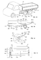
figure 1 est une vue en perspective d'un ensemble routier selon un premier mode de réalisation de l'invention, comprenant une remorque équipée d'une carrosserie en position accrochée sur un véhicule tracteur ; - la
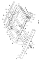
figure 2 est une vue en perspective de dessus du châssis de la remorque de l'ensemble routier de lafigure 1 , en l'absence de carrosserie ; - la
figure 3 est une autre vue en perspective de dessus du châssis de la remorque de lafigure 1 , avec des arrachés partiels au niveau de la partie centrale du châssis faisant apparaître le système de suspension ; - la
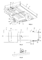
figure 4 est une vue en perspective de dessous de la remorque de lafigure 1 faisant apparaître l'espace libre compris sous sa partie centrale et entre ses supports de roues ; - la
figure 5 est une vue de dessus du véhicule tracteur de lafigure 1 , sur laquelle est illustré le positionnement du système de suspension et des roues de la remorque dans la position accrochée de la remorque - la
figure 6 est une vue en perspective des moyens d'accrochage du véhicule tracteur de lafigure 1 ; - la
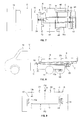
figure 7 est une vue de dessus de l'ensemble routier de lafigure 1 en l'absence de carrosserie sur la remorque ; - la
figure 8 est une vue schématique en coupe selon le plan longitudinal vertical du véhicule tracteur de l'ensemble routier de lafigure 1 faisant apparaître en hachuré les zones de débattements verticaux Z1 et longitudinaux Z2 de la remorque; - la
figure 9 est une vue schématique arrière de l'ensemble routier de lafigure 1 , illustrant le positionnement du châssis de la remorque par rapport au châssis du véhicule tracteur ; - la
figure 10 est une vue de dessus du châssis de la remorque de lafigure 3 , dont les longerons télescopiques ont été fixés longitudinalement en position pour s'adapter à un véhicule tracteur à châssis de grande longueur ; - la
figure 11 est une vue de coté d'un autre ensemble routier selon l'invention comprenant le châssis de remorque de lafigure 10 équipé d'une carrosserie, et un véhicule tracteur à châssis de grande longueur ; - la
figure 12 est une vue de dessus du châssis de la remorque de lafigure 3 , dont les longerons télescopiques ont été fixés longitudinalement en position pour s'adapter à un véhicule tracteur à châssis de petite longueur ; - la
figure 13 est une vue de côté d'un autre ensemble routier selon l'invention comprenant le châssis de remorque de lafigure 12 équipé d'une carrosserie, et un véhicule tracteur à châssis de petite longueur ; - la
figure 14 est une vue en perspective d'un ensemble routier selon un deuxième mode de réalisation de l'invention, comprenant une remorque carrossée équipée d'une suspension à lames de ressort en position accrochée sur un véhicule tracteur ; - la
figure 15 est une vue partielle de côté des châssis du véhicule tracteur et de la remorque de l'ensemble routier de lafigure 14 ; - la
figure 16 est une vue schématique en perspective d'un support de roue et d'une roue de la remorque de l'ensemble routier de lafigure 14 ; et, - la
figure 17 est une vue schématique en coupe selon un plan vertical transversal de l'ensemble routier de lafigure 14 .
- the
figure 1 is a perspective view of a road assembly according to a first embodiment of the invention, comprising a trailer equipped with a body in position hung on a towing vehicle; - the
figure 2 is a perspective view from above of the chassis of the trailer of the road assembly of thefigure 1 , in the absence of bodywork; - the
figure 3 is another perspective view from above of the trailer chassis of thefigure 1 , with partial tears at the central part of the chassis showing the suspension system; - the
figure 4 is a perspective view from below of the trailer of thefigure 1 showing the free space included under its central part and between its wheel supports; - the
figure 5 is a top view of the towing vehicle of thefigure 1 , on which is illustrated the positioning of the suspension system and the wheels of the trailer in the hooked position of the trailer - the
figure 6 is a perspective view of the attachment means of the towing vehicle of thefigure 1 ; - the
figure 7 is a top view of the road set of thefigure 1 in the absence of bodywork on the trailer; - the
figure 8 is a schematic sectional view along the vertical longitudinal plane of the tractor vehicle of the road assembly of thefigure 1 shading the zones Z1 vertical and Z2 longitudinal movements of the trailer; - the
figure 9 is a schematic rear view of the road set of thefigure 1 illustrating the positioning of the chassis of the trailer relative to the chassis of the towing vehicle; - the
figure 10 is a top view of the chassis of the trailer of thefigure 3 , whose telescopic beams were fixed longitudinally in position to fit a towing vehicle with a long chassis; - the
figure 11 is a side view of another road assembly according to the invention comprising the trailer chassis of thefigure 10 equipped with a body, and a towing vehicle with a long chassis; - the
figure 12 is a top view of the chassis of the trailer of thefigure 3 , of which the telescopic beams have been fixed longitudinally in position to fit a tractor vehicle with a short chassis; - the
figure 13 is a side view of another road assembly according to the invention comprising the trailer chassis of thefigure 12 equipped with a bodywork, and a tractor vehicle with a short chassis; - the
figure 14 is a perspective view of a road assembly according to a second embodiment of the invention, comprising a bodied trailer equipped with a spring leaf suspension in a hooked position on a towing vehicle; - the
figure 15 is a partial side view of the chassis of the towing vehicle and the trailer of the road assembly of thefigure 14 ; - the
figure 16 is a schematic perspective view of a wheel support and a wheel of the trailer of the road assembly of thefigure 14 ; and, - the
figure 17 is a schematic sectional view along a transverse vertical plane of the road assembly of thefigure 14 .
Les
En référence à la
En référence aux
Chaque roue 58 est montée sur un longeron support au moyen d'un bras oscillant 50 ou bras de suspension, monté pivotant par une extrémité sous la paroi inférieure du longeron, entre deux pattes verticales 51, autour d'un axe de rotation horizontal, et portant à son autre extrémité le moyeu 57 d'une roue. Les bras oscillants sont incurvés vers l'extérieur de manière à porter le moyeu et sa roue du côté extérieur de la paroi latérale extérieure 41a. Les bras oscillants sont de type tirés, ils s'étendent vers l'arrière depuis leur axe de rotation.Each
Chaque bras oscillant est solidaire en rotation d'un bras 52 auquel est monté articulée une première extrémité d'une biellette 53. Les secondes extrémités des biellettes sont montées articulées aux extrémités d'un dispositif élastique 54 disposé en partie arrière de la partie centrale. Les bras 52 passent par des ouvertures de la paroi inférieure 43 et s'étendent à l'intérieur des longerons support. Les biellettes disposées dans les longerons support sont articulées aux extrémités du dispositif élastique 54 monté entre les longerons support 40. A titre d'exemple, le dispositif élastique 54 est formé d'un essieu classique de remorque dit à profilé caoutchouc, comprenant un tube carré ou sensiblement triangulaire fixe, monté entre les longerons support, dans lequel est monté à 45° un petit tube carré ou sensiblement triangulaire, ainsi que quatre ou trois profilés caoutchouc. Les extrémités du petit tube carré portent des bras 55 munis d'axes transversaux 56 auxquels sont articulées les biellettes 53. Les bras oscillants 50, les bras 52, les biellettes 53 et le dispositif élastique forment le système de suspension 5 (
Le châssis comprend en outre une paire de longerons avant 61, 62 télescopiques et une paire de longerons arrière 63, 64 télescopiques. Les longerons avant sont fixés par des premiers moyens de fixation 65, par exemple des cavaliers en U, sur la traverse avant 31. Les deux longerons avant sont fixés symétriquement de part et d'autre du plan longitudinal vertical P2 (
Une traverse support avant 70 est fixée rigidement sur le dessus de la partie avant des longerons avant. La traverse support avant porte en extrémité des béquilles latérales 71, démontables, repliables ou escamotables, qui supportent le poids avant de la remorque lorsque celle-ci est dételée. La traverse support avant 70 porte également deux supports 72 étroits fixés rigidement sur la traverse avant, réglables transversalement lors du carrossage et destinés à recevoir la fixation des extrémités avant du faux-châssis de la carrosserie.A
Le châssis C peut être équipé de différents types de carrosserie, par exemple d'une benne 9, basculante ou non basculante, tel qu'illustré sur les
Les longerons télescopiques sont fixés à un entraxe tel que l'encombrement latéral extérieur des longerons, leurs moyens de fixation compris, soit inférieur à la distance séparant les faces intérieures des longerons 13 de châssis de véhicule utilitaire de type châssis cabine les plus étroits disponibles sur le marché, afin de permettre la fixation du faux châssis de la carrosserie, non pas sur les longerons du châssis de la remorque comme cela est réalisé de façon classique, mais sur les traverses avant et arrière qui supportent les longerons du châssis de la remorque. Grâce à cette disposition, les traverses du châssis de la remorque peuvent recevoir la fixation de différents faux châssis de carrosserie, quelles que soient leurs largeurs. Par ailleurs, la hauteur de chargement est plus basse car diminuée d'une valeur correspondant à la hauteur des longerons du châssis.The telescopic longitudinal members are fixed at a distance between them, such as the external lateral dimensions of the longitudinal members, and their fastening means. that is, less than the distance between the inner faces of the narrowest chassis chassis type utility vehicle frame rails 13 available on the market, in order to allow the attachment of the subframe of the body, not to the chassis side members. of the trailer as conventionally made, but on the front and rear sleepers that support the frame of the trailer frame. With this arrangement, the sleepers of the frame of the trailer can receive the fixing of different bodyshell chassis, regardless of their widths. In addition, the loading height is lower because less a value corresponding to the height of the frame rails.
Le timon coulissant 8 est disposé selon le plan longitudinal vertical P2 de la remorque. Le timon coulissant comprend une première partie fixe qui est solidaire du châssis de la remorque, à l'avant de celui-ci, et une partie mobile destiné à être accrochée à un véhicule tracteur pour l'utilisation de la remorque. En référence aux
Pour l'attelage de la remorque, le châssis du véhicule tracteur comprend des moyens d'accrochage formé ici d'une broche 21 montée sur une chape 22 et actionnable par un levier 23, connus en soi. Tel qu'illustré à la
L'ensemble routier comprend en outre un dispositif de guidage axial, tel que décrit dans les documents brevet précités, pour maintenir l'axe longitudinal médian A (
- lesdits seconds moyens de guidage comprennent deux seconds éléments de guidage, de préférence identiques, montés symétriquement sur le châssis de la remorque, de part et d'autre de son plan longitudinal vertical et en vis-à-vis, par exemple montés sur les parois latérales verticales intérieure 41b des longerons support ou constitués par lesdites parois latérales verticales,
- chaque second élément de guidage étant apte à venir sensiblement en contact par une surface active de contact avec une surface active de contact d'un premier élément de guidage dans un plan de contact sensiblement vertical qui est extérieur au châssis du véhicule tracteur et intérieur au châssis de la remorque.
- said second guide means comprise two second guide elements, preferably identical, mounted symmetrically on the frame of the trailer, on either side of its vertical longitudinal plane and facing each other, for example mounted on the walls; lateral vertical vertical 41b support rails or constituted by said vertical side walls,
- each second guide element being able to come into substantially contact with an active contact surface with an active contact surface of a first guide element in a plane substantially vertical contact which is external to the chassis of the towing vehicle and inside the frame of the trailer.
En position accrochée, tel qu'illustré aux
Les longerons support 40, intercalés entre les roues de la remorque 58 et les parties arrière du châssis du véhicule tracteur 10a, comprennent des parois latérales 41a, 41b minces très rigides afin de compenser l'étroitesse de l'espace disponible. Avantageusement, lesdites parois sont démontables et peuvent exister en plusieurs hauteurs, de façon à pouvoir ajuster, si nécessaire, la hauteur du châssis de la remorque, en fonction du choix de l'essieu ou des dimensions de roues, à la hauteur du châssis du véhicule tracteur.The support beams 40, interposed between the wheels of the
La
Les
Les
Le véhicule tracteur V"' comprend un châssis cabine 301 possédant un châssis 310, comprenant deux longerons 313, de section transversale en U, sur lesquels est notamment monté un essieu arrière portant des roues arrière 311, l'essieu arrière étant équipé d'un système de suspension à lames. Le système de suspension comprend au moins une lame de suspension 314 disposée longitudinalement le long de chaque longeron. Chaque longeron a une section transversale en U, avec une base disposée verticalement et des branches horizontales orientées vers l'intérieur. Chaque lame de suspension est fixée par ses extrémités à un longeron, au moyen de chapes 315 qui sont fixées sur le côté extérieur de la base d'un longeron, et auxquelles les extrémités de la lame sont assemblées de manière pivotante autour d'axes transversaux. Le corps central de l'essieu arrière porte à chaque extrémité le moyeu 316 d'une roue arrière 311, et est fixée sur la partie centrale de chaque lame de suspension 314. Le châssis présente une partie dite arrière 310a qui s'étend derrière les roues arrière 311.The towing vehicle V "'comprises a
La remorque R"' comprend un châssis C"' comportant une partie centrale 303 portant les deux roues 358 de la remorque. Cette partie centrale comprend deux longerons 334 portant deux supports de roue formés ici par les lames de suspension 340 longitudinales d'un système de suspension 305. Chaque roue 358 est montée à l'extrémité d'un essieu transversal 354 rigide dont l'axe du corps central 354a est situé plus bas que l'axe des roues, et l'essieu transversal est relié au châssis par les lames de suspension longitudinales fixées aux longerons de la partie centrale.The trailer R "'comprises a chassis C"' having a
En référence aux
Comme précédemment, le châssis C"' de la remorque R"' est équipé d'un timon coulissant portant en extrémité avant des moyens d'accrochage coopérant avec des moyens d'accrochage complémentaires du véhicule tracteur, et l'ensemble routier comprend un dispositif de guidage axial, pour maintenir l'axe longitudinal médian de la remorque sensiblement dans le plan longitudinal vertical du véhicule tracteur.As previously, the chassis C "'of the trailer R"' is equipped with a sliding drawbar bearing at the front end hooking means cooperating with complementary coupling means of the towing vehicle, and the road assembly comprises a device axial guide, for maintaining the median longitudinal axis of the trailer substantially in the vertical longitudinal plane of the towing vehicle.
Dans la position accrochée de la remorque, la partie centrale 303 de celle-ci, comprenant ses longerons 334 et les lames de suspension 340, vient à cheval sur la partie arrière 310a du châssis 310 du véhicule tracteur. Les lames de suspension s'étendent le long de la partie arrière 310a des longerons 313 du châssis du véhicule tracteur. Le corps central, situé sous la partie arrière 310a du châssis du véhicule tracteur, est disposé plus bas que l'axe des roues de façon à ne pas venir heurter la partie inférieure de la partie arrière 310a du châssis lors des mouvements de suspension.In the hooked position of the trailer, the
En variante, les lames de suspension précitées sont fixées par leur partie centrale aux longerons de la partie centrale du châssis de la remorque et s'étendent vers le bas depuis leur partie centrale. Les extrémités avant et arrière des lames de suspension portent des essieux tandem de type bogie. En position accrochée, l'essieu de la remorque le plus en avant vient sous le châssis du véhicule tracteur.Alternatively, the aforementioned suspension blades are fixed by their central portion to the longitudinal members of the central portion of the frame of the trailer and extend downwardly from their central portion. Front and rear ends of suspension blades carry axles tandem bogie type. In the hooked position, the axle of the most forward trailer comes under the chassis of the towing vehicle.
Bien que l'invention ait été décrite en liaison avec deux modes de réalisation particuliers, il est bien évident qu'elle n'y est nullement limitée et qu'elle comprend tous les équivalents techniques des moyens décrits ainsi que leurs combinaisons si celles-ci entrent dans le cadre de l'invention.Although the invention has been described in connection with two particular embodiments, it is obvious that it is not limited thereto and that it comprises all the technical equivalents of the means described and their combinations if they are within the scope of the invention.
Claims (15)
caractérisé en ce que
characterized in that
caractérisée en ce que
characterized in that
Priority Applications (1)
| Application Number | Priority Date | Filing Date | Title |
|---|---|---|---|
| PL10173122T PL2289773T3 (en) | 2009-08-27 | 2010-08-17 | Vehicle combination including a tractor vehicle, a trailer with a sliding drawbar and an axial guide device, and corresponding trailer |
Applications Claiming Priority (1)
| Application Number | Priority Date | Filing Date | Title |
|---|---|---|---|
| FR0955856A FR2949419B1 (en) | 2009-08-27 | 2009-08-27 | ROAD ASSEMBLY COMPRISING A TRACTOR VEHICLE, A SLIDING TIMON TRAILER AND AN AXIAL GUIDE DEVICE, AND CORRESPONDING TRAILER |
Publications (2)
| Publication Number | Publication Date |
|---|---|
| EP2289773A1 true EP2289773A1 (en) | 2011-03-02 |
| EP2289773B1 EP2289773B1 (en) | 2012-06-20 |
Family
ID=42026236
Family Applications (1)
| Application Number | Title | Priority Date | Filing Date |
|---|---|---|---|
| EP10173122A Active EP2289773B1 (en) | 2009-08-27 | 2010-08-17 | Vehicle combination including a tractor vehicle, a trailer with a sliding drawbar and an axial guide device, and corresponding trailer |
Country Status (5)
| Country | Link |
|---|---|
| EP (1) | EP2289773B1 (en) |
| DK (1) | DK2289773T3 (en) |
| ES (1) | ES2389888T3 (en) |
| FR (1) | FR2949419B1 (en) |
| PL (1) | PL2289773T3 (en) |
Cited By (2)
| Publication number | Priority date | Publication date | Assignee | Title |
|---|---|---|---|---|
| EP2556973A1 (en) | 2011-08-09 | 2013-02-13 | LG Développement | Road assembly with axial guidance system acting in front of the rear axle of towing vehicle |
| FR3037311A1 (en) * | 2015-06-09 | 2016-12-16 | Renault Sa | DEVICE FOR HANGING A TRAILER TO A TRACTOR VEHICLE AND ASSEMBLY FORMED BY THE COUPLING OF A TRACTOR VEHICLE AND A TRAILER COMPRISING SUCH A DEVICE |
Families Citing this family (6)
| Publication number | Priority date | Publication date | Assignee | Title |
|---|---|---|---|---|
| EP3379222B1 (en) | 2017-03-22 | 2020-12-30 | Methode Electronics Malta Ltd. | Magnetoelastic based sensor assembly |
| US11135882B2 (en) | 2018-02-27 | 2021-10-05 | Methode Electronics, Inc. | Towing systems and methods using magnetic field sensing |
| US10670479B2 (en) | 2018-02-27 | 2020-06-02 | Methode Electronics, Inc. | Towing systems and methods using magnetic field sensing |
| US11221262B2 (en) | 2018-02-27 | 2022-01-11 | Methode Electronics, Inc. | Towing systems and methods using magnetic field sensing |
| US11084342B2 (en) | 2018-02-27 | 2021-08-10 | Methode Electronics, Inc. | Towing systems and methods using magnetic field sensing |
| US11491832B2 (en) | 2018-02-27 | 2022-11-08 | Methode Electronics, Inc. | Towing systems and methods using magnetic field sensing |
Citations (4)
| Publication number | Priority date | Publication date | Assignee | Title |
|---|---|---|---|---|
| GB1300701A (en) * | 1970-04-21 | 1972-12-20 | Fiat Spa | Road transport vehicle |
| US4049289A (en) * | 1976-06-28 | 1977-09-20 | Deckrow Rodger E | Composite automotive vehicle, components thereof, and a method of constructing and using the same |
| EP1462280A1 (en) * | 2003-03-29 | 2004-09-29 | Schmitz Gotha Fahrzeugwerke GmbH | Trailer hitch bar adjustable in length |
| EP1598262A1 (en) | 2004-05-18 | 2005-11-23 | Kerklingh, Herman Karel | A tractor semi-trailer combination with detachable coupling means, and free rotation around a single rotation axis |
-
2009
- 2009-08-27 FR FR0955856A patent/FR2949419B1/en not_active Expired - Fee Related
-
2010
- 2010-08-17 PL PL10173122T patent/PL2289773T3/en unknown
- 2010-08-17 DK DK10173122.2T patent/DK2289773T3/en active
- 2010-08-17 EP EP10173122A patent/EP2289773B1/en active Active
- 2010-08-17 ES ES10173122T patent/ES2389888T3/en active Active
Patent Citations (4)
| Publication number | Priority date | Publication date | Assignee | Title |
|---|---|---|---|---|
| GB1300701A (en) * | 1970-04-21 | 1972-12-20 | Fiat Spa | Road transport vehicle |
| US4049289A (en) * | 1976-06-28 | 1977-09-20 | Deckrow Rodger E | Composite automotive vehicle, components thereof, and a method of constructing and using the same |
| EP1462280A1 (en) * | 2003-03-29 | 2004-09-29 | Schmitz Gotha Fahrzeugwerke GmbH | Trailer hitch bar adjustable in length |
| EP1598262A1 (en) | 2004-05-18 | 2005-11-23 | Kerklingh, Herman Karel | A tractor semi-trailer combination with detachable coupling means, and free rotation around a single rotation axis |
Cited By (2)
| Publication number | Priority date | Publication date | Assignee | Title |
|---|---|---|---|---|
| EP2556973A1 (en) | 2011-08-09 | 2013-02-13 | LG Développement | Road assembly with axial guidance system acting in front of the rear axle of towing vehicle |
| FR3037311A1 (en) * | 2015-06-09 | 2016-12-16 | Renault Sa | DEVICE FOR HANGING A TRAILER TO A TRACTOR VEHICLE AND ASSEMBLY FORMED BY THE COUPLING OF A TRACTOR VEHICLE AND A TRAILER COMPRISING SUCH A DEVICE |
Also Published As
| Publication number | Publication date |
|---|---|
| PL2289773T3 (en) | 2012-11-30 |
| DK2289773T3 (en) | 2012-09-24 |
| EP2289773B1 (en) | 2012-06-20 |
| ES2389888T3 (en) | 2012-11-02 |
| FR2949419B1 (en) | 2011-09-09 |
| FR2949419A1 (en) | 2011-03-04 |
Similar Documents
| Publication | Publication Date | Title |
|---|---|---|
| EP2289773B1 (en) | Vehicle combination including a tractor vehicle, a trailer with a sliding drawbar and an axial guide device, and corresponding trailer | |
| EP2151373B1 (en) | Road combination | |
| EP0139561B1 (en) | Trailer which may be tipped into various positions by being pushed backwards | |
| EP2316714B1 (en) | Vehicle combination comprising a tractor, a trailer with a sliding drawbar and an axial guiding device having a retractable pivoting arm | |
| EP0505470A1 (en) | Trailer with combined towing and centering means. | |
| EP2032417A2 (en) | Trolley comprising means for limiting the turning of the wheels | |
| FR2880861A1 (en) | Gooseneck chassis for use with tractor, has rollers maintaining main chassis and body subframe horizontally, when containers are loaded, where rollers roll on longitudinal rails fixed on body subframe | |
| FR2764770A1 (en) | ROUND BALE PRESSES FOR AGRICULTURAL HARVESTS PROVIDED WITH DAMPING AND / OR SUSPENSION ELEMENTS ALLOWING THEIR MOVEMENT ON THE HIGH SPEED ROAD | |
| EP2289774B1 (en) | Anti-knifing axial guiding device for a road train comprising a tractor vehicle and a trailer having a sliding drawbar | |
| BE1001491A3 (en) | COUPLING DEVICE TO BE MOUNTED ON A RAILWAY BOGIE to hitch WAGON TRANSPORT BIMODAL PRE-DONE TO APPROPRIATE MANNER. | |
| EP2505429B1 (en) | Method for adjusting the wheelbase of a wheel-mounted assembly comprising at least two handling devices for containers | |
| FR2702441A1 (en) | Intermediate support structure for tipper platform of a utility vehicle | |
| EP2786648B1 (en) | Improved coupling device | |
| FR2525853A1 (en) | HITCH POST FOR THE THREE-POINT LIFT DEVICE OF A TRACTOR | |
| EP4257467A1 (en) | Assembly comprising a vehicle such as a cycle comprising a rear axle having an axle-free stabiliser system, and a removable load-bearing device | |
| FR2948065A1 (en) | Motor vehicle e.g. lorry, for transporting e.g. people, has bar located at back of rear wheels, and coupling system comprising two parts that are connected with each other, where one of parts is mounted on trailer | |
| FR3037308A1 (en) | TRAILER FOR REACHING A TRACTOR VEHICLE AND ASSEMBLY COMPRISING SUCH A TRAILER | |
| WO2016198768A1 (en) | Semi-trailer intended to be coupled to a towing vehicle, and coupled assembly comprising such a trailer | |
| EP2420397B1 (en) | Coupling device for coupling a trailer to a vehicle | |
| FR2882621A1 (en) | Windrower for tractor, has detachable draw bar comprising complimentary device connected to connection device for permitting installation of windrower on hitching device hitched to front or rear of tractor, in three points | |
| FR3113027A1 (en) | Undercarriage for amphibious vehicle | |
| FR2525854A1 (en) | Triple roller for towing by tractor - uses two retractable wing rollers leading centre roller behind chassis on retractable road wheels | |
| FR2663812A3 (en) | Agricultural implement comprising a hitching beam which can be brought into a position in which it can pivot with respect to the implement | |
| EP0554229A1 (en) | Semi-trailer | |
| FR2509248A1 (en) | Luggage trailer for vehicle - has frame and floor formed integrally from steel sheet |
Legal Events
| Date | Code | Title | Description |
|---|---|---|---|
| PUAI | Public reference made under article 153(3) epc to a published international application that has entered the european phase |
Free format text: ORIGINAL CODE: 0009012 |
|
| AK | Designated contracting states |
Kind code of ref document: A1 Designated state(s): AL AT BE BG CH CY CZ DE DK EE ES FI FR GB GR HR HU IE IS IT LI LT LU LV MC MK MT NL NO PL PT RO SE SI SK SM TR |
|
| AX | Request for extension of the european patent |
Extension state: BA ME RS |
|
| 17P | Request for examination filed |
Effective date: 20110803 |
|
| GRAP | Despatch of communication of intention to grant a patent |
Free format text: ORIGINAL CODE: EPIDOSNIGR1 |
|
| RIC1 | Information provided on ipc code assigned before grant |
Ipc: B62D 63/06 20060101ALI20111219BHEP Ipc: B60D 1/30 20060101ALI20111219BHEP Ipc: B60D 1/155 20060101ALI20111219BHEP Ipc: B62D 53/04 20060101AFI20111219BHEP |
|
| GRAS | Grant fee paid |
Free format text: ORIGINAL CODE: EPIDOSNIGR3 |
|
| GRAA | (expected) grant |
Free format text: ORIGINAL CODE: 0009210 |
|
| AK | Designated contracting states |
Kind code of ref document: B1 Designated state(s): AL AT BE BG CH CY CZ DE DK EE ES FI FR GB GR HR HU IE IS IT LI LT LU LV MC MK MT NL NO PL PT RO SE SI SK SM TR |
|
| REG | Reference to a national code |
Ref country code: GB Ref legal event code: FG4D Free format text: NOT ENGLISH |
|
| RAP2 | Party data changed (patent owner data changed or rights of a patent transferred) |
Owner name: LG DEVELOPPEMENT |
|
| RIN2 | Information on inventor provided after grant (corrected) |
Inventor name: LG DEVELOPPEMENT |
|
| REG | Reference to a national code |
Ref country code: CH Ref legal event code: EP |
|
| REG | Reference to a national code |
Ref country code: AT Ref legal event code: REF Ref document number: 562906 Country of ref document: AT Kind code of ref document: T Effective date: 20120715 |
|
| REG | Reference to a national code |
Ref country code: IE Ref legal event code: FG4D Free format text: LANGUAGE OF EP DOCUMENT: FRENCH |
|
| 111L | Licence recorded |
Designated state(s): AL AT BE BG CH CY CZ DE DK EE ES FI FR GB GR HR HU IE IS IT LT LU LV MC MK MT NL NO PL PT RO SE SI SK SM TR Free format text: EXCLUSIVE LICENSE Name of requester: MAXICARGO, FR Effective date: 20120615 |
|
| REG | Reference to a national code |
Ref country code: DE Ref legal event code: R096 Ref document number: 602010001937 Country of ref document: DE Effective date: 20120816 |
|
| RIN2 | Information on inventor provided after grant (corrected) |
Inventor name: LE GOFF, PHILIPPE |
|
| REG | Reference to a national code |
Ref country code: CH Ref legal event code: NV Representative=s name: NOVAGRAAF INTERNATIONAL SA |
|
| REG | Reference to a national code |
Ref country code: AT Ref legal event code: HC Ref document number: 562906 Country of ref document: AT Kind code of ref document: T Owner name: LG DEVELOPPEMENT, FR Effective date: 20120719 |
|
| REG | Reference to a national code |
Ref country code: DK Ref legal event code: T3 |
|
| REG | Reference to a national code |
Ref country code: SE Ref legal event code: TRGR |
|
| REG | Reference to a national code |
Ref country code: NL Ref legal event code: T3 |
|
| PG25 | Lapsed in a contracting state [announced via postgrant information from national office to epo] |
Ref country code: FI Free format text: LAPSE BECAUSE OF FAILURE TO SUBMIT A TRANSLATION OF THE DESCRIPTION OR TO PAY THE FEE WITHIN THE PRESCRIBED TIME-LIMIT Effective date: 20120620 Ref country code: NO Free format text: LAPSE BECAUSE OF FAILURE TO SUBMIT A TRANSLATION OF THE DESCRIPTION OR TO PAY THE FEE WITHIN THE PRESCRIBED TIME-LIMIT Effective date: 20120920 Ref country code: LT Free format text: LAPSE BECAUSE OF FAILURE TO SUBMIT A TRANSLATION OF THE DESCRIPTION OR TO PAY THE FEE WITHIN THE PRESCRIBED TIME-LIMIT Effective date: 20120620 |
|
| REG | Reference to a national code |
Ref country code: ES Ref legal event code: FG2A Ref document number: 2389888 Country of ref document: ES Kind code of ref document: T3 Effective date: 20121102 |
|
| REG | Reference to a national code |
Ref country code: AT Ref legal event code: MK05 Ref document number: 562906 Country of ref document: AT Kind code of ref document: T Effective date: 20120620 |
|
| REG | Reference to a national code |
Ref country code: LT Ref legal event code: MG4D Effective date: 20120620 |
|
| PG25 | Lapsed in a contracting state [announced via postgrant information from national office to epo] |
Ref country code: GR Free format text: LAPSE BECAUSE OF FAILURE TO SUBMIT A TRANSLATION OF THE DESCRIPTION OR TO PAY THE FEE WITHIN THE PRESCRIBED TIME-LIMIT Effective date: 20120921 Ref country code: HR Free format text: LAPSE BECAUSE OF FAILURE TO SUBMIT A TRANSLATION OF THE DESCRIPTION OR TO PAY THE FEE WITHIN THE PRESCRIBED TIME-LIMIT Effective date: 20120620 Ref country code: SI Free format text: LAPSE BECAUSE OF FAILURE TO SUBMIT A TRANSLATION OF THE DESCRIPTION OR TO PAY THE FEE WITHIN THE PRESCRIBED TIME-LIMIT Effective date: 20120620 Ref country code: LV Free format text: LAPSE BECAUSE OF FAILURE TO SUBMIT A TRANSLATION OF THE DESCRIPTION OR TO PAY THE FEE WITHIN THE PRESCRIBED TIME-LIMIT Effective date: 20120620 |
|
| REG | Reference to a national code |
Ref country code: PL Ref legal event code: T3 |
|
| PG25 | Lapsed in a contracting state [announced via postgrant information from national office to epo] |
Ref country code: IS Free format text: LAPSE BECAUSE OF FAILURE TO SUBMIT A TRANSLATION OF THE DESCRIPTION OR TO PAY THE FEE WITHIN THE PRESCRIBED TIME-LIMIT Effective date: 20121020 Ref country code: AT Free format text: LAPSE BECAUSE OF FAILURE TO SUBMIT A TRANSLATION OF THE DESCRIPTION OR TO PAY THE FEE WITHIN THE PRESCRIBED TIME-LIMIT Effective date: 20120620 Ref country code: SK Free format text: LAPSE BECAUSE OF FAILURE TO SUBMIT A TRANSLATION OF THE DESCRIPTION OR TO PAY THE FEE WITHIN THE PRESCRIBED TIME-LIMIT Effective date: 20120620 Ref country code: EE Free format text: LAPSE BECAUSE OF FAILURE TO SUBMIT A TRANSLATION OF THE DESCRIPTION OR TO PAY THE FEE WITHIN THE PRESCRIBED TIME-LIMIT Effective date: 20120620 Ref country code: CY Free format text: LAPSE BECAUSE OF FAILURE TO SUBMIT A TRANSLATION OF THE DESCRIPTION OR TO PAY THE FEE WITHIN THE PRESCRIBED TIME-LIMIT Effective date: 20120620 Ref country code: RO Free format text: LAPSE BECAUSE OF FAILURE TO SUBMIT A TRANSLATION OF THE DESCRIPTION OR TO PAY THE FEE WITHIN THE PRESCRIBED TIME-LIMIT Effective date: 20120620 Ref country code: CZ Free format text: LAPSE BECAUSE OF FAILURE TO SUBMIT A TRANSLATION OF THE DESCRIPTION OR TO PAY THE FEE WITHIN THE PRESCRIBED TIME-LIMIT Effective date: 20120620 |
|
| BERE | Be: lapsed |
Owner name: LG DEVELOPPEMENT Effective date: 20120831 |
|
| PG25 | Lapsed in a contracting state [announced via postgrant information from national office to epo] |
Ref country code: PT Free format text: LAPSE BECAUSE OF FAILURE TO SUBMIT A TRANSLATION OF THE DESCRIPTION OR TO PAY THE FEE WITHIN THE PRESCRIBED TIME-LIMIT Effective date: 20121022 |
|
| PG25 | Lapsed in a contracting state [announced via postgrant information from national office to epo] |
Ref country code: MC Free format text: LAPSE BECAUSE OF NON-PAYMENT OF DUE FEES Effective date: 20120831 |
|
| PLBE | No opposition filed within time limit |
Free format text: ORIGINAL CODE: 0009261 |
|
| STAA | Information on the status of an ep patent application or granted ep patent |
Free format text: STATUS: NO OPPOSITION FILED WITHIN TIME LIMIT |
|
| REG | Reference to a national code |
Ref country code: IE Ref legal event code: MM4A |
|
| 26N | No opposition filed |
Effective date: 20130321 |
|
| PG25 | Lapsed in a contracting state [announced via postgrant information from national office to epo] |
Ref country code: BE Free format text: LAPSE BECAUSE OF NON-PAYMENT OF DUE FEES Effective date: 20120831 |
|
| REG | Reference to a national code |
Ref country code: DE Ref legal event code: R097 Ref document number: 602010001937 Country of ref document: DE Effective date: 20130321 |
|
| PG25 | Lapsed in a contracting state [announced via postgrant information from national office to epo] |
Ref country code: IE Free format text: LAPSE BECAUSE OF NON-PAYMENT OF DUE FEES Effective date: 20120817 Ref country code: BG Free format text: LAPSE BECAUSE OF FAILURE TO SUBMIT A TRANSLATION OF THE DESCRIPTION OR TO PAY THE FEE WITHIN THE PRESCRIBED TIME-LIMIT Effective date: 20120920 |
|
| PG25 | Lapsed in a contracting state [announced via postgrant information from national office to epo] |
Ref country code: MT Free format text: LAPSE BECAUSE OF FAILURE TO SUBMIT A TRANSLATION OF THE DESCRIPTION OR TO PAY THE FEE WITHIN THE PRESCRIBED TIME-LIMIT Effective date: 20120620 Ref country code: AL Free format text: LAPSE BECAUSE OF FAILURE TO SUBMIT A TRANSLATION OF THE DESCRIPTION OR TO PAY THE FEE WITHIN THE PRESCRIBED TIME-LIMIT Effective date: 20120620 |
|
| PG25 | Lapsed in a contracting state [announced via postgrant information from national office to epo] |
Ref country code: TR Free format text: LAPSE BECAUSE OF FAILURE TO SUBMIT A TRANSLATION OF THE DESCRIPTION OR TO PAY THE FEE WITHIN THE PRESCRIBED TIME-LIMIT Effective date: 20120620 |
|
| PG25 | Lapsed in a contracting state [announced via postgrant information from national office to epo] |
Ref country code: SM Free format text: LAPSE BECAUSE OF FAILURE TO SUBMIT A TRANSLATION OF THE DESCRIPTION OR TO PAY THE FEE WITHIN THE PRESCRIBED TIME-LIMIT Effective date: 20120620 Ref country code: LU Free format text: LAPSE BECAUSE OF NON-PAYMENT OF DUE FEES Effective date: 20120817 |
|
| PG25 | Lapsed in a contracting state [announced via postgrant information from national office to epo] |
Ref country code: HU Free format text: LAPSE BECAUSE OF FAILURE TO SUBMIT A TRANSLATION OF THE DESCRIPTION OR TO PAY THE FEE WITHIN THE PRESCRIBED TIME-LIMIT Effective date: 20100817 |
|
| PG25 | Lapsed in a contracting state [announced via postgrant information from national office to epo] |
Ref country code: MK Free format text: LAPSE BECAUSE OF FAILURE TO SUBMIT A TRANSLATION OF THE DESCRIPTION OR TO PAY THE FEE WITHIN THE PRESCRIBED TIME-LIMIT Effective date: 20120620 |
|
| REG | Reference to a national code |
Ref country code: FR Ref legal event code: PLFP Year of fee payment: 7 |
|
| REG | Reference to a national code |
Ref country code: FR Ref legal event code: PLFP Year of fee payment: 8 |
|
| REG | Reference to a national code |
Ref country code: FR Ref legal event code: PLFP Year of fee payment: 9 |
|
| P01 | Opt-out of the competence of the unified patent court (upc) registered |
Effective date: 20230527 |
|
| PGFP | Annual fee paid to national office [announced via postgrant information from national office to epo] |
Ref country code: NL Payment date: 20230823 Year of fee payment: 14 |
|
| PGFP | Annual fee paid to national office [announced via postgrant information from national office to epo] |
Ref country code: IT Payment date: 20230831 Year of fee payment: 14 Ref country code: GB Payment date: 20230824 Year of fee payment: 14 Ref country code: ES Payment date: 20230918 Year of fee payment: 14 Ref country code: CH Payment date: 20230902 Year of fee payment: 14 |
|
| PGFP | Annual fee paid to national office [announced via postgrant information from national office to epo] |
Ref country code: SE Payment date: 20230823 Year of fee payment: 14 Ref country code: PL Payment date: 20230807 Year of fee payment: 14 Ref country code: FR Payment date: 20230822 Year of fee payment: 14 Ref country code: DK Payment date: 20230823 Year of fee payment: 14 Ref country code: DE Payment date: 20230822 Year of fee payment: 14 |