EP2289608A2 - System und Verfahren zum Schutz eines SCR-Katalysators vor großen Aschepartikeln - Google Patents
System und Verfahren zum Schutz eines SCR-Katalysators vor großen Aschepartikeln Download PDFInfo
- Publication number
- EP2289608A2 EP2289608A2 EP10173906A EP10173906A EP2289608A2 EP 2289608 A2 EP2289608 A2 EP 2289608A2 EP 10173906 A EP10173906 A EP 10173906A EP 10173906 A EP10173906 A EP 10173906A EP 2289608 A2 EP2289608 A2 EP 2289608A2
- Authority
- EP
- European Patent Office
- Prior art keywords
- flue gas
- large particle
- scr
- particle ash
- designed
- Prior art date
- Legal status (The legal status is an assumption and is not a legal conclusion. Google has not performed a legal analysis and makes no representation as to the accuracy of the status listed.)
- Granted
Links
Images
Classifications
-
- F—MECHANICAL ENGINEERING; LIGHTING; HEATING; WEAPONS; BLASTING
- F23—COMBUSTION APPARATUS; COMBUSTION PROCESSES
- F23J—REMOVAL OR TREATMENT OF COMBUSTION PRODUCTS OR COMBUSTION RESIDUES; FLUES
- F23J15/00—Arrangements of devices for treating smoke or fumes
- F23J15/02—Arrangements of devices for treating smoke or fumes of purifiers, e.g. for removing noxious material
-
- B—PERFORMING OPERATIONS; TRANSPORTING
- B01—PHYSICAL OR CHEMICAL PROCESSES OR APPARATUS IN GENERAL
- B01D—SEPARATION
- B01D51/00—Auxiliary pretreatment of gases or vapours to be cleaned
- B01D51/10—Conditioning the gas to be cleaned
-
- B—PERFORMING OPERATIONS; TRANSPORTING
- B01—PHYSICAL OR CHEMICAL PROCESSES OR APPARATUS IN GENERAL
- B01D—SEPARATION
- B01D2258/00—Sources of waste gases
- B01D2258/02—Other waste gases
- B01D2258/0283—Flue gases
-
- B—PERFORMING OPERATIONS; TRANSPORTING
- B01—PHYSICAL OR CHEMICAL PROCESSES OR APPARATUS IN GENERAL
- B01D—SEPARATION
- B01D53/00—Separation of gases or vapours; Recovering vapours of volatile solvents from gases; Chemical or biological purification of waste gases, e.g. engine exhaust gases, smoke, fumes, flue gases, aerosols
- B01D53/34—Chemical or biological purification of waste gases
- B01D53/74—General processes for purification of waste gases; Apparatus or devices specially adapted therefor
- B01D53/86—Catalytic processes
- B01D53/8621—Removing nitrogen compounds
- B01D53/8625—Nitrogen oxides
- B01D53/8631—Processes characterised by a specific device
-
- F—MECHANICAL ENGINEERING; LIGHTING; HEATING; WEAPONS; BLASTING
- F23—COMBUSTION APPARATUS; COMBUSTION PROCESSES
- F23J—REMOVAL OR TREATMENT OF COMBUSTION PRODUCTS OR COMBUSTION RESIDUES; FLUES
- F23J2217/00—Intercepting solids
- F23J2217/30—Intercepting solids by screens
-
- F—MECHANICAL ENGINEERING; LIGHTING; HEATING; WEAPONS; BLASTING
- F23—COMBUSTION APPARATUS; COMBUSTION PROCESSES
- F23J—REMOVAL OR TREATMENT OF COMBUSTION PRODUCTS OR COMBUSTION RESIDUES; FLUES
- F23J2219/00—Treatment devices
- F23J2219/10—Catalytic reduction devices
-
- Y—GENERAL TAGGING OF NEW TECHNOLOGICAL DEVELOPMENTS; GENERAL TAGGING OF CROSS-SECTIONAL TECHNOLOGIES SPANNING OVER SEVERAL SECTIONS OF THE IPC; TECHNICAL SUBJECTS COVERED BY FORMER USPC CROSS-REFERENCE ART COLLECTIONS [XRACs] AND DIGESTS
- Y02—TECHNOLOGIES OR APPLICATIONS FOR MITIGATION OR ADAPTATION AGAINST CLIMATE CHANGE
- Y02E—REDUCTION OF GREENHOUSE GAS [GHG] EMISSIONS, RELATED TO ENERGY GENERATION, TRANSMISSION OR DISTRIBUTION
- Y02E50/00—Technologies for the production of fuel of non-fossil origin
- Y02E50/10—Biofuels, e.g. bio-diesel
Definitions
- the present invention relates generally to the field of emission control equipment for boilers, heaters, kilns, or other flue gas-, or combustion gas-, generating devices (e.g., those located at power plants, processing plants, etc.) and, in particular but not exclusively to a new and useful method and apparatus for preventing the plugging, blockage and/or contamination of an SCR catalyst.
- the method and apparatus of the present invention is designed to protect an SCR catalyst from plugging and/or blockage from large particle ash that may be generated during combustion.
- NO x refers to the cumulative emissions of nitric oxide (NO), nitrogen dioxide (NO 2 ) and trace quantities of other nitrogen oxide species generated during combustion. Combustion of any fossil fuel generates some level of NO x due to high temperatures and the availability of oxygen and nitrogen from both the air and fuel. NO x emissions may be controlled using low NO x combustion technology and post-combustion techniques.
- One such post-combustion technique is selective catalytic reduction using an apparatus generally referred to as a selective catalytic reactor or simply as an SCR.
- SCR technology is used worldwide to control NO x emissions from combustion sources. This technology has been used widely in Japan for NO x control from utility boilers since the late 1970's, in Germany since the late 1980's, and in the US since the 1990's.
- the function of the SCR system is to react NO x with ammonia (NH 3 ) and oxygen to form molecular nitrogen and water.
- Industrial scale SCRs have been designed to operate principally in the temperature range of 500°F to 900°F, but most often in the range of 550°F to 750°F. SCRs are typically designed to meet a specified NO x reduction efficiency at a maximum allowable ammonia slip. Ammonia slip is the concentration, expressed in parts per million by volume, of unreacted ammonia exiting the SCR.
- ammonia reacts with NO x according to the following stoichiometric reactions (a) to (c): 4NO + 4NH 3 + O 2 ⁇ 4N 2 + 6H 2 O (a) 12NO 2 + 12NH 3 ⁇ 12N 2 + 18H 2 O + 3O 2 (b) 2NO 2 + 4NH 3 + O 2 ⁇ 3N2 + 6H 2 O (c).
- Suitable catalysts are discussed in, for example, United States Patent Nos. 5,540,897 ; 5,567,394 ; and 5,585,081 to Chu et al ., all of which are hereby incorporated by reference as though fully set forth herein. Catalyst formulations generally fall into one of three categories: base metal, zeolite and precious metal.
- Base metal catalysts use titanium oxide with small amounts of vanadium, molybdenum, tungsten or a combination of several other active chemical agents.
- the base metal catalysts are selective and operate in the specified temperature range.
- the major drawback of the base metal catalyst is its potential to oxidize SO 2 to SO 3 ; the degree of oxidation varies based on catalyst chemical formulation.
- the quantities of SO 3 which are formed can react with the ammonia carryover to form various ammonium-sulfate salts.
- Zeolite catalysts are aluminosilicate materials which function similarly to base metal catalysts.
- One potential advantage of zeolite catalysts is their higher operating temperature of about 970°F (521 °C). These catalysts can also oxidize SO 2 to SO 3 and must be carefully matched to the flue gas conditions.
- Precious metal catalysts are generally manufactured from platinum and rhodium. Precious metal catalysts also require careful consideration of flue gas constituents and operating temperatures. While effective in reducing NO x , these catalysts can also act as oxidizing catalysts, converting CO to CO 2 under proper temperature conditions. However, SO 2 oxidation to SO 3 and high material costs often make precious metal catalysts less attractive.
- SCR catalysts undergo plugging and/or poisoning when they become contaminated by various compounds including, but not limited to, ash from the combustion process (in particular coal ash).
- ash from the combustion process in particular coal ash.
- One common source of plugging in SCRs is large particle ash (typically defined as any ash that has a particle size large enough to lodge in the catalyst passages, pores, or honeycomb structure present in the SCR catalyst blocks).
- the present invention relates generally to the field of emission control equipment for boilers, heaters, kilns, or other flue gas-, or combustion gas-, generating devices (e.g., those located at power plants, processing plants, etc.) and, in particular to a new and useful method and apparatus for preventing the plugging, blockage and/or contamination of an SCR catalyst.
- the method and apparatus of the present invention is designed to protect an SCR catalyst from plugging and/or blockage from large particle ash that may be generated during combustion.
- a system for increasing the active life of an SCR catalyst comprising: (i) at least one first flue gas conduit designed to transport flue gas from a combustion zone to an SCR; (ii) at least one SCR positioned between the at least one first flue gas conduit and at least one second flue gas conduit, wherein the at least one second flue gas conduit is designed to transport flue gas from the SCR to additional downstream systems or environmental controls; (iii) at least one large particle ash screen positioned in the at least one first flue conduit so as to enable the collection of at least about 50 percent of any large particle ash present in the flue gas prior to the entry of the flue gas into the at least one SCR; and (iv) at least one rotary valve positioned to be in working communication with the large particle ash screen, wherein the at least one rotary valve is designed to collect any large particle ash captured by the at least one large particle ash screen and supply such large particle ash to the at least one second flue
- a system for increasing the active life of an SCR catalyst comprising: (A) at least one first flue gas conduit designed to transport flue gas from a combustion zone to an SCR, the at least one first flue gas conduit being designed to permit the flue gas to flow at a first flow velocity; (B) at least one second flue gas conduit that is in operative communication with the at least one first flue gas conduit, wherein the at least one second flue gas conduit is designed to transport flue gas from the at least one first flue gas conduit to an SCR, the at least one second flue gas conduit being designed to permit the flue gas to flow at a second flow velocity, and the second flow velocity is at least 10 percent less than the first flow velocity; (C) at least one third flue gas conduit designed to transport flue gas from the SCR to additional downstream systems or environmental controls; and (D) at least one rotary valve positioned to be in working communication with the at least one second flue gas conduit, wherein the at least one rotary valve is designed to
- a method for increasing the active life of an SCR catalyst comprising the steps of: (a) providing at least one large particle ash collection means designed to collect large particle ash in a flue gas stream upstream of the entry of the flue gas into an SCR; and (b) collecting the large particle ash in the at least one large particle ash collection means so as to remove at least about 50 percent of the large particle ash from the flue gas stream prior to entry of the flue gas stream into the SCR; and (c) supplying the collected large particle ash to a point in the flue gas stream downstream of the SCR.
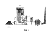
- Fig. 1 is a schematic representation of a typical fossil fuel burning facility, designed and initially provided with an SCR system;
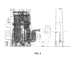
- Fig. 2 is a schematic representation of another typical fossil fuel burning facility which was not designed or initially provided with an SCR system;
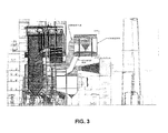
- Fig. 3 is a schematic representation of the fossil fuel burning facility of Fig. 2 , to which SCR equipment in accordance with the present disclosure has been added;
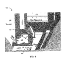
- Fig. 4 is a close-up, perspective view illustrating the arrangement of the flues from the boiler and the lower outlet portion of the SCR of Fig. 3 , in accordance with one embodiment;
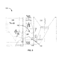
- Fig. 5 is a side view of the arrangement of the flues from the boiler and the lower outlet portion of the SCR of Fig. 4 , in accordance with one embodiment
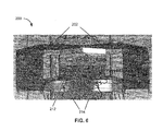
- Fig. 6 is a cross-sectional view of the arrangement of the flues from the boiler and the lower outlet portion of the SCR of Fig. 4 , viewed in the direction of arrows 6 - 6 of Fig. 3 .
- an ammoniacal compound is a term meant to include compounds such as urea, ammonium sulfate, cyanuric acid, and organic amines as well as ammonia (NH 3 ). These compounds could be used as reducing agents in addition to ammonia, but as mentioned above, ammonia is frequently selected for economic reasons.
- Some non-ammoniacal compounds such as carbon monoxide or methane can be used as well, but with a possible reduction in effectiveness.
- the present discussion is provided in relation to a boiler, or a fossil fuel boiler, the invention is not limited solely thereto. Instead, the present invention can be applied to any combustion source that generates NO x regardless of whether such a combustion source is utilized in conjunction with a boiler, or a steam generator.
- the present invention could be used in combination with a kiln, a heater, or any other type of combustion process that generates, in whole or in part, a flue gas or combustion gas containing NO x . Accordingly, the description below is to be construed as merely by way of example.
- the present invention can be applied to any SCR regardless of the type of catalyst that is utilized therein. As such, the present invention is not limited to any one type of SCR catalyst, but rather is broadly applicable to a wide range of SCR catalyst systems. Suitable catalyst systems include, but are not limited to, honeycomb, corrugated and plate-type catalysts.
- One embodiment of the present disclosure is directed to reducing the rate of SCR catalyst deactivation on Powder River Basin (PRB) coal combustion units.
- PRB Powder River Basin
- PRB Powder River Basin
- PRB coal is suspected to cause plugging, blockage and/or contamination of the catalyst passages, pores, or honeycomb structure present in the SCR catalyst blocks due to the presence of LPA which can be considered to be, in a non-limiting manner, popcorn ash.
- LPA is defined as ash having a mean particle size of at least about 4 mm, or even at least about 6 mm.
- LPA has any type of geometry including, but not limited to, irregular geometries, spherical geometries, oblong geometries, ellipsoidal geometries, or any combination of two or more thereof.
- LPA is defined as any ash that is larger than the catalyst passages, pores, or honeycomb structure present in the SCR catalyst blocks.
- the size of the LPA only has to be sufficient to cause plugging, blockage and/or contamination of the catalyst in the SCR.
- the present disclosure relates to a system and method to prevent plugging, blockage and/or contamination of the catalyst passages, pores, or honeycomb structure present in the SCR catalyst blocks due to the presence of LPA.
- the present disclosure addresses the aforementioned goal by the addition of at least one LPA screen and at least one rotary valve located at a position in the flue conduit downstream of the boiler but upstream of the SCR designed to remove at least about 50 percent of the LPA present in the flue gas stream.
- the present disclosure provides for removal of at least about 75 percent, at least about 85 percent, at least about 95 percent, or even at least about 99 percent of the LPA in the flue gas stream.
- individual range limits can be combined to form new and/or undisclosed ranges.
- Fig. 1 is an illustration of a typical power plant that utilizes coal as a combustion source, and which was designed and initially provided with an SCR system.
- a typical power plant includes a SCR located between a boiler portion of the power plant and a spray dry absorber (SDA).
- SDA spray dry absorber
- the SDA is used to remove sulfur oxides from the flue gas produced during the combustion process in the boiler portion.
- Fig. 2 which was not designed or initially provided with an SCR system, the flue gases from the boiler are conveyed through at least one flue to an air heater (in Fig.
- a system 100 of comprises at least one LPA screen 102 and at least one rotary valve 104 that are positioned along a flue conduit 106 downstream of the boiler 108 but upstream of the SCR reactor or SCR 110 so as to remove at least about 50 percent of the LPA present in the flue gas stream.
- the SCR unit 110 and an SCR outlet flue 112 therefrom are positioned in such a manner that the LPA collected from the flue gas prior to entry of the flue gas into the SCR 110 can be diverted and supplied to the SCR outlet flue 112.
- LPA screen 102 is provided at any suitable incline so as to cause LPA impacting LPA screen 102 to fall toward the at least one rotary valve 104. Additionally, LPA screen 102 is formed across the entire cross-section of flue conduit 106 so that any LPA present in the flue gas stream contained in conduit 106 is caused to attempt to "pass through" LPA screen 102.
- each conduit 106 has a LPA screen 102 and at least one rotary valve 104 as described above.
- each rotary valve is connected to a hopper designed to funnel LPA to a respective rotary valve.
- the SCR outlet flue, or flues, 112 is/are designed to transport the SCR-treated flue gas and "added" LPA to additional downstream systems and/or environmental controls (e.g., an air heater, an SDA, or a baghouse, precipitator or other particle control device).
- the at least one LPA screen 102 can be eliminated from the system in the instance where the flue conduits that transport the flue gas from the boiler to the SCR are designed in such a manner as to contain a reduced velocity zone.
- the reduced velocity zone is an area in the flue conduit where the flue conduit size is altered in such a manner as to result in a sufficient reduction in the velocity of the flue gas thereby causing the LPA present in the flue gas to "fall out" and collect in the hopper so that it can be conveyed therefrom via the one or more appropriately positioned rotary valves.
- This embodiment is illustrated in Fig.
- system 200 comprises an inlet flue conduit 202 that supplies flue gas to a low velocity area 204 having a cross-section and/or volume that is sufficiently larger than conduit 202 so as to cause a suitable reduction in flue gas velocity, thereby resulting in the "fall out” of a suitable amount of LPA.
- the SCR is split into two sections, sections 206 and 208, placed on either side of an LPA collection area 210 located therebetween.
- low velocity area 204 (which is also an LPA collection area) contains at least one rotary valve 212 connected thereto.
- each rotary valve 212 is positioned at a hopper designed to funnel LPA to a respective rotary valve 212.
- the one or more rotary valves 212 are designed to convey collected LPA and "add" the LPA back into the flue gas after the flue gas is treated in the SCR and exits the one or more SCR sections via flue conduit 214.
- the flue gas is then permitted to travel on to additional downstream systems and/or environmental controls (e.g., an air heater, an SDA, or a fabric filter, precipitator or other particle control device).
- a non-limiting example of a reduced velocity embodiment would involve a flue gas stream that has a speed of about 50 feet per second after exiting the boiler, where such a flue gas stream is then slowed down by way of supplying the flue gas to a flue conduit having a larger cross-sectional area. This in turn causes at least about 50 percent of the LPA present in the flue gas stream to "drop out" due to the reduced flow speed that occurs when the flue gas travels from a high flow velocity area to a lower flow velocity area.
- the area in the flue conduit with the larger cross-sectional area further comprises one or more rotary valves designed to collect and supply the LPA to a conduit downstream of the SDA so that the LPA can be collected at a suitable point after bypassing the SDA.
- this arrangement is designed to remove at least about 75 percent, at least about 85 percent, at least about 95 percent, or even at least about 99 percent of the LPA present in the flue gas stream.
- the "velocity drop" achieved from the high velocity flue conduit to the low velocity flue conduit is at least about a 10 percent reduction in flue gas velocity. In still another embodiment, the "velocity drop" achieved from the high velocity flue conduit to the low velocity flue conduit is at least about a 20 percent, at least about a 30 percent, at least about a 40 percent, or even at least about a 50 percent reduction in flue gas velocity.
- individual range limits can be combined to form new and/or hybrid ranges not explicitly disclosed. If desired, this embodiment can further include a LPA screen.
- such a screen can be made from any suitable material that can withstand exposure to the conditions typically found in the flue gas stream as it exits the boiler. Suitable materials from which a LPA screen, or screens, can be formed from include, but are not limited to, one or metals, one or more metal alloys, one or more ceramic compositions, or any suitable combination of two or more thereof.
- the LPA screen of the present disclosure is formed from a mesh.
- the LPA screen can be a plate structure in which suitably sized openings are formed therein.
- the openings in the LPA screen should be sized in such a manner so as to prevent the passage of LPA therethrough.
- the openings in an LPA screen, or LPA plate have a cross-sectional area of no more than about 38.5 mm2, no more than about 28.3 mm2, no more than about 19.6 mm2, or even no more than about 12.6 mm2.
- any LPA screen of the present disclosure can be replaced by multiple LPA screens that are arranged in series along the flow direction, respectively up- and down-stream from one another.
- each successive LPA screen could contain smaller openings there through so as to progressively and selectively remove LPA from a flue gas stream prior to entry of the flue gas stream to an SCR.
- a suitable example of a rotary valve that can be used is a bottom discharge type rotary valve, available from Ricon Engineers, 6-A, Archana Industrial Estate, Opp. Ajit Mill, Rakhial, Ahmedabad - 380023, India (INDIA).
- the teachings of the present disclosure are advantageous in that they are applicable to installations with existing SCRs (retrofits) and new SCRs. Additionally, the present teachings can be applied to plants that utilize biomass as a fuel source. In one embodiment, implementation of the present teachings can be accomplished in a cost-effective manner utilizing low cost hardware designed to remove any large particle ash (LPA) that is present in a flue gas stream prior to SCR treatment. The present teachings also do not affect the current design of boilers and SCRs.
- LPA large particle ash
Landscapes
- Engineering & Computer Science (AREA)
- Mechanical Engineering (AREA)
- General Engineering & Computer Science (AREA)
- Chemical & Material Sciences (AREA)
- Chemical Kinetics & Catalysis (AREA)
- Exhaust Gas Treatment By Means Of Catalyst (AREA)
- Chimneys And Flues (AREA)
Priority Applications (1)
| Application Number | Priority Date | Filing Date | Title |
|---|---|---|---|
| PL10173906T PL2289608T3 (pl) | 2009-08-25 | 2010-08-24 | Układ i sposób zabezpieczania katalizatora SCR przed dużymi cząstkami lotnymi |
Applications Claiming Priority (1)
| Application Number | Priority Date | Filing Date | Title |
|---|---|---|---|
| US12/547,040 US8475573B2 (en) | 2009-08-25 | 2009-08-25 | System and method for protection of SCR catalyst |
Publications (3)
| Publication Number | Publication Date |
|---|---|
| EP2289608A2 true EP2289608A2 (de) | 2011-03-02 |
| EP2289608A3 EP2289608A3 (de) | 2011-09-07 |
| EP2289608B1 EP2289608B1 (de) | 2016-02-17 |
Family
ID=43413722
Family Applications (1)
| Application Number | Title | Priority Date | Filing Date |
|---|---|---|---|
| EP10173906.8A Not-in-force EP2289608B1 (de) | 2009-08-25 | 2010-08-24 | SYSTEM UND VERFAHREN ZUM SCHUTZ EINES SCR-KATALYSATORS VOR GROßEN ASCHEPARTIKELN |
Country Status (12)
| Country | Link |
|---|---|
| US (1) | US8475573B2 (de) |
| EP (1) | EP2289608B1 (de) |
| CN (1) | CN101992024B (de) |
| AU (1) | AU2010212357B2 (de) |
| CA (1) | CA2713604A1 (de) |
| DK (1) | DK2289608T3 (de) |
| ES (1) | ES2569534T3 (de) |
| HU (1) | HUE027368T2 (de) |
| NZ (1) | NZ587556A (de) |
| PL (1) | PL2289608T3 (de) |
| TW (1) | TWI529353B (de) |
| ZA (1) | ZA201005820B (de) |
Cited By (1)
| Publication number | Priority date | Publication date | Assignee | Title |
|---|---|---|---|---|
| CN109966812A (zh) * | 2019-03-29 | 2019-07-05 | 北京国电龙源环保工程有限公司 | 一种水泥窑尾烟气脱硝及余热回收的系统、工艺方法 |
Families Citing this family (11)
| Publication number | Priority date | Publication date | Assignee | Title |
|---|---|---|---|---|
| US8425850B1 (en) * | 2010-12-08 | 2013-04-23 | American Electric Power Company, Inc. | Large particle ash mitigation system |
| US20120222591A1 (en) * | 2011-03-04 | 2012-09-06 | Foster Wheeler North America Corp. | Method of and Apparatus for Selective Catalytic NOx Reduction in a Power Boiler |
| CN102179156B (zh) * | 2011-05-06 | 2013-02-13 | 东南大学 | 防止爆米花灰堵塞催化剂的烟气脱硝装置 |
| JP5854863B2 (ja) * | 2012-01-30 | 2016-02-09 | 三菱日立パワーシステムズ株式会社 | 排ガス処理装置 |
| US8936662B2 (en) * | 2012-10-02 | 2015-01-20 | Integrated Global Services, Inc. | Apparatus and methods for large particle ash separation from flue gas using screens having semi-elliptical cylinder surfaces |
| KR101656608B1 (ko) | 2015-03-06 | 2016-09-09 | 두산중공업 주식회사 | 화력발전소의 조대입자 포집장치 |
| CN105833643B (zh) * | 2016-04-28 | 2018-03-06 | 中国计量大学 | 一种燃煤锅炉尾气中的爆米花灰收集系统 |
| US10188983B2 (en) * | 2016-12-22 | 2019-01-29 | Integrated Global Services, Inc. | Systems and methods for catalyst screens in selective catalytic reduction reactors |
| EP3417927A1 (de) * | 2017-06-23 | 2018-12-26 | Yara International ASA | Scr-system zum entfernen von asche aus einem in einer verbrennungsanlage erzeugten rauchgasstrom |
| CN108626737B (zh) * | 2018-04-12 | 2019-10-15 | 中国神华能源股份有限公司 | 用于锅炉系统的烟道组件和具有该烟道组件的锅炉系统 |
| CN108854287A (zh) * | 2018-07-17 | 2018-11-23 | 江苏中建材环保研究院有限公司 | 一种带有大颗粒灰拦截装置的水泥窑scr脱硝装置与工艺 |
Citations (1)
| Publication number | Priority date | Publication date | Assignee | Title |
|---|---|---|---|---|
| US5540897A (en) | 1988-07-25 | 1996-07-30 | The Babcock & Wilcox Company | Improved SOx, NOx, and particulate removal system |
Family Cites Families (21)
| Publication number | Priority date | Publication date | Assignee | Title |
|---|---|---|---|---|
| US2847766A (en) * | 1954-11-05 | 1958-08-19 | Silver Eng Works | Drier |
| US2893853A (en) * | 1956-07-12 | 1959-07-07 | United Gas Improvement Co | Method for catalytic conversion hydrocarbons |
| DE3642178A1 (de) * | 1986-12-10 | 1988-06-23 | Hoelter Heinz | Verfahren und vorrichtung zur trockenen so(pfeil abwaerts)2(pfeil abwaerts)- und no(pfeil abwaerts)x(pfeil abwaerts)-abscheidung hinter feuerungskesselanlagen |
| DE3732651A1 (de) * | 1987-09-28 | 1989-04-13 | Klaus Prof Dr Rer Nat Mangold | Verfahren zur verbrennung von abfaellen in einem wirbelschichtreaktor |
| JPH03101812A (ja) * | 1987-12-09 | 1991-04-26 | Yoshio Kobayashi | 排ガスの乾式浄化方法 |
| DE4436207A1 (de) * | 1994-01-06 | 1995-07-13 | Ver Energiewerke Ag | Anordnung zum Schutz eines Katalysators im Rauchgaszug einer Feuerungsanlage, insbesondere eines kohlenstaubgefeuerten Dampfkessels oder einer Müllverbrennungsanlage |
| US5511495A (en) * | 1994-05-17 | 1996-04-30 | Daido Tokushuko Kabushiki Kaisha | Method of processing a mixture of bottom ash and fly ash |
| JPH08109824A (ja) * | 1994-10-12 | 1996-04-30 | Nippon Soken Inc | 内燃機関用の未燃焼炭化水素の吸着装置 |
| JPH08117559A (ja) * | 1994-10-25 | 1996-05-14 | Mitsubishi Heavy Ind Ltd | 石炭焚ボイラの脱硝装置 |
| US5943865A (en) * | 1998-12-03 | 1999-08-31 | Cohen; Mitchell B. | Reheating flue gas for selective catalytic systems |
| DE19907554A1 (de) * | 1999-02-22 | 2000-08-31 | Bsh Bosch Siemens Hausgeraete | Katalysator für einen Backofen |
| DE10227639B4 (de) * | 2002-06-20 | 2006-06-22 | Steag Encotec Gmbh | Kohlekraftwerk |
| WO2004079034A1 (en) * | 2003-03-07 | 2004-09-16 | Metalspray International L.C. | Wear resistant screen |
| TWI311184B (en) * | 2004-01-08 | 2009-06-21 | Babcock & Wilcox Compan | Baffle for increased capture of popcorn ash in economizer hoppers |
| SE527104C2 (sv) * | 2004-05-21 | 2005-12-20 | Alstom Technology Ltd | Sätt och anordning för avskiljning av stoftpartiklar |
| DE102004027845A1 (de) * | 2004-06-08 | 2006-01-05 | Steag Encotec Gmbh | Anordnung zum Abscheiden von Grobasche aus einem Rauchgasstrom |
| EP1690588B1 (de) * | 2005-02-14 | 2010-03-31 | Evonik Energy Services Gmbh | Anordnung zum Abscheiden von Grobasche aus einem Rauchgasstrom |
| JP4960629B2 (ja) * | 2005-12-22 | 2012-06-27 | 三井造船株式会社 | フライアッシュ中の未燃カーボンの除去方法 |
| DE102006021670A1 (de) * | 2006-05-10 | 2007-11-15 | Lentjes Gmbh | Grobascheabscheider |
| US8052766B2 (en) * | 2006-08-16 | 2011-11-08 | Alstom Technology Ltd | Device and method for cleaning selective catalytic reduction protective devices |
| CN101219329B (zh) * | 2007-09-27 | 2010-06-16 | 中电投远达环保工程有限公司 | 前置旋风预除尘scr烟气脱硝工艺 |
-
2009
- 2009-08-25 US US12/547,040 patent/US8475573B2/en not_active Expired - Fee Related
-
2010
- 2010-08-13 AU AU2010212357A patent/AU2010212357B2/en not_active Ceased
- 2010-08-16 ZA ZA2010/05820A patent/ZA201005820B/en unknown
- 2010-08-20 CA CA2713604A patent/CA2713604A1/en not_active Abandoned
- 2010-08-23 TW TW099127297A patent/TWI529353B/zh active
- 2010-08-24 CN CN201010267546.5A patent/CN101992024B/zh not_active Expired - Fee Related
- 2010-08-24 ES ES10173906.8T patent/ES2569534T3/es active Active
- 2010-08-24 DK DK10173906.8T patent/DK2289608T3/en active
- 2010-08-24 HU HUE10173906A patent/HUE027368T2/en unknown
- 2010-08-24 NZ NZ587556A patent/NZ587556A/en not_active IP Right Cessation
- 2010-08-24 PL PL10173906T patent/PL2289608T3/pl unknown
- 2010-08-24 EP EP10173906.8A patent/EP2289608B1/de not_active Not-in-force
Patent Citations (3)
| Publication number | Priority date | Publication date | Assignee | Title |
|---|---|---|---|---|
| US5540897A (en) | 1988-07-25 | 1996-07-30 | The Babcock & Wilcox Company | Improved SOx, NOx, and particulate removal system |
| US5567394A (en) | 1988-07-25 | 1996-10-22 | The Babcock & Wilcox Company | SOx , NOx , and particulate removal system |
| US5585081A (en) | 1988-07-25 | 1996-12-17 | The Babcock & Wilcox Company | SOx, NOx and particulate removal system |
Non-Patent Citations (1)
| Title |
|---|
| "Steam: its generation and use", 2005, THE BABCOCK & WILCOX COMPANY |
Cited By (1)
| Publication number | Priority date | Publication date | Assignee | Title |
|---|---|---|---|---|
| CN109966812A (zh) * | 2019-03-29 | 2019-07-05 | 北京国电龙源环保工程有限公司 | 一种水泥窑尾烟气脱硝及余热回收的系统、工艺方法 |
Also Published As
| Publication number | Publication date |
|---|---|
| US8475573B2 (en) | 2013-07-02 |
| US20110048234A1 (en) | 2011-03-03 |
| ZA201005820B (en) | 2011-04-28 |
| ES2569534T3 (es) | 2016-05-11 |
| HUE027368T2 (en) | 2016-09-28 |
| TW201118316A (en) | 2011-06-01 |
| EP2289608A3 (de) | 2011-09-07 |
| CA2713604A1 (en) | 2011-02-25 |
| TWI529353B (zh) | 2016-04-11 |
| CN101992024B (zh) | 2014-12-10 |
| AU2010212357B2 (en) | 2016-05-12 |
| EP2289608B1 (de) | 2016-02-17 |
| DK2289608T3 (en) | 2016-05-02 |
| PL2289608T3 (pl) | 2016-08-31 |
| AU2010212357A1 (en) | 2011-03-17 |
| NZ587556A (en) | 2012-03-30 |
| CN101992024A (zh) | 2011-03-30 |
Similar Documents
| Publication | Publication Date | Title |
|---|---|---|
| US8475573B2 (en) | System and method for protection of SCR catalyst | |
| Van Caneghem et al. | NOx reduction in waste incinerators by selective catalytic reduction (SCR) instead of selective non catalytic reduction (SNCR) compared from a life cycle perspective: a case study | |
| TWI449569B (zh) | 使用氨摧毀觸媒於傳統scr和sncr方法上效率之增強 | |
| EP2243540B1 (de) | Verfahren zum Schutz von SCR-Katalysatoren und Verfahren zur Verringerung von phosphorhaltigen Emissionen | |
| EP3031514B1 (de) | Rauchgasbehandlungssystem und rauchgasbehandlungsverfahren | |
| AU2012262684B2 (en) | System and method for increasing the service life and/or catalytic activity of an SCR catalyst and control of multiple emissions | |
| EP2786795B1 (de) | Denitrierungssystem | |
| CN103118763B (zh) | 用于处理废气的装置和方法 | |
| JP2008241061A (ja) | 排煙処理設備 | |
| CN102119051A (zh) | 废气处理装置及废气处理系统 | |
| CN102099096A (zh) | 废气处理装置及废气处理系统 | |
| CN205815443U (zh) | 一种工业燃煤锅炉超低排放环保岛系统 | |
| EP3036480B1 (de) | Anorodnung und verfahren für rauchgasbypass bei selektiver katalytischer reduktion | |
| NZ617183B2 (en) | System and method for increasing the service life and/or catalytic activity of an scr catalyst and control of multiple emissions |
Legal Events
| Date | Code | Title | Description |
|---|---|---|---|
| PUAI | Public reference made under article 153(3) epc to a published international application that has entered the european phase |
Free format text: ORIGINAL CODE: 0009012 |
|
| AK | Designated contracting states |
Kind code of ref document: A2 Designated state(s): AL AT BE BG CH CY CZ DE DK EE ES FI FR GB GR HR HU IE IS IT LI LT LU LV MC MK MT NL NO PL PT RO SE SI SK SM TR |
|
| AX | Request for extension of the european patent |
Extension state: BA ME RS |
|
| PUAL | Search report despatched |
Free format text: ORIGINAL CODE: 0009013 |
|
| AK | Designated contracting states |
Kind code of ref document: A3 Designated state(s): AL AT BE BG CH CY CZ DE DK EE ES FI FR GB GR HR HU IE IS IT LI LT LU LV MC MK MT NL NO PL PT RO SE SI SK SM TR |
|
| AX | Request for extension of the european patent |
Extension state: BA ME RS |
|
| RIC1 | Information provided on ipc code assigned before grant |
Ipc: B01D 53/86 20060101ALI20110804BHEP Ipc: F23J 15/02 20060101ALI20110804BHEP Ipc: B01D 46/10 20060101ALI20110804BHEP Ipc: B01D 45/02 20060101AFI20110804BHEP |
|
| 17P | Request for examination filed |
Effective date: 20120306 |
|
| GRAP | Despatch of communication of intention to grant a patent |
Free format text: ORIGINAL CODE: EPIDOSNIGR1 |
|
| INTG | Intention to grant announced |
Effective date: 20150813 |
|
| RIN1 | Information on inventor provided before grant (corrected) |
Inventor name: LANNACCHIONE, STEVEN P. |
|
| RAP1 | Party data changed (applicant data changed or rights of an application transferred) |
Owner name: THE BABCOCK & WILCOX COMPANY |
|
| GRAS | Grant fee paid |
Free format text: ORIGINAL CODE: EPIDOSNIGR3 |
|
| GRAA | (expected) grant |
Free format text: ORIGINAL CODE: 0009210 |
|
| AK | Designated contracting states |
Kind code of ref document: B1 Designated state(s): AL AT BE BG CH CY CZ DE DK EE ES FI FR GB GR HR HU IE IS IT LI LT LU LV MC MK MT NL NO PL PT RO SE SI SK SM TR |
|
| REG | Reference to a national code |
Ref country code: GB Ref legal event code: FG4D |
|
| REG | Reference to a national code |
Ref country code: CH Ref legal event code: EP |
|
| REG | Reference to a national code |
Ref country code: IE Ref legal event code: FG4D |
|
| REG | Reference to a national code |
Ref country code: AT Ref legal event code: REF Ref document number: 775378 Country of ref document: AT Kind code of ref document: T Effective date: 20160315 |
|
| REG | Reference to a national code |
Ref country code: DE Ref legal event code: R096 Ref document number: 602010030645 Country of ref document: DE |
|
| REG | Reference to a national code |
Ref country code: RO Ref legal event code: EPE |
|
| REG | Reference to a national code |
Ref country code: DK Ref legal event code: T3 Effective date: 20160427 |
|
| REG | Reference to a national code |
Ref country code: PT Ref legal event code: SC4A Free format text: AVAILABILITY OF NATIONAL TRANSLATION Effective date: 20160427 |
|
| REG | Reference to a national code |
Ref country code: ES Ref legal event code: FG2A Ref document number: 2569534 Country of ref document: ES Kind code of ref document: T3 Effective date: 20160511 |
|
| REG | Reference to a national code |
Ref country code: NL Ref legal event code: MP Effective date: 20160217 |
|
| REG | Reference to a national code |
Ref country code: LT Ref legal event code: MG4D |
|
| PG25 | Lapsed in a contracting state [announced via postgrant information from national office to epo] |
Ref country code: FI Free format text: LAPSE BECAUSE OF FAILURE TO SUBMIT A TRANSLATION OF THE DESCRIPTION OR TO PAY THE FEE WITHIN THE PRESCRIBED TIME-LIMIT Effective date: 20160217 Ref country code: NO Free format text: LAPSE BECAUSE OF FAILURE TO SUBMIT A TRANSLATION OF THE DESCRIPTION OR TO PAY THE FEE WITHIN THE PRESCRIBED TIME-LIMIT Effective date: 20160517 Ref country code: GR Free format text: LAPSE BECAUSE OF FAILURE TO SUBMIT A TRANSLATION OF THE DESCRIPTION OR TO PAY THE FEE WITHIN THE PRESCRIBED TIME-LIMIT Effective date: 20160518 |
|
| PG25 | Lapsed in a contracting state [announced via postgrant information from national office to epo] |
Ref country code: LT Free format text: LAPSE BECAUSE OF FAILURE TO SUBMIT A TRANSLATION OF THE DESCRIPTION OR TO PAY THE FEE WITHIN THE PRESCRIBED TIME-LIMIT Effective date: 20160217 Ref country code: NL Free format text: LAPSE BECAUSE OF FAILURE TO SUBMIT A TRANSLATION OF THE DESCRIPTION OR TO PAY THE FEE WITHIN THE PRESCRIBED TIME-LIMIT Effective date: 20160217 Ref country code: LV Free format text: LAPSE BECAUSE OF FAILURE TO SUBMIT A TRANSLATION OF THE DESCRIPTION OR TO PAY THE FEE WITHIN THE PRESCRIBED TIME-LIMIT Effective date: 20160217 Ref country code: SE Free format text: LAPSE BECAUSE OF FAILURE TO SUBMIT A TRANSLATION OF THE DESCRIPTION OR TO PAY THE FEE WITHIN THE PRESCRIBED TIME-LIMIT Effective date: 20160217 |
|
| REG | Reference to a national code |
Ref country code: SK Ref legal event code: T3 Ref document number: E 20844 Country of ref document: SK |
|
| REG | Reference to a national code |
Ref country code: HU Ref legal event code: AG4A Ref document number: E027368 Country of ref document: HU |
|
| PG25 | Lapsed in a contracting state [announced via postgrant information from national office to epo] |
Ref country code: EE Free format text: LAPSE BECAUSE OF FAILURE TO SUBMIT A TRANSLATION OF THE DESCRIPTION OR TO PAY THE FEE WITHIN THE PRESCRIBED TIME-LIMIT Effective date: 20160217 |
|
| PGFP | Annual fee paid to national office [announced via postgrant information from national office to epo] |
Ref country code: DK Payment date: 20160831 Year of fee payment: 7 Ref country code: GB Payment date: 20160830 Year of fee payment: 7 Ref country code: IT Payment date: 20160824 Year of fee payment: 7 Ref country code: DE Payment date: 20160826 Year of fee payment: 7 |
|
| REG | Reference to a national code |
Ref country code: DE Ref legal event code: R097 Ref document number: 602010030645 Country of ref document: DE |
|
| PG25 | Lapsed in a contracting state [announced via postgrant information from national office to epo] |
Ref country code: SM Free format text: LAPSE BECAUSE OF FAILURE TO SUBMIT A TRANSLATION OF THE DESCRIPTION OR TO PAY THE FEE WITHIN THE PRESCRIBED TIME-LIMIT Effective date: 20160217 |
|
| PGFP | Annual fee paid to national office [announced via postgrant information from national office to epo] |
Ref country code: CZ Payment date: 20160811 Year of fee payment: 7 Ref country code: PL Payment date: 20160819 Year of fee payment: 7 Ref country code: PT Payment date: 20160804 Year of fee payment: 7 Ref country code: SK Payment date: 20160803 Year of fee payment: 7 Ref country code: AT Payment date: 20160803 Year of fee payment: 7 Ref country code: RO Payment date: 20160804 Year of fee payment: 7 Ref country code: HU Payment date: 20160816 Year of fee payment: 7 |
|
| PLBE | No opposition filed within time limit |
Free format text: ORIGINAL CODE: 0009261 |
|
| STAA | Information on the status of an ep patent application or granted ep patent |
Free format text: STATUS: NO OPPOSITION FILED WITHIN TIME LIMIT |
|
| PG25 | Lapsed in a contracting state [announced via postgrant information from national office to epo] |
Ref country code: BE Free format text: LAPSE BECAUSE OF FAILURE TO SUBMIT A TRANSLATION OF THE DESCRIPTION OR TO PAY THE FEE WITHIN THE PRESCRIBED TIME-LIMIT Effective date: 20160217 |
|
| PGFP | Annual fee paid to national office [announced via postgrant information from national office to epo] |
Ref country code: ES Payment date: 20160826 Year of fee payment: 7 |
|
| 26N | No opposition filed |
Effective date: 20161118 |
|
| PG25 | Lapsed in a contracting state [announced via postgrant information from national office to epo] |
Ref country code: BG Free format text: LAPSE BECAUSE OF FAILURE TO SUBMIT A TRANSLATION OF THE DESCRIPTION OR TO PAY THE FEE WITHIN THE PRESCRIBED TIME-LIMIT Effective date: 20160517 Ref country code: SI Free format text: LAPSE BECAUSE OF FAILURE TO SUBMIT A TRANSLATION OF THE DESCRIPTION OR TO PAY THE FEE WITHIN THE PRESCRIBED TIME-LIMIT Effective date: 20160217 |
|
| PG25 | Lapsed in a contracting state [announced via postgrant information from national office to epo] |
Ref country code: MC Free format text: LAPSE BECAUSE OF FAILURE TO SUBMIT A TRANSLATION OF THE DESCRIPTION OR TO PAY THE FEE WITHIN THE PRESCRIBED TIME-LIMIT Effective date: 20160217 |
|
| REG | Reference to a national code |
Ref country code: CH Ref legal event code: PL |
|
| PG25 | Lapsed in a contracting state [announced via postgrant information from national office to epo] |
Ref country code: CH Free format text: LAPSE BECAUSE OF NON-PAYMENT OF DUE FEES Effective date: 20160831 Ref country code: LI Free format text: LAPSE BECAUSE OF NON-PAYMENT OF DUE FEES Effective date: 20160831 |
|
| REG | Reference to a national code |
Ref country code: FR Ref legal event code: ST Effective date: 20170428 |
|
| REG | Reference to a national code |
Ref country code: IE Ref legal event code: MM4A |
|
| PG25 | Lapsed in a contracting state [announced via postgrant information from national office to epo] |
Ref country code: IE Free format text: LAPSE BECAUSE OF NON-PAYMENT OF DUE FEES Effective date: 20160824 Ref country code: FR Free format text: LAPSE BECAUSE OF NON-PAYMENT OF DUE FEES Effective date: 20160831 |
|
| PG25 | Lapsed in a contracting state [announced via postgrant information from national office to epo] |
Ref country code: LU Free format text: LAPSE BECAUSE OF NON-PAYMENT OF DUE FEES Effective date: 20160824 |
|
| REG | Reference to a national code |
Ref country code: DE Ref legal event code: R119 Ref document number: 602010030645 Country of ref document: DE |
|
| REG | Reference to a national code |
Ref country code: DK Ref legal event code: EBP Effective date: 20170831 |
|
| REG | Reference to a national code |
Ref country code: AT Ref legal event code: MM01 Ref document number: 775378 Country of ref document: AT Kind code of ref document: T Effective date: 20170824 |
|
| GBPC | Gb: european patent ceased through non-payment of renewal fee |
Effective date: 20170824 |
|
| PG25 | Lapsed in a contracting state [announced via postgrant information from national office to epo] |
Ref country code: HU Free format text: LAPSE BECAUSE OF NON-PAYMENT OF DUE FEES Effective date: 20170825 Ref country code: RO Free format text: LAPSE BECAUSE OF NON-PAYMENT OF DUE FEES Effective date: 20170824 Ref country code: CZ Free format text: LAPSE BECAUSE OF NON-PAYMENT OF DUE FEES Effective date: 20170824 |
|
| REG | Reference to a national code |
Ref country code: SK Ref legal event code: MM4A Ref document number: E 20844 Country of ref document: SK Effective date: 20170824 |
|
| PG25 | Lapsed in a contracting state [announced via postgrant information from national office to epo] |
Ref country code: CY Free format text: LAPSE BECAUSE OF FAILURE TO SUBMIT A TRANSLATION OF THE DESCRIPTION OR TO PAY THE FEE WITHIN THE PRESCRIBED TIME-LIMIT Effective date: 20160217 Ref country code: PT Free format text: LAPSE BECAUSE OF NON-PAYMENT OF DUE FEES Effective date: 20180226 Ref country code: SK Free format text: LAPSE BECAUSE OF NON-PAYMENT OF DUE FEES Effective date: 20170824 Ref country code: AT Free format text: LAPSE BECAUSE OF NON-PAYMENT OF DUE FEES Effective date: 20170824 |
|
| PG25 | Lapsed in a contracting state [announced via postgrant information from national office to epo] |
Ref country code: HR Free format text: LAPSE BECAUSE OF FAILURE TO SUBMIT A TRANSLATION OF THE DESCRIPTION OR TO PAY THE FEE WITHIN THE PRESCRIBED TIME-LIMIT Effective date: 20160217 Ref country code: IS Free format text: LAPSE BECAUSE OF FAILURE TO SUBMIT A TRANSLATION OF THE DESCRIPTION OR TO PAY THE FEE WITHIN THE PRESCRIBED TIME-LIMIT Effective date: 20160217 Ref country code: MT Free format text: LAPSE BECAUSE OF NON-PAYMENT OF DUE FEES Effective date: 20160831 Ref country code: MK Free format text: LAPSE BECAUSE OF FAILURE TO SUBMIT A TRANSLATION OF THE DESCRIPTION OR TO PAY THE FEE WITHIN THE PRESCRIBED TIME-LIMIT Effective date: 20160217 Ref country code: TR Free format text: LAPSE BECAUSE OF FAILURE TO SUBMIT A TRANSLATION OF THE DESCRIPTION OR TO PAY THE FEE WITHIN THE PRESCRIBED TIME-LIMIT Effective date: 20160217 |
|
| PG25 | Lapsed in a contracting state [announced via postgrant information from national office to epo] |
Ref country code: GB Free format text: LAPSE BECAUSE OF NON-PAYMENT OF DUE FEES Effective date: 20170824 Ref country code: DK Free format text: LAPSE BECAUSE OF NON-PAYMENT OF DUE FEES Effective date: 20170831 Ref country code: DE Free format text: LAPSE BECAUSE OF NON-PAYMENT OF DUE FEES Effective date: 20180301 |
|
| PG25 | Lapsed in a contracting state [announced via postgrant information from national office to epo] |
Ref country code: IT Free format text: LAPSE BECAUSE OF NON-PAYMENT OF DUE FEES Effective date: 20170824 |
|
| REG | Reference to a national code |
Ref country code: AT Ref legal event code: UEP Ref document number: 775378 Country of ref document: AT Kind code of ref document: T Effective date: 20160217 |
|
| REG | Reference to a national code |
Ref country code: ES Ref legal event code: FD2A Effective date: 20181025 |
|
| PG25 | Lapsed in a contracting state [announced via postgrant information from national office to epo] |
Ref country code: AL Free format text: LAPSE BECAUSE OF FAILURE TO SUBMIT A TRANSLATION OF THE DESCRIPTION OR TO PAY THE FEE WITHIN THE PRESCRIBED TIME-LIMIT Effective date: 20160217 |
|
| PG25 | Lapsed in a contracting state [announced via postgrant information from national office to epo] |
Ref country code: PL Free format text: LAPSE BECAUSE OF NON-PAYMENT OF DUE FEES Effective date: 20170824 |
|
| PG25 | Lapsed in a contracting state [announced via postgrant information from national office to epo] |
Ref country code: ES Free format text: LAPSE BECAUSE OF NON-PAYMENT OF DUE FEES Effective date: 20170825 |