EP2289441B1 - Gaserweitertes chirurgisches Instrument mit einem Mechanismus zur Zylinderpunktur - Google Patents
Gaserweitertes chirurgisches Instrument mit einem Mechanismus zur Zylinderpunktur Download PDFInfo
- Publication number
- EP2289441B1 EP2289441B1 EP20100174107 EP10174107A EP2289441B1 EP 2289441 B1 EP2289441 B1 EP 2289441B1 EP 20100174107 EP20100174107 EP 20100174107 EP 10174107 A EP10174107 A EP 10174107A EP 2289441 B1 EP2289441 B1 EP 2289441B1
- Authority
- EP
- European Patent Office
- Prior art keywords
- puncture
- surgical instrument
- spring
- gas
- surgical
- Prior art date
- Legal status (The legal status is an assumption and is not a legal conclusion. Google has not performed a legal analysis and makes no representation as to the accuracy of the status listed.)
- Not-in-force
Links
- 230000007246 mechanism Effects 0.000 title description 3
- 230000006835 compression Effects 0.000 claims description 5
- 238000007906 compression Methods 0.000 claims description 5
- 230000001419 dependent effect Effects 0.000 claims 2
- 239000007789 gas Substances 0.000 description 68
- 230000015271 coagulation Effects 0.000 description 8
- 238000005345 coagulation Methods 0.000 description 8
- 238000000034 method Methods 0.000 description 8
- 230000007935 neutral effect Effects 0.000 description 7
- 239000000523 sample Substances 0.000 description 6
- XKRFYHLGVUSROY-UHFFFAOYSA-N Argon Chemical compound [Ar] XKRFYHLGVUSROY-UHFFFAOYSA-N 0.000 description 4
- 238000004891 communication Methods 0.000 description 4
- 230000000740 bleeding effect Effects 0.000 description 3
- 230000008878 coupling Effects 0.000 description 3
- 238000010168 coupling process Methods 0.000 description 3
- 238000005859 coupling reaction Methods 0.000 description 3
- 206010051814 Eschar Diseases 0.000 description 2
- 229910052786 argon Inorganic materials 0.000 description 2
- 231100000333 eschar Toxicity 0.000 description 2
- 239000012530 fluid Substances 0.000 description 2
- 239000011261 inert gas Substances 0.000 description 2
- 238000002355 open surgical procedure Methods 0.000 description 2
- 230000037361 pathway Effects 0.000 description 2
- 238000001356 surgical procedure Methods 0.000 description 2
- 238000002679 ablation Methods 0.000 description 1
- QVGXLLKOCUKJST-UHFFFAOYSA-N atomic oxygen Chemical compound [O] QVGXLLKOCUKJST-UHFFFAOYSA-N 0.000 description 1
- 230000009286 beneficial effect Effects 0.000 description 1
- DMFGNRRURHSENX-UHFFFAOYSA-N beryllium copper Chemical compound [Be].[Cu] DMFGNRRURHSENX-UHFFFAOYSA-N 0.000 description 1
- 239000008280 blood Substances 0.000 description 1
- 210000004369 blood Anatomy 0.000 description 1
- 230000001112 coagulating effect Effects 0.000 description 1
- 238000010276 construction Methods 0.000 description 1
- 238000005520 cutting process Methods 0.000 description 1
- 238000002224 dissection Methods 0.000 description 1
- 238000012976 endoscopic surgical procedure Methods 0.000 description 1
- 238000012830 laparoscopic surgical procedure Methods 0.000 description 1
- 229910052751 metal Inorganic materials 0.000 description 1
- 239000002184 metal Substances 0.000 description 1
- 239000000203 mixture Substances 0.000 description 1
- 238000012986 modification Methods 0.000 description 1
- 230000004048 modification Effects 0.000 description 1
- 230000036542 oxidative stress Effects 0.000 description 1
- 239000001301 oxygen Substances 0.000 description 1
- 229910052760 oxygen Inorganic materials 0.000 description 1
- 230000002035 prolonged effect Effects 0.000 description 1
- 230000004044 response Effects 0.000 description 1
- 238000007789 sealing Methods 0.000 description 1
- 229910001220 stainless steel Inorganic materials 0.000 description 1
- 239000010935 stainless steel Substances 0.000 description 1
Images





Classifications
-
- A—HUMAN NECESSITIES
- A61—MEDICAL OR VETERINARY SCIENCE; HYGIENE
- A61B—DIAGNOSIS; SURGERY; IDENTIFICATION
- A61B18/00—Surgical instruments, devices or methods for transferring non-mechanical forms of energy to or from the body
- A61B18/04—Surgical instruments, devices or methods for transferring non-mechanical forms of energy to or from the body by heating
- A61B18/042—Surgical instruments, devices or methods for transferring non-mechanical forms of energy to or from the body by heating using additional gas becoming plasma
-
- A—HUMAN NECESSITIES
- A61—MEDICAL OR VETERINARY SCIENCE; HYGIENE
- A61M—DEVICES FOR INTRODUCING MEDIA INTO, OR ONTO, THE BODY; DEVICES FOR TRANSDUCING BODY MEDIA OR FOR TAKING MEDIA FROM THE BODY; DEVICES FOR PRODUCING OR ENDING SLEEP OR STUPOR
- A61M37/00—Other apparatus for introducing media into the body; Percutany, i.e. introducing medicines into the body by diffusion through the skin
Definitions
- the present disclosure relates to an apparatus for surgically treating tissue with a pressurized gas.
- the disclosure relates to an apparatus with a mechanism for releasing the gas from a cylinder or tank.
- Surgical instruments are commonly used for procedures such as tissue division, dissection, ablation, coagulating and arresting blood loss in tissue.
- One type of instrument employs a heated probe to arrest bleeding in a technique called thermic coagulation. Heat may be conducted from a relatively hot probe tip to the tissue to be treated by moving the probe into contact or into close proximity with the tissue. The probe may adhere to the tissue while the tissue is being treated, and thus removing the probe often causes repeat bleeding. Many such probes also produce an undesirable buildup of eschar on or proximate the tip, which detrimentally affects the efficiency of the surgical instrument.
- Another type of instrument directs high frequency electric current through the tissue to stop bleeding. These instruments typically include at least one electrode for contacting the tissue to be treated to establish electrical communication with the tissue. Again, tissue adherence and eschar buildup may occur with these instruments.
- ionizable gas for example argon gas
- An electrosurgical current may be conducted to the tissue through ionized conductive pathways in the gas without requiring direct contact between the electrode and the tissue.
- Providing an atmosphere of ionized gas may also be beneficial, for example, since the gas displaces oxygen from the area and reduces oxidative stress of the tissue.
- the gas may be held in pressurized cylinders or tanks until a surgeon is ready to begin treatment.
- Relatively large cylinders may be fixed in one location or may be disposed on a movable cart in the operating room.
- a gas supply hose fluidly connects the remote cylinders to the instrument.
- Other configurations provide for a relatively small cylinder to be housed within a receptacle defined in a hand-held instrument. In either case, a seal in the cylinder may be ruptured to initiate the flow of the gas to the instrument.
- a substantial force, about 60 lbs in some instances, may be required to rupture the cylinder seal. Providing such a force may be difficult or distracting for a surgeon or support clinician in an operating environment.
- a device according to the preamble of claim 1 is known from US 2009 048 594 .
- the present disclosure describes a surgical instrument for providing a gas to a surgical site.
- the instrument includes a receptacle for receiving a cylinder of pressurized surgical gas, and a frame having a port near a distal end for emitting the surgical gas.
- An electrode disposed adjacent the distal end of the frame is connected to a source of electrosurgical energy, and a passageway extends between the receptacle and the port to deliver the surgical gas to the electrode.
- a puncture assembly is provided for rupturing a seal defined by the cylinder to release the surgical gas into the passageway.
- the puncture assembly includes a spring movable between a first state for storing mechanical energy and a relaxed state, and an actuator operable to move the spring to the relaxed state.
- a puncture pin is operatively coupled to the spring such that energy released by movement of the spring to the relaxed state is effective to move the puncture pin relative to the cylinder to rupture the seal.
- the puncture pin may be operatively coupled to the spring with a gear rack and a pinion gear such that movement of the spring to the relaxed state induces longitudinal motion in the gear rack, and longitudinal motion in the gear rack induces rotational motion in the pinion gear.
- the pinion gear may be operatively coupled to a cam shaft such that rotational motion in the cam shaft induces longitudinal motion between the puncture pin and the cylinder.
- the actuator may include a plunger configured to engage a slot in the cam shaft such that disengaging the plunger from the slot induces movement of the spring to the relaxed state.
- the receptacle may be configured to receive a plurality of cylinders and the cam shaft may operatively engage a plurality of puncture pins such that each puncture pin is movable relative to a respective cylinder.
- the puncture pins may each move simultaneously with respect to one another relative to the respective cylinder such that each of the cylinders is punctured simultaneously.
- puncture pins may each move sequentially with respect to one another relative to a respective cylinder such that each of the cylinders is punctured sequentially.
- the cam shaft may include a radially offset cam surfaces such that each of cam surfaces operatively engages a respective puncture pin to puncture the cylinders sequentially.
- the at least one spring may include a compression spring subject to a compressive force in the first state.
- the at least one spring may include an extension spring subject to a tensile force when in the first state.
- the surgical instrument may be configured such that the receptacle is disposed within the frame.
- the receptacle may be disposed remotely with respect to the frame, and the passageway may include a gas supply hose fluidly connecting the receptacle with the frame.
- the surgical instrument may be configured such that the source of electrosurgical energy is disposed within the frame.
- the source of electrosurgical energy may be remotely coupled to the frame by a cable.
- a surgical instrument for providing a surgical gas to a surgical site includes a receptacle for receiving a cylinder of pressurized surgical gas and a frame defining a port near a distal end for emitting the surgical gas.
- a passageway extending between the receptacle and the port defined in the frame.
- a puncture assembly is provided for rupturing the cylinder to release the surgical gas into the passageway.
- the puncture assembly includes a bank for storing mechanical energy, an actuator responsive to an actuation force to release the mechanical energy from the bank, and a puncture pin operatively coupled to the bank such that the release of energy from the bank moves the puncture pin relative to the cylinder with a puncture force greater than the actuation force.
- the bank may include at least one spring movable between a compressed state for storing mechanical energy and a relaxed state.
- an embodiment of an electrosurgical instrument is depicted generally as 10.
- the instrument 10 is dimensioned to resemble a pencil for hand-held or robotic manipulation for use in open surgical procedures.
- a similar instrument may be configured, for example, with a pistol grip or other handle for use in laparoscopic or endoscopic surgical procedures.
- electrosurgical energy herein refers to any type of electrical energy which may be utilized for medical procedures.
- proximal refers to the end of instrument 10 (or other element) which is closer to a user, while the term “distal” will refer to the end which is further from the user.
- Instrument 10 includes an elongated housing 11 having a proximal end 12, a distal end 14 and an elongated cavity 15 extending therethrough.
- the housing 11 defines a receptacle 18 near the proximal end 12 for receiving a gas container, canister, cartridge or cylinder 20.
- Cylinder 20 contains a surgical gas, e.g., a noble or inert gas such as argon, or mixture of noble or inert gases. Cylinder 20 is relatively small, single-use and disposable.
- a rupture disk seal 22 at a forward end of the cylinder 20 exhibits a sufficient strength to maintain the required gas pressure in the cylinder 20.
- rupture disk 22 may be constructed of a thin metal sheet such as stainless steel or beryllium copper.
- Puncture assembly 100 includes a threaded port 102 to positively engage the forward end of cylinder 20.
- Puncture assembly 100 includes a release pin 104 extending to an exterior of the housing 11 such that the release pin 104 is accessible to a user during a coagulation procedure.
- Release pin 104 is operable to selectively puncture rupture disk 22 and release the gas from cylinder 20 as described in greater detail below with reference to FIGS. 3 through 6 .
- the release pin 104 may be eliminated, and a plunger screw 176 may serve as a controlling feature to actuate a puncture assembly. Examples of such embodiments are described below with reference to FIGS. 7 through 8B .
- Adjacent puncture assembly 100 is a plenum 26, which receives the surgical gas once rupture disk 22 is punctured.
- Plenum 26 communicates with a regulator or valve 30 such that a flow rate of the surgical gas through the instrument 10 may be controlled.
- Regulator or valve 30 includes an actuator 31 projecting outside the housing 11 to facilitate operation by a user during a coagulation procedure.
- a gas supply tube 34 In fluid communication with the regulator or valve 30 is a gas supply tube 34, which extends generally longitudinally through housing 11 to the distal end 14.
- Gas supply tube 34 terminates proximally of a distal port 37 defined at the distal end 14 of the housing 11.
- the distal port 37 is configured to emit, expel or disperse the surgical gas emanating from the gas supply tube 34 toward targeted tissue 40 at a surgical site.
- Distal port 37 may be configured to promote gas flow in a uniform and consistent manner, or alternatively in a more turbulent manner.
- the housing 11 supports an electrode 42 between the gas supply tube 34 and the distal port 37. Surgical gas emanating from the gas supply tube 34 is ionized by the electrode 42 before exiting the housing 11 through the distal port 37.
- the electrode 42 may alternatively be disposed on the exterior of housing 11 near the distal port 37 such that surgical gas emanating from the distal port 37 is ionized.
- the electrode 42 is configured as a substantially spherical member, but may alternatively be configured as a blade, needle or snare and may be suitable for fulguration, coagulation, cutting or sealing tissue.
- a source of electrosurgical energy supplies electrode 42 with the electrosurgical energy to ionize the surgical gas.
- An electrosurgical generator 44 serves to produce the electrosurgical energy and also to control and monitor the delivery of the electrosurgical energy.
- electrosurgical generators 44 such as those generators provided by Energy-based Devices, a global business unit, of Covidien, of Boulder, Colorado, may be suitable for this purpose.
- Electrosurgical generator 44 is electrically and mechanically coupled to the proximal end of housing 11 by a cable 48, which electrically communicates with a pair of leads 50, 52 on the interior of the housing 11. The two leads 50, 52 are coupled to an actuator such as button trigger 54.
- Trigger 54 is mounted on an accessible top side of housing 11, and is operable to selectively initiate and terminate the delivery of electrosurgical energy from the electrosurgical generator 44.
- Button trigger 54 may alternatively be configured as any other type of known actuator, e.g., a rocker switch, dial, slide switch, etc. When the trigger 54 is appropriately actuated, electrosurgical energy is delivered to the electrode 42.
- an electrosurgical generator 44B is adapted to be supported within the housing 11.
- the cable 48 FIG. 1A
- the instrument may be eliminated making the instrument less cumbersome to operate in some instances.
- the surgical gas emanating from the distal port 37 may be ionized by the electrode 42 when the electrode 42 is appropriately supplied with electrosurgical energy.
- the ionized gas forms plasma 56, which provides an electrical pathway between the electrode 42 and the tissue 40 to be treated.
- electrosurgical energy may be conducted to the tissue 40 without physical contact with the electrode 42 or housing 11.
- a return electrode or return pad 60 is positioned under the tissue 40 or generally under a patient.
- the return pad 60 is coupled to the electrosurgical generator 44 by a cable 64. Cable 64 is, in turn, coupled to an appropriate electrical potential provided by the generator 44 such that return pad 60 provides an electrical return for the electrosurgical energy.
- Electrosurgical instrument 70 includes a hand-held applicator 72 and a remote actuator assembly 76.
- the remote actuator assembly 76 includes one or more cylinders 20 containing a surgical gas, and puncture assembly 100 for releasing the surgical gas.
- Providing a remote actuator assembly 76 permits the use of a larger gas supply than may conveniently be accommodated in the hand-held applicator, thus facilitating prolonged use of the instrument 70.
- the remote actuator assembly 76 may include an actuator such as a foot switch, hand-held trigger, or other device that is operable to selectively initiate and terminate the delivery of electrosurgical energy from the electrosurgical generator 44.
- the actuator assembly 76 is coupled to the electrosurgical generator 44 by an electrical cable 78.
- the actuator assembly 76 may be positioned near the generator 44 such that actuator assembly 76 and the generator 44 may be conveniently operated by a nurse or other support personnel.
- the actuator assembly 76 is coupled to the hand-held applicator 72 by a gas supply hose 80 for the delivery of the surgical gas and an electrical cable 82 for communicating electrosurgical energy, instructions and data.
- the hand-held applicator 72 includes an elongated housing 84 and an elongated cavity 86 extending therethrough. Extending through the housing 84 is a gas delivery tube 88 for transmitting the surgical gas between the gas supply hose 80 and the electrode 42. A distal port 37 directs the surgical gas or plasma 56 toward the tissue 40 to be treated as described above with reference to FIG. 1A . A return pad 60 and cable 64 provide a return path to the generator 44 for electrosurgical energy.
- the hand held applicator includes a single actuator 90, which is associated with a valve or regulator to control the flow of surgical gas.
- the actuator 90 extends to an accessible exterior of the housing 84 to facilitate manipulation by a surgeon. It is also contemplated that actuator assembly 90 may cooperate with one or more sensors 92, 94 positioned near the distal port 37 and within the supply tube 88 respectively. Sensor 92 is configured to continually measure or monitor a condition in the vicinity of the tissue 40 to be treated, e.g., the amount of tissue coagulation, and relay the information to generator 44 through leads 96 and cables 82, 78.
- Generator 44 may include a control system or safety circuit (not shown) in communication with the actuator 90 such that the actuator 90 may be controlled by the generator 44 in response to a condition sensed by sensor 92.
- sensor 94 may be employed to measure a pressure or flow rate of surgical gas in the supply tube 88, and relay the information to the generator 44.
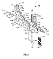
- puncture assembly 100 may be employed to breach the rupture disk 22 ( FIG. 1A ) of a gas cylinder 20.
- the puncture assembly 100 includes a frame 110, which provides a mounting structure for various other components of the puncture assembly 100.
- the frame 110 supports a cam shaft 112, a spring drive assembly 114 and a plunger assembly 116.
- the cam shaft 112 is mounted in a rotatable manner about a first axis A1, and the spring drive assembly is mounted to support longitudinal motion about a second axis A2.
- the cam shaft 112 includes three drum members 120. Each drum includes a circumferential cam surface 122 and a neutral surface 124. The cam surfaces 122 are sloped such that a radius of the respective drum member 120 increases along the cam surface 122 while the neutral surfaces exhibit a constant radius. A longitudinal slot 126 extends along the drum members 120 and separates the cam and neutral surfaces 122, 124.
- the drum members 120 also include a hexagonal drive bore 128 extending longitudinally therethrough. The drive bore of one of the drum members is engaged by a head 130 of a hexagonal drive key 132 such that the drum member 120 rotates along with the drive key 132.
- Each of the drum members 120 may be coupled to adjacent drum members 120 by a coupling member (not shown) having a head similar to head 130 of drive key 132 such that each of the drum members rotates together.
- the drive key 132 is engaged by a pinion gear 134 such that the drive key 132 rotates with the pinion gear 134.
- the frame 110 defines first and second bores 110a and 110b for supporting the cam shaft 112.
- a flanged bushing 136 is press fit into the first bore 110A and receives the drive key 132 such that the drive key 132 is free to rotate therein.
- the drive key 132 is longitudinally secured in the frame 110 with a washer 138 and screw 140 on one side of the bore 110a and an E-ring on an opposite side of the bore 110a.
- the pinion gear 134 is secured to the drive key 132 between the bushing 136 and the E-ring 142.
- a flanged bushing 146 is press fit into the second bore 110b. The bushing 146 receives a hexagonal cap 148 such that the hexagonal cap 148 is free to rotate therein.
- a screw 150 secures the hexagonal cap 148 to a drum member 120 via a coupling member (not shown) having a head that extends into an interior portion the hexagonal cap 148.
- This arrangement permits each drum member 120, the drive key 132, pinion gear 134 and hexagonal cap 148 of the cam shaft 112 to rotate together.
- a cam shaft (not shown) may be configured such that each drum member 120 rotates independently or in another arrangement to facilitate the puncture of multiple cylinders.
- the drive assembly 114 includes a bank of four compression springs 152, which, in combination, have the capacity to store sufficient energy to permit the puncture assembly 100 to puncture at least one rupture disk seal 22 ( FIG. 1A ). In alternative embodiments, including the embodiment discussed below with reference to FIG. 8A and 8B , sufficient energy may also be stored by springs in an elongated or tensile state.
- the drive assembly 114 includes an elongate support plate 154 fixedly mounted to the frame 110 by a coupling member 156 and screws 158.
- the springs 152 are supported on a first L-bracket 160 that is fixedly mounted to the elongate support plate 154 with screws 162.
- a second L-bracket 164 opposes the first L-bracket 160 and engages the springs 152 such that the second L-bracket 164 is longitudinally movable in the direction of the second axis A2.
- the longitudinal position of the second L-bracket 164 depends on the degree of compression in the springs 152.
- a gear rack 166 is fixedly coupled to the second L-bracket 164 such that the gear rack 166 moves longitudinally with the second L-bracket 164.
- the gear rack 166 moves longitudinally within a slot 168 defined in a rack placement bracket 170.
- the rack placement bracket 170 is fixedly coupled to the frame 110.
- the gear rack 166 of the drive assembly 114 engages the pinion gear 134 of the cam shaft 112 such that longitudinal motion in the drive assembly 114 induces rotational motion in the cam shaft 112. Longitudinal movement of the gear rack 166 in the direction of arrow L1 induces rotational motion of the cam shaft 112 in the direction of R1. Similarly, movement of the gear rack 166 in the direction of arrow L2 induces motion of the cam shaft in the direction of arrow R2.
- the plunger assembly 116 engages the cam shaft 112 as the cam shaft 112 rotates.
- the plunger assembly 116 includes a knob support plate 172 fixedly coupled to the frame 110 with screws 174.
- the knob support plate 172 receives a spring-loaded plunger screw 176.
- the plunger screw 176 is positioned such that a head 180 of the plunger screw 176 engages a drum member 120 along the cam surface 122 as the cam shaft 112 rotates freely in the direction of arrow R1 or R2. As the plunger screw 176 encounters the slot 126 of the drum member 120. however, the head 180 extends into the slot 126 to prevent further rotational motion of the cam shaft 112.
- the puncture assembly 100 may be moved to a pre-set configuration wherein the springs 152 are in a compressed state and store energy.
- the gear rack 166 and second L-bracket 164 are moved in the direction of arrow L2 to a pre-set position.
- Release pin 104 engages the second L-bracket 164 to prevent motion of the drive assembly 114.
- the head 180 of the plunger screw 176 engages the cam surface 122 of one of the drum members 120.
- At least one cylinder 20 is screwed into the port 102 approximate the cam shaft 112.
- Multiple ports 182 may be provided to accommodate embodiments wherein multiple cylinders 20 are to be punctured.
- a plug 182 may be provided to prevent gas leakage through any un-used port 102.
- a puncture pin 184 is disposed within the port 102. As depicted in FIG. 5B , the puncture pin 184 includes a sharpened tip portion 184a and a head portion 184b extending out of the port 102. The sharpened tip portion 184a is disposed toward the rupture disk seal 22 and forms a radial seal with an o-ring 186 or similar component.
- the o-ring 186 inhibits leakage of any surgical gas released from cylinder 20 from a passageway 188 leading to plenum 26 ( FIG. 1A ) or gas supply hose 80 ( FIG. 2 ).
- the head portion 184b of the puncture pin 184 engages the cam surface 122 of one of the drum members 120.
- the drum members 120 are positioned such that the head portion 184b engages the cam surface 122 at a location where the radius of the drum member is at a minimum.
- a biasing member (not shown) may be provided such that the head portion 184b maintains contact with the cylinder 120 as the cam shaft 112 rotates.
- the puncture assembly 100 may be actuated to puncture the rupture disk seal 22.
- the release pin 104 is moved to an actuated position wherein the release pin 104 is disengaged from the second L-bracket 164.
- the energy stored in springs 152 is thereby released, driving the second L-bracket 164 and the gear rack 166 in the direction of arrow L1.
- the motion of the gear rack 166 causes the pinion gear 134 ( FIG. 3 ) and cam shaft 112 to rotate in the direction of arrow R1 ( FIG. 4 ).
- the cam surfaces 122 of the drum members 120 drive the puncture pin 184 toward the cylinder 20.
- the springs 152 impart a sufficient torque to the cam shaft 112 to drive the tip portion 184a through the rupture disk seal 22. Surgical gas is then released from the cylinder 20 into the passageway 188 leading toward the plenum 26 ( FIG. 1A ) or gas supply hose 80 ( FIG. 2 ).
- the head 180 of plunger screw 176 engages the slot 126 in one of the drum members 120 to prevent any over-travel of the cam shaft 112.
- an operator may puncture the cylinder 20 with a relatively small input force imparted to the release pin 104.
- the input force is sufficient to actuate the springs 132, but not necessarily sufficient alone to drive puncture pin 184 through the rupture disk seal 22.
- This arrangement may facilitate operation of an electrosurgical instrument 10 ( FIG. 1A ) during a surgical procedure.
- the springs 152 may be compressed, and the release pin 104 may be replaced at a convenient time prior to further surgical procedures.
- the user may have access to the mechanisms required to reset the puncture assembly 100.
- the user may be effectively locked out, thus requiring the instrument 10 to be rebuilt or refurbished by the manufacturer in order to reset the puncture assembly 100.
- the number of springs 152 or the spring constant of the springs 152 may be varied to configure the puncture assembly 100 to store a sufficient amount of energy to puncture a particular type of cylinder or cylinders 20. Additional, the pitch of the gear rack 166 and pinion gear 134 may be varied to accommodate the various puncture forces that may be required.
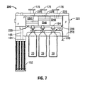
- Puncture assembly 200 is configured to sequentially puncture a series of cylinders 20.
- the cylinders 20 are screwed into a frame 210 having ports 212 similar to ports 102 described above with reference to FIG. 5B .
- the ports 212 are in fluid communication with a passageway 220 leading toward the plenum 26 ( FIG. 1A ) or gas supply hose 80 ( FIG. 2 ), and puncture pins 184 are disposed within the ports 212.
- a bank of springs 152 is provided to store energy for driving gear rack 166 in a longitudinal direction as described above with reference to FIG. 6 . Longitudinal motion of the gear rack 166 induces rotational motion of a cam shaft 222 by engaging pinion gear (not shown) similarly configured and positioned as the pinion gear 134 described above with reference to FIG. 4 .
- the cam shaft 222 includes three drum members 224A, 224B and 224C.
- Each drum member 224A, 224B and 224C includes a slot 226 defined therein, a cam surface 228 and a neutral surface 230.
- the three drum members 224A, 224B and 224C are configured to rotate together, but are oriented with a radial offset with respect to the neighboring drum members 224A, 224B and 224C.
- a first plunger screw 176 engages the slot 226 of drum member 224A, and a respective puncture pin 184 engages the cam surface 228 of the drum member 224A.
- first plunger screw 176 With the slot 226 prevents rotation of the cam shaft 222 under the influence of the energy stored in springs 152. Due to the radial offset of drum members 224B and 224C, respective plunger screws 176 and puncture pins 184 engage the neutral surfaces 230 of drum members 224B and 224C when the puncture assembly 220 is in the preset configuration.
- a first cylinder 20 may be punctured by disengaging the plunger screw 176 from the slot 226 defined in drum member 224A. Disengagement of the plunger screw 176 permits rotation of the cam shaft 222 under the influence of the energy stored in springs 152.
- the cam surface 228 of drum member 224A drives the respective puncture pin 184 into the corresponding cylinder 20 to release the surgical gas therefrom.
- the drum members 224B and 224C engage respective puncture pins 184 along neutral surfaces 230 such that the respective puncture pins 184 do not travel toward or puncture corresponding cylinders 20.
- the cam shaft 222 continues to rotate until the slot 226 defined in drum member 224B encounters a respective plunger screw 176.
- the plunger screw 176 then engages the slot 226 defined in drum member 224B and prevents further rotation of the cam shaft 222.
- the remaining energy stored in springs 152 is sufficient to puncture additional cylinders 20.
- the cam surface 228 of drum member 224B is positioned such that further rotation of the cam shaft 222 drives the respective puncture pin 184 toward the corresponding cylinder 20.
- Puncture assembly 300 includes a bank of extension springs 302 configured to store energy in first tensile state.
- the springs 302 are provided in a stretched configuration such that sufficient energy is stored in the springs 302 to drive cam shaft 322 and puncture cylinder or cylinders 20.
- springs 302 exert a force on the L-bracket 164 in the direction of arrow L2.
- the L-bracket 164 is fixedly coupled to gear rack 166, and the gear rack 166 engages pinion gear 134 ( FIG. 3 ) of cam shaft 322.
- the force exerted by the springs 302 is transmitted to the cam shaft 322.
- the cam shaft 322 is prevented from rotating under the influence of this force by the head 180 of plunger screw 176 extending into the longitudinal slot 126.
- An end opposite the head 180 of the plunger screw 176 extends to an exterior of housing 11 such that the plunger screw 176 is accessible to a user during a coagulation procedure.
- puncture assembly 300 is actuated by manipulating the plunger screw 176.
- the puncture assembly 300 moves from the pre-set configuration depicted in FIG. 8A to an actuated configuration depicted in FIG. 8B .
- the springs 302 move to a relaxed state drawing L-Bracket 164 and gear rack 166 in the direction of arrow L2.
- the longitudinal motion of the gear rack 166 induces rotational motion in the cam shaft 322 such that the orientation of the cam surfaces 122 and neutral surfaces 124 are reversed.
- the cam surfaces 124 engage the puncture pins 184 as the cam shaft 322 rotates, and the puncture pins 184 are driven toward the cylinders 20.
- Puncture assembly 300 permits a user to puncture cylinders 20 by providing only a force sufficient to remove the head 180 from the slot 126. This arrangement may prove to be a viable alternative to directly puncturing the cylinders 20.
Landscapes
- Health & Medical Sciences (AREA)
- Surgery (AREA)
- Engineering & Computer Science (AREA)
- Life Sciences & Earth Sciences (AREA)
- Biomedical Technology (AREA)
- Otolaryngology (AREA)
- Nuclear Medicine, Radiotherapy & Molecular Imaging (AREA)
- Plasma & Fusion (AREA)
- Physics & Mathematics (AREA)
- Heart & Thoracic Surgery (AREA)
- Medical Informatics (AREA)
- Molecular Biology (AREA)
- Animal Behavior & Ethology (AREA)
- General Health & Medical Sciences (AREA)
- Public Health (AREA)
- Veterinary Medicine (AREA)
- Surgical Instruments (AREA)
Claims (15)
- Chirurgisches Instrument zum Bereitstellen eines chirurgischen Gases für eine chirurgische Lokalisation, umfassend:eine Aufnahme zum Aufnehmen eines Zylinders von unter Druck stehendem chirurgischem Gas;einen Rahmen mit einem proximalen und einem distalen Ende, wobei der Rahmen einen Anschluss in der Nähe des distalen Endes definiert, um das chirurgische Gas zu emittieren;einen Durchgangsweg, der sich zwischen der Aufnahme und dem Anschluss, der in dem Rahmen definiert ist, erstreckt; undeine Stechanordnung, um eine Versieglung zu durchbrechen, die durch den Zylinder definiert ist, um das chirurgische Gas in den Durchgangsweg freizugeben, dadurch gekennzeichnet, dass die Stechanordnung umfasst:zumindest einen Speicher zum Speichern mechanischer Energie;einen Aktor, der auf eine Betätigungskraft antwortet, um die mechanische Energie von dem Speicher freizugeben; undeinen Stechstift, der mit dem Speicher derart gekoppelt ist, dass das Freigeben von Energie von dem Speicher den Stechstift in Bezug auf den Zylinder mit einer Stechkraft bewegt, die größer als die Betätigungskraft ist.
- Chirurgisches Instrument nach Anspruch 1, wobei der Speicher zumindest eine Feder aufweist, die zwischen einem komprimierten Zustand zum Speichern mechanischer Energie und einem entspannten Zustand beweglich ist.
- Chirurgisches Instrument zum Bereitstellen eines Gases für eine chirurgische Lokalisation nach Anspruch 1, ferner umfassend:eine Elektrode, die neben dem distalen Ende des Rahmes angeordnet ist, wobei die Elektrode für eine Verbindung mit einer Quelle elektrochirurgischer Energie angepasst ist;den Durchgangsweg zum Zuführen des chirurgischen Gases zu der Elektrode; unddie Stechanordnung zum Durchstoßen einer Versiegelung, die durch den Zylinder definiert ist, um das chirurgische Gas in den Durchgangsweg freizugeben, die ferner derart angepasst ist, dass der Speicherzumindest eine Feder aufweist, die zwischen einem ersten Zustand zum Speichern mechanischer Energie und einem entspannten Zustand beweglich ist;wobei der Aktor betrieben werden kann, um die Feder in den entspannten Zustand zu bewegen; undwobei der Stechstift mit der Feder derart wirkverbunden ist, dass Energie, die durch eine Bewegung der Feder in den entspannten Zustand freigegeben wird, so wirkt, dass sie den Stechstift relativ zu dem Zylinder bewegt, um die Versiegelung zu durchstoßen.
- Chirurgisches Instrument nach Anspruch 3, wobei der Stechstift mit der Feder über eine Zahnstange und ein Zahnrad derart wirkverbunden ist, dass eine Bewegung der Feder in den entspannten Zustand eine Längsbewegung der Zahnstange induziert und die Längsbewegung der Zahnstange eine Rotationsbewegung des Zahnrades induziert.
- Chirurgisches Instrument nach Anspruch 4, wobei das Zahnrad mit einer Nockenwelle wirkgekoppelt ist und wobei eine Rotationsbewegung der Nockenwelle eine Längsbewegung zwischen dem Stechstift und dem Zylinder induziert.
- Chirurgisches Instrument nach Anspruch 5, wobei der Aktor einen Kolben aufweist, der dazu ausgestaltet ist, einen Schlitz in der Nockenwelle derart zu ergreifen, dass ein Trennen des Kolbens von dem Schlitz eine Bewegung der Feder in den entspannten Zustand induziert.
- Chirurgisches Instrument nach Anspruch 5 oder 6, wobei die Aufnahme dazu ausgestaltet ist, mehrere Zylinder aufzunehmen, und wobei die Nockenwelle mehrere Stechstifte derart wirkend ergreift, dass jeder der mehreren Stechstifte relativ zu einem entsprechenden Zylinder beweglich ist.
- Chirurgisches Instrument nach einem der vorhergehenden Ansprüche, wobei die Aufnahme dazu ausgestaltet ist, mehrere Zylinder aufzunehmen, und wobei die Stechanordnung mehrere Stechstifte aufweist, die jeweils gleichzeitig in Bezug auf einander relativ zu einem entsprechenden Zylinder derart beweglich sind, dass jeder der mehreren Zylinder gleichzeitig durchstochen werden kann.
- Chirurgisches Instrument nach einem der Ansprüche 1 bis 7, wobei die Aufnahme dazu ausgestaltet ist, mehrere Zylinder aufzunehmen, und wobei die Stechanordnung mehrere Stechstifte aufweist, die jeweils nacheinander in Bezug aufeinander relativ zu einem entsprechenden Zylinder derart beweglich sind, dass jeder der mehreren Zylinder nacheinander durchstochen werden kann.
- Chirurgisches Instrument nach Anspruch 9, wobei eine Bewegung der Feder in den entspannten Zustand eine Rotationsbewegung in einer Nockenwelle induziert, wobei die Nockenwelle mehrere Nockenoberflächen aufweist, die radial voneinander versetzt sind, und wobei jede der Nockenoberflächen einen entsprechenden Stechstift wirkend ergreift.
- Chirurgisches Instrument nach Anspruch 3 oder einem der Ansprüche 4 bis 10 in Abhängigkeit von Anspruch 3, wobei die zumindest eine Feder eine Kompressionsfeder aufweist, so dass die Kompressionsfeder im ersten Zustand einer Kompressionskraft unterworfen ist.
- Chirurgisches Instrument nach Anspruch 3 oder einem der Ansprüche 4 bis 10 in Abhängigkeit von Anspruch 3, wobei die zumindest eine Feder eine Dehnungsfeder aufweist, so dass die Dehnungsfeder einer Spannungskraft unterworfen ist, wenn sie im ersten Zustand ist.
- Chirurgisches Instrument nach einem der vorhergehenden Ansprüche, wobei die Aufnahme innerhalb des Rahmens angeordnet ist und die Quelle elektrochirurgischer Energie innerhalb des Rahmens angeordnet ist.
- Chirurgisches Instrument nach einem der Ansprüche 1 bis 12, wobei die Aufnahme in Bezug auf den Rahmen entfernt angeordnet ist und wobei der Durchgangsweg einen Gaszuführungsschlauch umfasst.
- Chirurgisches Instrument nach einem der Ansprüche 1 bis 12 und 14, wobei die Quelle elektrochirurgischer Energie in Bezug auf den Rahmen entfernt angeordnet ist und mit dem Rahmen über ein Kabel gekoppelt ist.
Applications Claiming Priority (1)
| Application Number | Priority Date | Filing Date | Title |
|---|---|---|---|
| US12/548,049 US8083737B2 (en) | 2009-08-26 | 2009-08-26 | Gas-enhanced surgical instrument with mechanism for cylinder puncture |
Publications (2)
| Publication Number | Publication Date |
|---|---|
| EP2289441A1 EP2289441A1 (de) | 2011-03-02 |
| EP2289441B1 true EP2289441B1 (de) | 2012-05-23 |
Family
ID=42953796
Family Applications (1)
| Application Number | Title | Priority Date | Filing Date |
|---|---|---|---|
| EP20100174107 Not-in-force EP2289441B1 (de) | 2009-08-26 | 2010-08-26 | Gaserweitertes chirurgisches Instrument mit einem Mechanismus zur Zylinderpunktur |
Country Status (2)
| Country | Link |
|---|---|
| US (3) | US8083737B2 (de) |
| EP (1) | EP2289441B1 (de) |
Families Citing this family (10)
| Publication number | Priority date | Publication date | Assignee | Title |
|---|---|---|---|---|
| US8083737B2 (en) * | 2009-08-26 | 2011-12-27 | Tyco Healthcare Group Lp | Gas-enhanced surgical instrument with mechanism for cylinder puncture |
| US9610412B2 (en) * | 2010-03-02 | 2017-04-04 | Covidien Lp | Internally pressurized medical devices |
| JP2013542788A (ja) | 2010-11-03 | 2013-11-28 | コンストラクト メディカル プロプライエタリー リミテッド | ポータブル真空装置 |
| EP2755716B1 (de) * | 2011-09-15 | 2020-04-15 | Cold Plasma Medical Technologies, Inc. | Unipolare kaltplasmavorrichtungen und verfahren dafür |
| CA2897426A1 (en) * | 2012-01-09 | 2013-07-18 | Somerset Group Enterprises, Inc. | Modular extracorporeal systems and methods for treating blood-borne diseases |
| AU2013344815B2 (en) * | 2012-11-13 | 2018-07-26 | Construct Medical Pty Ltd | A portable suction device |
| US9117636B2 (en) | 2013-02-11 | 2015-08-25 | Colorado State University Research Foundation | Plasma catalyst chemical reaction apparatus |
| DE102013109887A1 (de) * | 2013-09-10 | 2015-03-12 | Reinhausen Plasma Gmbh | Handgerät und Verfahren zur Plasmabehandlung |
| WO2020028420A1 (en) * | 2018-07-31 | 2020-02-06 | L'oreal | Generating cold plasma away from skin, and associated systems and methods |
| KR102031713B1 (ko) * | 2019-01-29 | 2019-10-14 | (주)에스제이글로벌 | 창상치료용 플라즈마 전극 패드 및 플라즈마 치료 장치 |
Family Cites Families (64)
| Publication number | Priority date | Publication date | Assignee | Title |
|---|---|---|---|---|
| FR1340509A (fr) | 1962-11-27 | 1963-10-18 | Siemens Reiniger Werke Ag | Dispositif de sécurité pour appareils de chirurgie à haute fréquence |
| US3688765A (en) * | 1969-10-03 | 1972-09-05 | Jack S Gasaway | Hypodermic injection device |
| US3834433A (en) | 1971-11-22 | 1974-09-10 | A Thompson | Cartridge-actuated device for inflating tires and the like |
| JPS61159953A (ja) | 1985-01-08 | 1986-07-19 | オリンパス光学工業株式会社 | 前立腺切除装置 |
| US20020045811A1 (en) | 1985-03-22 | 2002-04-18 | Carter Kittrell | Laser ablation process and apparatus |
| US4781175A (en) | 1986-04-08 | 1988-11-01 | C. R. Bard, Inc. | Electrosurgical conductive gas stream technique of achieving improved eschar for coagulation |
| SU1438745A1 (ru) | 1986-12-24 | 1988-11-23 | Всесоюзный научно-исследовательский и испытательный институт медицинской техники | Ультразвуковой хирургический инструмент |
| US5041110A (en) * | 1989-07-10 | 1991-08-20 | Beacon Laboratories, Inc. | Cart for mobilizing and interfacing use of an electrosurgical generator and inert gas supply |
| US5306238A (en) | 1990-03-16 | 1994-04-26 | Beacon Laboratories, Inc. | Laparoscopic electrosurgical pencil |
| DE9117299U1 (de) | 1991-11-27 | 2000-03-23 | Erbe Elektromedizin GmbH, 72072 Tübingen | Einrichtung zur Koagulation biologischer Gewebe |
| DE9117019U1 (de) | 1991-11-27 | 1995-03-09 | Erbe Elektromedizin GmbH, 72072 Tübingen | Einrichtung zur Koagulation biologischer Gewebe |
| DE4139029C2 (de) | 1991-11-27 | 1996-05-23 | Erbe Elektromedizin | Einrichtung zur Koagulation biologischer Gewebe |
| US6102046A (en) | 1995-11-22 | 2000-08-15 | Arthrocare Corporation | Systems and methods for electrosurgical tissue revascularization |
| US5720745A (en) * | 1992-11-24 | 1998-02-24 | Erbe Electromedizin Gmbh | Electrosurgical unit and method for achieving coagulation of biological tissue |
| US5693044A (en) | 1992-12-11 | 1997-12-02 | Cosmescu; Ioan | Telescopic surgical device and method therefor |
| DE4326037C2 (de) | 1993-08-03 | 1997-01-16 | Dieter C Dr Med Goebel | Lasereinrichtung |
| EP0651974B1 (de) | 1993-11-10 | 2000-05-03 | Xomed, Inc. | Bipolares, elektrochirurgisches Instrument und Herstellungsverfahren |
| US5669907A (en) * | 1995-02-10 | 1997-09-23 | Valleylab Inc. | Plasma enhanced bipolar electrosurgical system |
| US5669904A (en) * | 1995-03-07 | 1997-09-23 | Valleylab Inc. | Surgical gas plasma ignition apparatus and method |
| US6213999B1 (en) * | 1995-03-07 | 2001-04-10 | Sherwood Services Ag | Surgical gas plasma ignition apparatus and method |
| DE19524645C2 (de) | 1995-07-06 | 2002-11-28 | Soering Gmbh | Sicherheitsgasanlage für die HF-Chirurgie |
| DE19537897A1 (de) | 1995-09-19 | 1997-03-20 | Erbe Elektromedizin | Multifunktionales chirurgisches Instrument |
| US6805130B2 (en) | 1995-11-22 | 2004-10-19 | Arthrocare Corporation | Methods for electrosurgical tendon vascularization |
| US5732752A (en) * | 1996-04-04 | 1998-03-31 | Glessner; Glen R. | Method and apparatus for the automatic release of a gas from a pressurized cartridge |
| US5909086A (en) | 1996-09-24 | 1999-06-01 | Jump Technologies Limited | Plasma generator for generating unipolar plasma |
| DE29724247U1 (de) | 1997-03-20 | 2000-08-03 | Erbe Elektromedizin GmbH, 72072 Tübingen | Einrichtung zur Koagulation biologischer Gewebe |
| JPH1130400A (ja) * | 1997-07-09 | 1999-02-02 | Nippon Kuatsu Syst Kk | 蓄圧装置 |
| DE69827036T2 (de) * | 1997-12-16 | 2006-03-09 | Meridian Medical Technologies, Inc. | Automatische injektionsvorrichtung zur verabreichung eines medikamentes |
| DE19820240C2 (de) | 1998-05-06 | 2002-07-11 | Erbe Elektromedizin | Elektrochirurgisches Instrument |
| US6763836B2 (en) | 1998-06-02 | 2004-07-20 | Arthrocare Corporation | Methods for electrosurgical tendon vascularization |
| DE19848784C2 (de) | 1998-10-22 | 2003-05-08 | Erbe Elektromedizin | Sonde |
| US6958063B1 (en) * | 1999-04-22 | 2005-10-25 | Soring Gmbh Medizintechnik | Plasma generator for radio frequency surgery |
| EP1595507B1 (de) | 1999-10-05 | 2012-03-21 | Covidien AG | Abwinkelbarer, mit ionizierbarem Gas arbeitender Koagulator |
| US6475217B1 (en) | 1999-10-05 | 2002-11-05 | Sherwood Services Ag | Articulating ionizable gas coagulator |
| US6740081B2 (en) * | 2002-01-25 | 2004-05-25 | Applied Medical Resources Corporation | Electrosurgery with improved control apparatus and method |
| US6774569B2 (en) | 2002-07-11 | 2004-08-10 | Fuji Photo Film B.V. | Apparatus for producing and sustaining a glow discharge plasma under atmospheric conditions |
| US7004939B2 (en) | 2002-09-03 | 2006-02-28 | Dale Victor Mackay | Electrosurgical apparatus |
| AU2003904278A0 (en) | 2003-08-13 | 2003-08-28 | Thomas J. Borody | Improved oral oxygenating device |
| US8226643B2 (en) | 2004-02-03 | 2012-07-24 | Covidien Ag | Gas-enhanced surgical instrument with pressure safety feature |
| US8157795B2 (en) * | 2004-02-03 | 2012-04-17 | Covidien Ag | Portable argon system |
| US7572255B2 (en) * | 2004-02-03 | 2009-08-11 | Covidien Ag | Gas-enhanced surgical instrument |
| US7628787B2 (en) | 2004-02-03 | 2009-12-08 | Covidien Ag | Self contained, gas-enhanced surgical instrument |
| US20090054893A1 (en) | 2004-02-03 | 2009-02-26 | Sartor Joe D | Gas-enhanced surgical instrument with pressure safety feature |
| US7833222B2 (en) * | 2004-02-03 | 2010-11-16 | Covidien Ag | Gas-enhanced surgical instrument with pressure safety feature |
| ATE348497T1 (de) | 2004-08-13 | 2007-01-15 | Fuji Photo Film Bv | Verfahren und vorrichtung zur steuerung eines glühentladungsplasmas unter atmosphärischem druck |
| US8920414B2 (en) | 2004-09-10 | 2014-12-30 | Vessix Vascular, Inc. | Tuned RF energy and electrical tissue characterization for selective treatment of target tissues |
| JP2008539007A (ja) | 2005-04-25 | 2008-11-13 | ドレクセル ユニバーシティ | 生体組織へガスプラズマを非熱的に印加する方法 |
| US7632267B2 (en) | 2005-07-06 | 2009-12-15 | Arthrocare Corporation | Fuse-electrode electrosurgical apparatus |
| US20070106288A1 (en) | 2005-11-09 | 2007-05-10 | Arthrocare Corporation | Electrosurgical apparatus with fluid flow regulator |
| US7633216B2 (en) | 2005-11-28 | 2009-12-15 | General Electric Company | Barium-free electrode materials for electric lamps and methods of manufacture thereof |
| ES2342790T3 (es) | 2006-01-03 | 2010-07-14 | Alcon, Inc. | Sistema para la disociacion y retirada de tejido proteinico. |
| US7879034B2 (en) | 2006-03-02 | 2011-02-01 | Arthrocare Corporation | Internally located return electrode electrosurgical apparatus, system and method |
| US7648503B2 (en) | 2006-03-08 | 2010-01-19 | Covidien Ag | Tissue coagulation method and device using inert gas |
| US8123744B2 (en) | 2006-08-29 | 2012-02-28 | Covidien Ag | Wound mediating device |
| US8523926B2 (en) | 2007-01-19 | 2013-09-03 | Joseph Neev | Devices and methods for generation of subsurface microdisruptions for biomedical applications |
| US8475452B2 (en) | 2007-02-21 | 2013-07-02 | Electromedical Associates, Llc | Instruments and methods for thermal tissue treatment |
| GB2458329B (en) | 2008-03-15 | 2012-11-07 | Creo Medical Ltd | Applicator assembly for plasma sterilisation of body cavities |
| ES2565245T3 (es) | 2007-12-20 | 2016-04-01 | Günter Farin | Aplicadores de plasma para procedimientos quirúrgicos por plasma |
| CN102015020A (zh) | 2008-05-09 | 2011-04-13 | 休·贝克曼 | 用于诊断和治疗异常组织的医疗设备及其使用方法 |
| US20120029499A1 (en) | 2008-07-07 | 2012-02-02 | Mattiolli Engineering Ltd. | Method and apparatus for plasma skin resurfacing |
| JP2010242857A (ja) | 2009-04-06 | 2010-10-28 | Toyota Motor Corp | 摩擦損失の低減を求めて噛合い位置を変位させる歯車伝動装置 |
| US8083737B2 (en) * | 2009-08-26 | 2011-12-27 | Tyco Healthcare Group Lp | Gas-enhanced surgical instrument with mechanism for cylinder puncture |
| US8834462B2 (en) | 2010-06-01 | 2014-09-16 | Covidien Lp | System and method for sensing tissue characteristics |
| US8668687B2 (en) | 2010-07-29 | 2014-03-11 | Covidien Lp | System and method for removing medical implants |
-
2009
- 2009-08-26 US US12/548,049 patent/US8083737B2/en not_active Expired - Fee Related
-
2010
- 2010-08-26 EP EP20100174107 patent/EP2289441B1/de not_active Not-in-force
-
2011
- 2011-12-21 US US13/333,697 patent/US8343090B2/en not_active Expired - Fee Related
-
2012
- 2012-12-20 US US13/721,272 patent/US9044219B2/en not_active Expired - Fee Related
Also Published As
| Publication number | Publication date |
|---|---|
| EP2289441A1 (de) | 2011-03-02 |
| US20130110033A1 (en) | 2013-05-02 |
| US20120157911A1 (en) | 2012-06-21 |
| US8083737B2 (en) | 2011-12-27 |
| US8343090B2 (en) | 2013-01-01 |
| US20110054454A1 (en) | 2011-03-03 |
| US9044219B2 (en) | 2015-06-02 |
Similar Documents
| Publication | Publication Date | Title |
|---|---|---|
| US8343090B2 (en) | Gas-enhanced surgical instrument with mechanism for cylinder puncture | |
| EP2298202B1 (de) | Tragbares Argonsystem | |
| CA2495968C (en) | Self contained, gas-enhanced surgical instrument | |
| US8226644B2 (en) | Gas-enhanced surgical instrument | |
| JP5376875B2 (ja) | 電気外科用器具 | |
| EP2319447B1 (de) | Elektrochirurgisches Instrument mit durch einen die Kraft regulierenden Mechanismus betätigbaren Backen | |
| EP0684015B1 (de) | Elektrochirurgische Vorrichtung | |
| EP1532928B1 (de) | Elektrochirurgischer Pistolengriffstift mit manuellem Absauger/Irrigator | |
| US20060052771A1 (en) | Gas-enhanced surgical instrument with pressure safety feature | |
| KR20180131196A (ko) | 외과수술용 의료장치 | |
| JP2000210301A (ja) | 手術機器 | |
| CN120078506B (zh) | 一种冷热疗状态可换的内窥镜用微创切刀及系统 | |
| WO2023117283A1 (en) | Fluid delivery apparatus for a surgical instrument | |
| JP2005245722A (ja) | 外科用手術器械 |
Legal Events
| Date | Code | Title | Description |
|---|---|---|---|
| PUAI | Public reference made under article 153(3) epc to a published international application that has entered the european phase |
Free format text: ORIGINAL CODE: 0009012 |
|
| AK | Designated contracting states |
Kind code of ref document: A1 Designated state(s): AL AT BE BG CH CY CZ DE DK EE ES FI FR GB GR HR HU IE IS IT LI LT LU LV MC MK MT NL NO PL PT RO SE SI SK SM TR |
|
| AX | Request for extension of the european patent |
Extension state: BA ME RS |
|
| RIN1 | Information on inventor provided before grant (corrected) |
Inventor name: HEMPSTEAD, RUSSELL Inventor name: ROOKS, KATHY E. |
|
| 17P | Request for examination filed |
Effective date: 20110811 |
|
| GRAP | Despatch of communication of intention to grant a patent |
Free format text: ORIGINAL CODE: EPIDOSNIGR1 |
|
| RIC1 | Information provided on ipc code assigned before grant |
Ipc: A61B 18/00 20060101AFI20110929BHEP |
|
| GRAS | Grant fee paid |
Free format text: ORIGINAL CODE: EPIDOSNIGR3 |
|
| GRAA | (expected) grant |
Free format text: ORIGINAL CODE: 0009210 |
|
| AK | Designated contracting states |
Kind code of ref document: B1 Designated state(s): AL AT BE BG CH CY CZ DE DK EE ES FI FR GB GR HR HU IE IS IT LI LT LU LV MC MK MT NL NO PL PT RO SE SI SK SM TR |
|
| REG | Reference to a national code |
Ref country code: GB Ref legal event code: FG4D |
|
| REG | Reference to a national code |
Ref country code: CH Ref legal event code: EP |
|
| REG | Reference to a national code |
Ref country code: AT Ref legal event code: REF Ref document number: 558678 Country of ref document: AT Kind code of ref document: T Effective date: 20120615 |
|
| REG | Reference to a national code |
Ref country code: IE Ref legal event code: FG4D |
|
| REG | Reference to a national code |
Ref country code: DE Ref legal event code: R096 Ref document number: 602010001653 Country of ref document: DE Effective date: 20120719 |
|
| REG | Reference to a national code |
Ref country code: NL Ref legal event code: VDEP Effective date: 20120523 |
|
| REG | Reference to a national code |
Ref country code: LT Ref legal event code: MG4D Effective date: 20120523 |
|
| PG25 | Lapsed in a contracting state [announced via postgrant information from national office to epo] |
Ref country code: NO Free format text: LAPSE BECAUSE OF FAILURE TO SUBMIT A TRANSLATION OF THE DESCRIPTION OR TO PAY THE FEE WITHIN THE PRESCRIBED TIME-LIMIT Effective date: 20120823 Ref country code: CY Free format text: LAPSE BECAUSE OF FAILURE TO SUBMIT A TRANSLATION OF THE DESCRIPTION OR TO PAY THE FEE WITHIN THE PRESCRIBED TIME-LIMIT Effective date: 20120523 Ref country code: LT Free format text: LAPSE BECAUSE OF FAILURE TO SUBMIT A TRANSLATION OF THE DESCRIPTION OR TO PAY THE FEE WITHIN THE PRESCRIBED TIME-LIMIT Effective date: 20120523 Ref country code: IS Free format text: LAPSE BECAUSE OF FAILURE TO SUBMIT A TRANSLATION OF THE DESCRIPTION OR TO PAY THE FEE WITHIN THE PRESCRIBED TIME-LIMIT Effective date: 20120923 Ref country code: SE Free format text: LAPSE BECAUSE OF FAILURE TO SUBMIT A TRANSLATION OF THE DESCRIPTION OR TO PAY THE FEE WITHIN THE PRESCRIBED TIME-LIMIT Effective date: 20120523 Ref country code: FI Free format text: LAPSE BECAUSE OF FAILURE TO SUBMIT A TRANSLATION OF THE DESCRIPTION OR TO PAY THE FEE WITHIN THE PRESCRIBED TIME-LIMIT Effective date: 20120523 |
|
| REG | Reference to a national code |
Ref country code: AT Ref legal event code: MK05 Ref document number: 558678 Country of ref document: AT Kind code of ref document: T Effective date: 20120523 |
|
| PG25 | Lapsed in a contracting state [announced via postgrant information from national office to epo] |
Ref country code: GR Free format text: LAPSE BECAUSE OF FAILURE TO SUBMIT A TRANSLATION OF THE DESCRIPTION OR TO PAY THE FEE WITHIN THE PRESCRIBED TIME-LIMIT Effective date: 20120824 Ref country code: HR Free format text: LAPSE BECAUSE OF FAILURE TO SUBMIT A TRANSLATION OF THE DESCRIPTION OR TO PAY THE FEE WITHIN THE PRESCRIBED TIME-LIMIT Effective date: 20120523 Ref country code: LV Free format text: LAPSE BECAUSE OF FAILURE TO SUBMIT A TRANSLATION OF THE DESCRIPTION OR TO PAY THE FEE WITHIN THE PRESCRIBED TIME-LIMIT Effective date: 20120523 Ref country code: SI Free format text: LAPSE BECAUSE OF FAILURE TO SUBMIT A TRANSLATION OF THE DESCRIPTION OR TO PAY THE FEE WITHIN THE PRESCRIBED TIME-LIMIT Effective date: 20120523 Ref country code: PT Free format text: LAPSE BECAUSE OF FAILURE TO SUBMIT A TRANSLATION OF THE DESCRIPTION OR TO PAY THE FEE WITHIN THE PRESCRIBED TIME-LIMIT Effective date: 20120924 |
|
| RAP2 | Party data changed (patent owner data changed or rights of a patent transferred) |
Owner name: COVIDIEN LP |
|
| PG25 | Lapsed in a contracting state [announced via postgrant information from national office to epo] |
Ref country code: BE Free format text: LAPSE BECAUSE OF FAILURE TO SUBMIT A TRANSLATION OF THE DESCRIPTION OR TO PAY THE FEE WITHIN THE PRESCRIBED TIME-LIMIT Effective date: 20120523 |
|
| PG25 | Lapsed in a contracting state [announced via postgrant information from national office to epo] |
Ref country code: RO Free format text: LAPSE BECAUSE OF FAILURE TO SUBMIT A TRANSLATION OF THE DESCRIPTION OR TO PAY THE FEE WITHIN THE PRESCRIBED TIME-LIMIT Effective date: 20120523 Ref country code: EE Free format text: LAPSE BECAUSE OF FAILURE TO SUBMIT A TRANSLATION OF THE DESCRIPTION OR TO PAY THE FEE WITHIN THE PRESCRIBED TIME-LIMIT Effective date: 20120523 Ref country code: NL Free format text: LAPSE BECAUSE OF FAILURE TO SUBMIT A TRANSLATION OF THE DESCRIPTION OR TO PAY THE FEE WITHIN THE PRESCRIBED TIME-LIMIT Effective date: 20120523 Ref country code: DK Free format text: LAPSE BECAUSE OF FAILURE TO SUBMIT A TRANSLATION OF THE DESCRIPTION OR TO PAY THE FEE WITHIN THE PRESCRIBED TIME-LIMIT Effective date: 20120523 Ref country code: SK Free format text: LAPSE BECAUSE OF FAILURE TO SUBMIT A TRANSLATION OF THE DESCRIPTION OR TO PAY THE FEE WITHIN THE PRESCRIBED TIME-LIMIT Effective date: 20120523 Ref country code: AT Free format text: LAPSE BECAUSE OF FAILURE TO SUBMIT A TRANSLATION OF THE DESCRIPTION OR TO PAY THE FEE WITHIN THE PRESCRIBED TIME-LIMIT Effective date: 20120523 Ref country code: CZ Free format text: LAPSE BECAUSE OF FAILURE TO SUBMIT A TRANSLATION OF THE DESCRIPTION OR TO PAY THE FEE WITHIN THE PRESCRIBED TIME-LIMIT Effective date: 20120523 |
|
| PG25 | Lapsed in a contracting state [announced via postgrant information from national office to epo] |
Ref country code: PL Free format text: LAPSE BECAUSE OF FAILURE TO SUBMIT A TRANSLATION OF THE DESCRIPTION OR TO PAY THE FEE WITHIN THE PRESCRIBED TIME-LIMIT Effective date: 20120523 Ref country code: IT Free format text: LAPSE BECAUSE OF FAILURE TO SUBMIT A TRANSLATION OF THE DESCRIPTION OR TO PAY THE FEE WITHIN THE PRESCRIBED TIME-LIMIT Effective date: 20120523 |
|
| PG25 | Lapsed in a contracting state [announced via postgrant information from national office to epo] |
Ref country code: MC Free format text: LAPSE BECAUSE OF NON-PAYMENT OF DUE FEES Effective date: 20120831 |
|
| PLBE | No opposition filed within time limit |
Free format text: ORIGINAL CODE: 0009261 |
|
| STAA | Information on the status of an ep patent application or granted ep patent |
Free format text: STATUS: NO OPPOSITION FILED WITHIN TIME LIMIT |
|
| PG25 | Lapsed in a contracting state [announced via postgrant information from national office to epo] |
Ref country code: ES Free format text: LAPSE BECAUSE OF FAILURE TO SUBMIT A TRANSLATION OF THE DESCRIPTION OR TO PAY THE FEE WITHIN THE PRESCRIBED TIME-LIMIT Effective date: 20120903 |
|
| 26N | No opposition filed |
Effective date: 20130226 |
|
| REG | Reference to a national code |
Ref country code: IE Ref legal event code: MM4A |
|
| REG | Reference to a national code |
Ref country code: DE Ref legal event code: R097 Ref document number: 602010001653 Country of ref document: DE Effective date: 20130226 |
|
| PG25 | Lapsed in a contracting state [announced via postgrant information from national office to epo] |
Ref country code: IE Free format text: LAPSE BECAUSE OF NON-PAYMENT OF DUE FEES Effective date: 20120826 Ref country code: BG Free format text: LAPSE BECAUSE OF FAILURE TO SUBMIT A TRANSLATION OF THE DESCRIPTION OR TO PAY THE FEE WITHIN THE PRESCRIBED TIME-LIMIT Effective date: 20120823 |
|
| PG25 | Lapsed in a contracting state [announced via postgrant information from national office to epo] |
Ref country code: AL Free format text: LAPSE BECAUSE OF FAILURE TO SUBMIT A TRANSLATION OF THE DESCRIPTION OR TO PAY THE FEE WITHIN THE PRESCRIBED TIME-LIMIT Effective date: 20120523 Ref country code: MT Free format text: LAPSE BECAUSE OF FAILURE TO SUBMIT A TRANSLATION OF THE DESCRIPTION OR TO PAY THE FEE WITHIN THE PRESCRIBED TIME-LIMIT Effective date: 20120523 |
|
| PG25 | Lapsed in a contracting state [announced via postgrant information from national office to epo] |
Ref country code: TR Free format text: LAPSE BECAUSE OF FAILURE TO SUBMIT A TRANSLATION OF THE DESCRIPTION OR TO PAY THE FEE WITHIN THE PRESCRIBED TIME-LIMIT Effective date: 20120523 |
|
| PG25 | Lapsed in a contracting state [announced via postgrant information from national office to epo] |
Ref country code: LU Free format text: LAPSE BECAUSE OF NON-PAYMENT OF DUE FEES Effective date: 20120826 Ref country code: SM Free format text: LAPSE BECAUSE OF FAILURE TO SUBMIT A TRANSLATION OF THE DESCRIPTION OR TO PAY THE FEE WITHIN THE PRESCRIBED TIME-LIMIT Effective date: 20120523 |
|
| PG25 | Lapsed in a contracting state [announced via postgrant information from national office to epo] |
Ref country code: HU Free format text: LAPSE BECAUSE OF FAILURE TO SUBMIT A TRANSLATION OF THE DESCRIPTION OR TO PAY THE FEE WITHIN THE PRESCRIBED TIME-LIMIT Effective date: 20100826 |
|
| REG | Reference to a national code |
Ref country code: CH Ref legal event code: PL |
|
| PG25 | Lapsed in a contracting state [announced via postgrant information from national office to epo] |
Ref country code: LI Free format text: LAPSE BECAUSE OF NON-PAYMENT OF DUE FEES Effective date: 20140831 Ref country code: CH Free format text: LAPSE BECAUSE OF NON-PAYMENT OF DUE FEES Effective date: 20140831 |
|
| PG25 | Lapsed in a contracting state [announced via postgrant information from national office to epo] |
Ref country code: MK Free format text: LAPSE BECAUSE OF FAILURE TO SUBMIT A TRANSLATION OF THE DESCRIPTION OR TO PAY THE FEE WITHIN THE PRESCRIBED TIME-LIMIT Effective date: 20120523 |
|
| REG | Reference to a national code |
Ref country code: FR Ref legal event code: PLFP Year of fee payment: 7 |
|
| REG | Reference to a national code |
Ref country code: FR Ref legal event code: PLFP Year of fee payment: 8 |
|
| REG | Reference to a national code |
Ref country code: FR Ref legal event code: PLFP Year of fee payment: 9 |
|
| PGFP | Annual fee paid to national office [announced via postgrant information from national office to epo] |
Ref country code: GB Payment date: 20200722 Year of fee payment: 11 |
|
| PGFP | Annual fee paid to national office [announced via postgrant information from national office to epo] |
Ref country code: FR Payment date: 20210722 Year of fee payment: 12 |
|
| PGFP | Annual fee paid to national office [announced via postgrant information from national office to epo] |
Ref country code: DE Payment date: 20210720 Year of fee payment: 12 |
|
| GBPC | Gb: european patent ceased through non-payment of renewal fee |
Effective date: 20210826 |
|
| PG25 | Lapsed in a contracting state [announced via postgrant information from national office to epo] |
Ref country code: GB Free format text: LAPSE BECAUSE OF NON-PAYMENT OF DUE FEES Effective date: 20210826 |
|
| REG | Reference to a national code |
Ref country code: DE Ref legal event code: R119 Ref document number: 602010001653 Country of ref document: DE |
|
| PG25 | Lapsed in a contracting state [announced via postgrant information from national office to epo] |
Ref country code: FR Free format text: LAPSE BECAUSE OF NON-PAYMENT OF DUE FEES Effective date: 20220831 Ref country code: DE Free format text: LAPSE BECAUSE OF NON-PAYMENT OF DUE FEES Effective date: 20230301 |