EP2289417B1 - Appareil de mammographie par tomographie tridimensionnelle associée par ordinateur - Google Patents
Appareil de mammographie par tomographie tridimensionnelle associée par ordinateur Download PDFInfo
- Publication number
- EP2289417B1 EP2289417B1 EP10185587A EP10185587A EP2289417B1 EP 2289417 B1 EP2289417 B1 EP 2289417B1 EP 10185587 A EP10185587 A EP 10185587A EP 10185587 A EP10185587 A EP 10185587A EP 2289417 B1 EP2289417 B1 EP 2289417B1
- Authority
- EP
- European Patent Office
- Prior art keywords
- breast
- gantry frame
- flat panel
- radiation
- panel detector
- Prior art date
- Legal status (The legal status is an assumption and is not a legal conclusion. Google has not performed a legal analysis and makes no representation as to the accuracy of the status listed.)
- Expired - Lifetime
Links
- 0 CCC*C1CC(C)CC1 Chemical compound CCC*C1CC(C)CC1 0.000 description 2
- JAPMJSVZDUYFKL-UHFFFAOYSA-N C1C2C1CCC2 Chemical compound C1C2C1CCC2 JAPMJSVZDUYFKL-UHFFFAOYSA-N 0.000 description 1
Images


Classifications
-
- A—HUMAN NECESSITIES
- A61—MEDICAL OR VETERINARY SCIENCE; HYGIENE
- A61B—DIAGNOSIS; SURGERY; IDENTIFICATION
- A61B6/00—Apparatus for radiation diagnosis, e.g. combined with radiation therapy equipment
- A61B6/50—Clinical applications
- A61B6/502—Clinical applications involving diagnosis of breast, i.e. mammography
-
- A—HUMAN NECESSITIES
- A61—MEDICAL OR VETERINARY SCIENCE; HYGIENE
- A61B—DIAGNOSIS; SURGERY; IDENTIFICATION
- A61B6/00—Apparatus for radiation diagnosis, e.g. combined with radiation therapy equipment
- A61B6/02—Devices for diagnosis sequentially in different planes; Stereoscopic radiation diagnosis
- A61B6/027—Devices for diagnosis sequentially in different planes; Stereoscopic radiation diagnosis characterised by the use of a particular data acquisition trajectory, e.g. helical or spiral
-
- A—HUMAN NECESSITIES
- A61—MEDICAL OR VETERINARY SCIENCE; HYGIENE
- A61B—DIAGNOSIS; SURGERY; IDENTIFICATION
- A61B6/00—Apparatus for radiation diagnosis, e.g. combined with radiation therapy equipment
- A61B6/02—Devices for diagnosis sequentially in different planes; Stereoscopic radiation diagnosis
- A61B6/03—Computerised tomographs
- A61B6/032—Transmission computed tomography [CT]
-
- A—HUMAN NECESSITIES
- A61—MEDICAL OR VETERINARY SCIENCE; HYGIENE
- A61B—DIAGNOSIS; SURGERY; IDENTIFICATION
- A61B6/00—Apparatus for radiation diagnosis, e.g. combined with radiation therapy equipment
- A61B6/04—Positioning of patients; Tiltable beds or the like
- A61B6/0407—Supports, e.g. tables or beds, for the body or parts of the body
- A61B6/0435—Supports, e.g. tables or beds, for the body or parts of the body with means for imaging suspended breasts
-
- A—HUMAN NECESSITIES
- A61—MEDICAL OR VETERINARY SCIENCE; HYGIENE
- A61B—DIAGNOSIS; SURGERY; IDENTIFICATION
- A61B6/00—Apparatus for radiation diagnosis, e.g. combined with radiation therapy equipment
- A61B6/06—Diaphragms
-
- A—HUMAN NECESSITIES
- A61—MEDICAL OR VETERINARY SCIENCE; HYGIENE
- A61B—DIAGNOSIS; SURGERY; IDENTIFICATION
- A61B6/00—Apparatus for radiation diagnosis, e.g. combined with radiation therapy equipment
- A61B6/48—Diagnostic techniques
- A61B6/481—Diagnostic techniques involving the use of contrast agents
-
- A—HUMAN NECESSITIES
- A61—MEDICAL OR VETERINARY SCIENCE; HYGIENE
- A61B—DIAGNOSIS; SURGERY; IDENTIFICATION
- A61B6/00—Apparatus for radiation diagnosis, e.g. combined with radiation therapy equipment
- A61B6/50—Clinical applications
- A61B6/504—Clinical applications involving diagnosis of blood vessels, e.g. by angiography
Definitions
- the clinical goal of breast imaging is to detect tumor masses when they are as small as possible, preferably less than 10 mm in diameter. It is reported that women with mammographically detected, 1-10 mm invasive breast carcinoma have a 93% 16-year survival rate.
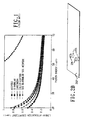
- carcinoma has different x-ray linear attenuation coefficients from surrounding tissues, as shown in figure 1 .
- carcinoma has a substantially higher volume growth rate compared to a benign tumor which lacks growth.
- carcinoma has patterns distinguishable from those of a benign tumor.
- benign tumors show no contrast enhancement after intravenous contrast injection.
- the presence of neovascularity can indicate cancer.
- Conventional mammography relies mainly on the first characteristic and partially uses the third characteristic for breast cancer detection. Since mammography is a two-dimensional static imaging technique, it cannot provide any information regarding characteristics 2, 4, or 5.
- Standard fan beam computed tomography has been evaluated as a potential tool for the characterization of breast lesions.
- Most previous work has been based on the traditional or helical technique using the whole body scanner. That technique, however, suffers from a number of disadvantages including significantly increased radiation exposure due to the fact that standard CT can not be used to target only the breast, so that the majority of x-rays are wasted on whole body scanning. That leads to relatively low in-plane spatial resolution (typically 1. 0 Ip/mm), even lower through plane resolution (less than or equal to 0.5 Ip/mm in the direction perpendicular to slices), and prolonged volume scanning times, since spiral CT scans the whole volume slice by slice and takes 120 seconds for the whole breast scan. It still takes 15-30 seconds for the latest multi-ring spiral CT for 1 mm/slice and 12 cm coverage.
- Ultrasound has poor resolution in characterizing lesion margins and identifying microcalcifications. Ultrasound is also extremely operator dependent.
- US4015836 discloses a mammography machine according to the preamble of claim 1 for the examination of a pendant breast contained in a fluid transmission medium.
- Patient support is provided at the upper rib cage, lower rib cage, and the shoulder adjacent the breast undergoing examination; X-ray scans are accomplished by rotation about a vertical axis extending through the pendant breast.
- VOI volume of interest
- IV intravenous
- the present invention is directed to a device according to claim 1 incorporating a cone beam volume tomographic reconstruction technique with the recently developed flat panel detector to achieve cone beam volume computed tomographic mammography (CBVCTM).
- CBVCTM cone beam volume computed tomographic mammography
- a flat panel-based cone beam volume computed tomography mammography (CBVCTM) imaging system can be constructed, and three-dimensional (3D) reconstructions of a breast from a single fast volume scan (4.8-9.6 seconds) can be obtained.
- the flat panel-based CBVCTM system can provide the ability to tomographically isolate an object of interest (e.g., a lesion) from an adjacent object (e.g., other lesion or calcification).
- the 3D tomographic reconstructions eliminate lesion overlap and provide a complete, true 3D description of the breast anatomy.
- CT computed tomography
- the CBVCTM reconstructions can have 2 lp/mm of isotropic spatial resolution (or, more generally, better than 1 lp/mm) along all three axes.
- CBVCTM ultrahigh resolution volume of interest
- CBVCTM can have many times better contrast detectability (tomographic imaging can have up to 0.1 % contrast detectability) than that of conventional mammography.
- the present invention provides better detection of breast cancers, better lesion characterization, and more accurate preoperative and postoperative information on breast anatomy, thus reducing the negative biopsy rate.
- the present imaging technique has significant clinical impact on breast cancer detection, diagnosis and the evaluation of the effectiveness of therapy. Because of its excellent low contrast detectability and high and isotropic resolution, the present invention significantly improves the accuracy of breast lesion detection, and hence greatly reduces the biopsy rate.
- the potential clinical applications of such a modality are in the imaging of the mammographically indeterminate lesions, the mammographically dense breast and the post-surgical breast. Currently, most mammographically indeterminate lesions end up being biopsied in order to arrive at a definitive diagnosis. It is well known that the usefulness of mammography in patients with dense breasts is limited and that additional imaging or biopsy is frequently required.
- CBVCTM can potentially improve the differentiation of recurrence and form post-surgical changes.
- the present invention provides very high-resolution tomographic images by zooming in on small lesions or specific regions within a tumor.
- Detailed interrogation of specific areas within a lesion e.g., microcalcifications, necrotic and cystic as well as areas of intraductal extension enables more accurate characterization of breast lesions.
- the use of contrast material and dynamic imaging provides additional temporal information, which, together with morphological features, enhances specificity and reduces the biopsy rate.
- Tumor angiogenesis is an independent prognostic indicator in breast cancer.
- angiogenesis is determined by assessing microvessel density in pathologic specimens.
- researchers have also detected good correlation between contrast enhancement and microvessel density.
- contrast medium in an imaging modality that provides very high spatial and temporal resolution offers a non-invasive method to assess tumor angiogenesis.
- the acquisition of volumetric data with 3D rendering allows multiplanar imaging and better presurgical planning, especially in limited resections.
- CBVCTM with the potential for obtaining a very resolution images, offers improved lesion characterization in mammographically indeterminate breast lesions with a view to reducing the biopsy rate. It also offers the advantages of enhancing preoperative and postoperative planning.
- CBVCTM has the capacity to provide information regarding characteristics 1-5 discussed above with reference to the prior art to improve lesion detection and characterization.
- the patient lies face down on an ergonomic patient table having one or two breast holes.
- the gantry holding the x-ray source and the flat panel detector rotates below the table to image the breast or breasts.
- One advantage of having two breast holes is to preserve the geometric relationship between the breasts.
- the patient stands before the gantry.
- a cone beam volume CT reconstruction technique with a flat panel detector.
- a flat panel-based cone beam volume computed tomographic mammography (CBVCTM) imaging system can be constructed as shown in Figs. 2A-2C , and three-dimensional (3D) reconstructions of a breast from a single fast volume scan can be obtained.
- the flat panel-based CBVCTM system provides the ability to tomographically isolate an object ofinterest (e.g. a lesion) from the adjacent plane (e.g. other lesion or calcification).
- the 3D tomographic reconstructions eliminate lesion overlap and provide a complete, true 3D description of breast anatomy.
- the CBVCTM reconstructions can have 2 lp/mm of isotropic spatial resolution.
- An ultrahigh resolution volume of interest (VOI) reconstruction can be produced by using the zoom mode of the flat panel detector to achieve up to 54 lp/mm or better resolution.
- An FPD-based CBVCTM can be built with slip ring technology.
- a slip ring is an electromechanical device allowing the transmission of electrical power, signals or both across a rotating interface.
- One source of slip rings is Fabricast, Inc., of South El Monte, California, U.S.A.
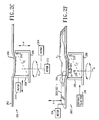
- the schematic design of the CBVCTM scanner is shown in Figs. 2A-2C .
- the CBVCTM scanner has an ergonomic patient table design and scanning geometry especially suitable for target imaging.
- the patient P rests on an ergonomically formed table 202 so that the breast B to be scanned descends through a hole 204 in the table 202 into a breast holder 205.
- the breast holder 205 which will be described in greater detail below, forms the breast B into a cylindrical shape for scanning, which is more comfortable for most patients than the conventional flattened shape.
- a gantry 206 supports a detector 208 and an x-ray tube 210, one on either side of the breast holder 205.
- the gantry is turned by a motor 212 to be rotatable around an axis A passing through the breast holder 205, so that as the x-ray tube travels along an orbit O, the breast B remains in the path of a cone beam C emitted by the x-ray tube 210.
- the gantry is also movable by a motor 214 to go up and down along a vertical path V.
- the detector 208 can be moved toward and away from the axis A by a motor 216 to change the magnification factor if necessary.
- the breast holder 205 is relatively rigid and is made of a material with low x-ray attenuation.
- the breast holder is shown as being part of the table 202, but it can alternatively be made part of the gantry 206.
- the breast holder 205 pulls the breast out of the chest wall to assure proper imaging of the chest wall and applies a light and reproducible compression to form the breast into a cylindrical shape.
- a piston 218 may be used to push the nipple toward the chest wall to reduce z-direction coverage by a couple of centimeters. That piston-pushing reduces the required cone angle ofthe x-ray beam.
- the piston-pushing improves uniformity of breast thickness.
- a contrast injector 220 can be provided for contrast injection tomography.
- Various contrast injection media such as iodine, are known in the art. It is not always necessary to inject a contrast medium into the patient.
- the table 202 can be replaced with the table 202' of Fig. 2D .
- the table 202' is formed like the table 202, except that two breast holes 204 are provided, each with a breast holder 205.
- the table 202' is movable. One breast is moved into the imaging field and is scanned first. Then the other breast is moved into the imaging field and scanned. Thus, the geometric relationship between the breasts is preserved.
- the scan or scans can be performed while the patient is standing.
- a breast holder 205 is supported by a stand 222 to support a breast of a standing patient.
- two breast holders 205 can be provided on the stand 222.
- the gantry 206, holding the detector 208 and the x-ray tube 210, is oriented to rotate around a horizontal axis A' rather than the vertical axis A of Figs. 2A-2C .
- the system 200' can be like the system shown in Figs. 2A-2C .
- the circuitry of the scanner 200 is shown in Fig. 3 .
- a computer 302 on the gantry 206 is connected through a slip ring 304 on a shaft of the gantry 206 to a host computer system 306.
- the computer 302 on the gantry 206 is also in communication with the detector 208, while both computers 302 and 306 are in communication with various other devices on the gantry 206, as explained below.
- the computer 306 is further in communication with a user control and graphics user interface 308.
- the CPU 310 is in communication with the detector 208 through a digital frame grabber 312 and a flat panel controller 314.
- the CPU 310 is also in communication with a memory buffer 316, disk storage 318 and a real-time lossless image compression module 320; through the compression module 320, the CPU 310 communicates with a CBVCTM data transfer module 322 on the gantry 206.
- the CPU 310 directly communicates with two other devices on the gantry, namely, the gantry control 324 and the x-ray control 326.
- a host computer CPU 328 communicates with the data transfer module 322, both directly and through a real-time image decompression module 330.
- the CPU 328 is also in communication with a memory buffer 332, disk storage 334 and a parallel accelerating image reconstruction and processing module 336. Through an image output 338, the CPU 328 communicates with the interface 308.
- the CPU's 310 and 328 communicate with each other through the slip ring 304. Also, although it is not shown in Fig. 3 for simplicity, all communication between components on the gantry 206 and the host computer system 306 take place through the slip ring 304.
- the slip ring 304 and a fast gantry 206 permit optimal CPL scanning with a quasi-spiral scanning scheme and fast dynamic contrast studies. With that design, a CBVCTM scan can be completed within 8 seconds, and several sets of scans can be performed continuously for dynamic contrast studies and angiogenesis studies.
- the locus of an x-ray source and a detector is a single circle during cone beam scanning (single circle cone-beam geometry)
- an incomplete set of projection data is acquired.
- the incompleteness of the projection data results in some unavoidable blurring in the planes away from the central z-plane and resolution loss in the z direction.
- Feldkamp's algorithm which is based on a single circle cone beam geometry
- the magnitude of the reconstruction error due to the incompleteness of projection data is increased with cone angle.
- Computer simulation indicates that for mammography imaging and an average breast size (10 cm in height or smaller), the reconstruction error is relatively small ( ⁇ 5%), and no streak artifacts can be observed.
- a modified Feldkamp's algorithm is used for small and average breast sizes ( ⁇ 10 cm in height), and a circle-plus-line (CPL) cone beam orbit and its corresponding filter backprojection algorithm are used for a large breast (> 10 cm in height). That approach solves the problem of the incompleteness of projection data from a single circle cone beam geometry for mammography scanning.
- a suitable modified Feldkamp's algorithm is taught in Hu, H., "A new cone beam reconstruction algorithm and its application to circular orbits," SPIE 1994; 2163:223-234 .
- a suitable algorithm for CPL is taught in Hu, H., "Exact regional reconstruction of longitudinally-unbounded objects using the circle-and-line cone beam tomographic," Proc. SPIE, Vol. 3032, pp. 441-444, 1997 ; and in Hu, H., "An improved cone-beam reconstruction algorithm for the circular orbit," Scanning 1996, 18:572-581 .
- the circular scan can be implemented with the CBVCTM scanner in the following manner: 1) position the patient's breast B into the hole 204 in the patient table 202 with a lightly-compressed breast holder 205 to form the breast into a cylinder-like shape; 2) rotate the gantry 206 to acquire a set of circle projections.
- the CPL scan can be implemented using a quasi-spiral scan with slip ring technology in the following three steps: 1) position the patient's breast B into the hole 204 in the patient table 202 with a lightly-compressed breast holder 205 to form the breast into a cylinder-like shape; 2) rotate the gantry 206 to acquire a set of circle projections; and 3) once the circle projection is completed, control the gantry 206 to move down and rotate, taking projections only at rotation angles 0° and 180° to acquire two line projections per rotation. It is anticipated that 2-6 line projections are needed to reconstruct a rather large size breast.
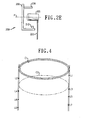
- Fig. 4 shows circular orbits C1 and C2 and positions L1, L2, L3, L4, L5, L6, L7 and L8 at which line projections are taken during one possible scan.
- Figs. 7A-7G show examples of the above steps.
- Fig. 7A shows the ergonomic table 202 with the breast hole 204.
- the patient P is lying on the table 202 with one breast B extending through the hole 204.
- the breast holder 205 which is provided in two halves 205a and 205b, is placed around the breast B, and the piston 218 is placed under the breast B.
- Fig. 7E the two halves 205a and 205b of the breast holder 205 and the piston 218 are brought together to compress the breast B into the desired cylindrical shape.
- Fig. 7A shows the ergonomic table 202 with the breast hole 204.
- Figs. 7B and 7C the patient P is lying on the table 202 with one breast B extending through the hole 204.
- the breast holder 205 which is provided in two halves 205a and 205b, is placed around the breast B, and the piston 218 is placed under the breast B.
- Fig. 7E the two halves 205a
- the gantry 206 carrying the detector 208 and the x-ray tube 210, is placed in position around the breast B.
- the gantry 206 is rotating, and the breast B is imaged by a cone beam C emitted by the x-ray tube 210.
- CBVCTM does not require hard breast compression but prefers a cylindrical formation to improve the geometric reproducibility of 3D-breast imaging. Without hard compression, the maximum thickness of the breast for CBVCTM is much larger, compared to that of conventional mammography.
- the volume scanning speed will be limited by the maximum frame rate of a real time FPD.
- the current available real time FPD has a frame rate of 60-120 frames/sec.
- flat panel researchers predict that the future frame rate can be up to 120 frames/sec. (1K x 1K pixels/frame) and 480 frames/sec with reduced vertical readout lines (256 x 1K pixels/frame).
- the frame rate of the detector is increased to 480 frames/sec. in the future, the volume scanning time of the breast will be shortened to 1-2 seconds depending on the required resolution, and/or the projection number can be increased to improve image quality.
- the FPD-based CBVCTM scanner represents a significant technological advancement due to using a flat panel detector, slip ring technology, and cone beam reconstruction algorithms that result in accurate reconstruction.
- FS-CCD fluorescent screen-CCD area detectors
- II-CCD image intensifier-CCD
- FPD flat panel detectors
- an II-CCD-based system has some disadvantages such as bulky size, which is not suitable for mammography, limited dynamic range (1000-3000:1), geometric distortion (pincushion and S distortions) and veiling glare, which limit further improvement in low-contrast and spatial resolution. Therefore, an FPD is preferred.
- the FPD can be a thin-film transistor array FPD which can acquire both static digital images (radiographic images) and dynamic images (real-time acquisition).
- Another preferred FPD is any area detector with a resolution better than 1 lp/mm and an acquisition rate better than 10 frames per second which can acquire both static digital images and dynamic images.
- CBVCTM Developing and optimizing an x-ray scatter control and reduction technique is one big challenge for CBVCTM because CBVCTM is less immune to scatter than fan-beam CT.
- CBVCTM image contrast is reduced by scatter without an effective control technique.
- Scatter can be countered with a hybrid technique that uses an air gap technique to control scatter and a practical software correction technique for detected scatter.
- One of the major differences between fan beam slice CT and CBVCTM is x-ray beam collimation. Using very narrow slit collimation in fan beam CT reduces scatter-to-primary ratio (SPR) to 0.2 or less.
- SPR scatter-to-primary ratio
- using a large cone collimation in cone beam geometry for mammography with only an air gap technique results in an average SPR up to 1 for average breast thickness.
- an antiscatter grid is not used for an average size breast.
- a software correction technique is used to correct for detected scatter and to reduce overall average SPR to 0.2 or less.
- Convolution filtering techniques and scatter detected by the FPD are used to estimate scatter distribution and then subtract it from the total projection.
- a known convolution filtering technique taught in Love, L.A., and Kruger, R.A., "Scatter estimation for a digital radiographic system using convolution filter,” Med. Phys. 1987; 14(2):178-185 was implemented for an image intensifier-based imaging system and produced an average percentage error of 6.6% for different anatomy and different clinical applications. That is equivalent to a reduction of SPR by a factor of up to 14.
- the preferred embodiment combines an air gap technique with an antiscatter grid and a software correction technique for residual scatter.
- a 10-15 cm air gap technique is an effective method to prevent large angle scatter radiation from reaching the detector and to reduce average SPR to less than 1. It is contemplated that in the CBVCT system, the distance from the rotation center to the detector will be 20 cm. With that geometry, the air gap is more than 15 cm to achieve an average SPR less than 1.
- the residual scatter present within the projection images is removed based on a convolution-filtering method to estimate residual scatter distribution in each projection image.
- residual scatter is modeled as a low pass, spatially filtered version of the total projection (scatter plus primary). After estimating residual scatter in each projection, the residual scatter radiation is then subtracted to obtain primary distribution for reconstruction. That technique effectively reduces SPR from 1.0 to 0.2 or less.
- the conventional convolution filtering method requires two x-ray projections at each projection angle to accurately estimate residual scatter: one with a beam stop array for calculating two scaling factors and another without the beam stop array. That is not practical and would significantly increase patient dose in CBVCTM.
- the preferred embodiment uses scout images for estimating scatter distribution in "real time" for each patient. Before starting to scan, one scout projection image is acquired, as in a standard fan beam CT. Traditionally, the scout images are used for positioning, and surveying body size to adjust the x-ray exposure levels in real time and reduce patient dose (as with 'Smart ScanTM' in a GE helical CT). Before acquiring scout images, as shown in Figs.
- a square matrix 504 of small lead ball bearings 506 is placed between the x-ray collimator 502 and the breast B.
- Both primary and sampled scatter distributions are estimated from the scout images with the lead beam stop array.
- the estimated primary images are used for a scouting purpose.
- the scaling factors for estimating scatter distribution and the convolution kernels at sampled angle positions can be determined.
- the scatter distributions are estimated using the convolution kernel at corresponding angle positions and subtracted from the detected projections.
- the exponential kernel is used for the estimation of residual scatter because a 2D exponential kernel is an optimum formation.
- the same 2D exponential kernel is used for all the projections since after being compressed, the breast has a cylindrical shape and the scatter distribution is almost unchanged with angle positions.
- Figs. 6A-6C show a dynamic collimator 601 usable with CBVCTM in any of the embodiments disclosed above.
- the dynamic collimator 601 includes a collimator body 603 of lead or another suitable material with an aperture 605 therein for admitting only a desired portion 607 of the x-rays emitted by the x-ray source 210.
- the collimator body 603 canbe formed in any suitable manner, but it is preferably formed with two lead leaves 611 spaced apart by a distance a and two lead leaves 609 spaced apart by a distance b .
- the aperture 605 has a rectangular shape of dimensions a ⁇ b .
- Stepper motors 613, 615 move the collimator body 603 in two orthogonal directions to center the aperture 605 on coordinates (u0, v0) corresponding to the center of the volume of interest. With the collimator 601, x-rays radiate only the VOI for ultrahigh resolution acquisition, and high resolution reconstruction images can be obtained.
- the stepper motors 613, 615 also control the spacing between each pair of leaves so that a and b can be varied.
- Table 3 below shows a comparison of helical CT, MRI and CBVCTM, assuming that a 12 cm segment of an object is scanned. CBVCTM allows higher resolution and shorter scanning time in comparison with the other modalities. Modality Volume scanning time, seconds Resolution in x and y , mm Resolution in z , mm Helical CT 15-120 0.5 1.0 MRI 30-400 0.7 0.7 CBVCTM 4.8-9.6 0.125-0.25 0.125-0.25
Claims (11)
- Dispositif (200) permettant de produire une image tomographique d'une mammographie en trois dimensions du sein (B) d'une patiente (P), le dispositif (200) comprenant :un portique (206) ;au moins un moteur (212, 214), destiné à déplacer le portique (206) afin de former une géométrie d'acquisition de données ;une source (210) de rayonnement (C) fixée au portique (206) pour se déplacer avec le portique (206) ;un détecteur (208) à écran plat fixé au portique (206) destiné à se déplacer avec le portique (206), le détecteur (208) à écran plat étant disposé dans un chemin du rayonnement (C) ; etun support (202) comprenant un support (205) de sein et une table (202) sur laquelle la patiente (P) se repose tandis que des images de projection du sein (B) sont prises ; la table (202) présente un trou traversant (204) de sorte que le sein (B) à balayer descende par le trou (204) dans la table (202) dans le support (205) de sein et le trou traversant (204) est disposé par rapport à la source (210) de rayonnement (C) et le détecteur (208) à écran plat de sorte que seul le sein (B) à balayer soit disposé entre la source (210) de rayonnement (C) et le détecteur (208) à écran plat ;où l'au moins un moteur (212, 214) est adapté pour déplacer le portique (206) de sorte que le détecteur (208) à écran plat prenne les images de projection du sein (B) en faisant tourner le portique (206) soutenant la source (210) et le détecteur (208) à écran plat autour d'un axe (A) passant à travers le sein (B) de sorte que la source (210) se déplace le long d'une orbite (O), le sein (B) reste dans le chemin du rayonnement (C) émis par la source (210) ;le dispositif (200) est caractérisé en ce que :a) la source (210) de rayonnement (C) est une source (210) de rayonnement (C) à faisceau conique ;b) les images de projection du sein (B) prises par le détecteur (208) à écran plat sont des images de projection d'un sein de type tomographie volumétrique à faisceau conique ;c) un module (336) de traitement et de reconstruction est fourni formant l'image tomographique en trois dimensions de mammographie du sein (B) à partir des images de projection du sein (B) prises par le détecteur (208) à écran plat en effectuant une reconstruction CT volumétrique à faisceau conique sur les signaux d'image ;d) le support (205) de sein est adapté pour donner au sein une forme cylindrique lorsque le sein (B) est positionné dans le trou (204) dans la table (202) ; en ce qu'il comprende) un piston (218) pour pousser le mamelon du sein (B) vers la paroi thoracique ; et en ce qu' il est adapté pour obtenirf) les balayages du sein pour des seins de petites et moyennes tailles en utilisant une orbite circulaire (O) où la géométrie d'acquisition de données est une géométrie de cercle unique, et les balayages du sein pour des seins de grandes tailles en utilisant une orbite en cercle-plus-ligne (O) où la géométrie d'acquisition de données est une géométrie de cercle-plus-ligne.
- Dispositif de la revendication 1, dans lequel l'orbite en cercle-plus-ligne (O) est un balayage quasi-spiral avec les étapes suivantes qui consistent :I. à faire tourner le portique (206) pour acquérir un ensemble de projections circulaires ; etII. une fois la projection circulaire terminée, à commander le portique (206) pour se déplacer vers le bas et tourner, à prendre des projections uniquement à des angles de rotation de 0° et de 180° afin d'acquérir deux projections linéaires par rotation.
- Dispositif de la revendication 1 ou 2, dans lequel la table (202) présente deux trous traversants (204), chacun avec un support (205) de sein.
- Dispositif de l'une quelconque des revendications 1 à 3, dans lequel la source (210) délivre en sortie le rayonnement (G) à faisceau conique à une énergie efficace de 33-40 keV.
- Dispositif de l'une quelconque des revendications 1 à 4 comprenant en outre un collimateur dynamique (601) pour collimater de manière contrôlée le rayonnement (607).
- Dispositif de la revendication 5, dans lequel le collimateur dynamique (601) comprend :une première paire de plaques (611) séparée dans une première direction par une première distance (a) ; etune deuxième paire de plaques (609) séparée dans une deuxième direction par une deuxième distance (b), les première et deuxième paires de plaques (611, 609) étant disposées l'une par rapport à l'autre pour définir une ouverture (605) s'étendant sur la première distance (a) dans la première direction et sur la deuxième distance (b) dans la deuxième direction.
- Dispositif de la revendication 6, dans lequel :le collimateur dynamique (601) comprend en outre des moteurs (613, 615) pour déplacer l'ouverture (605) ; etles moteurs (613, 615) sont adaptés pour déplacer les première et deuxième paires de plaques (611, 609) afin de faire varier la première distance (a) et la deuxième distance (b).
- Dispositif de l'une quelconque des revendications 1 à 7 et comprenant en outre :un ordinateur externe (306), pour analyser l'image ; etune bague collectrice (304) sur le portique (206) permettant une communication entre le détecteur (208) à écran plat et l'ordinateur externe (306) ; etun ordinateur (302) sur le portique (206), la communication entre le détecteur (208) à écran plat et l'ordinateur externe (306) étant exécutée au moyen de l'ordinateur (302) sur le portique (206).
- Dispositif de l'une quelconque des revendications 1 à 8 et comprenant un injecteur angiographique (220) pour injecter un produit de contraste dans la patiente (P).
- Dispositif de l'une quelconque des revendications 1 à 9, dans lequel :le détecteur (208) a un mode de zoom et est adapté pour prendre une image d'un volume d'intérêt dans le sein (B) en utilisant le mode zoom ; etle dispositif comprend en outre un dispositif informatique (306) pour l'utilisation de l'image prise dans le mode zoom pour mettre en image le volume d'intérêt.
- Dispositif de l'une quelconque des revendications 1 à 10, dans lequel :des moyens de correction (502, 504, 506) sont fournis pour prendre au moins une image de projection de repérage pour une correction de diffusion et comprenant un réseau (504) d'arrêt de faisceaux qui est adapté pour être placé entre un collimateur de rayons x (502) et le sein (B) avant l'acquisition de l'image de projection de repérage ; etl'image de projection de repérage est utilisée pour estimer une distribution de diffusion en « temps réel » pour chaque patiente.
Applications Claiming Priority (3)
| Application Number | Priority Date | Filing Date | Title |
|---|---|---|---|
| US16622399P | 1999-11-18 | 1999-11-18 | |
| US09/640,713 US6480565B1 (en) | 1999-11-18 | 2000-08-18 | Apparatus and method for cone beam volume computed tomography breast imaging |
| EP00978341.6A EP1231860B2 (fr) | 1999-11-18 | 2000-11-02 | Appareil de mammographie par tomographie tridimensionnelle associee par ordinateur |
Related Parent Applications (3)
| Application Number | Title | Priority Date | Filing Date |
|---|---|---|---|
| EP00978341.6 Division | 2000-11-02 | ||
| EP00978341.6A Division-Into EP1231860B2 (fr) | 1999-11-18 | 2000-11-02 | Appareil de mammographie par tomographie tridimensionnelle associee par ordinateur |
| EP00978341.6A Division EP1231860B2 (fr) | 1999-11-18 | 2000-11-02 | Appareil de mammographie par tomographie tridimensionnelle associee par ordinateur |
Publications (2)
| Publication Number | Publication Date |
|---|---|
| EP2289417A1 EP2289417A1 (fr) | 2011-03-02 |
| EP2289417B1 true EP2289417B1 (fr) | 2012-09-05 |
Family
ID=26862077
Family Applications (2)
| Application Number | Title | Priority Date | Filing Date |
|---|---|---|---|
| EP00978341.6A Expired - Lifetime EP1231860B2 (fr) | 1999-11-18 | 2000-11-02 | Appareil de mammographie par tomographie tridimensionnelle associee par ordinateur |
| EP10185587A Expired - Lifetime EP2289417B1 (fr) | 1999-11-18 | 2000-11-02 | Appareil de mammographie par tomographie tridimensionnelle associée par ordinateur |
Family Applications Before (1)
| Application Number | Title | Priority Date | Filing Date |
|---|---|---|---|
| EP00978341.6A Expired - Lifetime EP1231860B2 (fr) | 1999-11-18 | 2000-11-02 | Appareil de mammographie par tomographie tridimensionnelle associee par ordinateur |
Country Status (8)
| Country | Link |
|---|---|
| US (1) | US6480565B1 (fr) |
| EP (2) | EP1231860B2 (fr) |
| CN (1) | CN100362964C (fr) |
| AT (1) | ATE500784T1 (fr) |
| AU (1) | AU767518B2 (fr) |
| CA (1) | CA2390910A1 (fr) |
| DE (1) | DE60045714D1 (fr) |
| WO (1) | WO2001035829A1 (fr) |
Families Citing this family (141)
| Publication number | Priority date | Publication date | Assignee | Title |
|---|---|---|---|---|
| US6987831B2 (en) * | 1999-11-18 | 2006-01-17 | University Of Rochester | Apparatus and method for cone beam volume computed tomography breast imaging |
| US7006676B1 (en) * | 2000-01-21 | 2006-02-28 | Medical Optical Imaging, Inc. | Method and apparatus for detecting an abnormality within a host medium utilizing frequency-swept modulation diffusion tomography |
| US6998841B1 (en) * | 2000-03-31 | 2006-02-14 | Virtualscopics, Llc | Method and system which forms an isotropic, high-resolution, three-dimensional diagnostic image of a subject from two-dimensional image data scans |
| US6618466B1 (en) | 2002-02-21 | 2003-09-09 | University Of Rochester | Apparatus and method for x-ray scatter reduction and correction for fan beam CT and cone beam volume CT |
| US7264592B2 (en) * | 2002-06-28 | 2007-09-04 | Alfred E. Mann Institute For Biomedical Engineering At The University Of Southern California | Scanning devices for three-dimensional ultrasound mammography |
| US20040082856A1 (en) * | 2002-07-16 | 2004-04-29 | Alfred E. Mann Institute For Biomedical Engineering, University Of Southern California | Support bra for ultrasonic breast scanner |
| US7379524B2 (en) * | 2002-09-13 | 2008-05-27 | Xoran Technologies, Inc. | Computer tomography scanner |
| US6886198B2 (en) | 2002-12-12 | 2005-05-03 | Art Advanced Research Technologies Inc. | Method and apparatus for positioning the arm of a patient while on a table for a medical procedure on a breast |
| US6922859B2 (en) | 2002-11-29 | 2005-08-02 | Art Advanced Research Technologies Inc. | Table for positioning a patient for a medical procedure on a breast |
| US7809422B2 (en) | 2002-11-08 | 2010-10-05 | Art Advanced Research Technologies Inc. | Method and apparatus for optical imaging |
| CN101449979A (zh) * | 2002-11-12 | 2009-06-10 | 罗切斯特大学 | 用于锥形束体积计算的断层摄影术乳房成像的设备和方法 |
| US10638994B2 (en) | 2002-11-27 | 2020-05-05 | Hologic, Inc. | X-ray mammography with tomosynthesis |
| US7123684B2 (en) | 2002-11-27 | 2006-10-17 | Hologic, Inc. | Full field mammography with tissue exposure control, tomosynthesis, and dynamic field of view processing |
| US8565372B2 (en) | 2003-11-26 | 2013-10-22 | Hologic, Inc | System and method for low dose tomosynthesis |
| US7577282B2 (en) | 2002-11-27 | 2009-08-18 | Hologic, Inc. | Image handling and display in X-ray mammography and tomosynthesis |
| US7616801B2 (en) | 2002-11-27 | 2009-11-10 | Hologic, Inc. | Image handling and display in x-ray mammography and tomosynthesis |
| AU2003296015A1 (en) * | 2002-11-29 | 2004-06-23 | Wang Shih-Ping | Thick-slice display of medical images |
| US7945021B2 (en) | 2002-12-18 | 2011-05-17 | Varian Medical Systems, Inc. | Multi-mode cone beam CT radiotherapy simulator and treatment machine with a flat panel imager |
| EP1444952B1 (fr) * | 2003-02-10 | 2008-05-07 | CSEM Centre Suisse d'Electronique et de Microtechnique SA | Système numérique de radiographie à balayage avec dose réduite de rayonnement ionisant |
| US7356113B2 (en) * | 2003-02-12 | 2008-04-08 | Brandeis University | Tomosynthesis imaging system and method |
| DE10314537A1 (de) * | 2003-03-31 | 2004-10-28 | Siemens Ag | Vorrichtung zur Erzeugung von Röntgenstrahlen |
| US7771360B2 (en) * | 2003-04-09 | 2010-08-10 | Techniscan, Inc. | Breast scanning system |
| US7319734B2 (en) * | 2003-04-11 | 2008-01-15 | Hologic, Inc. | Method and apparatus for blocking radiographic scatter |
| US7092482B2 (en) * | 2003-04-11 | 2006-08-15 | Fischer Imaging Corporation | Signal profiling for medical imaging systems |
| US20040216234A1 (en) * | 2003-04-29 | 2004-11-04 | Wake Robert H. | Ergonometric tabletop for a laser imaging apparatus |
| US6876718B2 (en) * | 2003-06-27 | 2005-04-05 | Ge Medical Systems Global Technology Company, Llc | Scatter correction methods and apparatus |
| US20050238140A1 (en) * | 2003-08-20 | 2005-10-27 | Dan Hardesty | X-ray imaging system with automatic image resolution enhancement |
| JP4090970B2 (ja) * | 2003-09-09 | 2008-05-28 | ジーイー・メディカル・システムズ・グローバル・テクノロジー・カンパニー・エルエルシー | 放射線断層画像撮影装置と放射線断層画像撮影方法および画像生成装置と画像生成方法 |
| EP1677679A1 (fr) * | 2003-10-03 | 2006-07-12 | Xoran Technologies, Inc. | Systeme d'imagerie par tomodensitometrie utilise pour une intervention robotique |
| US6990174B2 (en) | 2003-12-15 | 2006-01-24 | Instrumentarium Corp. | Method and apparatus for performing single-point projection imaging |
| DE102004008735B4 (de) * | 2004-02-23 | 2015-07-23 | Siemens Aktiengesellschaft | Verfahren und Einrichtung zum Erzeugen eines Röntgenbildes der weiblichen Brust |
| US7430276B2 (en) * | 2004-02-25 | 2008-09-30 | Nanodynamics-88 | Low dose X-ray mammography method |
| US20060009693A1 (en) * | 2004-04-08 | 2006-01-12 | Techniscan, Inc. | Apparatus for imaging and treating a breast |
| WO2005104941A2 (fr) * | 2004-04-14 | 2005-11-10 | Edda Technology, Inc. | Marquage de lesion et procede et systeme d’assurance de qualite par caracterisation |
| JP4691552B2 (ja) * | 2004-05-14 | 2011-06-01 | コーニンクレッカ フィリップス エレクトロニクス エヌ ヴィ | 乳癌診断システム及び方法 |
| US20060088140A1 (en) * | 2004-09-30 | 2006-04-27 | Rebecca Fahrig | System and method for performing scatter measurement in volumetric CT |
| US20060074287A1 (en) * | 2004-09-30 | 2006-04-06 | General Electric Company | Systems, methods and apparatus for dual mammography image detection |
| US7599465B2 (en) | 2004-11-19 | 2009-10-06 | General Electric Company | Detection of thrombi in CT using energy discrimination |
| US7209536B2 (en) * | 2004-11-19 | 2007-04-24 | General Electric Company | CT colonography system |
| EP3106094B1 (fr) | 2004-11-26 | 2021-09-08 | Hologic, Inc. | Systeme radiographique multimode integrant mammographie/tomosynthese |
| CA2605836A1 (fr) * | 2005-04-25 | 2006-11-02 | University Of Rochester | Procede et appareil de debruitage global pour l'imagerie tomographique a faisceau conique et a faisceau eventail |
| US20070003010A1 (en) | 2005-04-29 | 2007-01-04 | Varian Medical Systems Technologies, Inc. | Radiation systems with imaging capability |
| US10492749B2 (en) | 2005-05-03 | 2019-12-03 | The Regents Of The University Of California | Biopsy systems for breast computed tomography |
| US7492858B2 (en) | 2005-05-20 | 2009-02-17 | Varian Medical Systems, Inc. | System and method for imaging and treatment of tumorous tissue in breasts using computed tomography and radiotherapy |
| US7880154B2 (en) | 2005-07-25 | 2011-02-01 | Karl Otto | Methods and apparatus for the planning and delivery of radiation treatments |
| US7298816B2 (en) | 2005-08-02 | 2007-11-20 | The General Hospital Corporation | Tomography system |
| US8238513B2 (en) * | 2005-09-19 | 2012-08-07 | Feng Ma | Imaging system and method utilizing primary radiation |
| US7885378B2 (en) * | 2005-10-19 | 2011-02-08 | The General Hospital Corporation | Imaging system and related techniques |
| US7742796B2 (en) * | 2005-10-25 | 2010-06-22 | General Electric Company | Breast immobilization device and method of imaging the breast |
| EP1986548B1 (fr) | 2006-02-15 | 2013-01-02 | Hologic, Inc. | Biopsie mammaire et localisation a l'aiguille a l'aide de systemes de tomosynthese |
| AU2007221086A1 (en) * | 2006-02-27 | 2007-09-07 | University Of Rochester | Phase contrast cone-beam CT imaging |
| WO2007098284A2 (fr) * | 2006-02-27 | 2007-08-30 | University Of Rochester | Procede et dispositif pour une imagerie dynamique par tomographie informatisee a faisceau conique |
| WO2007126932A1 (fr) * | 2006-03-28 | 2007-11-08 | Xoran Technologies, Inc. | Scanner ct avec détermination automatique du volume d'intérêt |
| WO2007124338A1 (fr) * | 2006-04-19 | 2007-11-01 | Xoran Technologies, Inc. | scanner CT avec marqueurs non suivis |
| US20090080602A1 (en) * | 2006-08-03 | 2009-03-26 | Kenneth Brooks | Dedicated breast radiation imaging/therapy system |
| US20080037703A1 (en) * | 2006-08-09 | 2008-02-14 | Digimd Corporation | Three dimensional breast imaging |
| WO2008063573A2 (fr) | 2006-11-17 | 2008-05-29 | Varian Medical Systems Technologies, Inc. | Système de positionnement dynamique d'un patient |
| US8788017B2 (en) * | 2007-02-28 | 2014-07-22 | University Of Maryland, Baltimore | Method and equipment for image-guided stereotactic radiosurgery of breast cancer |
| US9597041B2 (en) * | 2007-03-30 | 2017-03-21 | General Electric Company | Sequential image acquisition with updating method and system |
| USRE46953E1 (en) | 2007-04-20 | 2018-07-17 | University Of Maryland, Baltimore | Single-arc dose painting for precision radiation therapy |
| US8366617B2 (en) * | 2007-05-15 | 2013-02-05 | CVUS Clinical Trials, LLC | Breast scanning system |
| US20100140500A1 (en) * | 2007-06-19 | 2010-06-10 | Therapy Positioning Technologies, Llc | Apparatus and method for the treatment of breast cancer with particle beams |
| JP5288737B2 (ja) * | 2007-07-20 | 2013-09-11 | キヤノン株式会社 | X線画像撮影装置 |
| GB2465726A (en) | 2007-08-23 | 2010-06-02 | Fischer Medical Technologies Inc | Improved computed tomography breast imaging and biopsy system |
| EP2231016B1 (fr) * | 2007-12-21 | 2016-04-06 | Koning Corporation | Appareil d'imagerie ct de faisceau de cône |
| US8009794B2 (en) * | 2008-01-30 | 2011-08-30 | Varian Medical Systems, Inc. | Methods, apparatus, and computer-program products for increasing accuracy in cone-beam computed tomography |
| US8023767B1 (en) | 2008-03-10 | 2011-09-20 | University Of Rochester | Method and apparatus for 3D metal and high-density artifact correction for cone-beam and fan-beam CT imaging |
| US20090285356A1 (en) * | 2008-05-16 | 2009-11-19 | Sirona Dental Systems Gmbh | System and method for patient positioning in cone-beam tomography |
| US8718231B2 (en) * | 2008-05-22 | 2014-05-06 | Vladimir Balakin | X-ray tomography method and apparatus used in conjunction with a charged particle cancer therapy system |
| US8031835B2 (en) * | 2008-08-07 | 2011-10-04 | Xcision Medical Systems Llc | Method and system for translational digital tomosynthesis mammography |
| US8483803B2 (en) * | 2008-09-15 | 2013-07-09 | Varian Medical Systems, Inc. | Systems and methods for tracking and targeting object in a patient using imaging techniques |
| JP2010068929A (ja) * | 2008-09-17 | 2010-04-02 | Fujifilm Corp | 乳房x線透過平面画像断層画像撮影装置 |
| JP2010075338A (ja) * | 2008-09-25 | 2010-04-08 | Fujifilm Corp | X線治療機能を備える乳房用画像撮影及び治療装置 |
| US7945019B2 (en) * | 2008-09-29 | 2011-05-17 | Mir Medical Imaging Research Holding Gmbh | Method and device for thermal breast tumor treatment with 3D monitoring function |
| US7940891B2 (en) | 2008-10-22 | 2011-05-10 | Varian Medical Systems, Inc. | Methods and systems for treating breast cancer using external beam radiation |
| US20100128843A1 (en) * | 2008-11-22 | 2010-05-27 | Mir Medical Imaging Research Holding Gmbh | Device for Locating a Female Breast for Diagnostic Imaging and Intervention |
| US8219181B2 (en) * | 2008-12-16 | 2012-07-10 | General Electric Company | Medical imaging system and method containing ultrasound docking port |
| US8214021B2 (en) * | 2008-12-16 | 2012-07-03 | General Electric Company | Medical imaging system and method containing ultrasound docking port |
| WO2010078048A2 (fr) * | 2008-12-17 | 2010-07-08 | Therapy Positioning Technologies, Llc | Appareil et procédé pour immobiliser le sein sous traction et compression simultanées pour l'imagerie et les interventions |
| US7949095B2 (en) | 2009-03-02 | 2011-05-24 | University Of Rochester | Methods and apparatus for differential phase-contrast fan beam CT, cone-beam CT and hybrid cone-beam CT |
| JP5373450B2 (ja) * | 2009-03-31 | 2013-12-18 | 富士フイルム株式会社 | 生検装置及び生検装置の動作方法 |
| US7831015B2 (en) * | 2009-03-31 | 2010-11-09 | General Electric Company | Combining X-ray and ultrasound imaging for enhanced mammography |
| WO2011043838A1 (fr) | 2009-10-08 | 2011-04-14 | Hologic, Inc . | Système de ponction-biopsie du sein et méthode d'utilisation |
| US8755584B2 (en) * | 2010-01-24 | 2014-06-17 | Mistretta Medical, Llc | System and method for filtration reduced equalized exposure computed tomography |
| WO2011160235A1 (fr) | 2010-06-22 | 2011-12-29 | Karl Otto | Système et procédé d'estimation d'une dose de rayonnement et de manipulation de celle-ci |
| JP5955327B2 (ja) | 2010-10-05 | 2016-07-20 | ホロジック, インコーポレイテッドHologic, Inc. | 直立した患者の乳房をx線で撮像するシステム及び方法 |
| KR101912959B1 (ko) | 2010-11-18 | 2018-10-29 | 홀로직, 인크. | 의료 시술을 수행하기 위한 테이블 |
| US8649479B2 (en) | 2010-11-22 | 2014-02-11 | General Electric Company | System and method for breast imaging using X-ray computed tomography |
| US9075903B2 (en) | 2010-11-26 | 2015-07-07 | Hologic, Inc. | User interface for medical image review workstation |
| JP5761973B2 (ja) * | 2010-11-29 | 2015-08-12 | キヤノン株式会社 | 測定装置 |
| EP2675360B1 (fr) * | 2011-02-14 | 2022-08-10 | University Of Rochester | Procédé et appareil de détection par tomographie à faisceau conique assistée par ordinateur basée sur des images de seins et diagnostic associé |
| CN103477346A (zh) | 2011-03-08 | 2013-12-25 | 霍洛吉克公司 | 用于筛查、诊断和活检的双能和/或造影增强乳房成像的系统和方法 |
| DE102011006353A1 (de) * | 2011-03-29 | 2012-10-04 | Siemens Aktiengesellschaft | Mammographieanlage |
| US8818065B2 (en) * | 2011-07-01 | 2014-08-26 | Carestream Health, Inc. | Methods and apparatus for scatter correction for CBCT system and cone-beam image reconstruction |
| KR102109588B1 (ko) | 2011-11-27 | 2020-05-12 | 홀로직, 인크. | 유방 조직 이미지를 프로세싱하고, 디스플레잉하고, 네비게이팅하기 위한 방법 |
| US9805507B2 (en) | 2012-02-13 | 2017-10-31 | Hologic, Inc | System and method for navigating a tomosynthesis stack using synthesized image data |
| CN104540451B (zh) | 2012-03-05 | 2019-03-08 | 罗切斯特大学 | 用于微分相位衬度锥束ct和混合锥束ct的方法和装置 |
| US9125572B2 (en) | 2012-06-22 | 2015-09-08 | University Of Utah Research Foundation | Grated collimation system for computed tomography |
| DE102012212136A1 (de) | 2012-07-11 | 2014-01-16 | Siemens Aktiengesellschaft | Vorrichtung und Verfahren für ein Diagnostikgerät |
| DE102012217893A1 (de) | 2012-10-01 | 2014-04-03 | Siemens Aktiengesellschaft | Röntgen-Mammographiegerät mit vergrößertem Abtastbereich |
| RU2660944C2 (ru) * | 2013-01-01 | 2018-07-11 | Контролрад Системс Инк. | Система уменьшения интенсивности рентгеновского излучения |
| US9364191B2 (en) | 2013-02-11 | 2016-06-14 | University Of Rochester | Method and apparatus of spectral differential phase-contrast cone-beam CT and hybrid cone-beam CT |
| JP6388347B2 (ja) | 2013-03-15 | 2018-09-12 | ホロジック, インコーポレイテッドHologic, Inc. | 腹臥位におけるトモシンセシス誘導生検 |
| EP2976626A4 (fr) * | 2013-03-22 | 2016-09-21 | Univ New York | Système, procédé et support accessible par ordinateur pour modulation de l'intensité d'un faisceau de rayon x |
| KR20150001216A (ko) | 2013-06-26 | 2015-01-06 | 삼성전자주식회사 | 엑스선 촬영 장치의 조사영역 제어 장치 및 방법 |
| KR20150001181A (ko) | 2013-06-26 | 2015-01-06 | 삼성전자주식회사 | 엑스선 발생기 및 이를 포함한 엑스선 촬영 장치 |
| KR20150001180A (ko) | 2013-06-26 | 2015-01-06 | 삼성전자주식회사 | 엑스선 촬영 장치 및 그 동작 방법 |
| KR20150001184A (ko) | 2013-06-26 | 2015-01-06 | 삼성전자주식회사 | 엑스선 촬영 장치 및 그 동작 방법 |
| KR20150001179A (ko) | 2013-06-26 | 2015-01-06 | 삼성전자주식회사 | 엑스선 촬영 장치 및 그 동작 방법 |
| KR20150001215A (ko) * | 2013-06-26 | 2015-01-06 | 삼성전자주식회사 | 유방 엑스선 촬영장치 및 방법 |
| EP3055837B1 (fr) | 2013-10-09 | 2021-08-04 | Hologic, Inc. | Tomosynthèse du sein à rayons x améliorant la résolution spatiale y compris dans le sens de l'épaisseur du sein aplati |
| EP4278977A3 (fr) | 2013-10-24 | 2024-02-21 | Hologic, Inc. | Système et procédé de navigation pour une biopise du sein guidée par rayons x |
| JP6506769B2 (ja) | 2014-02-28 | 2019-04-24 | ホロジック, インコーポレイテッドHologic, Inc. | トモシンセシス画像スラブを生成し表示するためのシステムおよび方法 |
| JP6376783B2 (ja) * | 2014-03-12 | 2018-08-22 | キヤノン株式会社 | 乳房断層撮影装置および制御方法 |
| JP6611428B2 (ja) * | 2014-12-09 | 2019-11-27 | キヤノン株式会社 | マンモ断層撮像システム |
| JP6525768B2 (ja) * | 2015-06-30 | 2019-06-05 | キヤノン株式会社 | 乳房撮影装置 |
| US10368822B2 (en) * | 2015-08-31 | 2019-08-06 | General Electric Company | Iterative X-ray imaging optimization method and system |
| WO2017091787A1 (fr) | 2015-11-25 | 2017-06-01 | The Regents Of The University Of California | Filtre de modulation de faisceau 3d pour égaliser une dose et une qualité d'image de tomodensitométrie du sein |
| TWI577342B (zh) | 2016-01-28 | 2017-04-11 | 太豪生醫股份有限公司 | 旋轉式乳房影像之病變偵測方法及病變偵測裝置 |
| EP3445247B1 (fr) | 2016-04-22 | 2021-03-10 | Hologic, Inc. | Tomosynthèse avec système radiographique à point focal de décalage utilisant un réseau adressable |
| US10307614B2 (en) * | 2016-09-22 | 2019-06-04 | Accuray Incorporated | Systems and methods for selecting a radiation therapy treatment plan |
| US10806409B2 (en) | 2016-09-23 | 2020-10-20 | Varian Medical Systems International Ag | Medical systems with patient supports |
| US20200046037A1 (en) * | 2016-10-20 | 2020-02-13 | Shin Nippon Biomedical Laboratories, Ltd. | Brassiere Production Method |
| JP2018149201A (ja) | 2017-03-14 | 2018-09-27 | キヤノン株式会社 | 放射線撮影装置 |
| WO2018183548A1 (fr) | 2017-03-30 | 2018-10-04 | Hologic, Inc. | Système et procédé de synthèse et de représentation d'image de caractéristique multiniveau hiérarchique |
| JP7174710B2 (ja) | 2017-03-30 | 2022-11-17 | ホロジック, インコーポレイテッド | 合成乳房組織画像を生成するための標的オブジェクト増強のためのシステムおよび方法 |
| JP7169986B2 (ja) | 2017-03-30 | 2022-11-11 | ホロジック, インコーポレイテッド | オブジェクトグリッド増強を用いて高次元画像データから低次元画像データを合成するためのシステムおよび方法 |
| EP3641635A4 (fr) | 2017-06-20 | 2021-04-07 | Hologic, Inc. | Procédé et système d'imagerie médicale à auto-apprentissage dynamique |
| WO2019035064A1 (fr) | 2017-08-16 | 2019-02-21 | Hologic, Inc. | Techniques de compensation d'artéfact de mouvement de patient en imagerie du sein |
| EP3449835B1 (fr) | 2017-08-22 | 2023-01-11 | Hologic, Inc. | Système et méthode de tomographie assistée par ordinateur pour imager de multiples cibles anatomiques |
| EP3518182B1 (fr) * | 2018-01-26 | 2022-05-18 | Siemens Healthcare GmbH | Tranches inclinées en dbt |
| US10863952B2 (en) * | 2018-06-21 | 2020-12-15 | General Electric Company | Apparatus, system and method for controlling medical equipment |
| US11090017B2 (en) | 2018-09-13 | 2021-08-17 | Hologic, Inc. | Generating synthesized projection images for 3D breast tomosynthesis or multi-mode x-ray breast imaging |
| US11883206B2 (en) | 2019-07-29 | 2024-01-30 | Hologic, Inc. | Personalized breast imaging system |
| KR20220069946A (ko) | 2019-09-27 | 2022-05-27 | 홀로직, 인크. | 2d/3d 유방 영상들을 검토하는 판독 시간 및 판독 복잡도를 예측하기 위한 ai 시스템 |
| EP3832689A3 (fr) | 2019-12-05 | 2021-08-11 | Hologic, Inc. | Systèmes et procédés pour améliorer la durée de vie d'un tube à rayons x |
| US11471118B2 (en) | 2020-03-27 | 2022-10-18 | Hologic, Inc. | System and method for tracking x-ray tube focal spot position |
| US11481038B2 (en) | 2020-03-27 | 2022-10-25 | Hologic, Inc. | Gesture recognition in controlling medical hardware or software |
| TWI788689B (zh) * | 2020-07-27 | 2023-01-01 | 財團法人資訊工業策進會 | 三維乳房影像之物件偵測方法、物件偵測系統及非暫態電腦可讀取記錄媒體 |
| US11786191B2 (en) | 2021-05-17 | 2023-10-17 | Hologic, Inc. | Contrast-enhanced tomosynthesis with a copper filter |
| FR3132353A1 (fr) * | 2022-02-03 | 2023-08-04 | Safran | Procédé de contrôle non destructif d’un lot de pièces industrielles par tomographie par rayons X |
Family Cites Families (25)
| Publication number | Priority date | Publication date | Assignee | Title |
|---|---|---|---|---|
| US3793126A (en) † | 1971-03-22 | 1974-02-19 | N Mcadams | A bouquet form for use in the preparation of floral arrangements |
| US3973126A (en) * | 1975-07-31 | 1976-08-03 | General Electric Company | Mammography |
| US4015836A (en) | 1975-07-31 | 1977-04-05 | General Electric Company | Mammography table |
| US3963933A (en) † | 1975-08-18 | 1976-06-15 | General Electric Company | Mammography fixture |
| US5257183A (en) | 1990-12-21 | 1993-10-26 | General Electric Company | Method and apparatus for converting cone beam X-ray projection data to planar integral and reconstructing a three-dimensional computerized tomography (CT) image of an object |
| US5409497A (en) | 1991-03-11 | 1995-04-25 | Fischer Imaging Corporation | Orbital aiming device for mammo biopsy |
| US5170439A (en) | 1991-06-11 | 1992-12-08 | Picker International, Inc. | Cone beam reconstruction using combined circle and line orbits |
| US5365560A (en) | 1991-07-29 | 1994-11-15 | General Electric Company | Method and apparatus for acquiring a uniform distribution of radon data sufficiently dense to constitute a complete set for exact image reconstruction of an object irradiated by a cone beam source |
| US5390226A (en) | 1992-07-02 | 1995-02-14 | General Electric Company | Method and apparatus for pre-processing cone beam projection data for exact three dimensional computer tomographic image reconstruction of a portion of an object |
| US5517602A (en) | 1992-12-03 | 1996-05-14 | Hewlett-Packard Company | Method and apparatus for generating a topologically consistent visual representation of a three dimensional surface |
| US5278884A (en) | 1992-12-18 | 1994-01-11 | General Electric Company | Complete 3D CT data acquisition using practical scanning paths on the surface of a sphere |
| US5461650A (en) | 1993-10-18 | 1995-10-24 | General Electric Company | Method and system for pre-processing cone beam data for reconstructing free of interpolation-induced artifacts a three dimensional computerized tomography image |
| US5526394A (en) † | 1993-11-26 | 1996-06-11 | Fischer Imaging Corporation | Digital scan mammography apparatus |
| US5400255A (en) | 1994-02-14 | 1995-03-21 | General Electric Company | Reconstruction of images from cone beam data |
| JPH07303633A (ja) † | 1994-05-11 | 1995-11-21 | Mitsubishi Electric Corp | X線乳房撮影装置 |
| US5459769A (en) | 1994-11-09 | 1995-10-17 | General Electric Company | Procedure for monitoring contrast agent application in a CT imaging system |
| US5671265A (en) | 1995-07-14 | 1997-09-23 | Siemens Corporate Research, Inc. | Evidential reconstruction of vessel trees from X-ray angiograms with a dynamic contrast bolus |
| JPH09149902A (ja) | 1995-12-01 | 1997-06-10 | Hitachi Medical Corp | X線断層撮影方法および装置 |
| US5949811A (en) | 1996-10-08 | 1999-09-07 | Hitachi Medical Corporation | X-ray apparatus |
| US5999587A (en) | 1997-07-03 | 1999-12-07 | University Of Rochester | Method of and system for cone-beam tomography reconstruction |
| US6075836A (en) | 1997-07-03 | 2000-06-13 | University Of Rochester | Method of and system for intravenous volume tomographic digital angiography imaging |
| DE19800946A1 (de) † | 1998-01-13 | 1999-07-22 | Siemens Ag | Volumen-Computertomographiesystem |
| US6041097A (en) | 1998-04-06 | 2000-03-21 | Picker International, Inc. | Method and apparatus for acquiring volumetric image data using flat panel matrix image receptor |
| US6292531B1 (en) * | 1998-12-31 | 2001-09-18 | General Electric Company | Methods and apparatus for generating depth information mammography images |
| US6744848B2 (en) * | 2000-02-11 | 2004-06-01 | Brandeis University | Method and system for low-dose three-dimensional imaging of a scene |
-
2000
- 2000-08-18 US US09/640,713 patent/US6480565B1/en not_active Expired - Lifetime
- 2000-11-02 AT AT00978341T patent/ATE500784T1/de not_active IP Right Cessation
- 2000-11-02 EP EP00978341.6A patent/EP1231860B2/fr not_active Expired - Lifetime
- 2000-11-02 WO PCT/US2000/030239 patent/WO2001035829A1/fr active IP Right Grant
- 2000-11-02 CN CNB008173494A patent/CN100362964C/zh not_active Expired - Lifetime
- 2000-11-02 AU AU15814/01A patent/AU767518B2/en not_active Ceased
- 2000-11-02 DE DE60045714T patent/DE60045714D1/de not_active Expired - Lifetime
- 2000-11-02 EP EP10185587A patent/EP2289417B1/fr not_active Expired - Lifetime
- 2000-11-02 CA CA002390910A patent/CA2390910A1/fr not_active Abandoned
Also Published As
| Publication number | Publication date |
|---|---|
| EP1231860B2 (fr) | 2019-10-09 |
| CN100362964C (zh) | 2008-01-23 |
| ATE500784T1 (de) | 2011-03-15 |
| AU1581401A (en) | 2001-05-30 |
| EP1231860A1 (fr) | 2002-08-21 |
| CN1411356A (zh) | 2003-04-16 |
| AU767518B2 (en) | 2003-11-13 |
| CA2390910A1 (fr) | 2001-05-25 |
| US6480565B1 (en) | 2002-11-12 |
| DE60045714D1 (de) | 2011-04-21 |
| EP2289417A1 (fr) | 2011-03-02 |
| EP1231860B1 (fr) | 2011-03-09 |
| WO2001035829A1 (fr) | 2001-05-25 |
Similar Documents
| Publication | Publication Date | Title |
|---|---|---|
| EP2289417B1 (fr) | Appareil de mammographie par tomographie tridimensionnelle associée par ordinateur | |
| US7697660B2 (en) | Apparatus and method for cone beam computed tomography breast imaging | |
| US11304671B2 (en) | Biopsy systems for breast computed tomography | |
| US20170231588A1 (en) | Computed tomography breast imaging and biopsy system | |
| US7394889B2 (en) | Contrast-enhanced cone beam X-ray imaging, evaluation, monitoring and treatment delivery | |
| CN100553564C (zh) | 用于形成病人乳房的锥形线束体积计算机x线断层摄影乳房图像的装置和方法 | |
| CN101449979A (zh) | 用于锥形束体积计算的断层摄影术乳房成像的设备和方法 | |
| Whitman et al. | Breast computed tomography |
Legal Events
| Date | Code | Title | Description |
|---|---|---|---|
| PUAI | Public reference made under article 153(3) epc to a published international application that has entered the european phase |
Free format text: ORIGINAL CODE: 0009012 |
|
| AC | Divisional application: reference to earlier application |
Ref document number: 1231860 Country of ref document: EP Kind code of ref document: P |
|
| AK | Designated contracting states |
Kind code of ref document: A1 Designated state(s): AT BE CH CY DE DK ES FI FR GB GR IE IT LI LU MC NL PT SE TR |
|
| 17P | Request for examination filed |
Effective date: 20110902 |
|
| GRAP | Despatch of communication of intention to grant a patent |
Free format text: ORIGINAL CODE: EPIDOSNIGR1 |
|
| GRAS | Grant fee paid |
Free format text: ORIGINAL CODE: EPIDOSNIGR3 |
|
| GRAA | (expected) grant |
Free format text: ORIGINAL CODE: 0009210 |
|
| AC | Divisional application: reference to earlier application |
Ref document number: 1231860 Country of ref document: EP Kind code of ref document: P |
|
| AK | Designated contracting states |
Kind code of ref document: B1 Designated state(s): AT BE CH CY DE DK ES FI FR GB GR IE IT LI LU MC NL PT SE TR |
|
| REG | Reference to a national code |
Ref country code: GB Ref legal event code: FG4D |
|
| REG | Reference to a national code |
Ref country code: SE Ref legal event code: TRGR |
|
| REG | Reference to a national code |
Ref country code: CH Ref legal event code: EP |
|
| REG | Reference to a national code |
Ref country code: AT Ref legal event code: REF Ref document number: 573717 Country of ref document: AT Kind code of ref document: T Effective date: 20120915 |
|
| REG | Reference to a national code |
Ref country code: IE Ref legal event code: FG4D |
|
| REG | Reference to a national code |
Ref country code: DE Ref legal event code: R096 Ref document number: 60047485 Country of ref document: DE Effective date: 20121025 |
|
| REG | Reference to a national code |
Ref country code: AT Ref legal event code: MK05 Ref document number: 573717 Country of ref document: AT Kind code of ref document: T Effective date: 20120905 |
|
| REG | Reference to a national code |
Ref country code: NL Ref legal event code: VDEP Effective date: 20120905 |
|
| PG25 | Lapsed in a contracting state [announced via postgrant information from national office to epo] |
Ref country code: AT Free format text: LAPSE BECAUSE OF FAILURE TO SUBMIT A TRANSLATION OF THE DESCRIPTION OR TO PAY THE FEE WITHIN THE PRESCRIBED TIME-LIMIT Effective date: 20120905 |
|
| PG25 | Lapsed in a contracting state [announced via postgrant information from national office to epo] |
Ref country code: GR Free format text: LAPSE BECAUSE OF FAILURE TO SUBMIT A TRANSLATION OF THE DESCRIPTION OR TO PAY THE FEE WITHIN THE PRESCRIBED TIME-LIMIT Effective date: 20121206 |
|
| REG | Reference to a national code |
Ref country code: NL Ref legal event code: RD1H Effective date: 20130410 |
|
| PG25 | Lapsed in a contracting state [announced via postgrant information from national office to epo] |
Ref country code: ES Free format text: LAPSE BECAUSE OF FAILURE TO SUBMIT A TRANSLATION OF THE DESCRIPTION OR TO PAY THE FEE WITHIN THE PRESCRIBED TIME-LIMIT Effective date: 20121216 Ref country code: BE Free format text: LAPSE BECAUSE OF FAILURE TO SUBMIT A TRANSLATION OF THE DESCRIPTION OR TO PAY THE FEE WITHIN THE PRESCRIBED TIME-LIMIT Effective date: 20120905 |
|
| PG25 | Lapsed in a contracting state [announced via postgrant information from national office to epo] |
Ref country code: PT Free format text: LAPSE BECAUSE OF FAILURE TO SUBMIT A TRANSLATION OF THE DESCRIPTION OR TO PAY THE FEE WITHIN THE PRESCRIBED TIME-LIMIT Effective date: 20130107 |
|
| REG | Reference to a national code |
Ref country code: NL Ref legal event code: RD2H Effective date: 20130603 Ref country code: NL Ref legal event code: T3 |
|
| REG | Reference to a national code |
Ref country code: CH Ref legal event code: PL |
|
| PLBE | No opposition filed within time limit |
Free format text: ORIGINAL CODE: 0009261 |
|
| STAA | Information on the status of an ep patent application or granted ep patent |
Free format text: STATUS: NO OPPOSITION FILED WITHIN TIME LIMIT |
|
| PG25 | Lapsed in a contracting state [announced via postgrant information from national office to epo] |
Ref country code: CH Free format text: LAPSE BECAUSE OF NON-PAYMENT OF DUE FEES Effective date: 20121130 Ref country code: LI Free format text: LAPSE BECAUSE OF NON-PAYMENT OF DUE FEES Effective date: 20121130 Ref country code: DK Free format text: LAPSE BECAUSE OF FAILURE TO SUBMIT A TRANSLATION OF THE DESCRIPTION OR TO PAY THE FEE WITHIN THE PRESCRIBED TIME-LIMIT Effective date: 20120905 |
|
| 26N | No opposition filed |
Effective date: 20130606 |
|
| REG | Reference to a national code |
Ref country code: IE Ref legal event code: MM4A |
|
| REG | Reference to a national code |
Ref country code: DE Ref legal event code: R097 Ref document number: 60047485 Country of ref document: DE Effective date: 20130606 |
|
| PG25 | Lapsed in a contracting state [announced via postgrant information from national office to epo] |
Ref country code: IE Free format text: LAPSE BECAUSE OF NON-PAYMENT OF DUE FEES Effective date: 20121102 |
|
| PG25 | Lapsed in a contracting state [announced via postgrant information from national office to epo] |
Ref country code: CY Free format text: LAPSE BECAUSE OF FAILURE TO SUBMIT A TRANSLATION OF THE DESCRIPTION OR TO PAY THE FEE WITHIN THE PRESCRIBED TIME-LIMIT Effective date: 20120905 |
|
| PG25 | Lapsed in a contracting state [announced via postgrant information from national office to epo] |
Ref country code: MC Free format text: LAPSE BECAUSE OF NON-PAYMENT OF DUE FEES Effective date: 20121130 Ref country code: TR Free format text: LAPSE BECAUSE OF FAILURE TO SUBMIT A TRANSLATION OF THE DESCRIPTION OR TO PAY THE FEE WITHIN THE PRESCRIBED TIME-LIMIT Effective date: 20120905 |
|
| PG25 | Lapsed in a contracting state [announced via postgrant information from national office to epo] |
Ref country code: LU Free format text: LAPSE BECAUSE OF NON-PAYMENT OF DUE FEES Effective date: 20121102 |
|
| REG | Reference to a national code |
Ref country code: FR Ref legal event code: PLFP Year of fee payment: 16 |
|
| REG | Reference to a national code |
Ref country code: FR Ref legal event code: PLFP Year of fee payment: 17 |
|
| REG | Reference to a national code |
Ref country code: FR Ref legal event code: PLFP Year of fee payment: 18 |
|
| PGFP | Annual fee paid to national office [announced via postgrant information from national office to epo] |
Ref country code: DE Payment date: 20191127 Year of fee payment: 20 Ref country code: FI Payment date: 20191127 Year of fee payment: 20 Ref country code: NL Payment date: 20191126 Year of fee payment: 20 Ref country code: SE Payment date: 20191127 Year of fee payment: 20 |
|
| PGFP | Annual fee paid to national office [announced via postgrant information from national office to epo] |
Ref country code: IT Payment date: 20191125 Year of fee payment: 20 Ref country code: FR Payment date: 20191125 Year of fee payment: 20 |
|
| PGFP | Annual fee paid to national office [announced via postgrant information from national office to epo] |
Ref country code: GB Payment date: 20191127 Year of fee payment: 20 |
|
| REG | Reference to a national code |
Ref country code: DE Ref legal event code: R071 Ref document number: 60047485 Country of ref document: DE |
|
| REG | Reference to a national code |
Ref country code: NL Ref legal event code: MK Effective date: 20201101 |
|
| REG | Reference to a national code |
Ref country code: GB Ref legal event code: PE20 Expiry date: 20201101 |
|
| REG | Reference to a national code |
Ref country code: FI Ref legal event code: MAE |
|
| PG25 | Lapsed in a contracting state [announced via postgrant information from national office to epo] |
Ref country code: GB Free format text: LAPSE BECAUSE OF EXPIRATION OF PROTECTION Effective date: 20201101 |
|
| P01 | Opt-out of the competence of the unified patent court (upc) registered |
Effective date: 20230517 |