EP2289388B1 - Geschirrspülmaschine mit einem Wasserbehälter zur Kondensationstrocknung sowie zugehöriges Füllverfahren - Google Patents
Geschirrspülmaschine mit einem Wasserbehälter zur Kondensationstrocknung sowie zugehöriges Füllverfahren Download PDFInfo
- Publication number
- EP2289388B1 EP2289388B1 EP10172921.8A EP10172921A EP2289388B1 EP 2289388 B1 EP2289388 B1 EP 2289388B1 EP 10172921 A EP10172921 A EP 10172921A EP 2289388 B1 EP2289388 B1 EP 2289388B1
- Authority
- EP
- European Patent Office
- Prior art keywords
- filling
- water
- cycle
- water tank
- dishwasher
- Prior art date
- Legal status (The legal status is an assumption and is not a legal conclusion. Google has not performed a legal analysis and makes no representation as to the accuracy of the status listed.)
- Active
Links
Images

Classifications
-
- A—HUMAN NECESSITIES
- A47—FURNITURE; DOMESTIC ARTICLES OR APPLIANCES; COFFEE MILLS; SPICE MILLS; SUCTION CLEANERS IN GENERAL
- A47L—DOMESTIC WASHING OR CLEANING; SUCTION CLEANERS IN GENERAL
- A47L15/00—Washing or rinsing machines for crockery or tableware
- A47L15/0018—Controlling processes, i.e. processes to control the operation of the machine characterised by the purpose or target of the control
- A47L15/0021—Regulation of operational steps within the washing processes, e.g. optimisation or improvement of operational steps depending from the detergent nature or from the condition of the crockery
- A47L15/0034—Drying phases, including dripping-off phases
-
- A—HUMAN NECESSITIES
- A47—FURNITURE; DOMESTIC ARTICLES OR APPLIANCES; COFFEE MILLS; SPICE MILLS; SUCTION CLEANERS IN GENERAL
- A47L—DOMESTIC WASHING OR CLEANING; SUCTION CLEANERS IN GENERAL
- A47L15/00—Washing or rinsing machines for crockery or tableware
- A47L15/0018—Controlling processes, i.e. processes to control the operation of the machine characterised by the purpose or target of the control
- A47L15/0021—Regulation of operational steps within the washing processes, e.g. optimisation or improvement of operational steps depending from the detergent nature or from the condition of the crockery
- A47L15/0023—Water filling
-
- A—HUMAN NECESSITIES
- A47—FURNITURE; DOMESTIC ARTICLES OR APPLIANCES; COFFEE MILLS; SPICE MILLS; SUCTION CLEANERS IN GENERAL
- A47L—DOMESTIC WASHING OR CLEANING; SUCTION CLEANERS IN GENERAL
- A47L15/00—Washing or rinsing machines for crockery or tableware
- A47L15/42—Details
- A47L15/4291—Recovery arrangements, e.g. for the recovery of energy or water
-
- A—HUMAN NECESSITIES
- A47—FURNITURE; DOMESTIC ARTICLES OR APPLIANCES; COFFEE MILLS; SPICE MILLS; SUCTION CLEANERS IN GENERAL
- A47L—DOMESTIC WASHING OR CLEANING; SUCTION CLEANERS IN GENERAL
- A47L15/00—Washing or rinsing machines for crockery or tableware
- A47L15/42—Details
- A47L15/48—Drying arrangements
- A47L15/483—Drying arrangements by using condensers
-
- A—HUMAN NECESSITIES
- A47—FURNITURE; DOMESTIC ARTICLES OR APPLIANCES; COFFEE MILLS; SPICE MILLS; SUCTION CLEANERS IN GENERAL
- A47L—DOMESTIC WASHING OR CLEANING; SUCTION CLEANERS IN GENERAL
- A47L2401/00—Automatic detection in controlling methods of washing or rinsing machines for crockery or tableware, e.g. information provided by sensors entered into controlling devices
- A47L2401/04—Crockery or tableware details, e.g. material, quantity, condition
-
- A—HUMAN NECESSITIES
- A47—FURNITURE; DOMESTIC ARTICLES OR APPLIANCES; COFFEE MILLS; SPICE MILLS; SUCTION CLEANERS IN GENERAL
- A47L—DOMESTIC WASHING OR CLEANING; SUCTION CLEANERS IN GENERAL
- A47L2401/00—Automatic detection in controlling methods of washing or rinsing machines for crockery or tableware, e.g. information provided by sensors entered into controlling devices
- A47L2401/12—Water temperature
-
- A—HUMAN NECESSITIES
- A47—FURNITURE; DOMESTIC ARTICLES OR APPLIANCES; COFFEE MILLS; SPICE MILLS; SUCTION CLEANERS IN GENERAL
- A47L—DOMESTIC WASHING OR CLEANING; SUCTION CLEANERS IN GENERAL
- A47L2401/00—Automatic detection in controlling methods of washing or rinsing machines for crockery or tableware, e.g. information provided by sensors entered into controlling devices
- A47L2401/18—Air temperature
-
- A—HUMAN NECESSITIES
- A47—FURNITURE; DOMESTIC ARTICLES OR APPLIANCES; COFFEE MILLS; SPICE MILLS; SUCTION CLEANERS IN GENERAL
- A47L—DOMESTIC WASHING OR CLEANING; SUCTION CLEANERS IN GENERAL
- A47L2401/00—Automatic detection in controlling methods of washing or rinsing machines for crockery or tableware, e.g. information provided by sensors entered into controlling devices
- A47L2401/19—Air humidity
-
- A—HUMAN NECESSITIES
- A47—FURNITURE; DOMESTIC ARTICLES OR APPLIANCES; COFFEE MILLS; SPICE MILLS; SUCTION CLEANERS IN GENERAL
- A47L—DOMESTIC WASHING OR CLEANING; SUCTION CLEANERS IN GENERAL
- A47L2501/00—Output in controlling method of washing or rinsing machines for crockery or tableware, i.e. quantities or components controlled, or actions performed by the controlling device executing the controlling method
- A47L2501/01—Water supply, e.g. opening or closure of the water inlet valve
-
- Y—GENERAL TAGGING OF NEW TECHNOLOGICAL DEVELOPMENTS; GENERAL TAGGING OF CROSS-SECTIONAL TECHNOLOGIES SPANNING OVER SEVERAL SECTIONS OF THE IPC; TECHNICAL SUBJECTS COVERED BY FORMER USPC CROSS-REFERENCE ART COLLECTIONS [XRACs] AND DIGESTS
- Y02—TECHNOLOGIES OR APPLICATIONS FOR MITIGATION OR ADAPTATION AGAINST CLIMATE CHANGE
- Y02B—CLIMATE CHANGE MITIGATION TECHNOLOGIES RELATED TO BUILDINGS, e.g. HOUSING, HOUSE APPLIANCES OR RELATED END-USER APPLICATIONS
- Y02B40/00—Technologies aiming at improving the efficiency of home appliances, e.g. induction cooking or efficient technologies for refrigerators, freezers or dish washers
Definitions
- the present invention relates to a dishwasher, in particular household dishwashing machine, with a washing container for holding items to be washed, with at least one water container which, in heat-conducting contact with the washing container, serves to provide at least one condensation surface of the washing container during at least one drying cycle, and with a filling device for filling the water tank with water.
- a dishwasher with such a water container is known in practice.
- the items to be washed are subjected to a heated rinse liquid in a rinse cycle preceding the drying cycle or drying process and thus heated.
- the washing liquid adhering to the wash ware evaporates, so that the wash ware dries.
- the resulting water vapor then condenses on the inside of the rinsing container.
- the condensation of the water vapor is promoted by a condensation surface, which is cooled by water in the water tank.
- WO 01/85003 A2 describes a device for drying dishes in a washing compartment of a dishwasher.
- the resulting hot, moist washroom air is dehumidified by condensation outside the washroom, the condensate is collected and the dehumidified washroom air is returned to the washroom.
- a heat exchanger is provided which forms a water guiding space on one side of a heat exchanger surface and an air guiding space for washing air on the other side of the heat exchanger surface.
- the heat exchanger surface is arranged in such a way that the moist wash-room air condenses on it and the condensate under gravity into an intermediate store expires, to which the water routing room is connected.
- the water guide space is connected to the intermediate storage via a valve.
- the valve When the valve is closed, cold water is let into the water guide space.
- Hot, moist wash cabinet air is conveyed from the wash cabinet through the air guide space and through an inlet opening back into the wash cabinet in the circuit by means of a circulation fan.
- Condensate condenses on the surface of the heat exchanger and flows under the force of gravity through a gap into the intermediate store, the valve of which is closed to the washing compartment.
- Dehumidified air thus enters the wash cabinet through the inlet opening and supports the further drying of the dishes.
- the temperature difference on the heat exchanger surface inevitably decreases.
- valve is opened and the heated water from the water guide space is released into the intermediate store.
- the valve between the water guide space and the intermediate store is then closed again and fresh cold water is poured into the water guide space, after which the condensation continues.
- the object of the present invention is to provide a dishwasher, in particular a domestic dishwasher, in which the drying efficiency is improved.
- the object is achieved in a dishwasher of the type mentioned at the outset in that the filling device is designed in such a way that the water tank can be filled with water in a number of filling phases over the period of the respective drying cycle.
- the water tank can be filled over the period of the respective drying cycle, i.e. the water tank can be refilled with partial amounts of water during the respective drying cycle, sufficient cooling of the condensation surface of the rinsing tank can be largely ensured over the entire drying process .
- the water tank can be refilled with water in several filling phases, which has a colder temperature than the water already stored in the water tank.
- the condensation effect of the water container on a variety of operating parameters of the dishwasher according to the invention such as the temperature of the incoming water, rinse temperature, amount, type, and / or heat storage capacity, in particular the mass of the wash ware, materials and / or wall thicknesses used for the rinse tank and / or water tank, volume of the water tank and / or the rinse tank, etc. can be customized in a simple and reliable manner. This goes hand in hand with improved drying efficiency.
- the items to be washed in particular dishes to be washed, can be introduced into a washing container and cleaned there in a washing process, which is also called a washing cycle, with the aid of washing liquid and then dried.
- the washing compartment can in particular be composed of sheet metal parts and / or plastic parts, a loading opening for introducing and removing items to be washed being closable by a door, so that the interior of the washing compartment, which is also called the washing compartment, is essentially closed when the door is closed.
- a rinsing liquid also called a rinsing liquor, is understood to be a liquid which is intended to be applied to the items to be washed in order to clean and / or treat them in another way.
- a rinsing liquid usually consists mostly of water.
- the washing liquid can be enriched with cleaning agents, with cleaning aids such as rinse aid and / or with dirt that has been detached from the items to be washed.
- the aim is preferably to carry out a rinse cycle in such a way that a predefined cleaning result and a predefined drying result are achieved as efficiently as possible.
- a high overall efficiency is required, which results from the cleaning efficiency and the drying efficiency.
- the cleaning efficiency corresponds in particular to the ratio of the cleaning result achieved by means of a rinse cycle and the effort required for this, the effort being able to include several dimensions, for example the energy requirement, the water requirement and / or the time requirement.
- the drying efficiency corresponds in particular to the ratio of the drying result achieved by means of a rinse cycle and the effort required for this, the effort also can include several dimensions here, for example the energy requirement and / or the time requirement.
- a sequence control device which automatically controls a wash cycle according to a predetermined sequence.
- a plurality of predefined sequences for a rinse cycle can be stored in the sequence control device, one of which is used to carry out a rinse cycle.
- the selection of a specific sequence can be carried out in particular by an operator.
- an operating interface connected to the sequence control device can be provided, which comprises an input unit for entering operating commands.
- the operator interface can also have an output unit for outputting information to the operator. Possibly.
- a fully automatic selection of a dishwashing program by the sequence control device is also possible.
- the sequence control device is designed in particular in such a way that a rinse cycle can be carried out, which comprises at least one partial rinse cycle for cleaning the washware with the aid of rinsing liquid and at least one partial rinse cycle for drying the washware.
- An envisaged sequence of such a wash cycle provides, for example, a plurality of partial wash cycles for cleaning the wash ware, namely, in particular in this chronological order, a pre-wash cycle, a cleaning cycle, an intermediate rinse cycle and a rinse cycle, in each of which the wash ware is subjected to a washing liquid.
- These partial rinse cycles are therefore referred to as partial rinse cycles carrying rinsing liquid.
- the proposed sequence provides a subsequent partial rinse following the rinsing liquid-carrying partial rinses for drying the cleaned items, namely a drying cycle or drying process.
- processes can also be provided in which one or more of these partial rinse cycles carrying rinsing liquid are hidden. It is also possible to run the rinse cycle in which one or more of these partial rinse cycles are run through several times.
- the pre-rinse cycle is used primarily to remove coarser soiling from the wash ware.
- the purpose of the subsequent cleaning cycle is to completely remove dirt from the items to be washed, for which purpose a washing liquid mixed with cleaning agent can be used.
- the intermediate rinse cycle now carried out serves in particular to remove residues of cleaning agent which adhere to the items to be washed.
- the subsequent rinse cycle is intended, in particular, to avoid stains on the wash ware, which could be caused by dissolved substances in the water, such as salt and / or lime.
- the rinsing liquid can be mixed with rinse aid during the rinse cycle.
- Another task of the final rinse cycle is to prepare the subsequent drying cycle. To do this, the dishes can be heated to a high temperature during the rinse cycle.
- the drying cycle begins when the load on the wash ware is rinsed with the rinse liquid of the last partial rinse cycle carrying rinse liquid, that is to say generally after the wash rinse cycle has been loaded with the rinse liquid. Possibly. it can be initiated with a so-called draining phase, while the liquid is still dripping off the items to be washed and collected at the bottom of the washing container and is preferably pumped out of the washing container with the aid of a drain pump.
- draining phase while the liquid is still dripping off the items to be washed and collected at the bottom of the washing container and is preferably pumped out of the washing container with the aid of a drain pump.
- the end of the drying cycle is determined by the point in time specified by the respective washing program at which the removal of the dishes from the washing container in the dry state is provided as early as possible. This time usually coincides with the time at which the rinse cycle ends.
- the end of the drying cycle and the rinsing cycle as a whole can be communicated to the operator via the user interface.
- the dishwasher according to the invention can have means which can be controlled by the sequence control device and which allow the automatic loading of washware with washing liquid during the partial washing cycles carrying the washing liquid.
- these means can be a circulation pump and comprise at least one spray device arranged in the interior of the washing container, in particular an upper and a lower rotatable spray arm.
- the dishwasher can have a preferably electrical heating device which can be controlled by the sequence control device in order to bring the washing liquids of the individual washing liquid-carrying partial wash cycles to the respectively required temperature.
- the dishwasher can furthermore have a metering device which can be controlled by the sequence control device.
- the dishwasher according to the invention also has at least one water container for holding water, which is in heat-conducting contact with the washing container for providing at least one condensation surface.
- the water tank can be filled with water via a filling device.
- the filling device can in particular be controllable by the sequence control device of the dishwasher, which is used to control at least one wash cycle for cleaning items to be washed. It can preferably be designed as a filling valve that can be controlled by the sequence control device. It is provided to fill the water tank with water over a period of the drying cycle in several filling phases, which can be done by a corresponding control of the filling device, in particular the filling valve.
- the fill level of the water container during the drying cycle is increased from an initial fill level to a final fill level.
- water is therefore refilled into the water tank, so that its water level rises.
- the filling of the water container thus begins, in particular, at the point in time at which its initial fill level is increased and preferably ends at the point in time at which its final fill level is finally reached.
- the aim here is to cool at least one condensation surface provided on an inside of the rinsing container on at least part of its surface.
- the water container can expediently be filled with cold water, in particular from a cold water network, which for example has a temperature of less than 30 ° C, less than 20 ° C or less than 15 ° C.
- a cold water network which for example has a temperature of less than 30 ° C, less than 20 ° C or less than 15 ° C.
- a water tank is also called a cold water bag or heat exchanger.
- the respective water container can in particular lie flat against a side wall or against a rear wall of the rinsing container.
- the coolable condensation surface corresponds to that area of the washing compartment that is in thermal contact with the washing compartment.
- the multiple filling phases extend over a substantial part of the duration of the drying cycle.
- This can preferably be understood to mean that the multiple filling phases as a whole, i.e. accumulated, extend over at least 10% of the duration of the drying cycle.
- cooling of the condensation surface which promotes the condensation of water vapor on the inside of the rinsing container, can be maintained over a longer period of time during the drying cycle than with an initial complete filling of the water container, without the interior of the rinsing container and the inside of it Washware cools down too much, which would reduce the tendency of evaporation of washing liquid adhering to the washware.
- the drying efficiency can be significantly increased.
- excessive cooling of the items to be washed which occurs there in an early phase of the drying cycle, can be avoided, so that the heat of the items to be washed stored during the rinsing cycle and thus the evaporation of the items to be washed over a longer time, in particular largely over the entire duration of the drying cycle, on one high level is maintained.
- the respective duration of the respective filling phase, the total duration of the one or more filling phases, any dead times between several successive filling phases, and / or possibly also the time course of the filling during the respective filling phase can be determined taking into account the structural conditions of the dishwasher. For example, the maximum fill level of the washing container, the thermal insulation of the interior of the washing container with respect to the surroundings and the heat storage capacity of the washing container and its door can be taken into account. However, other parameters of the wash cycle can also be taken into account, for example the initial temperature of the interior of the wash tank, the temperature of the water with which the water tank is filled, and the heat storage capacity of the wash ware.
- the drying efficiency of a wash cycle can be significantly improved with the dishwasher according to the invention. This makes it possible to shorten the duration of the drying cycle and thus the rinse cycle overall with the drying result remaining the same.
- an energy saving can be achieved, since the improvement in the drying effect in many cases allows the temperature of the washing liquid to be reduced during the preceding washing liquid-carrying partial washing cycle, in particular rinse cycle, without thereby reducing the drying result and / or extending the drying cycle compared to conventional dishwashers would have to be accepted. In this way, the time efficiency or the energy efficiency of the dishwasher as a whole can be improved.
- the multiple filling phases extend over at least 20%, preferably over at least 40%, particularly preferably over at least 60%, and most preferably over at least 80%, of the duration of the drying step.
- the evaporation of the rinsing liquid and the condensation of the resulting water vapor in the course of the drying cycle can be evened out particularly well, which helps optimize drying efficiency.
- the multiple filling phases extend over a total of at least 10 minutes, preferably over at least 20 minutes, particularly preferably over at least 30 minutes, and most preferably over at least 40 minutes.
- the drying efficiency can be improved if a minimum total duration for the several filling phases is specified.
- the drying effect can be made more efficient.
- the initial fill level of the water container is less than 10%, preferably less than 5%, particularly preferably less than 2%, of a design-related maximum fill level and / or the final fill level of the water container is more than 90%, preferably more than 95% , particularly preferably more than 98%, of the design-related maximum fill level.
- the water tank has the lowest possible fill level at the beginning of the drying cycle. In this way, almost the maximum volume of the water container for filling with cold water is available during the drying cycle, which improves the controllability of the cooling of the condensation surface. If the final fill level is close to the maximum fill level, the cooling of the condensation surface can also be effectively maintained towards the end of the drying cycle.
- the filling of the water container takes place in several stages, ie the filling of the water container is considered over the time period of the respective drying cycle during several successive filling phases in several stages.
- the Filling device in particular the filling valve, first opened and then closed again, so that the filling level or water level increases at each stage.
- the filling device is controlled or controlled from the control device of the dishwasher, comparatively few and simple control commands are to be generated by the sequence control device and transmitted to the filling device, in particular to the filling valve.
- the filling phase begins with the opening of the control valve during the first stage and ends with the closing of the filling valve with the last intended stage.
- the individual stages can provide identical or different fill level increases. The distance between successive levels can be the same or different.
- the water container is filled in portions or in steps, preferably in at least three stages.
- a first stage can bring about sufficient cooling of the condensation surface, in particular in an initial phase of the drying cycle.
- a second stage can serve to compensate for a decrease in the cooling of the condensation surface by heating the water filled in during the first stage. This second filling stage can take place in particular in a middle phase of the drying cycle.
- a third stage can in particular be provided immediately before the drying cycle is completed, as a result of which the maximum fill level can be achieved without the washing container being cooled to an undesirable extent during the drying cycle.
- Completely filling the water container at the end of the drying cycle is advantageous, for example, if the water in the water container is to be used in a subsequent rinsing cycle to form a rinsing liquid.
- the reuse of the water in the water tank can in many cases lower the energy consumption of the dishwasher, since it has room temperature at the beginning of the following wash cycle, which is generally higher than the temperature of a conventional building-side cold water supply. This energy saving can be maximized if the water tank is filled to the maximum.
- the filling of the water container can take place continuously over the duration of the respective drying cycle during a continuous filling phase.
- a continuous Filling the water container is understood to mean that the filling device, in particular the filling valve, is only opened once and closed only once during the drying cycle.
- the required duration of the filling phase which results from the time interval between the opening and closing of the filling valve, can be achieved by keeping the flow rate through the filling device, in particular the filling valve, low.
- a throttled filling of the water container is carried out by means of the filling device during a single filling phase, which essentially coincides with the total duration of the respective drying cycle.
- the condensation of the water vapor can take place particularly uniformly, which is particularly beneficial for the drying efficiency.
- the filling valve can be designed as a check valve.
- a shut-off valve is understood to mean such a valve which only has an open state and a closed state.
- a check valve can thus be simply constructed and easy to control.
- the filling valve can be designed as a control valve.
- a control valve is constructed in such a way that the flow rate of the water can be controlled under given boundary conditions, for example at a given pressure of the water. In this way, the fill level can be optimally adapted to the respective requirements.
- the filling device can be controlled taking into account signals from at least one sensor which detects a parameter influencing the drying of the wash ware.
- the drying efficiency can thus be further improved in comparison with a predefined, time-oriented control of the filling valve.
- a further optimized filling of the water tank can be achieved, which can benefit the drying efficiency.
- a sensor for measuring a temperature of the water in the water container can be provided.
- the temperature of the water in the water tank is a parameter that essentially determines the condensation on the condensation surface. The detection of this temperature and its consideration in the course of the filling phase can therefore lead to a significant increase in drying efficiency.
- a sensor for measuring a temperature of the condensation surface can be provided.
- the temperature of the condensation surface is also a parameter that determines the condensation on the condensation surface, so that its detection and consideration enables optimization of the drying efficiency.
- a sensor for measuring an air temperature in the washing container can be provided.
- the air temperature in the washing compartment influences both the evaporation of the washing liquid on the items to be washed and the condensation of the water vapor formed on the condensation surface. This means that its detection and consideration can also enable drying efficiency to be optimized.
- a sensor for measuring an air humidity in the washing container can be provided.
- the air humidity in the washing compartment also influences the evaporation of the washing liquid on the items to be washed and also the condensation of the water vapor formed on the condensation surface, so that their detection and consideration can further optimize the drying efficiency.
- a sensor can be provided for measuring a quantity, mass and / or a type of the wash ware located in the wash container.
- the amount, mass and / or type of washware in the wash container significantly influence the time course of the cooling of the interior of the wash container during the drying cycle. Recording these parameters and taking them into account during the filling phase can therefore lead to a significant increase in drying efficiency.
- a dripping phase can be provided between the beginning of the drying cycle and the beginning of the first filling phase. In this way, undesirable heating of the water in the water tank in an initial phase of the filling phase can be reduced, which promotes drying efficiency.
- the filling device in particular the filling valve, can be provided for charging the water container with water from an external water supply.
- the external water supply can be, for example, a cold water supply on the building side, which typically provides sufficiently cold water.
- the invention relates to a method for carrying out at least one wash cycle for cleaning items to be washed in the wash tank of a dishwasher, which has at least one water tank which, in heat-conducting contact with the wash tank, provides at least one condensation surface of the wash tank during at least one drying cycle of the respective wash cycle, and one Filling device for filling the water container with water, which is characterized in that the water container is filled with water in several filling phases over the period of the respective drying cycle by means of the filling device, the dishwasher being designed according to at least one of the preceding aspects.
- the water container is filled with water in several filling phases over the period of the respective drying cycle in such a way that the filling of the water container over the period of the respective drying cycle is carried out step by step in several stages during several successive filling phases and accumulated over All filling phases taken together, the fill level of the water container is increased more and more during the drying cycle from an initial fill level to a final fill level.
- the filling phases are carried out in such a way that they extend over a substantial part of the duration of the drying cycle.
- the method according to the invention enables an improvement in the drying effect during the drying cycle of a dishwasher equipped with a water container of the type mentioned. This makes it possible to shorten the duration of the drying cycle and thus the rinsing cycle overall with the drying result remaining the same.
- an energy saving can be achieved, since the improvement in the drying effect in many cases allows the temperature of the washing liquid to be reduced during the preceding washing liquid-carrying part wash cycle, without sacrificing the drying result and / or extending the drying cycle compared to conventional processes. In this way, the time efficiency or the energy efficiency when drying wash ware can be improved.
- the method can be used in dishwashers with a simple design, since, for example, complex circulating air or exhaust air blowers are generally not required for drying the dishes.
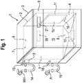
- FIG. 1 shows a schematic spatial representation of an embodiment of a dishwasher 1 according to the invention.
- This has a washing container 2, which is arranged in the interior of a housing 3 of the dishwasher 1.
- the washing compartment 2 comprises a first side wall 4, a second side wall 5, a rear wall 6, a top wall 7 and a floor pan 8.
- Its walls 4, 5, 6, 7 are preferably made of stainless steel sheet.
- the base pan 8 can preferably be a plastic part.
- the washing container 2 is used in particular to hold items to be washed while carrying out a washing cycle for cleaning and / or drying the same.
- it has a cuboid geometry with a loading opening arranged at the front.
- the loading opening provided on the front of the washing compartment 2 can be closed by a door 9, so that an interior 10 of the washing compartment 2, which is also called a washing compartment 10, is essentially closed when the door 9 is closed.
- a water container 11 is arranged on the first side wall 4 of the washing compartment 2, shown on the right, in such a way that it is in thermal contact with the Rinse tank 2 is standing.
- the water tank 11 could also be arranged on the second side wall 5, on the rear wall 6, on the ceiling wall 7 or on the bottom wall 8 and thermally connected to the washing tank.
- one side of the water container 11 lies flush against the washing container 2.
- a filling valve 12 is provided as the filling device, the outlet of which via a valve Figure 1 Not shown line is connected to the water tank 11.
- the inlet of the filling valve 12 is connected to an inlet connection 13 arranged on the housing 3.
- the inlet connection 13 itself is connected via a preferably flexible inlet hose 14 to a water tap WH of a building-side cold water supply WH. In this way, it is possible to fill the water container 11 with water from the cold water supply WH on the building side, which typically has a temperature in the range from 10 ° C. to 20 ° C.
- This temperature of this water is generally below the temperature of the rinsing container 2 while a drying cycle is being carried out, so that a condensation surface 15 on the inside of the rinsing container 2 can be cooled by filling the water container 11 with water from the cold water installation WH on the building side.
- the coolable condensation surface 15 lies opposite the contact surface of the water container 11 on the washing container 2.
- the cooling of the condensation surface 15 can be promoted by thermally conductive properties of the material of the washing container 2, which is why the formation of the condensation surface 15 on a section of the washing container 2 made of stainless steel sheet is expedient.
- a drain valve 16 is provided as an emptying device, which makes it possible to drain the water in the water tank 11 into the rinsing chamber 10, where it can collect in a pump pot 17 integrated in the floor pan 8.
- a pump pot 17 integrated in the floor pan 8.
- the circulating pump is used to apply wash liquid to the wash ware, which can be formed using water, for example from the water tank 11.
- the drain pump serves to pump out a flushing liquid that is no longer required, for example dirty.
- their output is connected to a drain connection 18 arranged on the housing 3, which in turn is connected via a preferably flexible sewage hose 19 to a sewage pipe A installed on the building side.
- the dishwasher 1 also has a sequence control device 20, in which at least one intended sequence, in particular a dishwasher program, is stored for a wash cycle.
- the sequence control device 20 is in the exemplary embodiment of FIG Figure 1 arranged inside the door 9 of the washing compartment 2. However, it could also be arranged at another location, such as, for example, the base assembly of the dishwasher 1.
- An operator interface 21 is also arranged in the area of the door 9, which enables an input unit for inputting operating commands and an output unit for outputting information. However, the operating interface 21 could also be arranged at a different location on the dishwasher 1.
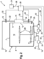
- FIG Figure 2 shows a more detailed representation of the functional components of the dishwasher 1 of FIG Figure 1 in schematic form.
- the filling valve 12 is connected via a connecting line 22 to the water tank 11 in such a way that it can be filled with water when the filling valve 12 is open.
- a return suction protection for example a pipe interruption, and / or a water treatment system, for example a softening and / or desalination system, can be provided in the connecting line 22.
- the filling valve 12 can be controlled by the sequence control device 20, for which purpose a control line 23 is provided, which is used to transmit control commands from the sequence control device 20 to the filling valve 12.
- Another control line 24 is used to transmit control commands from the sequence control device 20 to the drain valve 16 of the water container, so that the drain valve 16 can also be controlled by the flow control device 20.
- water located in the water tank 11 can be introduced into the washing chamber 10 in a controlled manner as required via the drain valve 16 and an outlet 25 adjoining it downstream.
- a circulation pump 26 An input side of a circulation pump 26 is connected to the pump pot 17 in a liquid-conducting manner.
- the circulating pump 26 enables flushing liquid from the pump bowl 17 via a heating device 27 and a spray device 28 arranged in the flushing chamber 10, in particular one or more rotating spray arms, into the Spray rinsing chamber 10 so as to treat items to be washed therein.
- the circulation pump 26 can be controlled, in particular controlled or regulated, with respect to its speed via a control line 29 by the sequence control device 20.
- the heating device 27 can also be adjusted, in particular controlled or regulated, by the sequence control device 20 via a further control line 30.
- a drain pump 31 is connected to the pump pot 17 in a liquid-conducting manner.
- the outlet side of the drain pump 31 is connected via a connecting line 32 to the drain connection 18 fixed to the housing, so that flushing liquid which is no longer required can be pumped out.
- the drain pump 31 can be controlled, in particular controlled or regulated, by the sequence control device 20 via a control line 33.
- the dishwasher 1 can comprise a sensor 34 which is designed to detect a parameter influencing a drying process of the wash ware.
- Figure 2 shows for example a sensor 34 which detects the temperature of the water in the water tank 11. This sensor 34 is connected via a signal line 35 to the sequence control device 20, which is designed to take into account the signals from the sensor 34 when controlling the fill level of the water container 11 at least during the drying cycle of a rinse cycle.
- the sequence control device 20 which is designed to take into account the signals from the sensor 34 when controlling the fill level of the water container 11 at least during the drying cycle of a rinse cycle.
- one or more sensors can be used to measure a temperature of the condensation surface 15, to measure an air temperature in the washing compartment 2, to measure an air humidity in the washing compartment 2, and / or to measure an amount, mass and / or a type of the the washware 2 can be provided.
- control lines 23, 24, 29, 30, 33 and the signal line 35 are used for unidirectional information transmission
- control and signal line 36 which the sequence control device 20 and the user interface 21 connects, preferably provided for bidirectional information transmission, which is also illustrated by corresponding arrows.
- operating commands can be transmitted from the operating interface 21 to the sequence control device 20 and operating information from the sequence control device 20 to the operating interface 21.
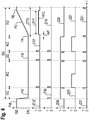
- Figure 3 shows an example of a sequence of a rinse cycle SG controlled by the sequence control device 20.
- the rinse cycle comprises a pre-rinse cycle VG, a cleaning cycle RG, an intermediate rinse cycle ZG, a rinse cycle KG and a drying cycle TG.
- a curve FS shows the fill level of the water tank 11 with water, a curve Z12 the operating state of the filling valve 12, a curve Z16 the operating state of the drain valve 16, a curve Z26 the operating state of the circulation pump 26, a curve Z27 the operating state of the Heating device 27 and a curve Z31 the operating state of the drain pump 31.
- the curve FS shows the fill level of the water tank 11 relative to a design-related maximum fill level FM in percent.
- the maximum fill level FM is reached when the entire volume of the water tank is filled with water.
- curves Z12 and Z16 taking the value “1” corresponds to an open valve and taking the value "0" to a closed valve.
- curves Z26, Z27 and Z31 the value "1" corresponds to an on state and the value "0" corresponds to an off state of the respective device.
- the water tank 11 is completely filled with water from a previous wash cycle, not shown, so that the curve FS assumes the value "100%".
- the water used to cool the condensation surface 15 during the previous wash cycle is introduced into the wash chamber 10 by briefly opening the drain valve 16 at the beginning of the first wash cycle partial wash cycle VG, in the example at the beginning of the pre-wash cycle VG, and circulated there as wash liquid by means of the circulation pump 26.
- the water stored in the storage container assumes room temperature, i.e. it has VG room temperature at the start of the pre-wash cycle, which is usually above the temperature of the building's cold water supply WH lies. For this reason A higher cleaning effect of the pre-rinse cycle VG can be achieved without having to switch on the heating device 27. If, however, a higher temperature is desired for the pre-rinse cycle VG, at least the heating energy required for the heating device then connected can be reduced. It is advantageous if the amount of water in the water tank corresponds exactly to the water requirement of the pre-rinse cycle VG. Alternatively, it would also be possible to use the water used to cool the condensation surface 15 during the previous rinse in a later partial rinse of the rinse.
- the circulation pump 26 is switched off and the drain pump 31 is switched on in order to pump off the now dirty washing liquid.
- the rinsing chamber is supplied with clean water from the cold water supply WH by simultaneously opening the filling valve 12 and the drain valve 16 of the water container 11.
- the circulation pump 26 and the heating device 27 are also switched on at the beginning of the cleaning cycle RG.
- the heating device 27 is switched off again.
- the temperature of the rinsing liquid can be measured with a sensor, not shown, e.g. on or in the rinsing container.
- the circulation pump 26 remains switched on for a so-called post-washing phase in order to continue cleaning the wash ware.
- the circulation pump 26 is also switched off and the drain pump 31 is switched on in order to pump out the now dirty rinsing liquid from the cleaning cycle RG.
- intermediate rinse cycle ZG is analogous to the cleaning cycle RG, although the heater 27 can generally not be switched on.
- the drain pump 31 is switched on in order to pump out as large an amount of the hot rinse aid liquid that drips from the wash ware early on from the dishwasher 1, so as to reduce the evaporation of rinse aid liquid and steam formation in the wash container, so that the drying effect can be increased.
- This switch-on state of the drain pump is in the Figure 3 plotted in the drain curve Z31 of the drain pump and labeled LPA.
- a short dripping phase AP may be provided at the beginning of the drying cycle TG, which serves to drain a substantial part of the rinse aid adhering to the items to be washed before the water container is filled with water the cold water supply takes place. If the filling of the water container with water is only started after this draining phase, the heating of the water in the water container 11 can be reduced over the entire time period ZTG of the drying cycle TG, which benefits the drying efficiency.
- the filling level FS of the water container 11 is gradually increased from an initial filling level FA to a final filling level FE.
- the initial fill level FA essentially corresponds to that of an empty water container.
- the final fill level FE is reached in the water tank 11 when it is essentially filled with water up to its maximum fill level or maximum level FM, ie the fill volume of the water tank is then essentially completely filled with water.
- the several filling phases FP1, FP2, FP3, viewed in accumulation extend over a substantial part of the duration ZTG of the drying cycle TG, whereby a substantial part is understood to mean at least 10%.
- the multiple filling phases occur in total extend over at least 20%, preferably over at least 40%, particularly preferably over at least 60%, and most preferably over at least 80%, of the duration ZTG of the drying cycle TG.
- the filling of the water container 11 starts at the beginning of the drying cycle TG after waiting for an initial dripping phase AP with the first partial filling phase FP1, by means of which the water level in the washing container 11 is partially filled from the level 0% to the level or partial filling level F1 with a partial filling quantity S1.
- This fill level F1 lies above the initial fill level FA of the water container 11 and here so far below the maximum fill level FE that two approximately equal partial fill quantities S2, S3, each corresponding approximately to the first partial fill quantity S1, can be filled until the maximum fill level FE is reached.
- This first filling phase FP1 is followed by two further partial filling phases FP2, FP3 at intervals or pauses P1, P2, during which the partial quantities S2, S3 are supplied to the water tank 11 step by step, ie in portions, by means of the filling valve 12.
- the overall filling process ends when the final filling level FE of the water container 11 is finally reached after the third filling of the partial filling quantity S3.
- the filling valve is designed as a shut-off valve which only has an open state and a closed state.
- the temporal extension i.e. the temporal distribution of the filling of the water container 11 brings about an evening of the cooling of the condensation surface 15, so that the desired condensation of water vapor can be achieved over a longer period of time without the cooling of the condensation surface 15 caused by the water container being filled with a too strong one Cooling of the wash chamber 10 and thus the wash ware would be effected, which would be detrimental to the evaporation of the wash liquid adhering to the wash ware, because the inherent heat stored in the wash ware during the previous rinse cycle would be removed too much and would no longer be sufficient for sufficient evaporation of the moisture on the wash ware. Overall, the drying efficiency can be improved.
- the time stretching of the filling of the water container is caused by dividing the filling process during the drying period ZTG into three partial filling phases FP1, FP2, FP3, during which the water container 11 has multiple stages with the partial filling quantities S1, S2, S3 at intervals or breaks P1, P2 is filled from each other.
- two intermediate levels F1, F2 are therefore provided between the initial level FA and the final level FE.
- the fill level After completion of the first fill level SU1, the fill level reaches a first intermediate fill level F1, after completion of the second stage SU2 a second intermediate fill level F2 and after completion of the third stage SU3 the final state FE. It goes without saying that only two filling stages or even further stages, in particular more than three filling stages, could be provided in further partial filling phases.
- the first stage SU1 serves to cool the condensation surface 15 in an early phase of the drying cycle TG in order to promote the condensation of water vapor.
- the first intermediate fill level F1 is only 40% of the maximum fill level FM in the exemplary embodiment, the rinsing chamber is cooled comparatively little.
- the second stage SU2 is used to compensate for a decrease in cooling which results from the heating of the water filled in the first stage SU1 as the drying cycle progresses.
- the third stage SU3 also serves to compensate for decreasing cooling.
- the temporal distribution of the stages SU1, SU2, SU3, the pauses or waiting times between these, during which no water is supplied to the water tank 11, and the partial filling quantities S1, S2, S3 of the stages SU1, SU2, SU3 can be predetermined or can be controlled using the signals from the sensor 34.
- the same partial filling phases or partial filling times, the same pause times it may also be expedient if one or more of these parameters are set variably or differently.
- the sequence control device 20 can in particular be carried out adaptively by the sequence control device 20, possibly with the aid of at least one sensor for determining one or more factors or parameters influencing the condensation effect.
- the residual amount of the rinsing liquid collected in the pump pot 17 is removed using the Pumped up drain pump 31, which can be composed, for example, of dripping water and condensed water.
- This draining phase is identified in the curve Z31 as the switch-on state and is referred to as LPE.
- Figure 4 shows a further course of a rinse cycle SG, the one compared to the rinse cycle SG Figure 3 modified drying cycle TG 'and does not belong to the invention.
- the modification compared to the time-discrete, successive partial filling of the exemplary embodiment of Figure 3 consists in that a single continuous filling phase FPC with a continuous or continuous filling of the water container 11 is provided during a filling time period ZFP over almost the entire time period ZTG of the drying cycle TG '. This starts after the drip-off phase AP and only ends shortly before the end of the drying process when the water tank has reached its maximum fill level FE.
- the water tank 11 is filled with a filling speed which is substantially lower than that of the partial filling phases FP1, FP2, FP3.
- This reduction or throttling of the filling speed is shown in the example of Figure 4 achieved in that the filling valve 12 is only partially opened, which is shown by the curve Z12 'for the filling valve 12 assuming a value during the filling phase FPC which lies between the value "1" and the value "0".
- the filling valve is expediently designed as a control valve whose through-flow cross section or, more generally, the throughflow rate is adjustable.
- the continuous filling of the water tank here in the exemplary embodiment is carried out by means of the filling valve in such a way that the filling level curve FC for the water level in the water tank between the starting filling level AC and the final filling level FE increases essentially continuously, in particular largely linearly.
- a suitable filling speed could, however, also be achieved by throttling the supplied water flow in another way, for example by reducing the cross-section of the connecting line 22, a bypass being provided for filling the rinsing container 11 with water directly absorbed by the cold water supply, for example during the cleaning cycle RG can, in order to be able to fill the washing container quickly.
- a dishwasher with a water container acting as a heat exchanger can be used in this way, in which by filling the heat exchanger according to the invention in several stages or alternatively and not part of the invention largely continuously over the entire drying period, preventing excessive cooling of the interior of the rinsing container and still producing a sufficiently cool condensation surface can be generated.
- the drying process can be controlled in particular as a function of temperature and / or load (in particular the load quantity, type of load), for example by using one or more sensors. In many cases, energy can be advantageously saved by lowering the rinse aid temperature with the same drying performance.
- the condensation performance of the condensation surface can be adapted to the respectively present one or more parameters during the drying cycle which influence the drying effect of the condensation surface.
- These parameters can include, for example, the inlet temperature of the incoming cold water, the size of the condensation surface, the temperature of the wash ware to be dried, the temperature in the wash tank, material properties of the water tank and / or wash tank and / or, feed lines, the amount of water on the wash ware after the preceding liquid-carrying wash cycle , the filling volume of the water container and / or the rinsing container, the temperature of the rinse cycle preceding the drying cycle, etc., etc.
- the water container is filled in portions, ie through successive successive, time-delayed partial filling cycles.
- several degrees of freedom are provided, with which an improved setting of the cooling capacity of the water container with regard to the condensation surface in thermal contact with it is specifically adapted to the prevailing circumstances, e.g. due to the respectively selected dishwasher program, the type of construction of the dishwasher, etc Vietnamese are given, is made possible.
- the cooling capacity of the water tank can therefore be flexibly adapted to different operating parameters.
Landscapes
- Washing And Drying Of Tableware (AREA)
- Basic Packing Technique (AREA)
Priority Applications (1)
| Application Number | Priority Date | Filing Date | Title |
|---|---|---|---|
| PL10172921T PL2289388T3 (pl) | 2009-08-31 | 2010-08-16 | Zmywarka do naczyń ze zbiornikiem wody do suszenia kondensacyjnego i powiązany sposób napełniania |
Applications Claiming Priority (1)
| Application Number | Priority Date | Filing Date | Title |
|---|---|---|---|
| DE102009029039A DE102009029039A1 (de) | 2009-08-31 | 2009-08-31 | Geschirrspülmaschine mit einem Wasserbehälter zur Kondensationstrocknung sowie zugehöriges Füllverfahren |
Publications (3)
| Publication Number | Publication Date |
|---|---|
| EP2289388A2 EP2289388A2 (de) | 2011-03-02 |
| EP2289388A3 EP2289388A3 (de) | 2017-01-11 |
| EP2289388B1 true EP2289388B1 (de) | 2020-03-11 |
Family
ID=43415343
Family Applications (1)
| Application Number | Title | Priority Date | Filing Date |
|---|---|---|---|
| EP10172921.8A Active EP2289388B1 (de) | 2009-08-31 | 2010-08-16 | Geschirrspülmaschine mit einem Wasserbehälter zur Kondensationstrocknung sowie zugehöriges Füllverfahren |
Country Status (3)
| Country | Link |
|---|---|
| EP (1) | EP2289388B1 (pl) |
| DE (1) | DE102009029039A1 (pl) |
| PL (1) | PL2289388T3 (pl) |
Families Citing this family (3)
| Publication number | Priority date | Publication date | Assignee | Title |
|---|---|---|---|---|
| CN103096778B (zh) | 2010-03-18 | 2016-07-06 | 伊莱克斯家用产品公司 | 用水填充洗碗机的洗涤盆的方法 |
| DE102013109226A1 (de) * | 2013-08-26 | 2015-02-26 | Stefan Borchert | Vorrichtung und Verfahren zum Einsparen von Heizstrom bei einem Haushaltsgerät |
| WO2015167574A1 (en) | 2014-05-02 | 2015-11-05 | Electrolux Home Products, Inc. | Methods, systems, and apparatuses for performing a quick cycle in a dishwasher |
Family Cites Families (5)
| Publication number | Priority date | Publication date | Assignee | Title |
|---|---|---|---|---|
| DE19812230A1 (de) * | 1998-03-20 | 1999-09-23 | Aeg Hausgeraete Gmbh | Geschirrspülmaschine und Verfahren zum Betreiben derselben |
| DE50004697D1 (de) * | 1999-05-26 | 2004-01-22 | Miele & Cie | Programmgesteuerte Geschirrspülmaschine mit einer Einrichtung zum Trocknen von Geschirr |
| DE10023346A1 (de) * | 2000-05-12 | 2001-11-15 | Diehl Ako Stiftung Gmbh & Co | Vorrichtung zum Trocknen von Geschirr in einer Geschirrspülmaschine |
| DE10053030B4 (de) * | 2000-10-26 | 2006-03-16 | Miele & Cie. Kg | Verfahren zur Erkennung der Beladung einer programmgesteuerten Geschirrspülmaschine und Geschirrspülmaschine zur Durchführung des Verfahrens |
| JP2003235781A (ja) * | 2002-02-19 | 2003-08-26 | Matsushita Electric Ind Co Ltd | 食器洗い乾燥機 |
-
2009
- 2009-08-31 DE DE102009029039A patent/DE102009029039A1/de not_active Withdrawn
-
2010
- 2010-08-16 PL PL10172921T patent/PL2289388T3/pl unknown
- 2010-08-16 EP EP10172921.8A patent/EP2289388B1/de active Active
Non-Patent Citations (1)
| Title |
|---|
| None * |
Also Published As
| Publication number | Publication date |
|---|---|
| EP2289388A3 (de) | 2017-01-11 |
| DE102009029039A1 (de) | 2011-03-03 |
| PL2289388T3 (pl) | 2020-08-24 |
| EP2289388A2 (de) | 2011-03-02 |
Similar Documents
| Publication | Publication Date | Title |
|---|---|---|
| EP2482702B1 (de) | Geschirrspülmaschine mit einem flottenspeicher sowie zugehöriges verfahren | |
| EP3261509B1 (de) | Haushalts-geschirrspülmaschine zum waschen von spülgut in ein oder mehreren teilspülgängen sowie zugehöriges verfahren | |
| EP2292133B1 (de) | Geschirrspülmaschine und verfahren zur durchführung eines spülgangs mit einer geschirrspülmaschine | |
| EP2322072B1 (de) | Geschirrspüler mit Latentwärmespeicher | |
| WO2010009890A1 (de) | Geschirrspülmaschine mit zwei umwälzkreisläufen | |
| EP2420175B1 (de) | Geschirrspülmaschine mit einem manuell anpassbaren Spülprogramm | |
| EP2292138B1 (de) | Geschirrspülmaschine | |
| EP2292132A2 (de) | Geschirrspülmaschine sowie zugehöriges Steuerverfahren | |
| EP3021729B1 (de) | Geschirrspülmaschine mit einem in einem wasserbehälter integrierten abflussrohrleitungsabschnitt | |
| EP2473085B1 (de) | Geschirrspülmaschine mit vorratsbehälter sowie zugehöriges vorheizverfahren | |
| EP2440104B1 (de) | Geschirrspülmaschine mit zwei wasseranschlüssen sowie steuerungsverfahren | |
| EP3021731B1 (de) | Geschirrspülmaschine und verfahren zum betrieb einer geschirrspülmaschine mit einem in einem wasserbehälter integrierten abflussrohrleitungsabschnitt | |
| EP2440107A1 (de) | Geschirrspülmaschine mit wärmetauscher sowie zugehöriges steuerungsverfahren | |
| EP2301409A1 (de) | Geschirrspüler mit Sorptionsmedium und Frischluftzufuhr | |
| DE102004060947A1 (de) | Haushalts-Geschirrspülmaschine und Verfahren zum Betreiben derselben | |
| DE102013204003A1 (de) | Geschirrspülmaschine mit einer Sorptionstrockenvorrichtung und einer Öffnungseinrichtung für ihre Tür | |
| EP2353486B1 (de) | Trocknungsmodul für eine Geschirrspülmaschine | |
| EP2228001A1 (de) | Geschirrspülmaschine | |
| EP2289388B1 (de) | Geschirrspülmaschine mit einem Wasserbehälter zur Kondensationstrocknung sowie zugehöriges Füllverfahren | |
| EP2868251B1 (de) | Geschirrspüler mit Startaufschub | |
| EP2919637A1 (de) | Geschirrspülmaschine mit einer mehrkammerigen speichereinrichtung für spülflotte | |
| EP2315546B1 (de) | Geschirrspülmaschine mit zwei umwälzkreisläufen | |
| DE102009001584A1 (de) | Geschirrspülmaschine mit einem Frischwasserspeicher | |
| EP3021728B1 (de) | Geschirrspülmaschine mit einem in einem wasserbehälter integrierten abflussrohrleitungsabschnitt | |
| EP2420174A2 (de) | Geschirrspülmaschine mit einer verbesserten Abpumpsequenz |
Legal Events
| Date | Code | Title | Description |
|---|---|---|---|
| PUAI | Public reference made under article 153(3) epc to a published international application that has entered the european phase |
Free format text: ORIGINAL CODE: 0009012 |
|
| AK | Designated contracting states |
Kind code of ref document: A2 Designated state(s): AL AT BE BG CH CY CZ DE DK EE ES FI FR GB GR HR HU IE IS IT LI LT LU LV MC MK MT NL NO PL PT RO SE SI SK SM TR |
|
| AX | Request for extension of the european patent |
Extension state: BA ME RS |
|
| RAP1 | Party data changed (applicant data changed or rights of an application transferred) |
Owner name: BSH HAUSGERAETE GMBH |
|
| PUAL | Search report despatched |
Free format text: ORIGINAL CODE: 0009013 |
|
| AK | Designated contracting states |
Kind code of ref document: A3 Designated state(s): AL AT BE BG CH CY CZ DE DK EE ES FI FR GB GR HR HU IE IS IT LI LT LU LV MC MK MT NL NO PL PT RO SE SI SK SM TR |
|
| AX | Request for extension of the european patent |
Extension state: BA ME RS |
|
| RIC1 | Information provided on ipc code assigned before grant |
Ipc: A47L 15/42 20060101AFI20161206BHEP Ipc: A47L 15/48 20060101ALI20161206BHEP |
|
| STAA | Information on the status of an ep patent application or granted ep patent |
Free format text: STATUS: REQUEST FOR EXAMINATION WAS MADE |
|
| 17P | Request for examination filed |
Effective date: 20170711 |
|
| RBV | Designated contracting states (corrected) |
Designated state(s): AL AT BE BG CH CY CZ DE DK EE ES FI FR GB GR HR HU IE IS IT LI LT LU LV MC MK MT NL NO PL PT RO SE SI SK SM TR |
|
| GRAP | Despatch of communication of intention to grant a patent |
Free format text: ORIGINAL CODE: EPIDOSNIGR1 |
|
| STAA | Information on the status of an ep patent application or granted ep patent |
Free format text: STATUS: GRANT OF PATENT IS INTENDED |
|
| INTG | Intention to grant announced |
Effective date: 20190220 |
|
| GRAJ | Information related to disapproval of communication of intention to grant by the applicant or resumption of examination proceedings by the epo deleted |
Free format text: ORIGINAL CODE: EPIDOSDIGR1 |
|
| STAA | Information on the status of an ep patent application or granted ep patent |
Free format text: STATUS: REQUEST FOR EXAMINATION WAS MADE |
|
| INTC | Intention to grant announced (deleted) | ||
| GRAP | Despatch of communication of intention to grant a patent |
Free format text: ORIGINAL CODE: EPIDOSNIGR1 |
|
| STAA | Information on the status of an ep patent application or granted ep patent |
Free format text: STATUS: GRANT OF PATENT IS INTENDED |
|
| INTG | Intention to grant announced |
Effective date: 20191028 |
|
| GRAS | Grant fee paid |
Free format text: ORIGINAL CODE: EPIDOSNIGR3 |
|
| GRAA | (expected) grant |
Free format text: ORIGINAL CODE: 0009210 |
|
| STAA | Information on the status of an ep patent application or granted ep patent |
Free format text: STATUS: THE PATENT HAS BEEN GRANTED |
|
| AK | Designated contracting states |
Kind code of ref document: B1 Designated state(s): AL AT BE BG CH CY CZ DE DK EE ES FI FR GB GR HR HU IE IS IT LI LT LU LV MC MK MT NL NO PL PT RO SE SI SK SM TR |
|
| REG | Reference to a national code |
Ref country code: GB Ref legal event code: FG4D Free format text: NOT ENGLISH |
|
| REG | Reference to a national code |
Ref country code: CH Ref legal event code: EP |
|
| REG | Reference to a national code |
Ref country code: AT Ref legal event code: REF Ref document number: 1242105 Country of ref document: AT Kind code of ref document: T Effective date: 20200315 |
|
| REG | Reference to a national code |
Ref country code: IE Ref legal event code: FG4D Free format text: LANGUAGE OF EP DOCUMENT: GERMAN |
|
| REG | Reference to a national code |
Ref country code: DE Ref legal event code: R096 Ref document number: 502010016523 Country of ref document: DE |
|
| PG25 | Lapsed in a contracting state [announced via postgrant information from national office to epo] |
Ref country code: NO Free format text: LAPSE BECAUSE OF FAILURE TO SUBMIT A TRANSLATION OF THE DESCRIPTION OR TO PAY THE FEE WITHIN THE PRESCRIBED TIME-LIMIT Effective date: 20200611 Ref country code: FI Free format text: LAPSE BECAUSE OF FAILURE TO SUBMIT A TRANSLATION OF THE DESCRIPTION OR TO PAY THE FEE WITHIN THE PRESCRIBED TIME-LIMIT Effective date: 20200311 |
|
| REG | Reference to a national code |
Ref country code: NL Ref legal event code: MP Effective date: 20200311 |
|
| PG25 | Lapsed in a contracting state [announced via postgrant information from national office to epo] |
Ref country code: GR Free format text: LAPSE BECAUSE OF FAILURE TO SUBMIT A TRANSLATION OF THE DESCRIPTION OR TO PAY THE FEE WITHIN THE PRESCRIBED TIME-LIMIT Effective date: 20200612 Ref country code: LV Free format text: LAPSE BECAUSE OF FAILURE TO SUBMIT A TRANSLATION OF THE DESCRIPTION OR TO PAY THE FEE WITHIN THE PRESCRIBED TIME-LIMIT Effective date: 20200311 Ref country code: SE Free format text: LAPSE BECAUSE OF FAILURE TO SUBMIT A TRANSLATION OF THE DESCRIPTION OR TO PAY THE FEE WITHIN THE PRESCRIBED TIME-LIMIT Effective date: 20200311 Ref country code: HR Free format text: LAPSE BECAUSE OF FAILURE TO SUBMIT A TRANSLATION OF THE DESCRIPTION OR TO PAY THE FEE WITHIN THE PRESCRIBED TIME-LIMIT Effective date: 20200311 Ref country code: BG Free format text: LAPSE BECAUSE OF FAILURE TO SUBMIT A TRANSLATION OF THE DESCRIPTION OR TO PAY THE FEE WITHIN THE PRESCRIBED TIME-LIMIT Effective date: 20200611 |
|
| REG | Reference to a national code |
Ref country code: LT Ref legal event code: MG4D |
|
| PG25 | Lapsed in a contracting state [announced via postgrant information from national office to epo] |
Ref country code: NL Free format text: LAPSE BECAUSE OF FAILURE TO SUBMIT A TRANSLATION OF THE DESCRIPTION OR TO PAY THE FEE WITHIN THE PRESCRIBED TIME-LIMIT Effective date: 20200311 |
|
| PG25 | Lapsed in a contracting state [announced via postgrant information from national office to epo] |
Ref country code: EE Free format text: LAPSE BECAUSE OF FAILURE TO SUBMIT A TRANSLATION OF THE DESCRIPTION OR TO PAY THE FEE WITHIN THE PRESCRIBED TIME-LIMIT Effective date: 20200311 Ref country code: LT Free format text: LAPSE BECAUSE OF FAILURE TO SUBMIT A TRANSLATION OF THE DESCRIPTION OR TO PAY THE FEE WITHIN THE PRESCRIBED TIME-LIMIT Effective date: 20200311 Ref country code: CZ Free format text: LAPSE BECAUSE OF FAILURE TO SUBMIT A TRANSLATION OF THE DESCRIPTION OR TO PAY THE FEE WITHIN THE PRESCRIBED TIME-LIMIT Effective date: 20200311 Ref country code: RO Free format text: LAPSE BECAUSE OF FAILURE TO SUBMIT A TRANSLATION OF THE DESCRIPTION OR TO PAY THE FEE WITHIN THE PRESCRIBED TIME-LIMIT Effective date: 20200311 Ref country code: SK Free format text: LAPSE BECAUSE OF FAILURE TO SUBMIT A TRANSLATION OF THE DESCRIPTION OR TO PAY THE FEE WITHIN THE PRESCRIBED TIME-LIMIT Effective date: 20200311 Ref country code: PT Free format text: LAPSE BECAUSE OF FAILURE TO SUBMIT A TRANSLATION OF THE DESCRIPTION OR TO PAY THE FEE WITHIN THE PRESCRIBED TIME-LIMIT Effective date: 20200805 Ref country code: IS Free format text: LAPSE BECAUSE OF FAILURE TO SUBMIT A TRANSLATION OF THE DESCRIPTION OR TO PAY THE FEE WITHIN THE PRESCRIBED TIME-LIMIT Effective date: 20200711 Ref country code: SM Free format text: LAPSE BECAUSE OF FAILURE TO SUBMIT A TRANSLATION OF THE DESCRIPTION OR TO PAY THE FEE WITHIN THE PRESCRIBED TIME-LIMIT Effective date: 20200311 |
|
| REG | Reference to a national code |
Ref country code: DE Ref legal event code: R097 Ref document number: 502010016523 Country of ref document: DE |
|
| PLBE | No opposition filed within time limit |
Free format text: ORIGINAL CODE: 0009261 |
|
| STAA | Information on the status of an ep patent application or granted ep patent |
Free format text: STATUS: NO OPPOSITION FILED WITHIN TIME LIMIT |
|
| PG25 | Lapsed in a contracting state [announced via postgrant information from national office to epo] |
Ref country code: ES Free format text: LAPSE BECAUSE OF FAILURE TO SUBMIT A TRANSLATION OF THE DESCRIPTION OR TO PAY THE FEE WITHIN THE PRESCRIBED TIME-LIMIT Effective date: 20200311 Ref country code: DK Free format text: LAPSE BECAUSE OF FAILURE TO SUBMIT A TRANSLATION OF THE DESCRIPTION OR TO PAY THE FEE WITHIN THE PRESCRIBED TIME-LIMIT Effective date: 20200311 Ref country code: IT Free format text: LAPSE BECAUSE OF FAILURE TO SUBMIT A TRANSLATION OF THE DESCRIPTION OR TO PAY THE FEE WITHIN THE PRESCRIBED TIME-LIMIT Effective date: 20200311 |
|
| 26N | No opposition filed |
Effective date: 20201214 |
|
| PG25 | Lapsed in a contracting state [announced via postgrant information from national office to epo] |
Ref country code: SI Free format text: LAPSE BECAUSE OF FAILURE TO SUBMIT A TRANSLATION OF THE DESCRIPTION OR TO PAY THE FEE WITHIN THE PRESCRIBED TIME-LIMIT Effective date: 20200311 |
|
| PG25 | Lapsed in a contracting state [announced via postgrant information from national office to epo] |
Ref country code: MC Free format text: LAPSE BECAUSE OF FAILURE TO SUBMIT A TRANSLATION OF THE DESCRIPTION OR TO PAY THE FEE WITHIN THE PRESCRIBED TIME-LIMIT Effective date: 20200311 |
|
| REG | Reference to a national code |
Ref country code: CH Ref legal event code: PL |
|
| GBPC | Gb: european patent ceased through non-payment of renewal fee |
Effective date: 20200816 |
|
| PG25 | Lapsed in a contracting state [announced via postgrant information from national office to epo] |
Ref country code: LU Free format text: LAPSE BECAUSE OF NON-PAYMENT OF DUE FEES Effective date: 20200816 Ref country code: CH Free format text: LAPSE BECAUSE OF NON-PAYMENT OF DUE FEES Effective date: 20200831 Ref country code: LI Free format text: LAPSE BECAUSE OF NON-PAYMENT OF DUE FEES Effective date: 20200831 |
|
| REG | Reference to a national code |
Ref country code: BE Ref legal event code: MM Effective date: 20200831 |
|
| PG25 | Lapsed in a contracting state [announced via postgrant information from national office to epo] |
Ref country code: FR Free format text: LAPSE BECAUSE OF NON-PAYMENT OF DUE FEES Effective date: 20200831 |
|
| PG25 | Lapsed in a contracting state [announced via postgrant information from national office to epo] |
Ref country code: IE Free format text: LAPSE BECAUSE OF NON-PAYMENT OF DUE FEES Effective date: 20200816 Ref country code: GB Free format text: LAPSE BECAUSE OF NON-PAYMENT OF DUE FEES Effective date: 20200816 Ref country code: BE Free format text: LAPSE BECAUSE OF NON-PAYMENT OF DUE FEES Effective date: 20200831 |
|
| REG | Reference to a national code |
Ref country code: AT Ref legal event code: MM01 Ref document number: 1242105 Country of ref document: AT Kind code of ref document: T Effective date: 20200816 |
|
| PG25 | Lapsed in a contracting state [announced via postgrant information from national office to epo] |
Ref country code: AT Free format text: LAPSE BECAUSE OF NON-PAYMENT OF DUE FEES Effective date: 20200816 |
|
| PG25 | Lapsed in a contracting state [announced via postgrant information from national office to epo] |
Ref country code: MT Free format text: LAPSE BECAUSE OF FAILURE TO SUBMIT A TRANSLATION OF THE DESCRIPTION OR TO PAY THE FEE WITHIN THE PRESCRIBED TIME-LIMIT Effective date: 20200311 Ref country code: CY Free format text: LAPSE BECAUSE OF FAILURE TO SUBMIT A TRANSLATION OF THE DESCRIPTION OR TO PAY THE FEE WITHIN THE PRESCRIBED TIME-LIMIT Effective date: 20200311 |
|
| PG25 | Lapsed in a contracting state [announced via postgrant information from national office to epo] |
Ref country code: MK Free format text: LAPSE BECAUSE OF FAILURE TO SUBMIT A TRANSLATION OF THE DESCRIPTION OR TO PAY THE FEE WITHIN THE PRESCRIBED TIME-LIMIT Effective date: 20200311 Ref country code: AL Free format text: LAPSE BECAUSE OF FAILURE TO SUBMIT A TRANSLATION OF THE DESCRIPTION OR TO PAY THE FEE WITHIN THE PRESCRIBED TIME-LIMIT Effective date: 20200311 |
|
| PGFP | Annual fee paid to national office [announced via postgrant information from national office to epo] |
Ref country code: DE Payment date: 20250831 Year of fee payment: 16 |
|
| PGFP | Annual fee paid to national office [announced via postgrant information from national office to epo] |
Ref country code: PL Payment date: 20250801 Year of fee payment: 16 Ref country code: TR Payment date: 20250808 Year of fee payment: 16 |