EP2289388B1 - Dishwasher with a water container for condensation drying and method for filling same - Google Patents
Dishwasher with a water container for condensation drying and method for filling same Download PDFInfo
- Publication number
- EP2289388B1 EP2289388B1 EP10172921.8A EP10172921A EP2289388B1 EP 2289388 B1 EP2289388 B1 EP 2289388B1 EP 10172921 A EP10172921 A EP 10172921A EP 2289388 B1 EP2289388 B1 EP 2289388B1
- Authority
- EP
- European Patent Office
- Prior art keywords
- filling
- water
- cycle
- water tank
- dishwasher
- Prior art date
- Legal status (The legal status is an assumption and is not a legal conclusion. Google has not performed a legal analysis and makes no representation as to the accuracy of the status listed.)
- Active
Links
- XLYOFNOQVPJJNP-UHFFFAOYSA-N water Substances O XLYOFNOQVPJJNP-UHFFFAOYSA-N 0.000 title claims description 241
- 238000011049 filling Methods 0.000 title claims description 182
- 238000001035 drying Methods 0.000 title claims description 140
- 238000009833 condensation Methods 0.000 title claims description 58
- 230000005494 condensation Effects 0.000 title claims description 58
- 238000000034 method Methods 0.000 title claims description 14
- 238000005406 washing Methods 0.000 claims description 81
- 238000004140 cleaning Methods 0.000 claims description 25
- 239000007788 liquid Substances 0.000 description 43
- 238000001816 cooling Methods 0.000 description 19
- 238000011161 development Methods 0.000 description 19
- 230000018109 developmental process Effects 0.000 description 19
- 238000010438 heat treatment Methods 0.000 description 18
- 230000000694 effects Effects 0.000 description 10
- 238000001704 evaporation Methods 0.000 description 8
- 230000008020 evaporation Effects 0.000 description 8
- 230000002123 temporal effect Effects 0.000 description 6
- 230000008901 benefit Effects 0.000 description 5
- 239000007921 spray Substances 0.000 description 5
- 239000012459 cleaning agent Substances 0.000 description 4
- 230000007423 decrease Effects 0.000 description 4
- 238000013461 design Methods 0.000 description 4
- 238000001514 detection method Methods 0.000 description 4
- 238000005429 filling process Methods 0.000 description 4
- 238000011010 flushing procedure Methods 0.000 description 4
- 230000006872 improvement Effects 0.000 description 4
- 238000011068 loading method Methods 0.000 description 4
- 230000008569 process Effects 0.000 description 4
- 239000010865 sewage Substances 0.000 description 4
- 238000005338 heat storage Methods 0.000 description 3
- 239000000463 material Substances 0.000 description 3
- 230000001105 regulatory effect Effects 0.000 description 3
- 230000005540 biological transmission Effects 0.000 description 2
- 230000015572 biosynthetic process Effects 0.000 description 2
- 238000004851 dishwashing Methods 0.000 description 2
- 238000009826 distribution Methods 0.000 description 2
- 230000005484 gravity Effects 0.000 description 2
- 229910001220 stainless steel Inorganic materials 0.000 description 2
- 239000010935 stainless steel Substances 0.000 description 2
- 235000008733 Citrus aurantifolia Nutrition 0.000 description 1
- 235000011941 Tilia x europaea Nutrition 0.000 description 1
- 238000009825 accumulation Methods 0.000 description 1
- 239000000654 additive Substances 0.000 description 1
- 230000000712 assembly Effects 0.000 description 1
- 238000000429 assembly Methods 0.000 description 1
- 230000009286 beneficial effect Effects 0.000 description 1
- 230000002457 bidirectional effect Effects 0.000 description 1
- 238000010276 construction Methods 0.000 description 1
- 230000001276 controlling effect Effects 0.000 description 1
- 230000003247 decreasing effect Effects 0.000 description 1
- 230000001419 dependent effect Effects 0.000 description 1
- 238000010612 desalination reaction Methods 0.000 description 1
- 230000001627 detrimental effect Effects 0.000 description 1
- 238000005265 energy consumption Methods 0.000 description 1
- 238000009434 installation Methods 0.000 description 1
- 238000009413 insulation Methods 0.000 description 1
- 238000012432 intermediate storage Methods 0.000 description 1
- 239000004571 lime Substances 0.000 description 1
- 239000002184 metal Substances 0.000 description 1
- 230000004048 modification Effects 0.000 description 1
- 238000012986 modification Methods 0.000 description 1
- 238000005457 optimization Methods 0.000 description 1
- 230000009467 reduction Effects 0.000 description 1
- 150000003839 salts Chemical class 0.000 description 1
- 238000005507 spraying Methods 0.000 description 1
- 238000003860 storage Methods 0.000 description 1
- 239000000126 substance Substances 0.000 description 1
- 238000012549 training Methods 0.000 description 1
Images

Classifications
-
- A—HUMAN NECESSITIES
- A47—FURNITURE; DOMESTIC ARTICLES OR APPLIANCES; COFFEE MILLS; SPICE MILLS; SUCTION CLEANERS IN GENERAL
- A47L—DOMESTIC WASHING OR CLEANING; SUCTION CLEANERS IN GENERAL
- A47L15/00—Washing or rinsing machines for crockery or tableware
- A47L15/0018—Controlling processes, i.e. processes to control the operation of the machine characterised by the purpose or target of the control
- A47L15/0021—Regulation of operational steps within the washing processes, e.g. optimisation or improvement of operational steps depending from the detergent nature or from the condition of the crockery
- A47L15/0034—Drying phases, including dripping-off phases
-
- A—HUMAN NECESSITIES
- A47—FURNITURE; DOMESTIC ARTICLES OR APPLIANCES; COFFEE MILLS; SPICE MILLS; SUCTION CLEANERS IN GENERAL
- A47L—DOMESTIC WASHING OR CLEANING; SUCTION CLEANERS IN GENERAL
- A47L15/00—Washing or rinsing machines for crockery or tableware
- A47L15/0018—Controlling processes, i.e. processes to control the operation of the machine characterised by the purpose or target of the control
- A47L15/0021—Regulation of operational steps within the washing processes, e.g. optimisation or improvement of operational steps depending from the detergent nature or from the condition of the crockery
- A47L15/0023—Water filling
-
- A—HUMAN NECESSITIES
- A47—FURNITURE; DOMESTIC ARTICLES OR APPLIANCES; COFFEE MILLS; SPICE MILLS; SUCTION CLEANERS IN GENERAL
- A47L—DOMESTIC WASHING OR CLEANING; SUCTION CLEANERS IN GENERAL
- A47L15/00—Washing or rinsing machines for crockery or tableware
- A47L15/42—Details
- A47L15/4291—Recovery arrangements, e.g. for the recovery of energy or water
-
- A—HUMAN NECESSITIES
- A47—FURNITURE; DOMESTIC ARTICLES OR APPLIANCES; COFFEE MILLS; SPICE MILLS; SUCTION CLEANERS IN GENERAL
- A47L—DOMESTIC WASHING OR CLEANING; SUCTION CLEANERS IN GENERAL
- A47L15/00—Washing or rinsing machines for crockery or tableware
- A47L15/42—Details
- A47L15/48—Drying arrangements
- A47L15/483—Drying arrangements by using condensers
-
- A—HUMAN NECESSITIES
- A47—FURNITURE; DOMESTIC ARTICLES OR APPLIANCES; COFFEE MILLS; SPICE MILLS; SUCTION CLEANERS IN GENERAL
- A47L—DOMESTIC WASHING OR CLEANING; SUCTION CLEANERS IN GENERAL
- A47L2401/00—Automatic detection in controlling methods of washing or rinsing machines for crockery or tableware, e.g. information provided by sensors entered into controlling devices
- A47L2401/04—Crockery or tableware details, e.g. material, quantity, condition
-
- A—HUMAN NECESSITIES
- A47—FURNITURE; DOMESTIC ARTICLES OR APPLIANCES; COFFEE MILLS; SPICE MILLS; SUCTION CLEANERS IN GENERAL
- A47L—DOMESTIC WASHING OR CLEANING; SUCTION CLEANERS IN GENERAL
- A47L2401/00—Automatic detection in controlling methods of washing or rinsing machines for crockery or tableware, e.g. information provided by sensors entered into controlling devices
- A47L2401/12—Water temperature
-
- A—HUMAN NECESSITIES
- A47—FURNITURE; DOMESTIC ARTICLES OR APPLIANCES; COFFEE MILLS; SPICE MILLS; SUCTION CLEANERS IN GENERAL
- A47L—DOMESTIC WASHING OR CLEANING; SUCTION CLEANERS IN GENERAL
- A47L2401/00—Automatic detection in controlling methods of washing or rinsing machines for crockery or tableware, e.g. information provided by sensors entered into controlling devices
- A47L2401/18—Air temperature
-
- A—HUMAN NECESSITIES
- A47—FURNITURE; DOMESTIC ARTICLES OR APPLIANCES; COFFEE MILLS; SPICE MILLS; SUCTION CLEANERS IN GENERAL
- A47L—DOMESTIC WASHING OR CLEANING; SUCTION CLEANERS IN GENERAL
- A47L2401/00—Automatic detection in controlling methods of washing or rinsing machines for crockery or tableware, e.g. information provided by sensors entered into controlling devices
- A47L2401/19—Air humidity
-
- A—HUMAN NECESSITIES
- A47—FURNITURE; DOMESTIC ARTICLES OR APPLIANCES; COFFEE MILLS; SPICE MILLS; SUCTION CLEANERS IN GENERAL
- A47L—DOMESTIC WASHING OR CLEANING; SUCTION CLEANERS IN GENERAL
- A47L2501/00—Output in controlling method of washing or rinsing machines for crockery or tableware, i.e. quantities or components controlled, or actions performed by the controlling device executing the controlling method
- A47L2501/01—Water supply, e.g. opening or closure of the water inlet valve
-
- Y—GENERAL TAGGING OF NEW TECHNOLOGICAL DEVELOPMENTS; GENERAL TAGGING OF CROSS-SECTIONAL TECHNOLOGIES SPANNING OVER SEVERAL SECTIONS OF THE IPC; TECHNICAL SUBJECTS COVERED BY FORMER USPC CROSS-REFERENCE ART COLLECTIONS [XRACs] AND DIGESTS
- Y02—TECHNOLOGIES OR APPLICATIONS FOR MITIGATION OR ADAPTATION AGAINST CLIMATE CHANGE
- Y02B—CLIMATE CHANGE MITIGATION TECHNOLOGIES RELATED TO BUILDINGS, e.g. HOUSING, HOUSE APPLIANCES OR RELATED END-USER APPLICATIONS
- Y02B40/00—Technologies aiming at improving the efficiency of home appliances, e.g. induction cooking or efficient technologies for refrigerators, freezers or dish washers
Definitions
- the present invention relates to a dishwasher, in particular household dishwashing machine, with a washing container for holding items to be washed, with at least one water container which, in heat-conducting contact with the washing container, serves to provide at least one condensation surface of the washing container during at least one drying cycle, and with a filling device for filling the water tank with water.
- a dishwasher with such a water container is known in practice.
- the items to be washed are subjected to a heated rinse liquid in a rinse cycle preceding the drying cycle or drying process and thus heated.
- the washing liquid adhering to the wash ware evaporates, so that the wash ware dries.
- the resulting water vapor then condenses on the inside of the rinsing container.
- the condensation of the water vapor is promoted by a condensation surface, which is cooled by water in the water tank.
- WO 01/85003 A2 describes a device for drying dishes in a washing compartment of a dishwasher.
- the resulting hot, moist washroom air is dehumidified by condensation outside the washroom, the condensate is collected and the dehumidified washroom air is returned to the washroom.
- a heat exchanger is provided which forms a water guiding space on one side of a heat exchanger surface and an air guiding space for washing air on the other side of the heat exchanger surface.
- the heat exchanger surface is arranged in such a way that the moist wash-room air condenses on it and the condensate under gravity into an intermediate store expires, to which the water routing room is connected.
- the water guide space is connected to the intermediate storage via a valve.
- the valve When the valve is closed, cold water is let into the water guide space.
- Hot, moist wash cabinet air is conveyed from the wash cabinet through the air guide space and through an inlet opening back into the wash cabinet in the circuit by means of a circulation fan.
- Condensate condenses on the surface of the heat exchanger and flows under the force of gravity through a gap into the intermediate store, the valve of which is closed to the washing compartment.
- Dehumidified air thus enters the wash cabinet through the inlet opening and supports the further drying of the dishes.
- the temperature difference on the heat exchanger surface inevitably decreases.
- valve is opened and the heated water from the water guide space is released into the intermediate store.
- the valve between the water guide space and the intermediate store is then closed again and fresh cold water is poured into the water guide space, after which the condensation continues.
- the object of the present invention is to provide a dishwasher, in particular a domestic dishwasher, in which the drying efficiency is improved.
- the object is achieved in a dishwasher of the type mentioned at the outset in that the filling device is designed in such a way that the water tank can be filled with water in a number of filling phases over the period of the respective drying cycle.
- the water tank can be filled over the period of the respective drying cycle, i.e. the water tank can be refilled with partial amounts of water during the respective drying cycle, sufficient cooling of the condensation surface of the rinsing tank can be largely ensured over the entire drying process .
- the water tank can be refilled with water in several filling phases, which has a colder temperature than the water already stored in the water tank.
- the condensation effect of the water container on a variety of operating parameters of the dishwasher according to the invention such as the temperature of the incoming water, rinse temperature, amount, type, and / or heat storage capacity, in particular the mass of the wash ware, materials and / or wall thicknesses used for the rinse tank and / or water tank, volume of the water tank and / or the rinse tank, etc. can be customized in a simple and reliable manner. This goes hand in hand with improved drying efficiency.
- the items to be washed in particular dishes to be washed, can be introduced into a washing container and cleaned there in a washing process, which is also called a washing cycle, with the aid of washing liquid and then dried.
- the washing compartment can in particular be composed of sheet metal parts and / or plastic parts, a loading opening for introducing and removing items to be washed being closable by a door, so that the interior of the washing compartment, which is also called the washing compartment, is essentially closed when the door is closed.
- a rinsing liquid also called a rinsing liquor, is understood to be a liquid which is intended to be applied to the items to be washed in order to clean and / or treat them in another way.
- a rinsing liquid usually consists mostly of water.
- the washing liquid can be enriched with cleaning agents, with cleaning aids such as rinse aid and / or with dirt that has been detached from the items to be washed.
- the aim is preferably to carry out a rinse cycle in such a way that a predefined cleaning result and a predefined drying result are achieved as efficiently as possible.
- a high overall efficiency is required, which results from the cleaning efficiency and the drying efficiency.
- the cleaning efficiency corresponds in particular to the ratio of the cleaning result achieved by means of a rinse cycle and the effort required for this, the effort being able to include several dimensions, for example the energy requirement, the water requirement and / or the time requirement.
- the drying efficiency corresponds in particular to the ratio of the drying result achieved by means of a rinse cycle and the effort required for this, the effort also can include several dimensions here, for example the energy requirement and / or the time requirement.
- a sequence control device which automatically controls a wash cycle according to a predetermined sequence.
- a plurality of predefined sequences for a rinse cycle can be stored in the sequence control device, one of which is used to carry out a rinse cycle.
- the selection of a specific sequence can be carried out in particular by an operator.
- an operating interface connected to the sequence control device can be provided, which comprises an input unit for entering operating commands.
- the operator interface can also have an output unit for outputting information to the operator. Possibly.
- a fully automatic selection of a dishwashing program by the sequence control device is also possible.
- the sequence control device is designed in particular in such a way that a rinse cycle can be carried out, which comprises at least one partial rinse cycle for cleaning the washware with the aid of rinsing liquid and at least one partial rinse cycle for drying the washware.
- An envisaged sequence of such a wash cycle provides, for example, a plurality of partial wash cycles for cleaning the wash ware, namely, in particular in this chronological order, a pre-wash cycle, a cleaning cycle, an intermediate rinse cycle and a rinse cycle, in each of which the wash ware is subjected to a washing liquid.
- These partial rinse cycles are therefore referred to as partial rinse cycles carrying rinsing liquid.
- the proposed sequence provides a subsequent partial rinse following the rinsing liquid-carrying partial rinses for drying the cleaned items, namely a drying cycle or drying process.
- processes can also be provided in which one or more of these partial rinse cycles carrying rinsing liquid are hidden. It is also possible to run the rinse cycle in which one or more of these partial rinse cycles are run through several times.
- the pre-rinse cycle is used primarily to remove coarser soiling from the wash ware.
- the purpose of the subsequent cleaning cycle is to completely remove dirt from the items to be washed, for which purpose a washing liquid mixed with cleaning agent can be used.
- the intermediate rinse cycle now carried out serves in particular to remove residues of cleaning agent which adhere to the items to be washed.
- the subsequent rinse cycle is intended, in particular, to avoid stains on the wash ware, which could be caused by dissolved substances in the water, such as salt and / or lime.
- the rinsing liquid can be mixed with rinse aid during the rinse cycle.
- Another task of the final rinse cycle is to prepare the subsequent drying cycle. To do this, the dishes can be heated to a high temperature during the rinse cycle.
- the drying cycle begins when the load on the wash ware is rinsed with the rinse liquid of the last partial rinse cycle carrying rinse liquid, that is to say generally after the wash rinse cycle has been loaded with the rinse liquid. Possibly. it can be initiated with a so-called draining phase, while the liquid is still dripping off the items to be washed and collected at the bottom of the washing container and is preferably pumped out of the washing container with the aid of a drain pump.
- draining phase while the liquid is still dripping off the items to be washed and collected at the bottom of the washing container and is preferably pumped out of the washing container with the aid of a drain pump.
- the end of the drying cycle is determined by the point in time specified by the respective washing program at which the removal of the dishes from the washing container in the dry state is provided as early as possible. This time usually coincides with the time at which the rinse cycle ends.
- the end of the drying cycle and the rinsing cycle as a whole can be communicated to the operator via the user interface.
- the dishwasher according to the invention can have means which can be controlled by the sequence control device and which allow the automatic loading of washware with washing liquid during the partial washing cycles carrying the washing liquid.
- these means can be a circulation pump and comprise at least one spray device arranged in the interior of the washing container, in particular an upper and a lower rotatable spray arm.
- the dishwasher can have a preferably electrical heating device which can be controlled by the sequence control device in order to bring the washing liquids of the individual washing liquid-carrying partial wash cycles to the respectively required temperature.
- the dishwasher can furthermore have a metering device which can be controlled by the sequence control device.
- the dishwasher according to the invention also has at least one water container for holding water, which is in heat-conducting contact with the washing container for providing at least one condensation surface.
- the water tank can be filled with water via a filling device.
- the filling device can in particular be controllable by the sequence control device of the dishwasher, which is used to control at least one wash cycle for cleaning items to be washed. It can preferably be designed as a filling valve that can be controlled by the sequence control device. It is provided to fill the water tank with water over a period of the drying cycle in several filling phases, which can be done by a corresponding control of the filling device, in particular the filling valve.
- the fill level of the water container during the drying cycle is increased from an initial fill level to a final fill level.
- water is therefore refilled into the water tank, so that its water level rises.
- the filling of the water container thus begins, in particular, at the point in time at which its initial fill level is increased and preferably ends at the point in time at which its final fill level is finally reached.
- the aim here is to cool at least one condensation surface provided on an inside of the rinsing container on at least part of its surface.
- the water container can expediently be filled with cold water, in particular from a cold water network, which for example has a temperature of less than 30 ° C, less than 20 ° C or less than 15 ° C.
- a cold water network which for example has a temperature of less than 30 ° C, less than 20 ° C or less than 15 ° C.
- a water tank is also called a cold water bag or heat exchanger.
- the respective water container can in particular lie flat against a side wall or against a rear wall of the rinsing container.
- the coolable condensation surface corresponds to that area of the washing compartment that is in thermal contact with the washing compartment.
- the multiple filling phases extend over a substantial part of the duration of the drying cycle.
- This can preferably be understood to mean that the multiple filling phases as a whole, i.e. accumulated, extend over at least 10% of the duration of the drying cycle.
- cooling of the condensation surface which promotes the condensation of water vapor on the inside of the rinsing container, can be maintained over a longer period of time during the drying cycle than with an initial complete filling of the water container, without the interior of the rinsing container and the inside of it Washware cools down too much, which would reduce the tendency of evaporation of washing liquid adhering to the washware.
- the drying efficiency can be significantly increased.
- excessive cooling of the items to be washed which occurs there in an early phase of the drying cycle, can be avoided, so that the heat of the items to be washed stored during the rinsing cycle and thus the evaporation of the items to be washed over a longer time, in particular largely over the entire duration of the drying cycle, on one high level is maintained.
- the respective duration of the respective filling phase, the total duration of the one or more filling phases, any dead times between several successive filling phases, and / or possibly also the time course of the filling during the respective filling phase can be determined taking into account the structural conditions of the dishwasher. For example, the maximum fill level of the washing container, the thermal insulation of the interior of the washing container with respect to the surroundings and the heat storage capacity of the washing container and its door can be taken into account. However, other parameters of the wash cycle can also be taken into account, for example the initial temperature of the interior of the wash tank, the temperature of the water with which the water tank is filled, and the heat storage capacity of the wash ware.
- the drying efficiency of a wash cycle can be significantly improved with the dishwasher according to the invention. This makes it possible to shorten the duration of the drying cycle and thus the rinse cycle overall with the drying result remaining the same.
- an energy saving can be achieved, since the improvement in the drying effect in many cases allows the temperature of the washing liquid to be reduced during the preceding washing liquid-carrying partial washing cycle, in particular rinse cycle, without thereby reducing the drying result and / or extending the drying cycle compared to conventional dishwashers would have to be accepted. In this way, the time efficiency or the energy efficiency of the dishwasher as a whole can be improved.
- the multiple filling phases extend over at least 20%, preferably over at least 40%, particularly preferably over at least 60%, and most preferably over at least 80%, of the duration of the drying step.
- the evaporation of the rinsing liquid and the condensation of the resulting water vapor in the course of the drying cycle can be evened out particularly well, which helps optimize drying efficiency.
- the multiple filling phases extend over a total of at least 10 minutes, preferably over at least 20 minutes, particularly preferably over at least 30 minutes, and most preferably over at least 40 minutes.
- the drying efficiency can be improved if a minimum total duration for the several filling phases is specified.
- the drying effect can be made more efficient.
- the initial fill level of the water container is less than 10%, preferably less than 5%, particularly preferably less than 2%, of a design-related maximum fill level and / or the final fill level of the water container is more than 90%, preferably more than 95% , particularly preferably more than 98%, of the design-related maximum fill level.
- the water tank has the lowest possible fill level at the beginning of the drying cycle. In this way, almost the maximum volume of the water container for filling with cold water is available during the drying cycle, which improves the controllability of the cooling of the condensation surface. If the final fill level is close to the maximum fill level, the cooling of the condensation surface can also be effectively maintained towards the end of the drying cycle.
- the filling of the water container takes place in several stages, ie the filling of the water container is considered over the time period of the respective drying cycle during several successive filling phases in several stages.
- the Filling device in particular the filling valve, first opened and then closed again, so that the filling level or water level increases at each stage.
- the filling device is controlled or controlled from the control device of the dishwasher, comparatively few and simple control commands are to be generated by the sequence control device and transmitted to the filling device, in particular to the filling valve.
- the filling phase begins with the opening of the control valve during the first stage and ends with the closing of the filling valve with the last intended stage.
- the individual stages can provide identical or different fill level increases. The distance between successive levels can be the same or different.
- the water container is filled in portions or in steps, preferably in at least three stages.
- a first stage can bring about sufficient cooling of the condensation surface, in particular in an initial phase of the drying cycle.
- a second stage can serve to compensate for a decrease in the cooling of the condensation surface by heating the water filled in during the first stage. This second filling stage can take place in particular in a middle phase of the drying cycle.
- a third stage can in particular be provided immediately before the drying cycle is completed, as a result of which the maximum fill level can be achieved without the washing container being cooled to an undesirable extent during the drying cycle.
- Completely filling the water container at the end of the drying cycle is advantageous, for example, if the water in the water container is to be used in a subsequent rinsing cycle to form a rinsing liquid.
- the reuse of the water in the water tank can in many cases lower the energy consumption of the dishwasher, since it has room temperature at the beginning of the following wash cycle, which is generally higher than the temperature of a conventional building-side cold water supply. This energy saving can be maximized if the water tank is filled to the maximum.
- the filling of the water container can take place continuously over the duration of the respective drying cycle during a continuous filling phase.
- a continuous Filling the water container is understood to mean that the filling device, in particular the filling valve, is only opened once and closed only once during the drying cycle.
- the required duration of the filling phase which results from the time interval between the opening and closing of the filling valve, can be achieved by keeping the flow rate through the filling device, in particular the filling valve, low.
- a throttled filling of the water container is carried out by means of the filling device during a single filling phase, which essentially coincides with the total duration of the respective drying cycle.
- the condensation of the water vapor can take place particularly uniformly, which is particularly beneficial for the drying efficiency.
- the filling valve can be designed as a check valve.
- a shut-off valve is understood to mean such a valve which only has an open state and a closed state.
- a check valve can thus be simply constructed and easy to control.
- the filling valve can be designed as a control valve.
- a control valve is constructed in such a way that the flow rate of the water can be controlled under given boundary conditions, for example at a given pressure of the water. In this way, the fill level can be optimally adapted to the respective requirements.
- the filling device can be controlled taking into account signals from at least one sensor which detects a parameter influencing the drying of the wash ware.
- the drying efficiency can thus be further improved in comparison with a predefined, time-oriented control of the filling valve.
- a further optimized filling of the water tank can be achieved, which can benefit the drying efficiency.
- a sensor for measuring a temperature of the water in the water container can be provided.
- the temperature of the water in the water tank is a parameter that essentially determines the condensation on the condensation surface. The detection of this temperature and its consideration in the course of the filling phase can therefore lead to a significant increase in drying efficiency.
- a sensor for measuring a temperature of the condensation surface can be provided.
- the temperature of the condensation surface is also a parameter that determines the condensation on the condensation surface, so that its detection and consideration enables optimization of the drying efficiency.
- a sensor for measuring an air temperature in the washing container can be provided.
- the air temperature in the washing compartment influences both the evaporation of the washing liquid on the items to be washed and the condensation of the water vapor formed on the condensation surface. This means that its detection and consideration can also enable drying efficiency to be optimized.
- a sensor for measuring an air humidity in the washing container can be provided.
- the air humidity in the washing compartment also influences the evaporation of the washing liquid on the items to be washed and also the condensation of the water vapor formed on the condensation surface, so that their detection and consideration can further optimize the drying efficiency.
- a sensor can be provided for measuring a quantity, mass and / or a type of the wash ware located in the wash container.
- the amount, mass and / or type of washware in the wash container significantly influence the time course of the cooling of the interior of the wash container during the drying cycle. Recording these parameters and taking them into account during the filling phase can therefore lead to a significant increase in drying efficiency.
- a dripping phase can be provided between the beginning of the drying cycle and the beginning of the first filling phase. In this way, undesirable heating of the water in the water tank in an initial phase of the filling phase can be reduced, which promotes drying efficiency.
- the filling device in particular the filling valve, can be provided for charging the water container with water from an external water supply.
- the external water supply can be, for example, a cold water supply on the building side, which typically provides sufficiently cold water.
- the invention relates to a method for carrying out at least one wash cycle for cleaning items to be washed in the wash tank of a dishwasher, which has at least one water tank which, in heat-conducting contact with the wash tank, provides at least one condensation surface of the wash tank during at least one drying cycle of the respective wash cycle, and one Filling device for filling the water container with water, which is characterized in that the water container is filled with water in several filling phases over the period of the respective drying cycle by means of the filling device, the dishwasher being designed according to at least one of the preceding aspects.
- the water container is filled with water in several filling phases over the period of the respective drying cycle in such a way that the filling of the water container over the period of the respective drying cycle is carried out step by step in several stages during several successive filling phases and accumulated over All filling phases taken together, the fill level of the water container is increased more and more during the drying cycle from an initial fill level to a final fill level.
- the filling phases are carried out in such a way that they extend over a substantial part of the duration of the drying cycle.
- the method according to the invention enables an improvement in the drying effect during the drying cycle of a dishwasher equipped with a water container of the type mentioned. This makes it possible to shorten the duration of the drying cycle and thus the rinsing cycle overall with the drying result remaining the same.
- an energy saving can be achieved, since the improvement in the drying effect in many cases allows the temperature of the washing liquid to be reduced during the preceding washing liquid-carrying part wash cycle, without sacrificing the drying result and / or extending the drying cycle compared to conventional processes. In this way, the time efficiency or the energy efficiency when drying wash ware can be improved.
- the method can be used in dishwashers with a simple design, since, for example, complex circulating air or exhaust air blowers are generally not required for drying the dishes.
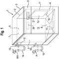
- FIG. 1 shows a schematic spatial representation of an embodiment of a dishwasher 1 according to the invention.
- This has a washing container 2, which is arranged in the interior of a housing 3 of the dishwasher 1.
- the washing compartment 2 comprises a first side wall 4, a second side wall 5, a rear wall 6, a top wall 7 and a floor pan 8.
- Its walls 4, 5, 6, 7 are preferably made of stainless steel sheet.
- the base pan 8 can preferably be a plastic part.
- the washing container 2 is used in particular to hold items to be washed while carrying out a washing cycle for cleaning and / or drying the same.
- it has a cuboid geometry with a loading opening arranged at the front.
- the loading opening provided on the front of the washing compartment 2 can be closed by a door 9, so that an interior 10 of the washing compartment 2, which is also called a washing compartment 10, is essentially closed when the door 9 is closed.
- a water container 11 is arranged on the first side wall 4 of the washing compartment 2, shown on the right, in such a way that it is in thermal contact with the Rinse tank 2 is standing.
- the water tank 11 could also be arranged on the second side wall 5, on the rear wall 6, on the ceiling wall 7 or on the bottom wall 8 and thermally connected to the washing tank.
- one side of the water container 11 lies flush against the washing container 2.
- a filling valve 12 is provided as the filling device, the outlet of which via a valve Figure 1 Not shown line is connected to the water tank 11.
- the inlet of the filling valve 12 is connected to an inlet connection 13 arranged on the housing 3.
- the inlet connection 13 itself is connected via a preferably flexible inlet hose 14 to a water tap WH of a building-side cold water supply WH. In this way, it is possible to fill the water container 11 with water from the cold water supply WH on the building side, which typically has a temperature in the range from 10 ° C. to 20 ° C.
- This temperature of this water is generally below the temperature of the rinsing container 2 while a drying cycle is being carried out, so that a condensation surface 15 on the inside of the rinsing container 2 can be cooled by filling the water container 11 with water from the cold water installation WH on the building side.
- the coolable condensation surface 15 lies opposite the contact surface of the water container 11 on the washing container 2.
- the cooling of the condensation surface 15 can be promoted by thermally conductive properties of the material of the washing container 2, which is why the formation of the condensation surface 15 on a section of the washing container 2 made of stainless steel sheet is expedient.
- a drain valve 16 is provided as an emptying device, which makes it possible to drain the water in the water tank 11 into the rinsing chamber 10, where it can collect in a pump pot 17 integrated in the floor pan 8.
- a pump pot 17 integrated in the floor pan 8.
- the circulating pump is used to apply wash liquid to the wash ware, which can be formed using water, for example from the water tank 11.
- the drain pump serves to pump out a flushing liquid that is no longer required, for example dirty.
- their output is connected to a drain connection 18 arranged on the housing 3, which in turn is connected via a preferably flexible sewage hose 19 to a sewage pipe A installed on the building side.
- the dishwasher 1 also has a sequence control device 20, in which at least one intended sequence, in particular a dishwasher program, is stored for a wash cycle.
- the sequence control device 20 is in the exemplary embodiment of FIG Figure 1 arranged inside the door 9 of the washing compartment 2. However, it could also be arranged at another location, such as, for example, the base assembly of the dishwasher 1.
- An operator interface 21 is also arranged in the area of the door 9, which enables an input unit for inputting operating commands and an output unit for outputting information. However, the operating interface 21 could also be arranged at a different location on the dishwasher 1.
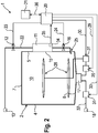
- FIG Figure 2 shows a more detailed representation of the functional components of the dishwasher 1 of FIG Figure 1 in schematic form.
- the filling valve 12 is connected via a connecting line 22 to the water tank 11 in such a way that it can be filled with water when the filling valve 12 is open.
- a return suction protection for example a pipe interruption, and / or a water treatment system, for example a softening and / or desalination system, can be provided in the connecting line 22.
- the filling valve 12 can be controlled by the sequence control device 20, for which purpose a control line 23 is provided, which is used to transmit control commands from the sequence control device 20 to the filling valve 12.
- Another control line 24 is used to transmit control commands from the sequence control device 20 to the drain valve 16 of the water container, so that the drain valve 16 can also be controlled by the flow control device 20.
- water located in the water tank 11 can be introduced into the washing chamber 10 in a controlled manner as required via the drain valve 16 and an outlet 25 adjoining it downstream.
- a circulation pump 26 An input side of a circulation pump 26 is connected to the pump pot 17 in a liquid-conducting manner.
- the circulating pump 26 enables flushing liquid from the pump bowl 17 via a heating device 27 and a spray device 28 arranged in the flushing chamber 10, in particular one or more rotating spray arms, into the Spray rinsing chamber 10 so as to treat items to be washed therein.
- the circulation pump 26 can be controlled, in particular controlled or regulated, with respect to its speed via a control line 29 by the sequence control device 20.
- the heating device 27 can also be adjusted, in particular controlled or regulated, by the sequence control device 20 via a further control line 30.
- a drain pump 31 is connected to the pump pot 17 in a liquid-conducting manner.
- the outlet side of the drain pump 31 is connected via a connecting line 32 to the drain connection 18 fixed to the housing, so that flushing liquid which is no longer required can be pumped out.
- the drain pump 31 can be controlled, in particular controlled or regulated, by the sequence control device 20 via a control line 33.
- the dishwasher 1 can comprise a sensor 34 which is designed to detect a parameter influencing a drying process of the wash ware.
- Figure 2 shows for example a sensor 34 which detects the temperature of the water in the water tank 11. This sensor 34 is connected via a signal line 35 to the sequence control device 20, which is designed to take into account the signals from the sensor 34 when controlling the fill level of the water container 11 at least during the drying cycle of a rinse cycle.
- the sequence control device 20 which is designed to take into account the signals from the sensor 34 when controlling the fill level of the water container 11 at least during the drying cycle of a rinse cycle.
- one or more sensors can be used to measure a temperature of the condensation surface 15, to measure an air temperature in the washing compartment 2, to measure an air humidity in the washing compartment 2, and / or to measure an amount, mass and / or a type of the the washware 2 can be provided.
- control lines 23, 24, 29, 30, 33 and the signal line 35 are used for unidirectional information transmission
- control and signal line 36 which the sequence control device 20 and the user interface 21 connects, preferably provided for bidirectional information transmission, which is also illustrated by corresponding arrows.
- operating commands can be transmitted from the operating interface 21 to the sequence control device 20 and operating information from the sequence control device 20 to the operating interface 21.
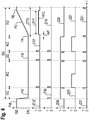
- Figure 3 shows an example of a sequence of a rinse cycle SG controlled by the sequence control device 20.
- the rinse cycle comprises a pre-rinse cycle VG, a cleaning cycle RG, an intermediate rinse cycle ZG, a rinse cycle KG and a drying cycle TG.
- a curve FS shows the fill level of the water tank 11 with water, a curve Z12 the operating state of the filling valve 12, a curve Z16 the operating state of the drain valve 16, a curve Z26 the operating state of the circulation pump 26, a curve Z27 the operating state of the Heating device 27 and a curve Z31 the operating state of the drain pump 31.
- the curve FS shows the fill level of the water tank 11 relative to a design-related maximum fill level FM in percent.
- the maximum fill level FM is reached when the entire volume of the water tank is filled with water.
- curves Z12 and Z16 taking the value “1” corresponds to an open valve and taking the value "0" to a closed valve.
- curves Z26, Z27 and Z31 the value "1" corresponds to an on state and the value "0" corresponds to an off state of the respective device.
- the water tank 11 is completely filled with water from a previous wash cycle, not shown, so that the curve FS assumes the value "100%".
- the water used to cool the condensation surface 15 during the previous wash cycle is introduced into the wash chamber 10 by briefly opening the drain valve 16 at the beginning of the first wash cycle partial wash cycle VG, in the example at the beginning of the pre-wash cycle VG, and circulated there as wash liquid by means of the circulation pump 26.
- the water stored in the storage container assumes room temperature, i.e. it has VG room temperature at the start of the pre-wash cycle, which is usually above the temperature of the building's cold water supply WH lies. For this reason A higher cleaning effect of the pre-rinse cycle VG can be achieved without having to switch on the heating device 27. If, however, a higher temperature is desired for the pre-rinse cycle VG, at least the heating energy required for the heating device then connected can be reduced. It is advantageous if the amount of water in the water tank corresponds exactly to the water requirement of the pre-rinse cycle VG. Alternatively, it would also be possible to use the water used to cool the condensation surface 15 during the previous rinse in a later partial rinse of the rinse.
- the circulation pump 26 is switched off and the drain pump 31 is switched on in order to pump off the now dirty washing liquid.
- the rinsing chamber is supplied with clean water from the cold water supply WH by simultaneously opening the filling valve 12 and the drain valve 16 of the water container 11.
- the circulation pump 26 and the heating device 27 are also switched on at the beginning of the cleaning cycle RG.
- the heating device 27 is switched off again.
- the temperature of the rinsing liquid can be measured with a sensor, not shown, e.g. on or in the rinsing container.
- the circulation pump 26 remains switched on for a so-called post-washing phase in order to continue cleaning the wash ware.
- the circulation pump 26 is also switched off and the drain pump 31 is switched on in order to pump out the now dirty rinsing liquid from the cleaning cycle RG.
- intermediate rinse cycle ZG is analogous to the cleaning cycle RG, although the heater 27 can generally not be switched on.
- the drain pump 31 is switched on in order to pump out as large an amount of the hot rinse aid liquid that drips from the wash ware early on from the dishwasher 1, so as to reduce the evaporation of rinse aid liquid and steam formation in the wash container, so that the drying effect can be increased.
- This switch-on state of the drain pump is in the Figure 3 plotted in the drain curve Z31 of the drain pump and labeled LPA.
- a short dripping phase AP may be provided at the beginning of the drying cycle TG, which serves to drain a substantial part of the rinse aid adhering to the items to be washed before the water container is filled with water the cold water supply takes place. If the filling of the water container with water is only started after this draining phase, the heating of the water in the water container 11 can be reduced over the entire time period ZTG of the drying cycle TG, which benefits the drying efficiency.
- the filling level FS of the water container 11 is gradually increased from an initial filling level FA to a final filling level FE.
- the initial fill level FA essentially corresponds to that of an empty water container.
- the final fill level FE is reached in the water tank 11 when it is essentially filled with water up to its maximum fill level or maximum level FM, ie the fill volume of the water tank is then essentially completely filled with water.
- the several filling phases FP1, FP2, FP3, viewed in accumulation extend over a substantial part of the duration ZTG of the drying cycle TG, whereby a substantial part is understood to mean at least 10%.
- the multiple filling phases occur in total extend over at least 20%, preferably over at least 40%, particularly preferably over at least 60%, and most preferably over at least 80%, of the duration ZTG of the drying cycle TG.
- the filling of the water container 11 starts at the beginning of the drying cycle TG after waiting for an initial dripping phase AP with the first partial filling phase FP1, by means of which the water level in the washing container 11 is partially filled from the level 0% to the level or partial filling level F1 with a partial filling quantity S1.
- This fill level F1 lies above the initial fill level FA of the water container 11 and here so far below the maximum fill level FE that two approximately equal partial fill quantities S2, S3, each corresponding approximately to the first partial fill quantity S1, can be filled until the maximum fill level FE is reached.
- This first filling phase FP1 is followed by two further partial filling phases FP2, FP3 at intervals or pauses P1, P2, during which the partial quantities S2, S3 are supplied to the water tank 11 step by step, ie in portions, by means of the filling valve 12.
- the overall filling process ends when the final filling level FE of the water container 11 is finally reached after the third filling of the partial filling quantity S3.
- the filling valve is designed as a shut-off valve which only has an open state and a closed state.
- the temporal extension i.e. the temporal distribution of the filling of the water container 11 brings about an evening of the cooling of the condensation surface 15, so that the desired condensation of water vapor can be achieved over a longer period of time without the cooling of the condensation surface 15 caused by the water container being filled with a too strong one Cooling of the wash chamber 10 and thus the wash ware would be effected, which would be detrimental to the evaporation of the wash liquid adhering to the wash ware, because the inherent heat stored in the wash ware during the previous rinse cycle would be removed too much and would no longer be sufficient for sufficient evaporation of the moisture on the wash ware. Overall, the drying efficiency can be improved.
- the time stretching of the filling of the water container is caused by dividing the filling process during the drying period ZTG into three partial filling phases FP1, FP2, FP3, during which the water container 11 has multiple stages with the partial filling quantities S1, S2, S3 at intervals or breaks P1, P2 is filled from each other.
- two intermediate levels F1, F2 are therefore provided between the initial level FA and the final level FE.
- the fill level After completion of the first fill level SU1, the fill level reaches a first intermediate fill level F1, after completion of the second stage SU2 a second intermediate fill level F2 and after completion of the third stage SU3 the final state FE. It goes without saying that only two filling stages or even further stages, in particular more than three filling stages, could be provided in further partial filling phases.
- the first stage SU1 serves to cool the condensation surface 15 in an early phase of the drying cycle TG in order to promote the condensation of water vapor.
- the first intermediate fill level F1 is only 40% of the maximum fill level FM in the exemplary embodiment, the rinsing chamber is cooled comparatively little.
- the second stage SU2 is used to compensate for a decrease in cooling which results from the heating of the water filled in the first stage SU1 as the drying cycle progresses.
- the third stage SU3 also serves to compensate for decreasing cooling.
- the temporal distribution of the stages SU1, SU2, SU3, the pauses or waiting times between these, during which no water is supplied to the water tank 11, and the partial filling quantities S1, S2, S3 of the stages SU1, SU2, SU3 can be predetermined or can be controlled using the signals from the sensor 34.
- the same partial filling phases or partial filling times, the same pause times it may also be expedient if one or more of these parameters are set variably or differently.
- the sequence control device 20 can in particular be carried out adaptively by the sequence control device 20, possibly with the aid of at least one sensor for determining one or more factors or parameters influencing the condensation effect.
- the residual amount of the rinsing liquid collected in the pump pot 17 is removed using the Pumped up drain pump 31, which can be composed, for example, of dripping water and condensed water.
- This draining phase is identified in the curve Z31 as the switch-on state and is referred to as LPE.
- Figure 4 shows a further course of a rinse cycle SG, the one compared to the rinse cycle SG Figure 3 modified drying cycle TG 'and does not belong to the invention.
- the modification compared to the time-discrete, successive partial filling of the exemplary embodiment of Figure 3 consists in that a single continuous filling phase FPC with a continuous or continuous filling of the water container 11 is provided during a filling time period ZFP over almost the entire time period ZTG of the drying cycle TG '. This starts after the drip-off phase AP and only ends shortly before the end of the drying process when the water tank has reached its maximum fill level FE.
- the water tank 11 is filled with a filling speed which is substantially lower than that of the partial filling phases FP1, FP2, FP3.
- This reduction or throttling of the filling speed is shown in the example of Figure 4 achieved in that the filling valve 12 is only partially opened, which is shown by the curve Z12 'for the filling valve 12 assuming a value during the filling phase FPC which lies between the value "1" and the value "0".
- the filling valve is expediently designed as a control valve whose through-flow cross section or, more generally, the throughflow rate is adjustable.
- the continuous filling of the water tank here in the exemplary embodiment is carried out by means of the filling valve in such a way that the filling level curve FC for the water level in the water tank between the starting filling level AC and the final filling level FE increases essentially continuously, in particular largely linearly.
- a suitable filling speed could, however, also be achieved by throttling the supplied water flow in another way, for example by reducing the cross-section of the connecting line 22, a bypass being provided for filling the rinsing container 11 with water directly absorbed by the cold water supply, for example during the cleaning cycle RG can, in order to be able to fill the washing container quickly.
- a dishwasher with a water container acting as a heat exchanger can be used in this way, in which by filling the heat exchanger according to the invention in several stages or alternatively and not part of the invention largely continuously over the entire drying period, preventing excessive cooling of the interior of the rinsing container and still producing a sufficiently cool condensation surface can be generated.
- the drying process can be controlled in particular as a function of temperature and / or load (in particular the load quantity, type of load), for example by using one or more sensors. In many cases, energy can be advantageously saved by lowering the rinse aid temperature with the same drying performance.
- the condensation performance of the condensation surface can be adapted to the respectively present one or more parameters during the drying cycle which influence the drying effect of the condensation surface.
- These parameters can include, for example, the inlet temperature of the incoming cold water, the size of the condensation surface, the temperature of the wash ware to be dried, the temperature in the wash tank, material properties of the water tank and / or wash tank and / or, feed lines, the amount of water on the wash ware after the preceding liquid-carrying wash cycle , the filling volume of the water container and / or the rinsing container, the temperature of the rinse cycle preceding the drying cycle, etc., etc.
- the water container is filled in portions, ie through successive successive, time-delayed partial filling cycles.
- several degrees of freedom are provided, with which an improved setting of the cooling capacity of the water container with regard to the condensation surface in thermal contact with it is specifically adapted to the prevailing circumstances, e.g. due to the respectively selected dishwasher program, the type of construction of the dishwasher, etc Vietnamese are given, is made possible.
- the cooling capacity of the water tank can therefore be flexibly adapted to different operating parameters.
Description
Die vorliegende Erfindung betrifft eine Geschirrspülmaschine, insbesondere Haushaltsgeschirrspülmaschine, mit einem Spülbehälter zur Aufnahme von Spülgut, mit wenigstens einem Wasserbehälter, der in wärmeleitendem Kontakt mit dem Spülbehälter zur Bereitstellung wenigstens einer Kondensationsfläche des Spülbehälters während wenigstens eines Trocknungsgangs wenigstens eines Spülgangs dient, und mit einer Befüllvorrichtung zum Befüllen des Wasserbehälters mit Wasser.The present invention relates to a dishwasher, in particular household dishwashing machine, with a washing container for holding items to be washed, with at least one water container which, in heat-conducting contact with the washing container, serves to provide at least one condensation surface of the washing container during at least one drying cycle, and with a filling device for filling the water tank with water.
Aus der Praxis ist eine Geschirrspülmaschine mit einem derartigen Wasserbehälter bekannt. Bei der bekannten Geschirrspülmaschine wird das Spülgut in einem dem Trocknungsgang bzw. Trocknungsvorgang zeitlich vorangehenden Klarspülgang mittels einer aufgeheizten Spülflüssigkeit beaufschlagt und dadurch erwärmt. Während des nachfolgenden Trocknungsgangs verdampft die am Spülgut anhaftende Spülflüssigkeit, so dass das Spülgut trocknet. Der dabei entstehende Wasserdampf kondensiert dann an den Innenseiten des Spülbehälters. Das Kondensieren des Wasserdampfs wird dabei durch eine Kondensationsfläche gefördert, welche durch im Wasserbehälter befindliches Wasser gekühlt wird.A dishwasher with such a water container is known in practice. In the known dishwasher, the items to be washed are subjected to a heated rinse liquid in a rinse cycle preceding the drying cycle or drying process and thus heated. During the subsequent drying cycle, the washing liquid adhering to the wash ware evaporates, so that the wash ware dries. The resulting water vapor then condenses on the inside of the rinsing container. The condensation of the water vapor is promoted by a condensation surface, which is cooled by water in the water tank.
Nachteilig bei der bekannten Geschirrspülmaschine ist jedoch, dass die Trocknungseffizienz den heutigen Ansprüchen nicht mehr gerecht wird.A disadvantage of the known dishwasher, however, is that the drying efficiency no longer meets today's requirements.
In der
Aufgabe der vorliegenden Erfindung ist es, eine Geschirrspülmaschine, insbesondere Haushaltsgeschirrspülmaschine, bereitzustellen, bei der die Trocknungseffizienz verbessert ist.The object of the present invention is to provide a dishwasher, in particular a domestic dishwasher, in which the drying efficiency is improved.
Die Aufgabe wird bei einer Geschirrspülmaschine der eingangs genannten Art dadurch gelöst, dass die Befüllvorrichtung derart ausgebildet ist, dass der Wasserbehälter verteilt über die Zeitdauer des jeweiligen Trocknungsgangs in mehreren Füllphasen mit Wasser befüllbar ist.The object is achieved in a dishwasher of the type mentioned at the outset in that the filling device is designed in such a way that the water tank can be filled with water in a number of filling phases over the period of the respective drying cycle.
Dadurch, dass die Wasserbefüllung des Wasserbehälters über die Zeitdauer des jeweiligen Trocknungsgangs hinweg verteilt erfolgen kann, d.h. der Wasserbehälter mit Teilmengen an Wasser während des jeweiligen Trocknungsgangs neu nachbefüllbar ist, kann eine ausreichende Kühlung der Kondensationsfläche des Spülbehälters über den gesamten Trocknungsvorgang hinweg betrachtet weitgehend sichergestellt werden. Denn der Wasserbehälter kann mit Wasser in mehreren Füllphasen nachbefüllt werden, das eine kältere Temperatur als das schon im Wasserbehälter befindliche, gespeicherte Wasser aufweist. Auf diese Weise kann die Kondensationswirkung des Wasserbehälters an eine Vielzahl von Betriebsparametern der erfindungsgemäßen Geschirrspülmaschine wie z.B. Temperatur des zulaufenden Wassers, Klarspültemperatur, Menge, Art, und/oder Wärmespeicherkapazität, insbesondere Masse des Spülguts, verwendete Materialien und/oder Wandstärken für Spülbehälter und/oder Wasserbehälter, Fassungsvolumen des Wasserbehälters und/oder des Spülbehälters, usw.... in einfacher und zuverlässiger Weise angepasst werden. Damit geht eine verbesserte Trocknungseffizienz einher.Due to the fact that the water tank can be filled over the period of the respective drying cycle, i.e. the water tank can be refilled with partial amounts of water during the respective drying cycle, sufficient cooling of the condensation surface of the rinsing tank can be largely ensured over the entire drying process . This is because the water tank can be refilled with water in several filling phases, which has a colder temperature than the water already stored in the water tank. In this way, the condensation effect of the water container on a variety of operating parameters of the dishwasher according to the invention such as the temperature of the incoming water, rinse temperature, amount, type, and / or heat storage capacity, in particular the mass of the wash ware, materials and / or wall thicknesses used for the rinse tank and / or water tank, volume of the water tank and / or the rinse tank, etc. can be customized in a simple and reliable manner. This goes hand in hand with improved drying efficiency.
Bei der erfindungsgemäßen Geschirrspülmaschine kann das Spülgut, insbesondere zu spülendes Geschirr, in einen Spülbehälter eingebracht und dort in einem Spülprozess, der auch Spülgang genannt wird, unter Zuhilfenahme von Spülflüssigkeit gereinigt und anschließend getrocknet werden. Der Spülbehälter kann dabei insbesondere aus Blechteilen und/oder aus Kunststoffteilen zusammengesetzt sein, wobei eine Beschickungsöffnung zum Einbringen und Entnehmen von Spülgut durch eine Tür verschließbar ist, so dass der Innenraum des Spülbehälters der auch Spülkammer genannt wird, bei geschlossener Tür im Wesentlichen abgeschlossen ist.In the dishwasher according to the invention, the items to be washed, in particular dishes to be washed, can be introduced into a washing container and cleaned there in a washing process, which is also called a washing cycle, with the aid of washing liquid and then dried. The washing compartment can in particular be composed of sheet metal parts and / or plastic parts, a loading opening for introducing and removing items to be washed being closable by a door, so that the interior of the washing compartment, which is also called the washing compartment, is essentially closed when the door is closed.
Dabei wird unter einer Spülflüssigkeit, auch Spülflotte genannt, eine Flüssigkeit verstanden, welche dazu vorgesehen ist, auf das Spülgut aufgebracht zu werden, um dieses zu reinigen und/oder in anderer Weise zu behandeln. Eine Spülflüssigkeit besteht in aller Regel zu einem überwiegenden Teil aus Wasser. Dabei kann die Spülflüssigkeit je nach Betriebsphase der Geschirrspülmaschine mit Reinigungsmitteln, mit Reinigungshilfsmitteln, wie beispielsweise Klarspülmittel und/oder mit Schmutz, der vom Spülgut gelöst wurde, angereichert sein.A rinsing liquid, also called a rinsing liquor, is understood to be a liquid which is intended to be applied to the items to be washed in order to clean and / or treat them in another way. A rinsing liquid usually consists mostly of water. Depending on the operating phase of the dishwasher, the washing liquid can be enriched with cleaning agents, with cleaning aids such as rinse aid and / or with dirt that has been detached from the items to be washed.
Ziel ist es dabei vorzugsweise, einen Spülgang zweckmäßigerweise so durchzuführen, dass ein vordefiniertes Reinigungsergebnis und ein vordefiniertes Trocknungsergebnis möglichst effizient erreicht werden. Gefordert ist dabei insbesondere eine hohe Gesamteffizienz, welche sich aus der Reinigungseffizienz und der Trocknungseffizienz ergibt. Die Reinigungseffizienz entspricht dabei insbesondere dem Verhältnis des mittels eines Spülgangs erzielten Reinigungsergebnisses und dem hierzu erforderlichen Aufwand, wobei der Aufwand mehrere Dimensionen, beispielsweise den Energiebedarf, den Wasserbedarf und/oder den Zeitbedarf, umfassen kann. Weiterhin entspricht die Trocknungseffizienz insbesondere dem Verhältnis des mittels eines Spülgangs erzielten Trocknungsergebnisses und dem hierzu erforderlichen Aufwand, wobei der Aufwand auch hier mehrere Dimensionen, beispielsweise den Energiebedarf und/oder den Zeitbedarf, umfassen kann.The aim is preferably to carry out a rinse cycle in such a way that a predefined cleaning result and a predefined drying result are achieved as efficiently as possible. In particular, a high overall efficiency is required, which results from the cleaning efficiency and the drying efficiency. The cleaning efficiency corresponds in particular to the ratio of the cleaning result achieved by means of a rinse cycle and the effort required for this, the effort being able to include several dimensions, for example the energy requirement, the water requirement and / or the time requirement. Furthermore, the drying efficiency corresponds in particular to the ratio of the drying result achieved by means of a rinse cycle and the effort required for this, the effort also can include several dimensions here, for example the energy requirement and / or the time requirement.
Bei der erfindungsgemäßen Geschirrspülmaschine ist zweckmäßigerweise eine Ablaufsteuereinrichtung vorgesehen, welche einen Spülgang nach einem vorgegebenen Ablauf automatisch steuert. Dabei können in der Ablaufsteuereinrichtung mehrere vorgegebene Abläufe für einen Spülgang hinterlegt sein, von denen jeweils einer zur Durchführung eines Spülgangs herangezogen wird. Die Auswahl eines bestimmten Ablaufs kann insbesondere durch einen Bediener durchgeführt werden. Hierzu kann beispielsweise eine mit der Ablaufsteuereinrichtung verbundene Bedienschnittstelle vorgesehen sein, welche eine Eingabeeinheit zur Eingabe von Bedienbefehlen umfasst. Die Bedienschnittstelle kann zudem eine Ausgabeeinheit zur Ausgabe von Informationen an den Bediener aufweisen. Ggf. ist auch eine voll automatische Auswahl eines Geschirrspülprogramms durch die Ablaufsteuereinrichtung möglich.In the dishwasher according to the invention, a sequence control device is expediently provided, which automatically controls a wash cycle according to a predetermined sequence. In this case, a plurality of predefined sequences for a rinse cycle can be stored in the sequence control device, one of which is used to carry out a rinse cycle. The selection of a specific sequence can be carried out in particular by an operator. For this purpose, for example, an operating interface connected to the sequence control device can be provided, which comprises an input unit for entering operating commands. The operator interface can also have an output unit for outputting information to the operator. Possibly. A fully automatic selection of a dishwashing program by the sequence control device is also possible.
Die Ablaufsteuereinrichtung ist so insbesondere ausgebildet, dass ein Spülgang durchführbar ist, der wenigstens einen Teilspülgang zur Reinigung des Spülguts unter Zuhilfenahme von Spülflüssigkeit und mindestens einen Teilspülgang zum Trocknen des Spülguts umfasst.The sequence control device is designed in particular in such a way that a rinse cycle can be carried out, which comprises at least one partial rinse cycle for cleaning the washware with the aid of rinsing liquid and at least one partial rinse cycle for drying the washware.
Ein vorgesehener Ablauf eines derartigen Spülgangs sieht zur Reinigung des Spülguts beispielhaft mehrere Teilspülgänge, nämlich in dieser zeitlichen Reihenfolge insbesondere einen Vorspülgang, einen Reinigungsgang, einen Zwischenspülgang und einen Klarspülgang, vor, bei denen das Spülgut jeweils mit einer Spülflüssigkeit beaufschlagt wird. Diese Teilspülgänge werden daher als spülflüssigkeitsführende Teilspülgänge bezeichnet. Weiterhin sieht der vorgesehene Ablauf einen sich an die spülflüssigkeitsführenden Teilspülgänge anschließenden, nachfolgenden Teilspülgang zum Trocknen des gereinigten Spülguts, nämlich einen Trocknungsgang bzw, Trocknungsvorgang, vor.An envisaged sequence of such a wash cycle provides, for example, a plurality of partial wash cycles for cleaning the wash ware, namely, in particular in this chronological order, a pre-wash cycle, a cleaning cycle, an intermediate rinse cycle and a rinse cycle, in each of which the wash ware is subjected to a washing liquid. These partial rinse cycles are therefore referred to as partial rinse cycles carrying rinsing liquid. Furthermore, the proposed sequence provides a subsequent partial rinse following the rinsing liquid-carrying partial rinses for drying the cleaned items, namely a drying cycle or drying process.
Es können jedoch auch Abläufe vorgesehen sein, bei denen einer oder mehrere dieser spülflüssigkeitsführenden Teilspülgänge ausgeblendet sind. Auch sind Abläufe des Spülgangs möglich, bei denen einer oder mehrere dieser Teilspülgänge mehrfach durchlaufen werden.However, processes can also be provided in which one or more of these partial rinse cycles carrying rinsing liquid are hidden. It is also possible to run the rinse cycle in which one or more of these partial rinse cycles are run through several times.
Der Vorspülgang dient im Beispiel vor allem der Entfernung von gröberen Verschmutzungen vom Spülgut. Der Zweck des nachfolgenden Reinigungsgangs besteht darin, Verschmutzungen vollständig von dem Spülgut zu entfernen, wozu eine mit Reinigungsmittel versetzte Spülflüssigkeit verwendet werden kann. Der nun durchgeführte Zwischenspülgang dient insbesondere der Entfernung von Reinigungsmittelresten, welche am Spülgut anhaften. Der darauffolgende Klarspülgang ist insbesondere zur Vermeidung von Flecken auf dem Spülgut, welche durch gelöste Stoffe im Wasser, wie beispielsweise Salz und/oder Kalk, entstehen könnten, vorgesehen. Hierzu kann die Spülflüssigkeit während des Klarspülgangs mit Klarspülmittel versetzt werden. Eine weitere Aufgabe des Klarspülgangs besteht darin, den nachfolgenden Trocknungsgang vorzubereiten. Dazu kann das Spülgut während des Klarspülgangs auf eine hohe Temperatur aufgeheizt werden.In the example, the pre-rinse cycle is used primarily to remove coarser soiling from the wash ware. The purpose of the subsequent cleaning cycle is to completely remove dirt from the items to be washed, for which purpose a washing liquid mixed with cleaning agent can be used. The intermediate rinse cycle now carried out serves in particular to remove residues of cleaning agent which adhere to the items to be washed. The subsequent rinse cycle is intended, in particular, to avoid stains on the wash ware, which could be caused by dissolved substances in the water, such as salt and / or lime. For this purpose, the rinsing liquid can be mixed with rinse aid during the rinse cycle. Another task of the final rinse cycle is to prepare the subsequent drying cycle. To do this, the dishes can be heated to a high temperature during the rinse cycle.
Der Trocknungsgang beginnt mit der Beendigung der Beaufschlagung des Spülguts mit der Spülflüssigkeit des letzten spülflüssigkeitsführenden Teilspülgangs, also in der Regel nach der Beaufschlagung des Spülguts mit der Klarspülflüssigkeit des Klarspülgangs. Ggf. kann er mit einer sogenannten Abtropfphase eingeleitet werden, während der Flüssigkeit noch vom Spülgut abtropft und am Boden des Spülbehälters gesammelt und vorzugsweise mit Hilfe einer Laugenpumpe aus dem Spülbehälter abgepumpt wird. Nach dem Ende des Klarspülgangs bzw. insbesondere nach Ende der etwaig vorgesehenen Abtropfphase verdunstet die am heißen Spülgut anhaftende Spülflüssigkeit und schlägt sich an der Innenseite des Spülbehälters aufgrund der dort herrschenden niedrigeren Temperatur ab. Das Ende des Trocknungsgangs bestimmt sich durch denjenigen durch das jeweilige Spülprogramm vorgegebenen Zeitpunkt, zu dem die Entnahme des Spülguts aus dem Spülbehälter im trockenen Zustand frühestmöglich vorgesehen ist. Dieser Zeitpunkt fällt in der Regel mit demjenigen Zeitpunkt zusammen, zu dem der Spülgang beendet wird. Die Beendigung des Trocknungsgangs und des Spülgangs insgesamt kann dem Bediener über die Bedienschnittstelle mitgeteilt werden.The drying cycle begins when the load on the wash ware is rinsed with the rinse liquid of the last partial rinse cycle carrying rinse liquid, that is to say generally after the wash rinse cycle has been loaded with the rinse liquid. Possibly. it can be initiated with a so-called draining phase, while the liquid is still dripping off the items to be washed and collected at the bottom of the washing container and is preferably pumped out of the washing container with the aid of a drain pump. After the end of the rinse cycle or in particular after the end of the drip phase, if any, the washing liquid adhering to the hot washware evaporates and is knocked off on the inside of the washing container due to the lower temperature prevailing there. The end of the drying cycle is determined by the point in time specified by the respective washing program at which the removal of the dishes from the washing container in the dry state is provided as early as possible. This time usually coincides with the time at which the rinse cycle ends. The end of the drying cycle and the rinsing cycle as a whole can be communicated to the operator via the user interface.
Die erfindungsgemäße Geschirrspülmaschine kann dabei durch die Ablaufsteuereinrichtung steuerbare Mittel aufweisen, welche die automatische Beaufschlagung von Spülgut mit Spülflüssigkeit während der spülflüssigkeitsführenden Teilspülgänge ermöglichen. Insbesondere können diese Mittel eine Umwälzpumpe und mindestens eine im Innern des Spülbehälters angeordnete Sprüheinrichtung, insbesondere einen oberen und einen unteren rotierbaren Sprüharm umfassen. Weiterhin kann die Geschirrspülmaschine eine durch die Ablaufsteuereinrichtung steuerbare, vorzugsweise elektrische, Heizeinrichtung aufweisen, um die Spülflüssigkeiten der einzelnen spülflüssigkeitsführenden Teilspülgänge auf die jeweils erforderliche Temperatur zu bringen. Um die zum Spülen vorgesehene Spülflüssigkeit mit den vorgesehenen Reinigungs- und/oder Zusatzstoffen versehen zu können, kann die Geschirrspülmaschine weiterhin eine durch die Ablaufsteuereinrichtung steuerbare Dosiereinrichtung aufweisen.The dishwasher according to the invention can have means which can be controlled by the sequence control device and which allow the automatic loading of washware with washing liquid during the partial washing cycles carrying the washing liquid. In particular, these means can be a circulation pump and comprise at least one spray device arranged in the interior of the washing container, in particular an upper and a lower rotatable spray arm. Furthermore, the dishwasher can have a preferably electrical heating device which can be controlled by the sequence control device in order to bring the washing liquids of the individual washing liquid-carrying partial wash cycles to the respectively required temperature. In order to be able to provide the washing liquid provided for washing with the provided cleaning agents and / or additives, the dishwasher can furthermore have a metering device which can be controlled by the sequence control device.
Die erfindungsgemäße Geschirrspülmaschine weist weiterhin wenigstens einen Wasserbehälter zur Aufnahme von Wasser auf, der in wärmeleitendem Kontakt mit dem Spülbehälter zur Bereitstellung wenigstens einer Kondensationsfläche steht. Der Wasserbehälter ist über eine Befüllvorrichtung mit Wasser befüllbar. Die Befüllvorrichtung kann insbesondere durch die Ablaufsteuereinrichtung der Geschirrspülmaschine steuerbar sein, die zur Steuerung mindestens eines Spülgangs zum Reinigen von Spülgut dient. Sie kann vorzugsweise als ein durch die Ablaufsteuereinrichtung steuerbares Füllventil gebildet sein. Dabei ist vorgesehen, den Wasserbehälter verteilt über die der Zeitdauer des Trocknungsgangs in mehreren Füllphasen mit Wasser zu befüllen, was durch eine entsprechende Steuerung der Befüllvorrichtung, insbesondere des Füllventils, erfolgen kann. Akkumuliert über alle Füllphasen zusammen betrachtet wird somit der Füllstand des Wasserbehälters während des Trocknungsgangs von einem Ausgangsfüllstand bis zu einem Endfüllstand immer mehr gesteigert. Über die Gesamtdauer des Trocknungsgangs hinweg verteilt wird also Wasser in den Wasserbehälter nachgefüllt, so dass dessen Wasserpegel ansteigt. Die Befüllung des Wasserbehälters beginnt damit insbesondere zu dem Zeitpunkt, an dem dessen Ausgangsfüllstand erstmalig erhöht wird, und endet vorzugsweise zu dem Zeitpunkt, an dem dessen Endfüllstand endgültig erreicht wird.The dishwasher according to the invention also has at least one water container for holding water, which is in heat-conducting contact with the washing container for providing at least one condensation surface. The water tank can be filled with water via a filling device. The filling device can in particular be controllable by the sequence control device of the dishwasher, which is used to control at least one wash cycle for cleaning items to be washed. It can preferably be designed as a filling valve that can be controlled by the sequence control device. It is provided to fill the water tank with water over a period of the drying cycle in several filling phases, which can be done by a corresponding control of the filling device, in particular the filling valve. Accumulated across all filling phases, the fill level of the water container during the drying cycle is increased from an initial fill level to a final fill level. Spread over the entire duration of the drying cycle, water is therefore refilled into the water tank, so that its water level rises. The filling of the water container thus begins, in particular, at the point in time at which its initial fill level is increased and preferably ends at the point in time at which its final fill level is finally reached.
Ziel ist es hierbei, wenigstens eine an einer Innenseite des Spülbehälters vorgesehene Kondensationsfläche wenigstens auf einem Teil ihrer Fläche zu kühlen. Hierzu kann der Wasserbehälter zweckmäßigerweise mit Kaltwasser, insbesondere aus einem Kaltwassernetz, befüllt werden, welches beispielsweise eine Temperatur von weniger als 30°C, weniger als 20°C oder weniger als 15°C aufweist. Ein derartiger Wasserbehälter wird auch Kaltwassertasche oder Wärmetauscher genannt.The aim here is to cool at least one condensation surface provided on an inside of the rinsing container on at least part of its surface. For this purpose, the water container can expediently be filled with cold water, in particular from a cold water network, which for example has a temperature of less than 30 ° C, less than 20 ° C or less than 15 ° C. Such a water tank is also called a cold water bag or heat exchanger.
Der jeweilige Wasserbehälter kann insbesondere flächig an einer Seitenwand oder an einer Rückwand des Spülbehälters anliegen. Die kühlbare Kondensationsfläche entspricht dabei jenem Bereich des Spülbehälters, der in thermischem Kontakt mit dem Spülbehälter steht.The respective water container can in particular lie flat against a side wall or against a rear wall of the rinsing container. The coolable condensation surface corresponds to that area of the washing compartment that is in thermal contact with the washing compartment.
Insbesondere ist vorgesehen, dass sich die mehreren Füllphasen über einen wesentlichen Teil der Dauer des Trocknungsgangs erstrecken. Hierunter kann vorzugsweise verstanden werden, dass sich die mehreren Füllphasen insgesamt, d.h. akkumuliert, über wenigstens 10% der Dauer des Trocknungsgangs erstrecken. Auf diese Weise kann eine Kühlung der Kondensationsfläche, welche das Auskondensieren von Wasserdampf an der Innenseite des Spülbehälters fördert, während des Trocknungsgangs über einen längeren Zeitraum als bei einem anfänglichen Komplettbefüllen des Wasserbehälters aufrecht erhalten werden, ohne dass dadurch der Innenraum des Spülbehälters und das darin befindliche Spülgut allzu stark abkühlt, was die Verdunstungsneigung von am Spülgut anhaftender Spülflüssigkeit senken würde.In particular, it is provided that the multiple filling phases extend over a substantial part of the duration of the drying cycle. This can preferably be understood to mean that the multiple filling phases as a whole, i.e. accumulated, extend over at least 10% of the duration of the drying cycle. In this way, cooling of the condensation surface, which promotes the condensation of water vapor on the inside of the rinsing container, can be maintained over a longer period of time during the drying cycle than with an initial complete filling of the water container, without the interior of the rinsing container and the inside of it Washware cools down too much, which would reduce the tendency of evaporation of washing liquid adhering to the washware.
Im Vergleich zu Lösungen, bei denen die Gesamt- bzw. Komplettbefüllung des Wasserbehälters bei oder kurz nach Beginn des Trocknungsgangs in möglichst kurzer Zeit durchgeführt wird, kann so die Trocknungseffizienz deutlich erhöht werden. Insbesondere kann eine dort in einer frühen Phase des Trocknungsgangs entstehende zu starke Abkühlung des Spülguts vermieden werden, so dass die während des Klarspülgangs gespeicherte Eigenwärme des Spülguts und damit die Verdunstung am Spülgut über einen längeren Zeitpunkt, insbesondere weitgehend über die Gesamtdauer des Trocknungsgangs, auf einem hohen Niveau erhalten bleibt. Der bei einer Gesamt-oder Komplettbefüllung des Wasserbehälters zu Beginn des Trocknungsgangs, auftretende Effekt, dass das Auskondensieren an der Kondensationsfläche zu früh, insbesondere in der zweiten Hälfte oder in einer späten Phase des Trocknungsgangs auf Grund eines Anstiegs der Wassertemperatur im Wasserbehälter stark nachlässt, kann jetzt beim erfindungsgemäßen, über die Trocknungszeitdauer verteilten Befüllen des Wasserbehälters vermieden werden, da die zeitliche Streckung des Füllvorgangs eine Vergleichmäßigung der Temperatur des eingefüllten Wassers bewirkt.In comparison to solutions in which the total or complete filling of the water tank is carried out in the shortest possible time at or shortly after the start of the drying cycle, the drying efficiency can be significantly increased. In particular, excessive cooling of the items to be washed, which occurs there in an early phase of the drying cycle, can be avoided, so that the heat of the items to be washed stored during the rinsing cycle and thus the evaporation of the items to be washed over a longer time, in particular largely over the entire duration of the drying cycle, on one high level is maintained. The effect that occurs when the water container is completely or completely filled at the beginning of the drying cycle, that the condensation on the condensation surface diminishes too early, particularly in the second half or in a late phase of the drying cycle, due to an increase in the water temperature in the water container can now be avoided when filling the water container according to the invention, which is distributed over the drying time period, since the temporal extension of the filling process brings about an equalization of the temperature of the filled water.
Die jeweilige Dauer der jeweiligen Füllphase, die Gesamtzeitdauer der ein oder mehreren Füllphasen, etwaige Totzeiten zwischen mehreren sukzessive aufeinaderfolgenden Füllphasen, und/oder ggf. auch der zeitliche Verlauf der Befüllung während der jeweiligen Füllphase kann unter Berücksichtigung der konstruktiven Gegebenheiten der Geschirrspülmaschine festgelegt werden. Berücksichtigt werden können beispielsweise der Maximalfüllstand des Spülbehälters, die Wärmedämmung des Innenraums des Spülbehälters gegenüber der Umgebung sowie die Wärmespeicherkapazität des Spülbehälters und seiner Tür. Berücksichtigt werden können aber auch sonstige Parameter des Spülgangs, beispielsweise die Ausgangstemperatur des Innenraums des Spülbehälters, die Temperatur des Wassers, mit dem der Wasserbehälter befüllt wird, sowie die Wärmespeicherkapazität des Spülguts.The respective duration of the respective filling phase, the total duration of the one or more filling phases, any dead times between several successive filling phases, and / or possibly also the time course of the filling during the respective filling phase can be determined taking into account the structural conditions of the dishwasher. For example, the maximum fill level of the washing container, the thermal insulation of the interior of the washing container with respect to the surroundings and the heat storage capacity of the washing container and its door can be taken into account. However, other parameters of the wash cycle can also be taken into account, for example the initial temperature of the interior of the wash tank, the temperature of the water with which the water tank is filled, and the heat storage capacity of the wash ware.
Insgesamt kann die Trocknungseffizienz eines Spülgangs mit der erfindungsgemäßen Geschirrspülmaschine deutlich verbessert werden. So ist eine Verkürzung der Dauer des Trocknungsgangs und damit des Spülgangs insgesamt bei gleichbleibendem Trocknungsergebnis möglich. Zudem kann eine Energieeinsparung erzielt werden, da die Verbesserung der Trocknungswirkung in vielen Fällen eine Senkung der Temperatur der Spülflüssigkeit während des vorangehenden spülflüssigkeitsführenden Teilspülgangs, insbesondere Klarspülgangs, erlaubt, ohne dass hierdurch Einbussen am Trocknungsergebnis und/oder eine Verlängerung des Trocknungsgangs im Vergleich zu herkömmlichen Geschirrspülmaschinen hinzunehmen wären. Auf diese Weise kann die Zeiteffizienz bzw. die Energieeffizienz der Geschirrspülmaschine insgesamt verbessert werden.Overall, the drying efficiency of a wash cycle can be significantly improved with the dishwasher according to the invention. This makes it possible to shorten the duration of the drying cycle and thus the rinse cycle overall with the drying result remaining the same. In addition, an energy saving can be achieved, since the improvement in the drying effect in many cases allows the temperature of the washing liquid to be reduced during the preceding washing liquid-carrying partial washing cycle, in particular rinse cycle, without thereby reducing the drying result and / or extending the drying cycle compared to conventional dishwashers would have to be accepted. In this way, the time efficiency or the energy efficiency of the dishwasher as a whole can be improved.
Gemäß einer vorteilhaften Weiterbildung der Erfindung erstrecken sich die mehreren Füllphasen insgesamt über wenigstens 20%, bevorzugt über wenigstens 40%, besonders bevorzugt über wenigstens 60%, und am meisten bevorzugt über wenigstens 80%, der Dauer des Trocknungsschritts. Je länger die von den mehreren, über die Gesamtzeitdauer des jeweiligen Trocknungsgangs verteilten Füllphasen belegte Zeitdauer im Vergleich zur Gesamtzeitdauer des gesamten Trocknungsgangs ist, desto mehr können die erfindungsgemäßen Vorteile realisiert werden. Insbesondere kann so die Verdunstung der Spülflüssigkeit und das Auskondensieren des dadurch entstehenden Wasserdampfs im Verlauf des Trocknungsgangs besonders gut vergleichmäßigt werden, was einer Optimierung der Trocknungseffizienz dienlich ist. Insbesondere kann es dazu zweckmäßig sei, wenn die ein oder mehreren Füllphasen die Gesamtzeitdauer des jeweiligen Trocknungsgangs möglichst gleichmäßig belegen.According to an advantageous development of the invention, the multiple filling phases extend over at least 20%, preferably over at least 40%, particularly preferably over at least 60%, and most preferably over at least 80%, of the duration of the drying step. The longer the time period occupied by the several filling phases distributed over the total time period of the respective drying cycle compared to the total time period of the entire drying cycle, the more the advantages according to the invention can be realized. In particular, the evaporation of the rinsing liquid and the condensation of the resulting water vapor in the course of the drying cycle can be evened out particularly well, which helps optimize drying efficiency. In particular, it can be expedient for this if the one or more filling phases occupy the total duration of the respective drying cycle as evenly as possible.
Nach einer zweckmäßigen Weiterbildung der Erfindung erstrecken sich die mehreren Füllphasen insgesamt über wenigstens 10 Minuten, bevorzugt über wenigstens 20 Minuten, besonders bevorzugt über wenigstens 30 Minuten, und am meisten bevorzugt über wenigstens 40 Minuten. Unabhängig von der vorgesehenen Dauer des Trocknungsgangs hat es sich gezeigt, dass die Trocknungseffizienz verbessert werden kann, wenn eine Mindestgesamtdauer für die mehreren Füllphasen festgelegt ist. Insbesondere in solchen Fällen, bei denen für den Trocknungsgang eine vergleichsweise kurze Gesamtdauer vorgesehen ist, kann so die Trocknungswirkung effizienter gestaltet werden.According to an expedient development of the invention, the multiple filling phases extend over a total of at least 10 minutes, preferably over at least 20 minutes, particularly preferably over at least 30 minutes, and most preferably over at least 40 minutes. Regardless of the intended duration of the drying cycle, it has been shown that the drying efficiency can be improved if a minimum total duration for the several filling phases is specified. In particular, in cases in which a comparatively short total duration is provided for the drying cycle, the drying effect can be made more efficient.
Gemäß einer vorteilhaften Weiterbildung der Erfindung beträgt der Ausgangsfüllstand des Wasserbehälters weniger als 10%, bevorzugt weniger als 5%, besonders bevorzugt weniger als 2%, eines konstruktiv bedingten Maximalfüllstands und/oder der Endfüllstand des Wasserbehälters mehr als 90%, bevorzugt mehr als 95%, besonders bevorzugt mehr als 98%, des konstruktiv bedingten Maximalfüllstands. Auf diese Weise kann die Trocknungseffizienz der Geschirrspülmaschine weiter verbessert werden. So ist es von Vorteil, wenn der Wasserbehälter zu Beginn des Trocknungsgangs einen möglichst geringen Füllstand aufweist. Auf diese Weise steht während des Trocknungsgangs nahezu das Maximalvolumen des Wasserbehälters zur Befüllung mit kaltem Wasser zur Verfügung, was die Steuerbarkeit der Kühlung der Kondensationsfläche verbessert. Wenn der Endfüllstand nahe am Maximalfüllstand liegt, kann die Kühlung der Kondensationsfläche auch gegen Ende des Trocknungsgangs effektiv aufrechterhalten werden.According to an advantageous development of the invention, the initial fill level of the water container is less than 10%, preferably less than 5%, particularly preferably less than 2%, of a design-related maximum fill level and / or the final fill level of the water container is more than 90%, preferably more than 95% , particularly preferably more than 98%, of the design-related maximum fill level. In this way, the drying efficiency of the dishwasher can be further improved. It is therefore advantageous if the water tank has the lowest possible fill level at the beginning of the drying cycle. In this way, almost the maximum volume of the water container for filling with cold water is available during the drying cycle, which improves the controllability of the cooling of the condensation surface. If the final fill level is close to the maximum fill level, the cooling of the condensation surface can also be effectively maintained towards the end of the drying cycle.
Gemäß der Erfindung erfolgt die Befüllung des Wasserbehälters in mehreren Stufen, d.h. die Befüllung des Wasserbehälters wird über die Zeitdauer des jeweiligen Trocknungsgangs betrachtet während mehrerer zeitlich aufeinanderfolgender Füllphasen schrittweise in mehreren Stufen durchgeführt. Eine derartige portionsweise Befüllung mittels der Befüllvorrichtung ermöglicht einerseits die Erzielung der erfindungsgemäßen Vorteile und ist andererseits einfach umzusetzen. Bei jeder Stufe der Befüllung wird die Befüllvorrichtung, insbesondere das Füllventil, zunächst geöffnet und dann wieder geschlossen, so dass sich der Füllstand bzw. Wasserpegel bei jeder Stufe erhöht. Falls die Befüllvorrichtung von der Steuereinrichtung der Geschirrspülmaschine aus kontrolliert bzw. gesteuert wird, sind dabei vergleichsweise wenige und einfache Steuerbefehle von der Ablaufsteuereinrichtung zu erzeugen und zur Befüllvorrichtung, insbesondere zum Füllventil zu übertragen. Die Füllphase beginnt dabei beim Öffnen des Steuerventils während der ersten Stufe und endet mit dem Schließen des Füllventils bei der letzten vorgesehenen Stufe. Die einzelnen Stufen können dabei identische oder unterschiedliche Füllstandszunahmen vorsehen. Der Abstand zwischen aufeinanderfolgenden Stufen kann gleichbleibend oder unterschiedlich sein.According to the invention, the filling of the water container takes place in several stages, ie the filling of the water container is considered over the time period of the respective drying cycle during several successive filling phases in several stages. Such filling in portions by means of the filling device enables the advantages according to the invention to be achieved on the one hand and is easy to implement on the other hand. At every stage of filling, the Filling device, in particular the filling valve, first opened and then closed again, so that the filling level or water level increases at each stage. If the filling device is controlled or controlled from the control device of the dishwasher, comparatively few and simple control commands are to be generated by the sequence control device and transmitted to the filling device, in particular to the filling valve. The filling phase begins with the opening of the control valve during the first stage and ends with the closing of the filling valve with the last intended stage. The individual stages can provide identical or different fill level increases. The distance between successive levels can be the same or different.
Gemäß einer vorteilhaften Weiterbildung der Erfindung erfolgt die Befüllung des Wasserbehälters portionsweise bzw. schrittweise vorzugsweise in wenigstens drei Stufen. Eine erste Stufe kann dabei eine hinreichende Kühlung der Kondensationsfläche insbesondere in einer anfänglichen Phase des Trocknungsgangs bewirken. Eine zweite Stufe kann dabei dazu dienen, dass eine Abnahme der Kühlung der Kondensationsfläche durch eine Erwärmung des während der ersten Stufe eingefüllten Wassers ausgeglichen wird. Diese zweite Befüllungsstufe kann insbesondere in einer mittleren Phase des Trocknungsgangs erfolgen. Eine dritte Stufe kann insbesondere unmittelbar vor Abschluss des Trocknungsgangs vorgesehen sein, wodurch ein Erreichen des Maximalfüllstands bewirkt werden kann, ohne dass der Spülbehälter während des Trocknungsgangs in unerwünschtem Umfang abgekühlt wird. Eine vollständige Füllung des Wasserbehälters zu Ende des Trocknungsgangs ist beispielsweise von Vorteil, wenn das im Wasserbehälter befindliche Wasser in einem später folgenden Spülgang zur Bildung einer Spülflüssigkeit verwendet werden soll. Die Wiederverwendung des Wassers des Wasserbehälters kann dabei in vielen Fällen den Energiebedarf der Geschirrspülmaschine senken, da es zu Beginn des folgenden Spülgangs Raumtemperatur aufweist, welche in der Regel höher liegt als die Temperatur einer üblichen gebäudeseitigen Kaltwasserversorgung. Diese Energieeinsparung kann maximiert werden, wenn der Wasserbehälter maximal befüllt wird.According to an advantageous development of the invention, the water container is filled in portions or in steps, preferably in at least three stages. A first stage can bring about sufficient cooling of the condensation surface, in particular in an initial phase of the drying cycle. A second stage can serve to compensate for a decrease in the cooling of the condensation surface by heating the water filled in during the first stage. This second filling stage can take place in particular in a middle phase of the drying cycle. A third stage can in particular be provided immediately before the drying cycle is completed, as a result of which the maximum fill level can be achieved without the washing container being cooled to an undesirable extent during the drying cycle. Completely filling the water container at the end of the drying cycle is advantageous, for example, if the water in the water container is to be used in a subsequent rinsing cycle to form a rinsing liquid. The reuse of the water in the water tank can in many cases lower the energy consumption of the dishwasher, since it has room temperature at the beginning of the following wash cycle, which is generally higher than the temperature of a conventional building-side cold water supply. This energy saving can be maximized if the water tank is filled to the maximum.
Nach einem nicht zur Erfindung gehörenden Alternative kann die Befüllung des Wasserbehälters über die Zeitdauer des jeweiligen Trocknungsgangs betrachtet während einer durchgehenden Füllphase kontinuierlich erfolgen. Unter einer kontinuierlichen Befüllung des Wasserbehälters wird verstanden, dass die Befüllvorrichtung, insbesondere das Füllventil, während des Trocknungsgangs lediglich einmal geöffnet und lediglich einmal geschlossen wird. Die erforderliche Dauer der Füllphase, welche sich aus dem zeitlichen Abstand zwischen dem Öffnen und dem Schließen des Füllventils ergibt, kann dabei dadurch erreicht werden, dass die Durchflussrate durch die Befüllvorrichtung, insbesondere das Füllventil, gering gehalten wird. Es wird also insbesondere eine gedrosselte Befüllung des Wasserbehälters mittels der Befüllvorrichtung während einer einzigen Füllphase vorgenommen, die sich im Wesentlichen mit der Gesamtzeitdauer des jeweiligen Trocknungsgangs deckt. Bei einer kontinuierlichen Befüllung kann das Kondensieren des Wasserdampfs besonders gleichmäßig erfolgen, was der Trocknungseffizienz besonders dienlich ist.According to an alternative which is not part of the invention, the filling of the water container can take place continuously over the duration of the respective drying cycle during a continuous filling phase. Under a continuous Filling the water container is understood to mean that the filling device, in particular the filling valve, is only opened once and closed only once during the drying cycle. The required duration of the filling phase, which results from the time interval between the opening and closing of the filling valve, can be achieved by keeping the flow rate through the filling device, in particular the filling valve, low. In particular, a throttled filling of the water container is carried out by means of the filling device during a single filling phase, which essentially coincides with the total duration of the respective drying cycle. In the case of continuous filling, the condensation of the water vapor can take place particularly uniformly, which is particularly beneficial for the drying efficiency.
Gemäß einer vorteilhaften Weiterbildung der Erfindung kann das Füllventil als Sperrventil ausgebildet sein. Unter einem Sperrventil wird ein solches Ventil verstanden, welches lediglich einen Offenzustand und einen Geschlossenzustand aufweist. Ein Sperrventil kann damit einfach aufgebaut und einfach zu steuern sein.According to an advantageous development of the invention, the filling valve can be designed as a check valve. A shut-off valve is understood to mean such a valve which only has an open state and a closed state. A check valve can thus be simply constructed and easy to control.
Nach einer zweckmäßigen Weiterbildung der Erfindung kann das Füllventil als Stellventil ausgebildet sein. Ein Stellventil ist so aufgebaut, dass die Durchflussrate des Wassers bei gegebenen Randbedingungen, beispielsweise bei gegebenem Druck des Wassers, steuerbar ist. Auf diese Weise kann der Füllstand optimal an die jeweiligen Erfordernisse angepasst werden.According to an expedient development of the invention, the filling valve can be designed as a control valve. A control valve is constructed in such a way that the flow rate of the water can be controlled under given boundary conditions, for example at a given pressure of the water. In this way, the fill level can be optimally adapted to the respective requirements.
Gemäß einer vorteilhaften Weiterbildung der Erfindung kann das Steuern der Fülleinrichtung unter Berücksichtigung von Signalen wenigstens eines Sensors erfolgen, der einen das Trocknen des Spülguts beeinflussenden Parameter erfasst. Im Vergleich zu einer vorgegebenen zeitlich orientierten Steuerung des Füllventils kann so die Trocknungseffizienz weiter verbessert werden. In Abhängigkeit vom realen Ablauf des Trocknungsvorgangs, der beispielsweise auch von Störgrößen, wie beispielsweise der Umgebungstemperatur, bestimmt wird, kann so eine weiter optimierte Befüllung des Wasserbehälters erreicht werden, was der Trocknungseffizienz zu Gute kommen kann.According to an advantageous development of the invention, the filling device can be controlled taking into account signals from at least one sensor which detects a parameter influencing the drying of the wash ware. The drying efficiency can thus be further improved in comparison with a predefined, time-oriented control of the filling valve. Depending on the real course of the drying process, which is also determined, for example, by disturbance variables such as the ambient temperature, a further optimized filling of the water tank can be achieved, which can benefit the drying efficiency.
Nach einer zweckmäßigen Weiterbildung der Erfindung kann ein Sensor zur Messung einer Temperatur des in dem Wasserbehälter befindlichen Wassers vorgesehen sein. Bei der Temperatur des im Wasserbehälter befindlichen Wassers handelt es sich um einen Parameter, der das Auskondensieren an der Kondensationsfläche wesentlich bestimmt. Die Erfassung dieser Temperatur und deren Berücksichtigung im Ablauf der Füllphase können daher zu einer wesentlichen Erhöhung der Trocknungseffizienz führen.According to an expedient development of the invention, a sensor for measuring a temperature of the water in the water container can be provided. At The temperature of the water in the water tank is a parameter that essentially determines the condensation on the condensation surface. The detection of this temperature and its consideration in the course of the filling phase can therefore lead to a significant increase in drying efficiency.
Gemäß einer vorteilhaften Weiterbildung der Erfindung kann ein Sensor zur Messung einer Temperatur der Kondensationsfläche vorgesehen sein. Auch bei der Temperatur der Kondensationsfläche handelt es sich um einen Parameter, der das Auskondensieren an der Kondensationsfläche bestimmt, so dass dessen Erfassung und Berücksichtigung eine Optimierung der Trocknungseffizienz ermöglicht.According to an advantageous development of the invention, a sensor for measuring a temperature of the condensation surface can be provided. The temperature of the condensation surface is also a parameter that determines the condensation on the condensation surface, so that its detection and consideration enables optimization of the drying efficiency.
Nach einer zweckmäßigen Weiterbildung der Erfindung kann ein Sensor zur Messung einer Lufttemperatur in dem Spülbehälter vorgesehen sein. Die Lufttemperatur in dem Spülbehälter beeinflusst sowohl die Verdunstung der Spülflüssigkeit am Spülgut als auch das Auskondensieren des entstehenden Wasserdampfs an der Kondensationsfläche. Damit kann auch dessen Erfassung und Berücksichtigung eine Optimierung der Trocknungseffizienz ermöglichen.According to an expedient development of the invention, a sensor for measuring an air temperature in the washing container can be provided. The air temperature in the washing compartment influences both the evaporation of the washing liquid on the items to be washed and the condensation of the water vapor formed on the condensation surface. This means that its detection and consideration can also enable drying efficiency to be optimized.
Gemäß einer vorteilhaften Weiterbildung der Erfindung kann ein Sensor zur Messung einer Luftfeuchtigkeit in dem Spülbehälter vorgesehen sein. Auch die Luftfeuchtigkeit in dem Spülbehälter beeinflusst die Verdunstung der Spülflüssigkeit am Spülgut und auch das Auskondensieren des entstehenden Wasserdampfs an der Kondensationsfläche, so dass deren Erfassung und Berücksichtigung eine weitere Optimierung der Trocknungseffizienz leisten kann.According to an advantageous development of the invention, a sensor for measuring an air humidity in the washing container can be provided. The air humidity in the washing compartment also influences the evaporation of the washing liquid on the items to be washed and also the condensation of the water vapor formed on the condensation surface, so that their detection and consideration can further optimize the drying efficiency.
Nach einer zweckmäßigen Weiterbildung der Erfindung kann ein Sensor zur Messung einer Menge, Masse und/oder einer Art des in dem Spülbehälter befindlichen Spülguts vorgesehen sein. Menge, Masse und/oder einer Art des in dem Spülbehälter befindlichen Spülguts beeinflussen den zeitlichen Verlauf der Abkühlung des Innenraums des Spülbehälters während des Trocknungsgangs wesentlich. Die Erfassung dieser Parameter und deren Berücksichtigung im Ablauf der Füllphase können daher zu einer wesentlichen Erhöhung der Trocknungseffizienz führen.According to an expedient development of the invention, a sensor can be provided for measuring a quantity, mass and / or a type of the wash ware located in the wash container. The amount, mass and / or type of washware in the wash container significantly influence the time course of the cooling of the interior of the wash container during the drying cycle. Recording these parameters and taking them into account during the filling phase can therefore lead to a significant increase in drying efficiency.
Gemäß einer vorteilhaften Weiterbildung der Erfindung kann zwischen dem Beginn des Trocknungsgangs und dem Beginn der ersten Füllphase insbesondere eine Abtropfphase vorgesehen sein. Auf diese Weise kann eine unerwünschte Erwärmung des Wassers im Wasserbehälter in einer anfänglichen Phase der Füllphase verringert werden, was die Trocknungseffizienz fördert.According to an advantageous development of the invention, in particular a dripping phase can be provided between the beginning of the drying cycle and the beginning of the first filling phase. In this way, undesirable heating of the water in the water tank in an initial phase of the filling phase can be reduced, which promotes drying efficiency.
Nach einer zweckmäßigen Weiterbildung der Erfindung kann die Befüllvorrichtung, insbesondere das Füllventil, zur Beschickung des Wasserbehälters mit Wasser aus einer externen Wasserversorgung vorgesehen sein. Bei der externen Wasserversorgung kann es sich beispielsweise um eine gebäudeseitige Kaltwasserversorgung handeln, welche typischerweise hinreichend kaltes Wasser bereitstellt.According to an expedient development of the invention, the filling device, in particular the filling valve, can be provided for charging the water container with water from an external water supply. The external water supply can be, for example, a cold water supply on the building side, which typically provides sufficiently cold water.
Die in den abhängigen Ansprüchen wiedergegebenen und/oder vorstehend erläuterten vorteilhaften Aus- und Weiterbildungen der Erfindung können einzeln oder in beliebiger Kombination miteinander bei der erfindungsgemäßen Geschirrspülmaschine vorgesehen sein.The advantageous refinements and developments of the invention reproduced in the dependent claims and / or explained above can be provided individually or in any combination with one another in the dishwasher according to the invention.
Weiterhin betrifft die Erfindung ein Verfahren zur Durchführung wenigstens eines Spülgangs zum Reinigen von Spülgut im Spülbehälter einer Geschirrspülmaschine, welche wenigstens einen Wasserbehälter, der in wärmeleitendem Kontakt mit dem Spülbehälter zur Bereitstellung wenigstens einer Kondensationsfläche des Spülbehälters während wenigstens eines Trocknungsgangs des jeweiligen Spülgangs dient, und eine Befüllvorrichtung zum Befüllen des Wasserbehälters mit Wasser umfasst, welches dadurch gekennzeichnet ist, dass der Wasserbehälter mittels der Befüllvorrichtung verteilt über die Zeitdauer des jeweiligen Trocknungsgangs in mehreren Füllphasen mit Wasser befüllt wird, wobei die Geschirrspülmaschine nach mindestens einem der vorhergehenden Aspekte ausgebildet ist. Gemäß der Erfindung wird der Wasserbehälter mittels der Befüllvorrichtung verteilt über die Zeitdauer des jeweiligen Trocknungsgangs in mehreren Füllphasen mit Wasser so befüllt wird, dass die Befüllung des Wasserbehälters über die Zeitdauer des jeweiligen Trocknungsgangs betrachtet während mehrerer zeitlich aufeinanderfolgender Füllphasen schrittweise in mehreren Stufen erfolgt und akkumuliert über alle Füllphasen zusammen betrachtet der Füllstand des Wasserbehälters während des Trocknungsgangs von einem Ausgangsfüllstand bis zu einem Endfüllstand immer mehr gesteigert wird.Furthermore, the invention relates to a method for carrying out at least one wash cycle for cleaning items to be washed in the wash tank of a dishwasher, which has at least one water tank which, in heat-conducting contact with the wash tank, provides at least one condensation surface of the wash tank during at least one drying cycle of the respective wash cycle, and one Filling device for filling the water container with water, which is characterized in that the water container is filled with water in several filling phases over the period of the respective drying cycle by means of the filling device, the dishwasher being designed according to at least one of the preceding aspects. According to the invention, the water container is filled with water in several filling phases over the period of the respective drying cycle in such a way that the filling of the water container over the period of the respective drying cycle is carried out step by step in several stages during several successive filling phases and accumulated over All filling phases taken together, the fill level of the water container is increased more and more during the drying cycle from an initial fill level to a final fill level.
Bei dem erfindungsgemäßen Verfahren ist insbesondere vorgesehen, dass die Füllphasen derart durchgeführt werden, dass sie sich über einen wesentlichen Teil der Dauer des Trocknungsgangs erstrecken.In the method according to the invention it is particularly provided that the filling phases are carried out in such a way that they extend over a substantial part of the duration of the drying cycle.
Das erfindungsgemäße Verfahren ermöglicht eine Verbesserung der Trocknungswirkung während des Trocknungsgangs einer mit einem Wasserbehälter der genannten Art ausgerüsteten Geschirrspülmaschine. Hierdurch ist eine Verkürzung der Dauer des Trocknungsgangs und damit des Spülgangs insgesamt bei gleichbleibendem Trocknungsergebnis möglich. Zudem kann eine Energieeinsparung erzielt werden, da die Verbesserung der Trocknungswirkung in vielen Fällen eine Senkung der Temperatur der Spülflüssigkeit während des vorangehenden spülflüssigkeitsführenden Teilspülgangs erlaubt, ohne dass hierdurch Einbußen am Trocknungsergebnis und/oder eine Verlängerung des Trocknungsgangs im Vergleich zu herkömmlichen Verfahren hinzunehmen wären. Auf diese Weise kann die Zeiteffizienz bzw. die Energieeffizienz beim Trocknen von Spülgut verbessert werden. Zudem kann das Verfahren bei konstruktiv einfach gehaltenen Geschirrspülmaschinen angewendet werden, da beispielsweise aufwendige Umluft- oder Abluftgebläse zur Trocknung des Spülguts in der Regel nicht erforderlich sind.The method according to the invention enables an improvement in the drying effect during the drying cycle of a dishwasher equipped with a water container of the type mentioned. This makes it possible to shorten the duration of the drying cycle and thus the rinsing cycle overall with the drying result remaining the same. In addition, an energy saving can be achieved, since the improvement in the drying effect in many cases allows the temperature of the washing liquid to be reduced during the preceding washing liquid-carrying part wash cycle, without sacrificing the drying result and / or extending the drying cycle compared to conventional processes. In this way, the time efficiency or the energy efficiency when drying wash ware can be improved. In addition, the method can be used in dishwashers with a simple design, since, for example, complex circulating air or exhaust air blowers are generally not required for drying the dishes.
Vorteilhafte Aus- und Weiterbildungen des erfindungsgemäßen Verfahrens sind bei der Beschreibung der erfindungsgemäßen Geschirrspülmaschine erläutert. Die Aus- und Weiterbildungen des erfindungsgemäßen Verfahrens können einzeln oder in beliebiger Kombination miteinander bei dem erfindungsgemäßen Verfahren zur Anwendung kommen.Advantageous developments and further developments of the method according to the invention are explained in the description of the dishwasher according to the invention. The training and further developments of the method according to the invention can be used individually or in any combination with one another in the method according to the invention.
Die Erfindung und ihre Weiterbildungen sowie deren Vorteile werden nachfolgend anhand von Figuren näher erläutert.The invention and its developments and their advantages are explained in more detail below with reference to figures.
Es zeigen:
-
Figur 1 - ein vorteilhaftes Ausführungsbeispiel einer zur erfindungsgemäßen Durchführung wenigstens eines Spülgangs erfindungsgemäß ausgebildeten Haushaltsgeschirrspülmaschine in einer schematischen räumlichen Ansicht,
-
Figur 2 - eine weitere Darstellung der
Geschirrspülmaschine von Figur 1 in einer schematischen Frontansicht, - Figur 3
- einen schematisierten, beispielhaften, zeitlichen Ablauf eines Spülgangs der erfindungsgemäßen Geschirrspülmaschine der
Figuren 2 , und - Figur 4
- einen nicht zur Erfindung gehörenden, schematisierten, beispielhaften, zeitlichen Ablauf eines Spülgangs derGeschirrspülmaschine der
Figuren 2 .
- Figure 1
- 1 shows an advantageous exemplary embodiment of a domestic dishwashing machine designed according to the invention for carrying out at least one wash cycle according to the invention, in a schematic spatial view,
- Figure 2
- another illustration of the dishwasher of
Figure 1 in a schematic front view, - Figure 3
- a schematic, exemplary, temporal sequence of a wash cycle of the dishwasher of the invention
Figures 1 ,2nd , and - Figure 4
- a schematic, exemplary, temporal sequence of a washing cycle of the dishwasher of the
Figures 1 ,2nd .
In den folgenden Figuren sind einander entsprechende Teile mit denselben Bezugszeichen versehen. Dabei sind nur diejenigen Bestandteile einer Geschirrspülmaschine mit Bezugszeichen versehen und erläutert, welche für das Verständnis der Erfindung erforderlich sind. Es versteht sich von selbst, dass die erfindungsgemäße Geschirrspülmaschine weitere Teile und Baugruppen umfassen kann.In the following figures, parts that correspond to one another are provided with the same reference symbols. Only those components of a dishwasher that are necessary for an understanding of the invention are provided and explained with reference numerals. It goes without saying that the dishwasher according to the invention can comprise further parts and assemblies.
Der Spülbehälter 2 dient insbesondere der Aufnahme von Spülgut während der Durchführung eines Spülgangs zum Reinigen und/oder Trocknen desselben. Er weist insbesondere eine quaderförmige Geometrieform mit einer frontal angeordneten Beschickungsöffnung auf. Die an der Vorderseite des Spülbehälters 2 vorgesehene Beschickungsöffnung ist durch eine Tür 9 verschließbar, so dass ein Innenraum 10 des Spülbehälters 2, der auch Spülkammer 10 genannt wird, bei geschlossener Tür 9 im Wesentlichen abgeschlossen ist.The
An der ersten, rechts dargestellten Seitenwand 4 des Spülbehälters 2 ist ein Wasserbehälter 11 derart angeordnet, dass dieser in thermischem Kontakt mit dem Spülbehälter 2 steht. Der Wasserbehälter 11 könnte jedoch auch an der zweiten Seitenwand 5, an der Rückwand 6, an der Deckenwand 7 oder an der Bodenwand 8 angeordnet und thermisch mit dem Spülbehälter verbunden sein. Im Beispiel der
Zum Befüllen des Wasserbehälters 11 mit Wasser ist als Befüllungsvorrichtung ein Füllventil 12 vorgesehen, dessen Ausgang über eine in
Weiterhin ist ein Ablassventil 16 als Entleerungsvorrichtung vorgesehen, welches es ermöglicht, das im Wasserbehälter 11 befindliche Wasser in die Spülkammer 10 abzulassen, wo es sich in einem in die Bodenwanne 8 integrierten Pumpentopf 17 sammeln kann. Im oder am Pumpentopf 17 ist eine in
Die Geschirrspülmaschine 1 weist ferner eine Ablaufsteuereinrichtung 20 auf, in der wenigstens ein vorgesehener Ablauf, insbesondere Geschirrspülprogramm, für einen Spülgang gespeichert ist. Die Ablaufsteuereinrichtung 20 ist im Ausführungsbeispiel der
Das Füllventil 12 ist dabei durch die Ablaufsteuereinrichtung 20 steuerbar, wozu eine Steuerleitung 23 vorgesehen ist, welche der Übertragung von Steuerbefehlen von der Ablaufsteuereinrichtung 20 zum Füllventil 12 dient. Eine weitere Steuerleitung 24 dient der Übertragung von Steuerbefehlen von der Ablaufsteuereinrichtung 20 zum Ablassventil 16 des Wasserbehälters, so dass auch das Ablassventil 16 durch die Ablaufsteuereinrichtung 20 steuerbar ist. Auf diese Weise kann im Wasserbehälter 11 befindliches Wasser über das Ablassventil 16 und einen sich daran stromabwärts anschließenden Ablauf 25 bedarfsgerecht gesteuert in die Spülkammer 10 eingeleitet werden.The filling
Eine Eingangsseite einer Umwälzpumpe 26 ist mit dem Pumpentopf 17 flüssigkeitsleitend verbunden. Die Umwälzpumpe 26 ermöglicht es, Spülflüssigkeit aus dem Pumpentopf 17 über eine Heizeinrichtung 27 und eine in der Spülkammer 10 angeordnete Sprüheinrichtung 28, insbesondere einen oder mehrere rotierende Sprüharme, in die Spülkammer 10 einzusprühen, um so darin befindliches Spülgut zu behandeln. Die Umwälzpumpe 26 ist dabei hinsichtlich ihrer Drehzahl über eine Steuerleitung 29 durch die Ablaufsteuereinrichtung 20 kontrollierbar, insbesondere steuerbar oder regelbar. Weiterhin ist die Heizeinrichtung 27 über eine weitere Steuerleitung 30 ebenfalls durch die Ablaufsteuereinrichtung 20 einstellbar, insbesondere steuerbar oder regelbar.An input side of a
Ferner ist eine Eingangsseite einer Laugenpumpe 31 mit dem Pumpentopf 17 flüssigkeitsleitend verbunden. Die Ausgangsseite der Laugenpumpe 31 ist dabei über eine Verbindungsleitung 32 mit dem gehäusefesten Ablaufanschluss 18 verbunden, so dass nicht mehr benötigte Spülflüssigkeit abgepumpt werden kann. Die Laugenpumpe 31 ist dabei über eine Steuerleitung 33 durch die Ablaufsteuereinrichtung 20 kontrollierbar, insbesondere steuerbar oder regelbar.Furthermore, an input side of a
Die erfindungsgemäße Geschirrspülmaschine 1 kann einen Sensor 34 umfassen, der zur Erfassung eines einen Trocknungsvorgang des Spülguts beeinflussenden Parameters ausgebildet ist.
Während es in aller Regel ausreichend ist, dass die Steuerleitungen 23, 24, 29, 30, 33 und die Signalleitung 35, wie durch entsprechende Pfeile veranschaulicht, zur unidirektionalen Informationsübertragung verwendet werden, ist eine Steuer- und Signalleitung 36, welche die Ablaufsteuereinrichtung 20 und die Bedienschnittstelle 21 verbindet, vorzugsweise zur bidirektionalen Informationsübertragung vorgesehen, was ebenfalls durch entsprechende Pfeile veranschaulicht ist. So können Bedienbefehle von der Bedienschnittstelle 21 zur Ablaufsteuereinrichtung 20 und Bedieninformationen von der Ablaufsteuereinrichtung 20 zur Bedienschnittstelle 21 übertragen werden.While it is generally sufficient that the
Die Kurve FS zeigt dabei den Füllstand des Wasserbehälters 11 relativ zu einem konstruktiv bedingten Maximalfüllstand FM in Prozent. Der Maximalfüllstand FM ist dann erreicht, wenn das gesamte Fassungsvolumen des Wasserbehälters mit Wasser gefüllt ist. Bei den Kurven Z12 und Z16 entspricht die Einnahme des Wertes "1" einem geöffneten Ventil und die Einnahme des Wertes "0" einem geschossenen Ventil. Weiterhin entspricht bei den Kurven Z26, Z27 und Z31 der Wert "1" einem Einschaltzustand und der Wert "0" einem Ausschaltzustand der jeweiligen Einrichtung.The curve FS shows the fill level of the
Zu Beginn des Spülgangs SG ist der Wasserbehälter 11 mit Wasser aus einem vorangegangenen nicht dargestellten Spülgang vollständig gefüllt, so dass die Kurve FS den Wert "100%" einnimmt. Das während des vorangegangenen Spülgangs zur Kühlung der Kondensationsfläche 15 verwendete Wasser wird zu Beginn des ersten spülflüssigkeitsführenden Teilspülgangs VG, im Beispiel zu Beginn des Vorspülgangs VG, durch kurzzeitiges Öffnen des Ablassventils 16 in die Spülkammer 10 eingeleitet und dort als Spülflüssigkeit mittels der Umwälzpumpe 26 umgewälzt. Durch eine derartige Verwendung des vormals zur Kühlung der Kondensationsfläche 15 verwendeten Wassers kann der Wasserbedarf der Geschirrspülmaschine verringert werden.At the beginning of the wash cycle SG, the
Wenn genügend viel Zeit zwischen dem Ende des Spülgangs eines gewählten Geschirrspülprogramms und einem neu gestarteten Geschirrspülprogramm vergangen ist, so nimmt das im Vorratsbehälter gespeicherte Wasser Raumtemperatur an, d.h. es weist zu Beginn des Vorspülgangs VG Raumtemperatur auf, welche üblicherweise über der Temperatur der gebäudeseitigen Kaltwasserversorgung WH liegt. Aus diesem Grund kann eine höhere Reinigungswirkung des Vorspülgangs VG erreicht werden, ohne dass hierzu die Heizeinrichtung 27 eingeschaltet werden müsste. Falls für den Vorspülgang VG jedoch eine höhere Temperatur gewünscht ist, kann so zumindest der hierzu erforderliche Heizenergieaufwand der dann hinzugeschalteten Heizungseinrichtung verringert werden. Dabei ist es von Vorteil, wenn die im Wasserbehälter befindliche Wassermenge gerade dem Wasserbedarf des Vorspülgangs VG entspricht. Alternativ wäre es auch möglich, das während des vorangegangenen Spülgangs zur Kühlung der Kondensationsfläche 15 verwendete Wasser in einem späteren Teilspülgang des Spülgangs zu verwenden.If a sufficient amount of time has passed between the end of the wash cycle of a selected dishwashing program and a newly started dishwashing program, the water stored in the storage container assumes room temperature, i.e. it has VG room temperature at the start of the pre-wash cycle, which is usually above the temperature of the building's cold water supply WH lies. For this reason A higher cleaning effect of the pre-rinse cycle VG can be achieved without having to switch on the
In einer Endphase des Vorspülgangs VG wird die Umwälzpumpe 26 abgeschaltet und die Laugenpumpe 31 eingeschaltet, um die nun verschmutzte Spülflüssigkeit abzupumpen.In a final phase of the pre-rinse cycle VG, the
Zu Beginn des nun folgenden Reinigungsgangs RG wird die Spülkammer mit sauberem Wasser von der Kaltwasserversorgung WH beschickt, indem gleichzeitig das Füllventil 12 und das Ablassventil 16 des Wasserbehälters 11 geöffnet wird. Ebenfalls zu Beginn des Reinigungsgangs RG werden die Umwälzpumpe 26 und die Heizeinrichtung 27 eingeschaltet. Wenn die gewünschte Temperatur der Spülflüssigkeit des Reinigungsgangs RG, beispielsweise im Bereich von 40°C bis 60°C erreicht ist, wird die Heizeinrichtung 27 wieder abgeschaltet. Die Temperatur der Spülflüssigkeit kann dabei mit einem nicht dargestellten Sensor z.B. am oder im Spülbehälter erfasst werden. Die Umwälzpumpe 26 bleibt dabei für eine sogenannte Nachwaschphase weiter eingeschaltet, um die Reinigung des Spülguts weiterzuführen. In einer Endphase des Reinigungsgangs RG wird auch die Umwälzpumpe 26 abgeschaltet und die Laugenpumpe 31 eingeschaltet, um die nun verschmutzte Spülflüssigkeit des Reinigungsgangs RG abzupumpen.At the beginning of the now following cleaning cycle RG, the rinsing chamber is supplied with clean water from the cold water supply WH by simultaneously opening the filling
Der nun folgende Zwischenspülgang ZG verläuft analog zum Reinigungsgang RG, wobei allerdings eine Zuschaltung der Heizeinrichtung 27 in der Regel unterbleiben kann.The now following intermediate rinse cycle ZG is analogous to the cleaning cycle RG, although the
Bei dem nun nachfolgenden Klarspülgang KG wird in einer anfänglichen Phase erneut Wasser von der Kaltwasserversorgung WH in die Spülkammer 10 eingeleitet, wozu das Füllventil 12 und das Ablassventil 16 des Wasserbehälters 11 erneut gleichzeitig geöffnet werden. Die nun gebildete Spülflüssigkeit wird nun mit der Umwälzpumpe 26 umgewälzt und dabei mit der Heizeinrichtung 27 auf eine vergleichsweise hohe Temperatur von beispielsweise zwischen 60°C und 80°C gebracht. Hierdurch wird auch das Spülgut stark erwärmt. Wenn die gewünschte Temperatur erreicht ist, was ebenfalls mit dem bereits erwähnten Sensor festgestellt werden kann, werden Umwälzpumpe 26 und Heizeinrichtung 27 abgeschaltet und der Klarspülgang KG damit beendet.In the subsequent rinse cycle KG, water is again introduced in an initial phase from the cold water supply WH into the rinsing
Mit dem Abschalten der Umwälzpumpe 26 beginnt die Trocknung des Spülguts und damit der Trocknungsgang TG. Dabei wird in dieser frühen Phase des Trocknungsgangs TG die Laugenpumpe 31 eingeschaltet, um eine möglichst große Menge der heißen, vom Spülgut abtropfenden Klarspülflüssigkeit frühzeitig aus der Geschirrspülmaschine 1 abzupumpen, um so die Verdunstung von Klarspülflüssigkeit und Dampfbildung im Spülbehälter zu verringern, so dass die Trocknungswirkung erhöht werden kann. Dieser Einschaltzustand der Laugenpumpe ist in der
Während der Zeitdauer ZTG des Trocknungsgangs TG sind nach Abschluss der Abtropfphase AP mehrere, hier drei, Füllphasen FP1, FP2, FP3 vorgesehen, in der der Füllstand FS des Wasserbehälters 11 von einem Ausgangsfüllstand FA bis zu einem Endfüllstand FE stufenweise erhöht wird. Der Ausgangsfüllstand FA entspricht hier im Ausführungsbeispiel im Wesentlichen dem eines leeren Wasserbehälters. Der Endfüllstand FE ist im Wasserbehälter 11 dann erreicht, wenn er im Wesentlichen bis auf seinen Maximalfüllstand bzw. Maximalpegel FM mit Wasser befüllt ist, d.h. das Füllvolumen des Wasserbehälters ist dann im Wesentlichen vollständig mit Wasser angefüllt. Erfindungsgemäß ist dabei vorgesehen, dass sich die mehreren Füllphasen FP1, FP2, FP3 akkumuliert betrachtet über einen wesentlichen Teil der Dauer ZTG des Trocknungsgangs TG erstrecken, wobei unter einem wesentlichen Teil wenigstens 10% verstanden wird. Vorteilhaft ist jedoch, wenn sich die mehreren Füllphasen insgesamt über wenigstens 20%, bevorzugt über wenigstens 40%, besonders bevorzugt über wenigstens 60%, und am meisten bevorzugt über wenigstens 80%, der Dauer ZTG des Trocknungsgangs TG erstrecken. Das Befüllen des Wasserbehälters 11 startet zu Beginn des Trocknungsgangs TG nach Abwarten einer anfänglichen Abtropfphase AP mit der ersten Teilfüllphase FP1, durch die der Wasserstand im Spülbehälter 11 erstmals vom Pegel 0% bis zum Pegel bzw. Teilfüllstand F1 mit einer Teilfüllmenge S1 teilbefüllt wird. Dieser Füllstand F1 liegt über dem Ausgangsfüllstand FA des Wasserbehälters 11 und hier soweit unterhalb des Maximalfüllstands FE, dass noch zwei etwa gleich große Teilfüllmengen S2, S3, die jeweils etwa der ersten Teilfüllmenge S1 entsprechen, bis zum Erreichen des Maximalfüllstands FE zufüllbar sind. Dieser ersten Füllphase FP1 folgen also in zeitlichen Abständen bzw. Pausen P1, P2 voneinander zwei weitere Teilfüllphasen FP2, FP3 nach, während denen jeweils dem Wasserbehälter 11 schrittweise in Stufen, d.h. portionsweise die Teilmengen S2, S3 mittels des Füllventils 12 zugeführt werden. Der Gesamtfüllvorgang endet mit dem endgültigen Erreichen des Endfüllstands FE des Wasserbehälters 11 nach dem dritten Zufüllen der Teilfüllmenge S3. Für diese stufenweise Befüllung des Wasserbehälters kann es ausreichend sein, wenn das Füllventil als Sperrventil ausgebildet ist, das lediglich einen Offenzustand und einen Geschlossenzustand aufweist.During the period ZTG of the drying cycle TG, several, here three, filling phases FP1, FP2, FP3 are provided after the draining phase AP, in which the filling level FS of the
Die zeitliche Streckung, d.h. die zeitliche Verteilung des Befüllens des Wasserbehälters 11 bewirkt eine Vergleichmäßigung der Kühlung der Kondensationsfläche 15, so dass die gewünschte Kondensation von Wasserdampf über einen längeren Zeitraum erreicht werden kann, ohne dass durch die durch dem mit Wasser befüllten Wasserbehälter bewirkte Kühlung der Kondensationsfläche 15 eine zu starke Abkühlung der Spülkammer 10 und damit des Spülguts bewirkt würde, was der Verdunstung der am Spülgut anhaftenden Spülflüssigkeit abträglich wäre, weil die im Spülgut während des vorausgehenden Klarspülgangs gespeicherte Eigenwärme zu stark entzogen werden und nicht mehr zur ausreichenden Verdunstung der Feuchte auf dem Spülgut ausreichen würde. Insgesamt kann so die Trocknungseffizienz verbessert werden.The temporal extension, i.e. the temporal distribution of the filling of the
Im Beispiel der
Im Beispiel dient die erste Stufe SU1 dazu, schon in einer frühen Phase des Trocknungsgangs TG eine Kühlung der Kondensationsfläche 15 zu bewirken, um so das Auskondensieren von Wasserdampf zu fördern. Da der erste Zwischenfüllstand F1 hier im Ausführungsbeispiel bei lediglich 40% des Maximalfüllstands FM liegt, wird die Spülkammer jedoch vergleichsweise wenig abgekühlt. Die zweite Stufe SU2 dient dem Ausgleich einer Abnahme der Kühlung, welche sich durch eine Erwärmung des in der ersten Stufe SU1 eingefüllten Wassers beim Fortschreiten des Trocknungsgangs ergibt. So kann durch die zweite Stufe SU2 die Temperatur des Wassers im Wasserbehälter 11 wieder gesenkt werden. Die dritte Stufe SU3 dient ebenfalls dem Ausgleich einer abnehmenden Kühlung. Sie kann aber alternativ oder zusätzlich hiervon auch ausschließlich dazu vorgesehen sein, den Wasserbehälter vollständig zu füllen, so dass in einem späteren Spülgang ein vollständig gefüllter Wasserbehälter 11 zur Verfügung steht. Die zeitliche Verteilung der Stufen SU1, SU2, SU3, der zwischen diesen liegenden Pausen bzw. Wartezeiten, während der kein Wasser dem Wasserbehälter 11 zugeführt wird, sowie die Teilfüllmengen S1, S2, S3 der Stufen SU1, SU2, SU3 können fest vorgegeben sein oder anhand der Signale des Sensors 34 gesteuert werden. Anstelle von etwa gleichen Teilfüllmengen, gleichen Teilfüllphasen bzw. Teilfüllzeitdauern, gleichen Pausenzeiten, kann es ggf. auch zweckmäßig sein, wenn von diesen Parametern ein oder mehrere variabel bzw. verschieden eingestellt werden. Dies kann insbesondere adaptiv durch die Ablaufsteuereinrichtung 20, ggf. unter Zuhilfenahme mindestens eines Sensors zur Bestimmung von ein oder mehreren die Kondensationswirkung beeinflussenden Faktoren bzw. Parametern, durchgeführt werden. Zum Abschluss des Trocknungsgangs TG wird die im Pumpentopf 17 gesammelte Restmenge der Spülflüssigkeit mittels der Laugenpumpe 31 abgepumpt, welche sich beispielsweise aus Tropfwasser und aus Kondenswasser zusammensetzen kann. Diese Abpumpphase ist in der Kurve Z31 als Einschaltzustand gekennzeichnet und mit LPE bezeichnet.In the example, the first stage SU1 serves to cool the
Nochmals anders ausgedrückt kann auf diese Weise insbesondere eine Geschirrspülmaschine mit einem als Wärmetauscher fungierenden Wasserbehälter bereitgestellt werden, bei der durch ein Füllen des Wärmetauschers erfindungsgemäß in mehreren Stufen oder alternativ dazu und nicht zur Erfindung gehörend weitgehend kontinuierlich über die gesamte Trocknungsdauer verteilt ein zu starkes Abkühlen des Innenraums des Spülbehälters verhindert und trotzdem eine ausreichend kühle Kondensationsfläche erzeugt werden kann. Es ergibt sich somit insbesondere eine Verbesserung der Trocknungsleistung durch optimierte Zeitpunkte der Wasserbehälter- bzw. Wärmetauscher-Füllschritte und somit ein optimiertes Abkühlverhalten des Innenraums des Spülbehälters. Optional kann der Trocknungsvorgang insbesondere temperaturabhängig und/oder beladungsabhängig (insbesondere von Beladungsmenge, Beladungsart) z.B. mittels Zuhilfenahme von ein oder mehreren Sensoren gesteuert werden. In vielen Fällen ist in vorteilhafter Weise eine Energieeinsparung durch Absenkung der Klarspültemperatur bei gleichwertiger Trocknungsleistung möglich.In other words, a dishwasher with a water container acting as a heat exchanger can be used in this way are provided, in which by filling the heat exchanger according to the invention in several stages or alternatively and not part of the invention largely continuously over the entire drying period, preventing excessive cooling of the interior of the rinsing container and still producing a sufficiently cool condensation surface can be generated. This results in particular in an improvement in the drying performance due to optimized times of the water tank or heat exchanger filling steps and thus an optimized cooling behavior of the interior of the rinsing tank. Optionally, the drying process can be controlled in particular as a function of temperature and / or load (in particular the load quantity, type of load), for example by using one or more sensors. In many cases, energy can be advantageously saved by lowering the rinse aid temperature with the same drying performance.
In den in den
Verallgemeinert betrachtet sind somit verteilt über die Zeitdauer des Trocknungsgangs betrachtet mehrere Teilfüllvorgänge des Wasserbehälters vorgesehen. Auf diese Weise kann die Kondensationsleistung der Kondensationsfläche an die jeweilig vorliegenden, ein oder mehreren Parameter beim Trocknungsgang angepasst werden, die Einfluss auf die Trocknungswirkung der Kondensationsfläche haben. Diese Parameter können beispielsweise die Zulauftemperatur des zulaufenden Kaltwassers, die Größe der Kondensationsfläche, die Temperatur des zu trocknenden Spülguts, die Temperatur im Spülbehälter, Materialeigenschaften von Wasserbehälter und/oder Spülbehälter und/oder, Zulaufleitungen, die Wassermenge auf dem Spülgut nach dem vorausgehenden flüssigkeitsführenden Spülgang, das Füllvolumen des Wasserbehälters und/oder des Spülbehälters, die Temperatur des dem Trocknungsgang vorausgehenden Klarspülgangs, .usw.... sein. Erfindungsgemäß erfolgt die Befüllung des Wasserbehälters portionsweise, d.h. durch sukzessive aufeinanderfolgende, zeitversetzte Teilfüllgänge. Auf diese Weise sind mehrere Freiheitsgrade bereitgestellt, mit denen eine verbesserte Einstellung der Kühlleistung des Wasserbehälters in Bezug auf die mit ihm in thermischen Kontakt stehende Kondensationsfläche spezifisch angepasst an die jeweilig vorliegenden Gegebenheiten, die z.B. durch das jeweilig gewählte Geschirrspülprogramm, den Konstruktionstyp der Geschirrspülmaschine, usw..... vorgegeben sind, ermöglicht ist. Die Kühlleistung des Wasserbehälters lässt sich also in flexibler Weise an unterschiedliche Betriebsparameter anpassen.Considered in general terms, several partial filling processes of the water container are thus provided, distributed over the duration of the drying cycle. In this way the condensation performance of the condensation surface can be adapted to the respectively present one or more parameters during the drying cycle which influence the drying effect of the condensation surface. These parameters can include, for example, the inlet temperature of the incoming cold water, the size of the condensation surface, the temperature of the wash ware to be dried, the temperature in the wash tank, material properties of the water tank and / or wash tank and / or, feed lines, the amount of water on the wash ware after the preceding liquid-carrying wash cycle , the filling volume of the water container and / or the rinsing container, the temperature of the rinse cycle preceding the drying cycle, etc., etc. According to the invention, the water container is filled in portions, ie through successive successive, time-delayed partial filling cycles. In this way, several degrees of freedom are provided, with which an improved setting of the cooling capacity of the water container with regard to the condensation surface in thermal contact with it is specifically adapted to the prevailing circumstances, e.g. due to the respectively selected dishwasher program, the type of construction of the dishwasher, etc ..... are given, is made possible. The cooling capacity of the water tank can therefore be flexibly adapted to different operating parameters.
- 11
- Geschirrspülmaschinedishwasher
- 22nd
- SpülbehälterRinsing tank
- 33rd
- Gehäusecasing
- 44th
- erste Seitenwandfirst side wall
- 55
- zweite Seitenwandsecond side wall
- 66
- RückwandBack wall
- 77
- DeckenwandCeiling wall
- 88th
- BodenwanneFloor pan
- 99
- Türdoor
- 1010th
- SpülkammerRinsing chamber
- 1111
- Wasserbehälter, WärmetauscherWater tank, heat exchanger
- 1212th
- FüllventilFilling valve
- 1313
- gehäusefester Zulaufanschlussfixed inlet connection
- 1414
- ZulaufschlauchInlet hose
- 1515
- KondensationsflächeCondensation surface
- 1616
- AblassventilDrain valve
- 1717th
- PumpentopfPump pot
- 1818th
- gehäusefester AblaufanschlussFixed drain connection
- 1919th
- AbwasserschlauchSewage hose
- 2020
- AblaufsteuereinrichtungSequence control device
- 2121
- BedienschnittstelleUser interface
- 2222
- VerbindungsleitungConnecting line
- 2323
- Steuerleitung für FüllventilControl line for filling valve
- 2424th
- Steuerleitung für AblassventilControl line for drain valve
- 2525th
- Ablaufprocedure
- 2626
- UmwälzpumpeCirculation pump
- 2727
- HeizeinrichtungHeating device
- 2828
- SprüheinrichtungSpraying device
- 2929
- Steuerleitung für UmwälzpumpeControl line for circulation pump
- 3030th
- Steuerleitung für HeizeinrichtungControl line for heating device
- 3131
- Laugenpumpe, AbwasserpumpeDrain pump, sewage pump
- 3232
- VerbindungsleitungConnecting line
- 3333
- Steuerleitung für LaugenpumpeControl line for drain pump
- 3434
- Sensorsensor
- 3535
- SignalleitungSignal line
- 3636
- Steuer- und SignalleitungControl and signal line
- AA
- AbwasserrohrSewer pipe
- WHWH
- Wasserversorgung, WasserhahnWater supply, faucet
- SGSG
- SpülgangRinse cycle
- VGVG
- VorspülgangPre-rinse
- RGRG
- ReinigungsgangCleaning cycle
- ZGZG
- ZwischenspülgangIntermediate rinse cycle
- KGKG
- KlarspülgangRinse aid
- TGTG
- TrocknungsgangDrying cycle
- FS, FS'FS, FS '
- Füllstand des WasserbehältersLevel of the water tank
- Z12Z12
- Betriebszustand des FüllventilsOperating status of the filling valve
- Z16Z16
- Betriebszustand des AblassventilsDrain valve operating status
- Z26Z26
- Betriebszustand der UmwälzpumpeOperating state of the circulation pump
- Z27Z27
- Betriebszustand der HeizeinrichtungOperating status of the heating device
- Z31Z31
- Betriebszustand der LaugenpumpeOperating state of the drain pump
- FP1, FP2, FP3FP1, FP2, FP3
- TeilfüllphasenPartial filling phases
- P1, P2, P3P1, P2, P3
- Pausen, WartezeitenBreaks, waiting times
- FAFA
- AusgangsfüllstandInitial level
- FEFE
- EndfüllstandFinal level
- FMFM
- MaximalfüllstandMaximum level
- F1F1
- erster Zwischenfüllstandfirst intermediate level
- F2F2
- zweiter Zwischenfüllstandsecond intermediate level
- S1S1
- erste Stufe bzw. erste Teilfüllmengefirst stage or first partial filling quantity
- S2S2
- zweite Stufe bzw. zweite Teilfüllmengesecond stage or second partial filling quantity
- S3S3
- dritte Stufe bzw. dritte Teilfüllmengethird stage or third partial filling quantity
- APAP
- AbtropfphaseDraining phase
- FCFC
- kontinuierliche Füllkurvecontinuous filling curve
- ZTGZTG
- Gesamtzeitdauer des TrocknungsgangsTotal duration of the drying cycle
- ZFPNDT
- kontinuierliche Füllphasecontinuous filling phase
Claims (11)
- Dishwasher (1), in particular household dishwasher, having a washing container (2) for receiving items to be washed, having at least one water tank (11) which, in heat-conducting contact with the washing container (2), serves to provide at least one condensation surface (15) of the washing container (2) during at least one drying cycle (TG) of at least one wash cycle (SG), and having a filling apparatus (12) for filling the water tank (11) with water,
characterised in that
the filling apparatus (12) is embodied such that the water tank (11) can be filled with water in a distributed manner during the period of time (ZTG) of the respective drying cycle (TG) in a number of filling phases (FP1, FP2, FP3) so that viewed during the period of time (ZTG) of the respective drying cycle (TG), the water tank (11) is filled gradually in a number of stages (S1, S2, S3) during a number of temporally consecutive filling phases (FP1, FP2, FP3) and considered accumulated together over all filling phases, during the drying cycle the fill level of the water tank (11) is increased more and more from an initial fill level to a final fill level. - Dishwasher according to claim 1, characterised in that the filling apparatus (12) can be controlled by a sequential controller (20), which is used to control at least one wash cycle (SG) for cleaning items to be washed.
- Dishwasher according to one of the preceding claims, characterised in that the number of filling phases (FP1, FP2, FP3) extends overall beyond at least 20%, preferably beyond at least 40%, particularly preferably beyond at least 60%, and at most preferably beyond at least 80%, of the duration of the respective drying cycle (TG).
- Dishwasher according to one of the preceding claims, characterised in that the number of filling phases (FP1, FP2, FP3) extends overall beyond at least 10 minutes, preferably beyond at least 20 minutes, particularly preferably beyond at least 30 minutes and at most preferably beyond at least 40 minutes.
- Dishwasher according to one of the preceding claims, characterised in that the initial fill level (FA) of the water tank (11) is less than 10%, preferably less than 5%, particularly preferably less than 2%, of a structurally specific maximum fill level (FM) and/or the final fill level (FE) of the water tank (11) is more than 90%, preferably more than 95%, particularly preferably more than 98%, of the structurally specific maximum fill level (FM).
- Dishwasher according to one of the preceding claims, characterised in that the control of the filling apparatus (12) is carried out by taking into consideration signals from at least one sensor (34), which record a parameter which influences the drying of the item to be washed.
- Dishwasher according to one of the preceding claims, characterised in that a sensor (34) is provided for measuring a temperature of the water located in the water tank (11).
- Dishwasher according to one of the preceding claims, characterised in that a sensor is provided for measuring a temperature of the condensation surface (15).
- Dishwasher according to one of the preceding claims, characterised in that a sensor is provided for measuring an air temperature and/or air humidity in the washing container (2).
- Dishwasher according to one of the preceding claims, characterised in that a sensor is provided for measuring a quantity, mass and/or a type of the item to be washed disposed in the washing container (2).
- Method for carrying out at least one wash cycle (SG) for cleaning items to be washed in the washing container (2) of a dishwasher (1), which comprises at least one water tank (11), which is in heat-conducting contact with the washing container (2) for providing at least one condensation surface (15) of the washing container (2) during at least one drying cycle (TG) of the respective wash cycle (SG), and a filling apparatus (12) for filling the water tank (11) with water, wherein the dishwasher is embodied according to at least one of the preceding claims, characterised in that the filling apparatus (12) is used to fill the water tank (11) with water in a distributed manner during the period of time (ZTG) of the respective drying cycle (TG) in a number of filling phases (FP1, FP2, FP3) so that viewed during the period of time (ZTG) of the respective drying cycle (TG), the water tank (11) is filled gradually in a number of stages (S1, S2, S3) during a number of temporally consecutive filling phases (FP1, FP2, FP3) and considered accumulated together over all filling phases, during the drying cycle the fill level of the water tank (11) is increased more and more from an initial fill level to a final fill level.
Priority Applications (1)
| Application Number | Priority Date | Filing Date | Title |
|---|---|---|---|
| PL10172921T PL2289388T3 (en) | 2009-08-31 | 2010-08-16 | Dishwasher with a water container for condensation drying and method for filling same |
Applications Claiming Priority (1)
| Application Number | Priority Date | Filing Date | Title |
|---|---|---|---|
| DE102009029039A DE102009029039A1 (en) | 2009-08-31 | 2009-08-31 | Dishwasher with a water container for condensation drying and associated filling process |
Publications (3)
| Publication Number | Publication Date |
|---|---|
| EP2289388A2 EP2289388A2 (en) | 2011-03-02 |
| EP2289388A3 EP2289388A3 (en) | 2017-01-11 |
| EP2289388B1 true EP2289388B1 (en) | 2020-03-11 |
Family
ID=43415343
Family Applications (1)
| Application Number | Title | Priority Date | Filing Date |
|---|---|---|---|
| EP10172921.8A Active EP2289388B1 (en) | 2009-08-31 | 2010-08-16 | Dishwasher with a water container for condensation drying and method for filling same |
Country Status (3)
| Country | Link |
|---|---|
| EP (1) | EP2289388B1 (en) |
| DE (1) | DE102009029039A1 (en) |
| PL (1) | PL2289388T3 (en) |
Families Citing this family (3)
| Publication number | Priority date | Publication date | Assignee | Title |
|---|---|---|---|---|
| US9936852B2 (en) | 2010-03-18 | 2018-04-10 | Electrolux Home Products Corporation N.V. | Method for filling a wash tub of a dishwasher with water |
| DE102013109226A1 (en) * | 2013-08-26 | 2015-02-26 | Stefan Borchert | Device and method for saving heating current in a household appliance |
| US9839945B2 (en) | 2014-05-02 | 2017-12-12 | Electrolux Home Products, Inc. | Methods, systems, and apparatuses for performing a quick cycle in a dishwasher |
Family Cites Families (5)
| Publication number | Priority date | Publication date | Assignee | Title |
|---|---|---|---|---|
| DE19812230A1 (en) * | 1998-03-20 | 1999-09-23 | Aeg Hausgeraete Gmbh | Dishwasher and method for operating the same |
| EP1055389B1 (en) * | 1999-05-26 | 2003-12-10 | Miele & Cie. KG | Programmable dishwasher with device for drying the dishes |
| DE10023346A1 (en) * | 2000-05-12 | 2001-11-15 | Diehl Ako Stiftung Gmbh & Co | Dishwasher crockery dryer has heat exchanger surface on which washing chamber air condenses; condensate passes to temporary store connected to water carrying, washing chambers |
| DE10053030B4 (en) * | 2000-10-26 | 2006-03-16 | Miele & Cie. Kg | Method for detecting the loading of a program-controlled dishwasher and dishwashing machine for carrying out the method |
| JP2003235781A (en) * | 2002-02-19 | 2003-08-26 | Matsushita Electric Ind Co Ltd | Dishwasher |
-
2009
- 2009-08-31 DE DE102009029039A patent/DE102009029039A1/en not_active Withdrawn
-
2010
- 2010-08-16 PL PL10172921T patent/PL2289388T3/en unknown
- 2010-08-16 EP EP10172921.8A patent/EP2289388B1/en active Active
Non-Patent Citations (1)
| Title |
|---|
| None * |
Also Published As
| Publication number | Publication date |
|---|---|
| EP2289388A3 (en) | 2017-01-11 |
| DE102009029039A1 (en) | 2011-03-03 |
| PL2289388T3 (en) | 2020-08-24 |
| EP2289388A2 (en) | 2011-03-02 |
Similar Documents
| Publication | Publication Date | Title |
|---|---|---|
| EP3261509B1 (en) | Household dishwasher for washing dishes in one or more partial wash cycles, and associated method | |
| EP2482702B1 (en) | Dishwasher having a cleaning solution reservoir and associated method | |
| WO2010009890A1 (en) | Dishwasher having circulation circuits | |
| EP2420175B1 (en) | Dishwasher with a manually adjustable rinsing programme | |
| EP2292132A2 (en) | Dishwasher and controlling method thereof | |
| EP3021731B1 (en) | Dishwasher and method of operating of a dishwasher having a drain pipeline segment integrated in a water container | |
| EP2292133A2 (en) | Dishwasher and method for performing a washing cycle with a dishwasher | |
| EP3021729B1 (en) | Dishwasher having a drainage pipe section integrated in a water tank | |
| WO2006063895A1 (en) | Domestic dishwasher and methods for the operation thereof | |
| EP2440104B1 (en) | Dishwasher having two water connections and control method | |
| EP2292138B1 (en) | Dishwasher | |
| DE102009026876A1 (en) | Dishwasher with heat exchanger and associated control method | |
| WO2011026756A2 (en) | Dishwasher comprising a reservoir and associated preheating method | |
| EP2353486B1 (en) | Dryer module for a dishwasher | |
| DE102013204003A1 (en) | Dishwasher with a Sorptionstrockenvorrichtung and an opening device for their door | |
| EP2289388B1 (en) | Dishwasher with a water container for condensation drying and method for filling same | |
| EP2228001A1 (en) | Dishwasher | |
| DE102011087322A1 (en) | Automatic programmer with drying system and method for operating such a programmer | |
| EP2868251B1 (en) | Dishwasher with start delay | |
| EP2315546B1 (en) | Dishwasher having circulation circuits | |
| EP3021728B1 (en) | Dishwasher having a drain pipe section integrated in a water container | |
| EP2919637A1 (en) | Dishwasher having a multi-chamber storage means for wash liquor | |
| DE102009001584A1 (en) | Dishwasher with a fresh water tank | |
| DE102012220618A1 (en) | Domestic dishwasher for washing e.g. dishes, has control device that controls wash program which provides optional or manual or automatic activated cleaning sequence to clean several chambers in storage device using same cleaning fluid | |
| EP2848181B1 (en) | Rinsing machine, in particular a cleaning and/or disinfection machine for commercial purposes |
Legal Events
| Date | Code | Title | Description |
|---|---|---|---|
| PUAI | Public reference made under article 153(3) epc to a published international application that has entered the european phase |
Free format text: ORIGINAL CODE: 0009012 |
|
| AK | Designated contracting states |
Kind code of ref document: A2 Designated state(s): AL AT BE BG CH CY CZ DE DK EE ES FI FR GB GR HR HU IE IS IT LI LT LU LV MC MK MT NL NO PL PT RO SE SI SK SM TR |
|
| AX | Request for extension of the european patent |
Extension state: BA ME RS |
|
| RAP1 | Party data changed (applicant data changed or rights of an application transferred) |
Owner name: BSH HAUSGERAETE GMBH |
|
| PUAL | Search report despatched |
Free format text: ORIGINAL CODE: 0009013 |
|
| AK | Designated contracting states |
Kind code of ref document: A3 Designated state(s): AL AT BE BG CH CY CZ DE DK EE ES FI FR GB GR HR HU IE IS IT LI LT LU LV MC MK MT NL NO PL PT RO SE SI SK SM TR |
|
| AX | Request for extension of the european patent |
Extension state: BA ME RS |
|
| RIC1 | Information provided on ipc code assigned before grant |
Ipc: A47L 15/42 20060101AFI20161206BHEP Ipc: A47L 15/48 20060101ALI20161206BHEP |
|
| STAA | Information on the status of an ep patent application or granted ep patent |
Free format text: STATUS: REQUEST FOR EXAMINATION WAS MADE |
|
| 17P | Request for examination filed |
Effective date: 20170711 |
|
| RBV | Designated contracting states (corrected) |
Designated state(s): AL AT BE BG CH CY CZ DE DK EE ES FI FR GB GR HR HU IE IS IT LI LT LU LV MC MK MT NL NO PL PT RO SE SI SK SM TR |
|
| GRAP | Despatch of communication of intention to grant a patent |
Free format text: ORIGINAL CODE: EPIDOSNIGR1 |
|
| STAA | Information on the status of an ep patent application or granted ep patent |
Free format text: STATUS: GRANT OF PATENT IS INTENDED |
|
| INTG | Intention to grant announced |
Effective date: 20190220 |
|
| GRAJ | Information related to disapproval of communication of intention to grant by the applicant or resumption of examination proceedings by the epo deleted |
Free format text: ORIGINAL CODE: EPIDOSDIGR1 |
|
| STAA | Information on the status of an ep patent application or granted ep patent |
Free format text: STATUS: REQUEST FOR EXAMINATION WAS MADE |
|
| INTC | Intention to grant announced (deleted) | ||
| GRAP | Despatch of communication of intention to grant a patent |
Free format text: ORIGINAL CODE: EPIDOSNIGR1 |
|
| STAA | Information on the status of an ep patent application or granted ep patent |
Free format text: STATUS: GRANT OF PATENT IS INTENDED |
|
| INTG | Intention to grant announced |
Effective date: 20191028 |
|
| GRAS | Grant fee paid |
Free format text: ORIGINAL CODE: EPIDOSNIGR3 |
|
| GRAA | (expected) grant |
Free format text: ORIGINAL CODE: 0009210 |
|
| STAA | Information on the status of an ep patent application or granted ep patent |
Free format text: STATUS: THE PATENT HAS BEEN GRANTED |
|
| AK | Designated contracting states |
Kind code of ref document: B1 Designated state(s): AL AT BE BG CH CY CZ DE DK EE ES FI FR GB GR HR HU IE IS IT LI LT LU LV MC MK MT NL NO PL PT RO SE SI SK SM TR |
|
| REG | Reference to a national code |
Ref country code: GB Ref legal event code: FG4D Free format text: NOT ENGLISH |
|
| REG | Reference to a national code |
Ref country code: CH Ref legal event code: EP |
|
| REG | Reference to a national code |
Ref country code: AT Ref legal event code: REF Ref document number: 1242105 Country of ref document: AT Kind code of ref document: T Effective date: 20200315 |
|
| REG | Reference to a national code |
Ref country code: IE Ref legal event code: FG4D Free format text: LANGUAGE OF EP DOCUMENT: GERMAN |
|
| REG | Reference to a national code |
Ref country code: DE Ref legal event code: R096 Ref document number: 502010016523 Country of ref document: DE |
|
| PG25 | Lapsed in a contracting state [announced via postgrant information from national office to epo] |
Ref country code: NO Free format text: LAPSE BECAUSE OF FAILURE TO SUBMIT A TRANSLATION OF THE DESCRIPTION OR TO PAY THE FEE WITHIN THE PRESCRIBED TIME-LIMIT Effective date: 20200611 Ref country code: FI Free format text: LAPSE BECAUSE OF FAILURE TO SUBMIT A TRANSLATION OF THE DESCRIPTION OR TO PAY THE FEE WITHIN THE PRESCRIBED TIME-LIMIT Effective date: 20200311 |
|
| REG | Reference to a national code |
Ref country code: NL Ref legal event code: MP Effective date: 20200311 |
|
| PG25 | Lapsed in a contracting state [announced via postgrant information from national office to epo] |
Ref country code: GR Free format text: LAPSE BECAUSE OF FAILURE TO SUBMIT A TRANSLATION OF THE DESCRIPTION OR TO PAY THE FEE WITHIN THE PRESCRIBED TIME-LIMIT Effective date: 20200612 Ref country code: LV Free format text: LAPSE BECAUSE OF FAILURE TO SUBMIT A TRANSLATION OF THE DESCRIPTION OR TO PAY THE FEE WITHIN THE PRESCRIBED TIME-LIMIT Effective date: 20200311 Ref country code: SE Free format text: LAPSE BECAUSE OF FAILURE TO SUBMIT A TRANSLATION OF THE DESCRIPTION OR TO PAY THE FEE WITHIN THE PRESCRIBED TIME-LIMIT Effective date: 20200311 Ref country code: HR Free format text: LAPSE BECAUSE OF FAILURE TO SUBMIT A TRANSLATION OF THE DESCRIPTION OR TO PAY THE FEE WITHIN THE PRESCRIBED TIME-LIMIT Effective date: 20200311 Ref country code: BG Free format text: LAPSE BECAUSE OF FAILURE TO SUBMIT A TRANSLATION OF THE DESCRIPTION OR TO PAY THE FEE WITHIN THE PRESCRIBED TIME-LIMIT Effective date: 20200611 |
|
| REG | Reference to a national code |
Ref country code: LT Ref legal event code: MG4D |
|
| PG25 | Lapsed in a contracting state [announced via postgrant information from national office to epo] |
Ref country code: NL Free format text: LAPSE BECAUSE OF FAILURE TO SUBMIT A TRANSLATION OF THE DESCRIPTION OR TO PAY THE FEE WITHIN THE PRESCRIBED TIME-LIMIT Effective date: 20200311 |
|
| PG25 | Lapsed in a contracting state [announced via postgrant information from national office to epo] |
Ref country code: EE Free format text: LAPSE BECAUSE OF FAILURE TO SUBMIT A TRANSLATION OF THE DESCRIPTION OR TO PAY THE FEE WITHIN THE PRESCRIBED TIME-LIMIT Effective date: 20200311 Ref country code: LT Free format text: LAPSE BECAUSE OF FAILURE TO SUBMIT A TRANSLATION OF THE DESCRIPTION OR TO PAY THE FEE WITHIN THE PRESCRIBED TIME-LIMIT Effective date: 20200311 Ref country code: CZ Free format text: LAPSE BECAUSE OF FAILURE TO SUBMIT A TRANSLATION OF THE DESCRIPTION OR TO PAY THE FEE WITHIN THE PRESCRIBED TIME-LIMIT Effective date: 20200311 Ref country code: RO Free format text: LAPSE BECAUSE OF FAILURE TO SUBMIT A TRANSLATION OF THE DESCRIPTION OR TO PAY THE FEE WITHIN THE PRESCRIBED TIME-LIMIT Effective date: 20200311 Ref country code: SK Free format text: LAPSE BECAUSE OF FAILURE TO SUBMIT A TRANSLATION OF THE DESCRIPTION OR TO PAY THE FEE WITHIN THE PRESCRIBED TIME-LIMIT Effective date: 20200311 Ref country code: PT Free format text: LAPSE BECAUSE OF FAILURE TO SUBMIT A TRANSLATION OF THE DESCRIPTION OR TO PAY THE FEE WITHIN THE PRESCRIBED TIME-LIMIT Effective date: 20200805 Ref country code: IS Free format text: LAPSE BECAUSE OF FAILURE TO SUBMIT A TRANSLATION OF THE DESCRIPTION OR TO PAY THE FEE WITHIN THE PRESCRIBED TIME-LIMIT Effective date: 20200711 Ref country code: SM Free format text: LAPSE BECAUSE OF FAILURE TO SUBMIT A TRANSLATION OF THE DESCRIPTION OR TO PAY THE FEE WITHIN THE PRESCRIBED TIME-LIMIT Effective date: 20200311 |
|
| REG | Reference to a national code |
Ref country code: DE Ref legal event code: R097 Ref document number: 502010016523 Country of ref document: DE |
|
| PLBE | No opposition filed within time limit |
Free format text: ORIGINAL CODE: 0009261 |
|
| STAA | Information on the status of an ep patent application or granted ep patent |
Free format text: STATUS: NO OPPOSITION FILED WITHIN TIME LIMIT |
|
| PG25 | Lapsed in a contracting state [announced via postgrant information from national office to epo] |
Ref country code: ES Free format text: LAPSE BECAUSE OF FAILURE TO SUBMIT A TRANSLATION OF THE DESCRIPTION OR TO PAY THE FEE WITHIN THE PRESCRIBED TIME-LIMIT Effective date: 20200311 Ref country code: DK Free format text: LAPSE BECAUSE OF FAILURE TO SUBMIT A TRANSLATION OF THE DESCRIPTION OR TO PAY THE FEE WITHIN THE PRESCRIBED TIME-LIMIT Effective date: 20200311 Ref country code: IT Free format text: LAPSE BECAUSE OF FAILURE TO SUBMIT A TRANSLATION OF THE DESCRIPTION OR TO PAY THE FEE WITHIN THE PRESCRIBED TIME-LIMIT Effective date: 20200311 |
|
| 26N | No opposition filed |
Effective date: 20201214 |
|
| PG25 | Lapsed in a contracting state [announced via postgrant information from national office to epo] |
Ref country code: SI Free format text: LAPSE BECAUSE OF FAILURE TO SUBMIT A TRANSLATION OF THE DESCRIPTION OR TO PAY THE FEE WITHIN THE PRESCRIBED TIME-LIMIT Effective date: 20200311 |
|
| PG25 | Lapsed in a contracting state [announced via postgrant information from national office to epo] |
Ref country code: MC Free format text: LAPSE BECAUSE OF FAILURE TO SUBMIT A TRANSLATION OF THE DESCRIPTION OR TO PAY THE FEE WITHIN THE PRESCRIBED TIME-LIMIT Effective date: 20200311 |
|
| REG | Reference to a national code |
Ref country code: CH Ref legal event code: PL |
|
| GBPC | Gb: european patent ceased through non-payment of renewal fee |
Effective date: 20200816 |
|
| PG25 | Lapsed in a contracting state [announced via postgrant information from national office to epo] |
Ref country code: LU Free format text: LAPSE BECAUSE OF NON-PAYMENT OF DUE FEES Effective date: 20200816 Ref country code: CH Free format text: LAPSE BECAUSE OF NON-PAYMENT OF DUE FEES Effective date: 20200831 Ref country code: LI Free format text: LAPSE BECAUSE OF NON-PAYMENT OF DUE FEES Effective date: 20200831 |
|
| REG | Reference to a national code |
Ref country code: BE Ref legal event code: MM Effective date: 20200831 |
|
| PG25 | Lapsed in a contracting state [announced via postgrant information from national office to epo] |
Ref country code: FR Free format text: LAPSE BECAUSE OF NON-PAYMENT OF DUE FEES Effective date: 20200831 |
|
| PG25 | Lapsed in a contracting state [announced via postgrant information from national office to epo] |
Ref country code: IE Free format text: LAPSE BECAUSE OF NON-PAYMENT OF DUE FEES Effective date: 20200816 Ref country code: GB Free format text: LAPSE BECAUSE OF NON-PAYMENT OF DUE FEES Effective date: 20200816 Ref country code: BE Free format text: LAPSE BECAUSE OF NON-PAYMENT OF DUE FEES Effective date: 20200831 |
|
| REG | Reference to a national code |
Ref country code: AT Ref legal event code: MM01 Ref document number: 1242105 Country of ref document: AT Kind code of ref document: T Effective date: 20200816 |
|
| PG25 | Lapsed in a contracting state [announced via postgrant information from national office to epo] |
Ref country code: AT Free format text: LAPSE BECAUSE OF NON-PAYMENT OF DUE FEES Effective date: 20200816 |
|
| PG25 | Lapsed in a contracting state [announced via postgrant information from national office to epo] |
Ref country code: MT Free format text: LAPSE BECAUSE OF FAILURE TO SUBMIT A TRANSLATION OF THE DESCRIPTION OR TO PAY THE FEE WITHIN THE PRESCRIBED TIME-LIMIT Effective date: 20200311 Ref country code: CY Free format text: LAPSE BECAUSE OF FAILURE TO SUBMIT A TRANSLATION OF THE DESCRIPTION OR TO PAY THE FEE WITHIN THE PRESCRIBED TIME-LIMIT Effective date: 20200311 |
|
| PG25 | Lapsed in a contracting state [announced via postgrant information from national office to epo] |
Ref country code: MK Free format text: LAPSE BECAUSE OF FAILURE TO SUBMIT A TRANSLATION OF THE DESCRIPTION OR TO PAY THE FEE WITHIN THE PRESCRIBED TIME-LIMIT Effective date: 20200311 Ref country code: AL Free format text: LAPSE BECAUSE OF FAILURE TO SUBMIT A TRANSLATION OF THE DESCRIPTION OR TO PAY THE FEE WITHIN THE PRESCRIBED TIME-LIMIT Effective date: 20200311 |
|
| PGFP | Annual fee paid to national office [announced via postgrant information from national office to epo] |
Ref country code: TR Payment date: 20230809 Year of fee payment: 14 |
|
| PGFP | Annual fee paid to national office [announced via postgrant information from national office to epo] |
Ref country code: PL Payment date: 20230809 Year of fee payment: 14 Ref country code: DE Payment date: 20230831 Year of fee payment: 14 |