EP2289078B1 - Betätigungsvorrichtung - Google Patents
Betätigungsvorrichtung Download PDFInfo
- Publication number
- EP2289078B1 EP2289078B1 EP09768896.4A EP09768896A EP2289078B1 EP 2289078 B1 EP2289078 B1 EP 2289078B1 EP 09768896 A EP09768896 A EP 09768896A EP 2289078 B1 EP2289078 B1 EP 2289078B1
- Authority
- EP
- European Patent Office
- Prior art keywords
- receiving sleeve
- pole
- pole core
- armature
- actuating device
- Prior art date
- Legal status (The legal status is an assumption and is not a legal conclusion. Google has not performed a legal analysis and makes no representation as to the accuracy of the status listed.)
- Not-in-force
Links
Images


Classifications
-
- F—MECHANICAL ENGINEERING; LIGHTING; HEATING; WEAPONS; BLASTING
- F16—ENGINEERING ELEMENTS AND UNITS; GENERAL MEASURES FOR PRODUCING AND MAINTAINING EFFECTIVE FUNCTIONING OF MACHINES OR INSTALLATIONS; THERMAL INSULATION IN GENERAL
- F16K—VALVES; TAPS; COCKS; ACTUATING-FLOATS; DEVICES FOR VENTING OR AERATING
- F16K31/00—Actuating devices; Operating means; Releasing devices
- F16K31/02—Actuating devices; Operating means; Releasing devices electric; magnetic
- F16K31/06—Actuating devices; Operating means; Releasing devices electric; magnetic using a magnet, e.g. diaphragm valves, cutting off by means of a liquid
- F16K31/0675—Electromagnet aspects, e.g. electric supply therefor
-
- H—ELECTRICITY
- H01—ELECTRIC ELEMENTS
- H01F—MAGNETS; INDUCTANCES; TRANSFORMERS; SELECTION OF MATERIALS FOR THEIR MAGNETIC PROPERTIES
- H01F7/00—Magnets
- H01F7/06—Electromagnets; Actuators including electromagnets
- H01F7/08—Electromagnets; Actuators including electromagnets with armatures
- H01F7/126—Supporting or mounting
-
- H—ELECTRICITY
- H01—ELECTRIC ELEMENTS
- H01F—MAGNETS; INDUCTANCES; TRANSFORMERS; SELECTION OF MATERIALS FOR THEIR MAGNETIC PROPERTIES
- H01F7/00—Magnets
- H01F7/06—Electromagnets; Actuators including electromagnets
- H01F7/08—Electromagnets; Actuators including electromagnets with armatures
- H01F7/16—Rectilinearly-movable armatures
- H01F7/1607—Armatures entering the winding
Definitions
- the invention relates to an actuating device, in particular for actuating externally connectable valves, with a housing and a coil body arranged therein with coil winding which at least partially comprises a pole tube, at one free end of which a pole core connects, at least in the pole tube within an armature space longitudinally movably guided armature, which cooperates with an actuating part for actuating the respective valve member, wherein the pole tube is formed in the manner of a receiving sleeve for the armature, which is fixed with its free end portion at a fixed bearing point.
- the pole tube is provided at its one free end, which protrudes from the housing of the actuator, with a folded edge against which the armature can be supported in its one end-side travel position, wherein the Umlegerand leaves a center opening in the one Pressure equalization channel of the armature opens, which can be supported on its opposite side to the pole core, in the direction in which the pressure equalization channel opens on its other side.
- the bobbin and housing parts for the outwardly facing free end edge of the pole tube formed a loose bearing point.
- the pole tube has a Umlenkand lesser curvature facing in the opposite direction, with which it is fixed in position between the bobbin and the pole core both axially and radially in a fixed bearing point. Due to the deflections to the free edges of the pole tube, which is designed in the manner of a receiving sleeve for the longitudinally movable armature, the pole tube is able to produce a certain tolerance length compensation, so as to provide a precise fit installation for the parts of the actuator. Due to the defined clamping of the receiving sleeve as a pole tube at the fixed bearing point between Polkern and bobbin that pertinent tolerance compensation options are limited.
- a sealing system is provided on the inner circumference of the receiving sleeve as a pole tube, preferably in the form of an elastomeric sealing ring, which ensures the seal between the pole core and the pole tube mounted in an outer groove of the pole core. If the elastomer sealing ring is not installed correctly or has been forgotten during installation, the sealing point may fail and the interior of the actuating device is no longer sealed against the environment. The pertinent failure can also occur if the sealing system has become worn out and therefore unusable as a result of long-term use.
- the pole tube opens at its free end into a bead-shaped flange, which is supported on the housing of the actuating device.
- the bead portion of the flange is formed in the manner of a circular bead, which makes it possible to position fix a free end portion of the bead-shaped flange between the housing of the actuator and housing parts of the adjoining valve body by clamping, and due to the elastically resilient bead body is realized a kind of hinge point, longitudinally which can adapt in particular in the axial direction of the pole tube with its installation length within the bobbin and the pole core.
- an elastomeric sealing ring is arranged, which is to ensure a media-tight seal between the interior of actuator and valve to the environment.
- this known sealing system can lead to the disadvantages already described the lack of media tightness.
- the present invention seeks to ensure the known solutions while maintaining their advantages, namely in particular a functionally reliable, long-lasting operation operation, to further improve that with less, constructive effort and therefore cost-effective media-tight separation of the interior of the actuator relative to the environment is achieved.
- a related object solves an actuator with the features of claim 1 in its entirety.
- the fixed bearing point is formed of two parts of the Polkerns, which define a receiving gap between them, in which the free end portion of the receiving sleeve is fixed clamped, is a media-tight separation between the interior of the actuator and the environment reached.
- a media-tight separation also contributes to the fact that the receiving sleeve is pot-shaped in its preferred embodiment and thus has a self-contained bottom part.
- the entire pole tube needs in view of the special design of the fixed bearing point along the inner circumference no further sealing system, which can not fail or forget so far.
- the pertinent solution saves along with the elimination of the additional required sealing system for the pole tube manufacturing and assembly costs.
- the one contact part is formed from a constriction point of the pole core, which is smaller in diameter than the other outer diameter of the pole core in the region of the fixed bearing point, wherein the step-shaped transition region resulting therefrom forms a caulking surface as the further contact part of the pole core.
- a return means engages, which exerts a force on the receiving sleeve, which is directed away from the fixed bearing point.
- the fixed bearing point for the receiving sleeve is provided at its free end edge and with the pole core, as shown, caulked accordingly.
- the floating bearing point is on the opposite side End of the pole tube in the region of the closed bottom portion arranged, in particular at the point where the pole tube exiting the housing of the actuator and the storage is achieved by the bobbin and / or by the housing parts, which are penetrated by the pole tube.
- the receiving sleeve is held as a pole tube permanently under tension, so that a sealing contact between the inner circumference of the pole tube and the outer circumference of the pole core is achieved along said guide path. Since, in particular, the elastomer parts of a sealing system can be damaged under contact with metallic wall parts, the desired media tightness is ensured by the omission of a pertinent sealing system in the metallic wall region.
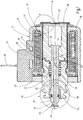
- the in the Fig.1 shown in longitudinal section actuator which is also referred to in the jargon as "actuating or switching magnet", has a designated as a whole with 10 housing with a coil body 12 arranged therein with coil winding 14.
- the pertinent bobbin 12 comprises at least partially a pole tube 16, which is magnetically decoupled from a pole core 20 by means of a separation point 18 in the form of a released position.
- solutions are known in the prior art in which a corresponding separation point is formed by a weld or the like.
- a magnet armature 22 is longitudinally movable in an armature space 24, which cooperates at its one free, front end with a rod-like actuating member 26 for actuating fluid valves (not shown) of conventional design, in particular in the form of pneumatic valves, not shown ,
- the pole core 20 is provided at its free end with a connecting flange 28.
- the connecting flange 28 has on its outer circumference recessed annular grooves for at least partially receiving corresponding elastomer sealing rings and for guiding media streams.
- a Stekerteil 30 is provided, which is preferably fixedly connected via a potting compound 32 with the other housing parts of the housing 10.
- a potting compound 32 With the other housing parts of the housing 10.
- an annular pole plate 34 is inserted, which caulked for their firm grip in the housing 10 with this is (not shown).
- the pole plate 34 includes the outer periphery of the pole core 20, which in this respect via the valve means not shown in its in the Fig.1 shown mounting position is held in the actuator.
- the pole tube 16 is pot-shaped in the manner of a receiving sleeve and the bottom part 36 of the pole tube 16 forms a stop limit for the magnet armature 22 in its direction in the direction of the extent Fig.1 seen extremely right traversing position.
- the potting compound 32 together with bobbin 12 are made of a plastic material, for example polyamide, preferably PA6.
- the potting compound 32 on the top of the actuator engages along its underside in recesses of a cup-shaped housing shell 38, which is also part of the housing 10.
- Both housing shell 38 and magnet armature 22 and pole core 20 and pole plate 34 are made of a metallic material, wherein all parts mentioned may consist of the same material.
- the pole tube 16 is preferably made of a stainless steel material, which may be designed to be magnetically conductive or non-conductive depending on the purpose.
- the armature 22 is in his in the Fig.1 shown actuated position method, ie in the direction of the Fig.1 Seen from a right position to a left, the extent of the operating position after the Fig.1 equivalent.
- the armature 22 takes the rod-shaped actuating member 26, the free end protrudes for an actuation operation on the pneumatic valve, not shown in each of its Verfahrwolfen from the housing 10 and in particular from the pole core 20.
- an energy storage in the form of a compression spring 40 is biased and as soon as the coil winding 14 is kept de-energized, the prestressed compression spring 40 pushes the armature 22 back to its right starting position, in which he can also come into contact with the inside of the bottom part 36 of the pole tube 16.
- the connected valve device In the current-de-energized state, the connected valve device is normally open.
- it could also be provided to move the energy storage in the form of the compression spring 40 in the connected valve device, to cause in such a way the aforementioned return movement for the armature 22 together with actuating member 26.
- a non-stick device 42 which includes the rod-like actuating member 26 with a radial distance, so as to make a decoupling effective.
- the rod-like actuating member 26 is penetrated by a central channel 44 which extends along the longitudinal axis 46 of magnet armature 22 and actuating member 26, which also forms the possible travel axis. Said center channel 44 exits at the two opposite end faces 48, 50 of the actuating part 26 into the environment.
- the center channel 44 opens on the right end face 50 of the actuating part 26 into a free space 52 of the magnet armature 22, the free space 52 in this respect pressure and media leading again opens into the armature space 24.
- a transverse channel 56 is present, which opens with its one end in the center channel 44 and with its other end in a central space 58th exit, which is encompassed by the pole core 20.
- the components center channel 44, cross channel 56, center 58, space 52 and armature space 24 form a kind of pressure compensation system which is connected to the valve unit, not shown, and so far compensated coming from the valve unit pressure media such that the movement of the armature 22 together with actuating member 26th is not affected by any pressure differences.
- the pressure media guided in this way can also effectively support the actuation force to be applied by the magnet armature 22 due to different area ratios.
- the pole core 20 engages with a nose-like annular projection 60 stepped in this area gradation 62 of the magnet armature 22 such that in each displacement position of the magnet armature 22 this is guided within the annular projection 60, so that the size of the separation point 18 each changes according to the direction of travel of the magnet armature 22.
- the rod-like actuating part 26 is formed from a sprayable material, which in particular according to illustration of the Figure 3 is injection-molded in a connection region 64 to the armature 22. If sprues are mentioned here, this includes the usual injection molding, casting and die casting processes.
- the sprayable material of the operating part 26 may basically be any material that can be processed in this way.
- a plastic material is used, in particular a thermoplastically processable plastic.
- Particularly advantageous is the use of polybutylene terephthalate (PBT) has been found, which allows injection molding at melt temperatures of 230 ° C to 270 ° C.
- PBT polybutylene terephthalate
- the plastic material used has the necessary strength and rigidity and the sliding and wear behavior has proven to be very good in practical experiments for the present application.
- the entire actuating part 26 is formed from a sprayable plastic material; But there is also the possibility here, the operating part 26 in the front region of a conventional metallic To form rod material, which is then molded only in the transition region to the armature 22 by means of injectable material.
- FIG 3 is a designated as a whole with 66 injection mold partially and represented by their basic structure.
- the pertinent injection mold 66 is formed in several parts (not shown) and can be so far with their parts to the overall shape as shown in the Figure 3 put together.
- the injection mold 66 of the metallic armature 22 is inserted, which forms the connection region 64 at its one free end side.
- the possible Anspritz Chemistry 68 thus formed is bounded to the outside by the wall of the injection mold 66 and chosen such that this certainly does not project beyond the free end face of the magnet armature 22 in this area.
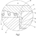
- a circumferential annular groove-like recess 70 is introduced, which in an enlarged view in the Fig.2 is reproduced and forms a kind of undercut design 72, so that the injected plastic material can keep under hooking undercut in the armature 22 along the connecting portion 64 accordingly.
- the armature 22 has a centrally extending central opening 74 which is penetrated by the actuating part 26, wherein, as shown in the Figure 3 a correspondingly inserted mold core 76 enables the pertinent embodiment. Since the center opening 74 exits into the widening free space 52, there is formed a further contact surface as a second Anspritz composition 78 of the armature 22.
- the injection mold 66 after the Figure 3 is formed such that the rod-like actuating member 26 widened radially outward to form the disc-like anti-adhesive device 42 already described.
- the pole core 20 is safely decoupled from the armature 22 and the anti-stick device 42 also forms a kind of stop protection for the armature 22.
- a system stage 80 is introduced, at which the one free end of the force accumulator in the form of the compression spring 40 is supported.
- the actual non-stick device 42 is relieved of the introduction of force of the compression spring 40, which pushes the rod-like actuating member 26 in the direction of the connecting portion 64 of the magnet armature 22 in each case in each Verfahr ein the armature 22.
- the center space 58 tapers to both sides by the rod-like actuating member 26 along two transition regions 82 widens conically in diameter.
- the embodiment of the Figure 4 is in any case modified insofar as in the connecting region 64, the molded plastic material to increase the binding mass kidney-like widening 84, in turn, the non-stick device 42 is an integral part of the operating part 26. Due to the diametrically opposite ring-like recesses 86, which adjoin the kidneys 84 on both sides in the manner of a circle segment, the energy store in the form of the compression spring 40 does not have to rest on the molded plastic material as a whole, but can be supported directly on the metal areas of the magnet armature 22 for improved support ,
- the embodiment according to the Figures 5 corresponds to the basic structure of the embodiment according to the FIGS. 4 ; alone, here is the non-stick device 42 as an anti-adhesive disk via a corresponding intervention point 88 fixedly connected to the magnet armature 22 frontally.
- the compression spring 40 is located with its one end directly to the end face of the magnet armature 22, in the region of the annular gap 90, formed by the intermediate distance from the outer periphery of the fastening part 26 to the inner circumference of the independently formed anti-stick disc 42 of the non-stick device.
- the anti-adhesive device 42 is formed from a Antiklebtopf, which rests with its radial Um chargedsrand on the front side of the armature 22 and otherwise engages with its cylindrically curved bottom part in the center opening 74 of the magnet armature 22.
- the actuating member 26 is located with its injectable plastic material only in the region of the second Anspritz Chemistry 78 directly to the armature 22 and the first Anspritz Chemistry 68 is formed by the system to the top of said anti-stick device 42nd
- Said sealing point 54 is formed from a ring body 92, which is used in a paragraph-like widening 94 at the free end of the pole core 20, in particular there is pressed.
- the ring body 92 has conical insertion aids 96 at its two free ends.
- the ring body 92 is formed from a material with good sealing and sliding properties, which in addition to sprayable plastics such as polyamide, quite non-ferrous metal materials could be used. If particularly good sliding properties are required, a PTFE material can also form the ring body 92.
- the pole core 20 can be at least partially crimped along its free inner area, so that Bördelrandabroughe 98 outwardly form an effective stop limit.
- a sectional configuration of the bead can also be formed circumferentially.
- the pole tube 16 which emerges in the direction of the figures seen on the right edge of the housing shell 38 of the housing 10, provided with a widened and deflected edge 104 which extends so far with a predetermined axial distance to the outer wall of the housing shell 38 .
- the pertinent embodiment forms a kind of floating bearing.
- the extent formed edge 104 forms the transition point between the cylindrical Polrohrwandung 106 and the transverse thereto extending bottom part 36.
- the bottom part 36 is provided in the direction of the armature space 24 with an angled portion 108 which in a right stop position of the armature 22 in whose free space 52 protrudes. Otherwise, the resilient bottom portion 36 forms a stop cushioning for the impinging magnet armature 22, if this is its rightmost displacement position as shown in the Fig.1 occupies.
- edge 104 favors this effect by forming a resilient flexible hinge point.
- edge 104 opens a circulation gap 110, can get into the medium, which in turn benefits the stiffening of the overall system in this area.
- a resiliently resilient return means 112 in the form of an energy storage device, for example formed from components of a plate spring 114 of the in Figure 8 a segment part is shown.
- a single segment disc spring 114 as shown in the Figure 8 could basically come but also a plate spring package or other return means, for example in the form of a conventional coil spring which acts as a compression spring. You could also use a bellows at this point or a prestressed elastomer ring, if its use would be possible at all due to the prevailing temperatures.
- the return means 112 preferably in the form of the plate spring 114, engages with its one end effectively on the free end face of the housing shell 38 and is supported with the other free end of a deflection 116, at which the cylindrical Polrohrwandung 106 in the projecting edge 104th passes.
- the pole tube 16 is formed of a stainless steel material and the used return means 112 also has the advantage that when occurring vibrations to the actuator, the pole tube 16 is decoupled from the housing 10.
- the supernatant selected to the right for the edge 104 with respect to the free end face of the housing shell 38 is selected such that the respective return means 112 with his Can safely attack bias on pole tube 16 and that this space can be arranged on the other housing 10 to save space.
- the said bend 108 also ensures that the pole tube 16 is reinforced in its pertinent bottom portion 36, so that it can not come to a permanent deformation in a possible striking of the armature 22.
- the step-shaped transitional area 122 is caulked inward, along a caulking surface 124 which is offset from the other outer diameter of the pole core 20 in the direction of the pole plate 34.
- the free end of the pole tube 16 is not only axially and radially fixed from both sides by the pole core material caulked in this region, but also kept gas-tight, ie the solution shown here comes between the pole core 20 in the region of its without additional elastomer seal or other sealing system Ring projection 60 and the fixing point at the free end edge of the pole tube 16 from.
- the pertinent actuators are also partially used in the high temperature range, which is basically the elastomeric material damaged by seals, so far as a cost-effective sealing alternative is realized. Due to the arcuate transition region 120, the pole tube is also safely guided without major kinks in the direction of the annular projection 60 on the outer circumference of the pole tube 22, so that no unnecessary material stress for the thin-walled pole tube material occurs in this respect. With regard to these guide paths 126 and the guide centering via the return means 112 at the free end region of the pole tube 16, it is ensured that buckling processes do not occur, which could possibly restrict the free mobility of the magnet armature 22 with its actuating part 26.
- the actuating device according to the invention is determined especially in the low pressure range for the application in pneumatic valves in the high temperature range; with appropriate modification but other applications, especially in hydraulic valves, conceivable.
- the very lightweight actuator has very short switching and response times and it can reach extremely high load changes, which can be in the millions of millions.
Landscapes
- Physics & Mathematics (AREA)
- Electromagnetism (AREA)
- Engineering & Computer Science (AREA)
- Power Engineering (AREA)
- General Engineering & Computer Science (AREA)
- Mechanical Engineering (AREA)
- Magnetically Actuated Valves (AREA)
- Electromagnets (AREA)
Description
- Die Erfindung betrifft eine Betätigungsvorrichtung, insbesondere zum Betätigen von außenseitig anschließbaren Ventilen, mit einem Gehäuse und einem darin angeordneten Spulenkörper mit Spulenwicklung, der zumindest teilweise ein Polrohr umfaßt, an dessen einem freien Ende sich ein Polkern anschließt, mit einem zumindest im Polrohr innerhalb eines Ankerraumes längsverfahrbar geführten Magnetanker, der mit einem Betätigungsteil für das Betätigen des jeweiligen Ventilteils zusammenwirkt, wobei das Polrohr in der Art einer Aufnahmehülse für den Magnetanker ausgebildet ist, die mit ihrem freien Endbereich an einer Festlagerstelle festgelegt ist.
- Durch die
DE 10 2004 051 332 A1 ist eine gattungsgemäße Betätigungsvorrichtung bekannt. Bei der bekannten Lösung ist das Polrohr an seinem einen freien Ende, das aus dem Gehäuse der Betätigungsvorrichtung herausragt, mit einem umgelegten Rand versehen, gegen den der Magnetanker sich in seiner einen endseitigen Verfahrstellung abstützen kann, wobei der Umlegerand eine Mittenöffnung freiläßt, in die ein Druckausgleichskanal des Magnetankers einmündet, der sich auf seiner gegenüberliegenden Seite an dem Polkern abstützen kann, in dessen Richtung insoweit der Druckausgleichskanal auf seiner anderen Seite hin ausmündet. Insoweit ist durch den Spulenkörper und von Gehäuseteilen begrenzt für den nach außen weisenden freien Endrand des Polrohres eine Loslagerstelle gebildet. - Am gegenüberliegenden Ende weist das Polrohr einen in die entgegengesetzte Richtung weisenden Umlegerand geringerer Krümmung auf, mit der es zwischen dem Spulenkörper und dem Polkern sowohl axial als auch radial in einer Festlagerstelle lagefixiert ist. Aufgrund der Umlenkungen zu den freien Rändern des Polrohres hin, das in der Art einer Aufnahmehülse für den längsverfahrbaren Magnetanker ausgebildet ist, ist das Polrohr in der Lage, einen gewissen Toleranzlängenausgleich herzustellen, um dergestalt einen paßgenauen Einbau für die Teile der Betätigungsvorrichtung zu schaffen. Aufgrund der definierten Einspannstelle der Aufnahmehülse als Polrohr an der Festlagerstelle zwischen Polkern und Spulenkörper sind die dahingehenden Toleranzausgleichsmöglichkeiten aber eingeschränkt. Um das Innere der Betätigungsvorrichtung gegenüber der Umgebung abzudichten, ist am Innenumfang der Aufnahmehülse als Polrohr ein Dichtsystem vorhanden, vorzugsweise in Form eines Elastomer-Dichtringes, der in einer Außennut des Polkerns angebracht die Dichtung zwischen dem Polkern und dem Polrohr sicherstellt. Ist der Elastomer-Dichtring nicht richtig eingebaut oder wurde er beim Einbau vergessen, kann es zu einem Versagen der Dichtstelle kommen und das Innere der Betätigungsvorrichtung ist nicht mehr mediendicht gegenüber der Umgebung abgedichtet. Der dahingehende Versagensfall kann auch eintreten, wenn durch lang andauernden Gebrauch das Dichtsystem verschlissen und mithin unbrauchbar geworden ist.
- Um dem Nachteil der eingeschränkten Toleranzausgleichsmöglichkeit zu begegnen, ist in der
DE 10 2005 061 184 A1 bei einer gleichfalls gattungsgemäßen Betätigungsvorrichtung vorgeschlagen worden, den vorstehend genannten Umlegerand des Polrohres als geschlossenes Bodenteil einer Aufnahmehülse auszubilden, das vom Polkern abgestützt mit diesem in Anlage ist, wobei das Bodenteil des Polrohres derart in den Polkern einpaßbar ist, dass es seine Lage beibehält, auch wenn der Magnetanker für eine Betätigung eines an die Betätigungsvorrichtung anschließbaren Ventils sich hin und her bewegt und dabei insbesondere auf das Bodenteil drückt oder sich ziehend von diesem abhebt. Da der Umlegerand nicht mehr, wie vorstehend aufgezeigt, eine ringförmige Durchlaßstelle begrenzt, sondern vielmehr geschlossen ist, ist insoweit auch ein Einsatz für hohe Drücke möglich, da insoweit neben der Druckdichtheit auch ein steifes belastbares Polrohrsystem ausgebildet ist. - Durch die definierte Anlage des Bodenteils des Polrohres am Polkern ist eine Art Fixierung erreicht, die an anderer Stelle des Polrohres in einem weit gezogenen Bereich die Möglichkeit eines Toleranzausgleichs eröffnet. Hierbei ist vorgesehen, dass das Polrohr an seinem freien Ende in einen sickenförmigen Flansch ausmündet, der sich an dem Gehäuse der Betätigungsvorrichtung abstützt. Das Sickenteil des Flansches ist dabei in der Art einer Rundsicke ausgebildet, was es ermöglicht, einen freien Endbereich des sickenförmigen Flansches zwischen Gehäuse der Betätigungsvorrichtung und Gehäuseteile des sich anschließenden Ventilkörpers durch Klemmung lagezufixieren, und aufgrund des elastisch nachgiebigen Sickenkörpers ist eine Art Gelenkstelle realisiert, längs der sich insbesondere in axialer Richtung das Polrohr mit seiner Einbaulänge innerhalb des Spulenkörpers und des Polkerns anpassen kann. Zwischen dem elastisch nachgiebigen Sickenkörper und dem angeschlossenen Ventilgehäuse des Ventils ist wiederum ein Elastomer-Dichtring angeordnet, der eine mediendichte Abdichtung zwischen dem Inneren von Betätigungsvorrichtung nebst Ventil gegenüber der Umgebung sicherstellen soll. Auch dieses bekannte Dichtsystem kann zu den bereits beschriebenen Nachteilen der fehlenden Mediendichtheit führen.
- Ausgehend von diesem Stand der Technik liegt der Erfindung die Aufgabe zugrunde, die bekannten Lösungen unter Beibehalten ihrer Vorteile, nämlich insbesondere einen funktionssicheren, lang andauernden Betätigungsbetrieb sicherzustellen, dahingehend weiter zu verbessern, dass mit geringern, konstruktiven Aufwand und mithin kostengünstig eine mediendichte Trennung von dem Inneren der Betätigungsvorrichtung gegenüber der Umgebung erreicht ist. Eine dahingehende Aufgabe löst eine Betätigungsvorrichtung mit den Merkmalen des Patentanspruches 1 in seiner Gesamtheit.
- Dadurch, dass gemäß dem kennzeichnenden Teil des Patentanspruches 1 die Festlagerstelle aus zwei Anlageteilen des Polkerns gebildet ist, die zwischen sich einen Aufnahmespalt begrenzen, in dem der freie Endbereich der Aufnahmehülse geklemmt festgelegt ist, ist eine mediendichte Trennung zwischen dem Inneren der Betätigungsvorrichtung und der Umgebung erreicht. Für eine mediendichte Trennung trägt auch mit dazu bei, dass die Aufnahmehülse in ihrer bevorzugten Ausgestaltung topfartig ausgebildet ist und mithin über ein in sich geschlossenes Bodenteil verfügt. Das gesamte Polrohr braucht im Hinblick auf die spezielle Ausgestaltung der Festlagerstelle entlang des Innenumfanges kein weiteres Dichtsystem, das insoweit auch nicht versagen oder vergessen werden kann. Im übrigen spart die dahingehende Lösung unter Wegfall des zusätzlich benötigten Dichtsystems für das Polrohr Herstell- und Montagekosten.
- Bei einer bevorzugten Ausführungsform der erfindungsgemäßen Betätigungsvorrichtung ist das eine Anlageteil aus einer Verengungsstelle des Polkerns gebildet, die im Durchmesser kleiner ist als der sonstige Außendurchmesser des Polkerns im Bereich der Festlagerstelle, wobei der hieraus entstehende stufenförmige Übergangsbereich eine Stemmfläche als das weitere Anlageteil des Polkerns ausbildet. Demgemäß läßt sich eine medien-, insbesondere gasdichte Festlagerstelle erreichen, indem man in einem ersten Herstellschritt den eingebördelten Endrand des Polrohres in die Verengungsstelle einlegt und in einem zweiten Schritt den stufenförmigen Übergangsbereich über die Außenseite des Polrohres darüberliegend verstemmt, so dass eine form- und kraftschlüssige Verbindung erreicht ist. Die dahingehenden Herstellschritte lassen sich in kostengünstiger Weise realisieren.
- Bei einer weiteren bevorzugten Ausführungsform der erfindungsgemäßen Betätigungsvorrichtung ist vorgesehen, dass an einer Loslagerstelle für die Aufnahmehülse an dieser ein Rückstellmittel angreift, das eine Kraft auf die Aufnahmehülse ausübt, die von der Festlagerstelle weggerichtet ist. Hierdurch läßt sich in einem sehr weit gezogenen Rahmen ein Toleranzausgleich für das Gesamtsystem erreichen, wobei die dahingehende Ausgleichsgröße sich über eine geeignete Wahl des Rückstellmittels vorgeben läßt. Unabhängig von etwaigen Herstelltoleranzen der einzelnen Baukomponenten der Betätigungsvorrichtung ist somit die damit einhergehende Toleranz über das an der Aufnahmehülse angreifende Rückstellmittel kompensierbar und insoweit individuell ausgleichbar.
- Obwohl das Rückstellmittel derart versucht, das Pol rohr aus der Festlagerstelle zu ziehen, berührt dies die mediendichte Klemmung über das verstemmte Polkernmaterial nicht, da in der Art eines Gegen- oder Widerlagers der freie Endbereich des Polrohres über einen bogenförmigen Übergangsbereich aus der Verengungsstelle heraus in eine Führungsstrecke überführt ist, die mit einem gegenüber dem Außendurchmesser der Verengungsstelle verbreiterten Durchmesser über eine längere Wegstrecke eine Permanentanlage zwischen Polrohr und Polkern in diesem Bereich vorsieht und soweit eine Entlastung für die Festlagerstelle mit gewährleistet. Durch die genannte axial verlaufende Führungsstrecke, die in den gebogenen Übergangsbereich übergeht, ist darüber hinaus eine längere Dichtstrecke realisiert, die als Austrittshindernis für das jeweilige Medium auch in Form von Gas wirkt.
- Bei einer weiteren, besonders bevorzugten Ausführungsform der erfindungsgemäßen Betätigungsvorrichtung ist die Festlagerstelle für die Aufnahmehülse an ihrem freien Endrand vorgesehen und mit dem Polkern, wie aufgezeigt, entsprechend verstemmt. Die Loslagerstelle ist am gegenüberliegenden Ende des Polrohres im Bereich des geschlossenen Bodenteils angeordnet, insbesondere an der Stelle, an der das Polrohr aus dem Gehäuse der Betätigungsvorrichtung austritt und die Lagerung ist durch den Spulenkörper und/oder durch die Gehäuseteile erreicht, die von dem Polrohr durchgriffen sind. Durch den Angriff des Rückstellmittels, vorzugsweise in Form eines Energiespeichers, beispielsweise in der Art einer Tellerfeder an der Loslagerstelle, wird die Aufnahmehülse mit ihrem Innenumfang entsprechend langgezogen und gleicht etwaige Unebenheiten entlang ihres Innenumfanges aus. Auch wird insoweit die Aufnahmehülse als Polrohr permanent unter Zugspannung gehalten, so dass eine dichtende Anlage zwischen Innenumfang des Polrohres und dem Außenumfang des Polkerns entlang der genannten Führungsstrecke erreicht ist. Da insbesondere die Elastomerteile eines Dichtsystems unter Anlage mit metallischen Wandteilen Schaden nehmen können, ist durch das Weglassen eines dahingehenden Dichtsystems im metallischen Wandbereich die angestrebte Mediendichtheit sichergestellt.
- Weitere vorteilhafte Ausgestaltungen der erfindungsgemäßen Betätigungsvorrichtung sind Gegenstand der sonstigen Unteransprüche.
- Im folgenden wird die erfindungsgemäße Ausführungsform anhand von Ausführungsbeispielen nach der Zeichnung näher erläutert. Dabei zeigen in prizipieller und nicht maßstäblicher Darstellung die
- Fig. 1
- in der Art eines Längsschnittes die Betätigungsvorrichtung als Ganzes, jedoch ohne angeschlossene Ventileinrichtung;
- Fig.2
- einen vergrößerten Ausschnitt gemäß Kreisdarstellung D in
Fig.1 ; - Fig.3
- in der Art eines Längsschnittes einen Teil der Herstellform betreffend den Anspritzvorgang eines Betätigungsteils an den Magnetanker der Betätigungsvorrichtung;
- Fig.4a,4b und 4c
- im Längsschnitt, in perspektivischer Draufsicht sowie in Vorderansicht eine gegenüber den
Fig.1 bis 3 geänderte zweite Ausführungsform einer Anspritzlösung; - Fig. 5a,5b und 5c
- in entsprechender Darstellung zu den
Fig.4a, 4b und 4c eine dritte Ausführungsform einer Anspritzlösung; - Fig.6a,6b,6c
- eine zu den
Fig.4a, 4b und 4c entsprechende Darstellung einer vierten Ausführungsform der Anspritzlösung; - Fig.7
- einen vergrößerten Ausschnitt gemäß Kreisdarstellung A in
Fig.1 ; - Fig.8
- einen vergrößerten Ausschnitt gemäß Kreisdarstellung B in
Fig.1 ; - Fg.9
- einen vergrößerten Ausschnitt gemäß Kreisdarstellung C in
Fig.1 ; - Fig.10 und 11
- in der Art einer Längsschnittdarstellung die einzelnen Herstellschritte für die Detaillösung gemäß Kreisdarstellung C nach
Fig.9 . - Die in der
Fig.1 im Längsschnitt dargestellte Betätigungsvorrichtung, die man in der Fachsprache auch mit "Betätigungs- oder Schaltmagnet" bezeichnet, weist ein als Ganzes mit 10 bezeichnetes Gehäuse auf mit einem darin angeordneten Spulenkörper 12 mit Spulenwicklung 14. Der dahingehende Spulenkörper 12 umfaßt zumindest teilweise ein Polrohr 16, das mittels einer Trennstelle 18 in Form einer freigelassenen Stelle magnetisch von einem Polkern 20 im wesentlichen entkoppelt ist. Es sind im Stand der Technik aber auch Lösungen (nicht dargestellt) bekannt, bei denen eine korrespondierende Trennstelle durch eine Schweißnaht od. dgl. gebildet ist. Längs des Polrohres 16 ist ein Magnetanker 22 in einem Ankerraum 24 längsverfahrbar geführt, der an seinem einen freien, stirnseitigen Ende mit einem stangenartigen Betätigungsteil 26 zusammenwirkt zum Betätigen von Fluidventilen (nicht dargestellt) üblicher Bauart, insbesondere in Form von nicht näher dargestellten Pneumatik-Ventilen. Zum Anschließen eines dahingehenden Ventils ist der Polkern 20 an seinem freien Ende mit einem Anschlußflansch 28 versehen. Der Anschlußflansch 28 weist an seinem Außenumfang vertiefte Ringnuten auf zur zumindest teilweisen Aufnahme von entsprechenden Elastomer-Dichtringen und zum Führen von Medienströmen. - Zum Bestromen der Spulenwicklung 14 des Spulenkörpers 12, die bevorzugt aus mindestens einem leitfähigen Kupferdraht besteht, ist ein Stekerteil 30 vorgesehen, das vorzugsweise über eine Vergußmasse 32 mit den sonstigen Gehäuseteilen des Gehäuses 10 fest verbunden ist. In Blickrichtung auf die
Fig.1 gesehen ist auf der linken Seite und nach außen hin mit der Vergußmasse 32 abschließend eine ringförmigen Polplatte 34 eingesetzt, die für ihren festen Halt im Gehäuse 10 mit diesem entsprechend verstemmt ist (nicht dargestellt). Im übrigen umfaßt die Polplatte 34 den Außenumfang des Polkerns 20, der insoweit über die nicht näher dargestellte Ventileinrichtung in seiner in derFig.1 gezeigten Einbaulage in der Betätigungsvorrichtung gehalten ist. Das Polrohr 16 ist topfartig in der Art einer Aufnahmehülse ausgebildet und das Bodenteil 36 des Polrohres 16 bildet insoweit eine Anschlagbegrenzung für den Magnetanker 22 in seiner in Blickrichtung auf dieFig.1 gesehen äußerst rechten Verfahrstellung aus. Die Vergußmasse 32 nebst Spulenkörper 12 bestehen aus einem Kunststoffmaterial, beispielsweise Polyamid, vorzugsweise aus PA6. Die Vergußmasse 32 auf der Oberseite der Betätigungsvorrichtung greift entlang ihrer Unterseite in Ausnehmungen eines topfartigen Gehäusemantels 38 ein, der gleichfalls Bestandteil des Gehäuses 10 ist. Sowohl Gehäusemantel 38 als auch Magnetanker 22 sowie Polkern 20 und Polplatte 34 bestehen aus einem metallischen Material, wobei alle genannten Teile aus demselben Material bestehen können. Das Polrohr 16 ist bevorzugt aus einem Edelstahlmaterial erstellt, das in Abhängigkeit des Einsatzzweckes magnetisch leitend oder nichtleitend ausgebildet sein kann. - Wird über das Steckerteil 30 die Spulenwicklung 14 und mithin die Spule bestromt, wird der Magnetanker 22 in seine in der
Fig.1 gezeigte betätigte Stellung verfahren, also in Blickrichtung auf dieFig.1 gesehen von einer rechten Stellung in eine linke, die insoweit der Betätigungsstellung nach derFig.1 entspricht. Bei der dahingehenden Verfahrbewegung nimmt der Magnetanker 22 das stangenförmige Betätigungsteil 26 mit, dessen freies Ende für einen Betätigungsvorgang an dem nicht näher dargestellten PneumatikVentil in jeder seiner Verfahrstellungen aus dem Gehäuse 10 und insbesondere aus dem Polkern 20 herausragt. Bei der dahingehenden Verfahrbewegung des Magnetankers 22 in Blickrichtung auf dieFig.1 gesehen nach links wird ein Energiespeicher in Form einer Druckfeder 40 vorgespannt und sobald die Spulenwicklung 14 stromlos gehalten ist, schiebt die vorgespannte Druckfeder 40 den Magnetanker 22 in seine rechte Ausgangsstellung zurück, bei der er auch in Anlage mit der Innenseite des Bodenteils 36 des Polrohres 16 kommen kann. Im dahingehend stromlosen Zustand ist die angeschlossene Ventileinrichtung stromlos offengeschaltet. Bei einer geänderten Ausführungsform (nicht dargestellt) der erfindungsgemäßen Betätigungsvorrichtung könnte es auch vorgesehen sein, den Energiespeicher in Form der Druckfeder 40 in die angeschlossene Ventileinrichtung zu verlegen, um dergestalt die angesprochene Rückstellbewegung für den Magnetanker 22 nebst Betätigungsteil 26 zu veranlassen. - Selbst bei Wegfall des Stromes kann es aber aufgrund von Restmagnetismusvorgängen im Polkern 20 und in der Polplatte 34 dazu kommen, dass der Magnetanker 22 mit seiner einen freien Stirnseite an der ihm zugewandten benachbarten Stirnseite des Polkerns 20 haften bleibt. Um dies zu vermeiden, wird zwischen die beiden Stirnseiten innerhalb des Ankerraumes 22 eine Antihafteinrichtung 42 eingesetzt, die mit einem radialen Abstand das stangenartige Betätigungsteil 26 umfaßt, um so wirksam eine Entkopplung vorzunehmen. Das stangenartige Betätigungsteil 26 ist von einem Mittenkanal 44 durchgriffen, der sich entlang der Längsachse 46 von Magnetanker 22 und Betätigungsteil 26 erstreckt, die insoweit auch die mögliche Verfahrachse bildet. Der genannte Mittenkanal 44 tritt an den beiden gegenüberliegenden Stirnseiten 48,50 des Betätigungsteils 26 in die Umgebung aus. Insbesondere mündet der Mittenkanal 44 auf der rechten Stirnseite 50 des Betätigungsteils 26 in einen Freiraum 52 des Magnetankers 22 aus, wobei der Freiraum 52 insoweit druck- und medienführend wiederum in den Ankerraum 24 ausmündet. Im Bereich zwischen einer Dichtungsstelle 54, die insoweit auch eine Führung ausbildet für das vordere Ende der Betätigungsstange 26, und dem Magnetanker 22 ist ein Querkanal 56 vorhanden, der mit seinem einen Ende in den Mittenkanal 44 ausmündet und mit seinem anderen Ende in einen Mittenraum 58 austritt, der von dem Polkern 20 umfaßt ist.
- Die Komponenten Mittenkanal 44, Querkanal 56, Mittenraum 58, Freiraum 52 sowie Ankerraum 24 bilden eine Art Druckausgleichssystem aus, das an die nicht näher dargestellte Ventileinheit angeschlossen ist und insofern von der Ventileinheit kommende Druckmedien dergestalt kompensiert, dass die Verfahrbewegung des Magnetankers 22 nebst Betätigungsteil 26 durch etwaige Druckdifferenzen nicht beeinträchtigt ist. Gegebenenfalls können die derart geführten Druckmedien auch aufgrund unterschiedlicher Flächenverhältnisse die aufzubringende Betätigungskraft seitens des Magnetankers 22 wirksam mit unterstützen. Im Bereich der Trennstelle 18 übergreift der Polkern 20 mit einem nasenartigen Ringvorsprung 60 die in diesem Bereich abgesetzte Stufung 62 des Magnetankers 22 derart, dass in jeder Verfahrstellung des Magnetankers 22 dieser innerhalb des Ringvorsprunges 60 geführt ist, so dass sich die Größe der Trennstelle 18 je nach Verfahrrichtung des Magnetankers 22 ändert.
- Das stangenartige Betätigungsteil 26 ist aus einem spritzbaren Material gebildet, das insbesondere gemäß Darstellung nach der
Fig.3 in einem Verbindungsbereich 64 an den Magnetanker 22 angespritzt ist. Sofern hier von Anspritzen die Rede ist, schließt dies die üblichen Spritz-, Gieß- und Druckgießverfahren mit ein. Das spritzbare Material des Betätigungsteils 26 kann dem Grunde nach jedes derart verarbeitbare Material sein. Vorzugsweise wird jedoch ein Kunststoffmaterial eingesetzt, insbesondere ein thermoplastisch verarbeitbarer Kunststoff. Als besonders vorteilhaft hat sich der Einsatz von Polybutylenterephthalat (PBT) erwiesen, das ein Spritzgießen bei Massetemperaturen von 230°C bis 270°C erlaubt. Das eingesetzte Kunststoffmaterial weist die notwendige Festigkeit und Steifigkeit auf und das Gleit- und Verschleißverhalten hat sich in praktischen Versuchen für die hier vorliegende Anwendung als sehr gut erwiesen. Im vorliegenden Ausführungsbeispiel ist das gesamte Betätigungsteil 26 aus einem spritzbaren Kunststoffmaterial gebildet; es besteht hier aber auch die Möglichkeit, das Betätigungsteil 26 im vorderen Bereich aus einem üblichen metallischen Stangenwerkstoff zu bilden, der dann nur im Übergangsbereich zum Magnetanker 22 mittels spritzbarem Material angespritzt ist. - In der
Fig.3 ist eine als Ganzes mit 66 bezeichnete Spritzgußform teilweise und von ihrem prinzipiellen Aufbau her dargestellt. Für einen Entformvorgang ist die dahingehende Spritzgußform 66 mehrteilig ausgebildet (nicht dargestellt) und läßt sich insoweit mit ihren Teilen zur Gesamtform gemäß der Darstellung nach derFig.3 zusammensetzen. In die Spritzgußform 66 wird der metallische Magnetanker 22 eingelegt, der an seiner einen freien Stirnseite den Verbindungsbereich 64 ausbildet. Die derart gebildete mögliche Anspritzfläche 68 ist nach außen hin durch die Wandung der Spritzgußform 66 begrenzt und derart gewählt, dass diese jedenfalls nicht über die freie Stirnseite des Magnetankers 22 in diesem Bereich vorsteht. Ferner ist innerhalb der Anspritzfläche 68 in die freie Stirnseite des Magnetankers 22 eine umlaufende ringnutartige Vertiefung 70 eingebracht, die in vergrößerter Darstellung in derFig.2 wiedergegeben ist und eine Art Hinterschnittgestaltung 72 ausbildet, damit das eingespritzte Kunststoffmaterial sich entsprechend unterhakend im Hinterschnitt im Magnetanker 22 entlang des Verbindungsbereichs 64 halten kann. Weiter weist der Magnetanker 22 eine zentral verlaufende Mittenöffnung 74 auf, die von dem Betätigungsteil 26 durchgriffen ist, wobei gemäß der Darstellung nach derFig.3 ein entsprechend eingelegter Formkern 76 die dahingehende Ausgestaltung ermöglicht. Da die Mittenöffnung 74 in den sich erweiternden Freiraum 52 austritt, ist dort eine weitere Anlagefläche als zweite Anspritzfläche 78 des Magnetankers 22 ausgebildet. Im Bereich der zweiten Anspritzfläche 78 übergreift das Kunststoffmaterial des Befestigungsteils 26 die insoweit gebildete Verbreiterungsstufe, so dass in beiden Verfahrrichtungen des Magnetankers 22 eine sichere Verankerung des Betätigungsteils 26 über den Anspritzvorgang gewährleistet ist. - Die Spritzgußform 66 nach der
Fig.3 ist derart ausgebildet, dass das stangenartige Betätigungsteil 26 sich radial nach außen hin verbreitert unter Ausbildung der bereits beschriebenen scheibenartigen Antihafteinrichtung 42. Insoweit ist der Polkern 20 vom Magnetanker 22 sicher entkoppelt und die Antihafteinrichtung 42 bildet auch eine Art Anschlagschutz für den Magnetanker 22 aus. Wie insbesondere dieFig.2 zeigt, ist zwischen der scheibenförmigen Antihafteinrichtung 42 und der sonstigen Umfassungsfront des Betätigungsteils 26 eine Anlagestufe 80 eingebracht, an der sich das eine freie Ende des Kraftspeichers in Form der Druckfeder 40 abstützt. Insoweit ist die eigentliche Antihafteinrichtung 42 von der Krafteinleitung der Druckfeder 40 entlastet, die im übrigen in jeder Verfahrstellung des Magnetankers 22 das stangenartige Betätigungsteil 26 in Richtung des Verbindungsbereiches 64 des Magnetankers 22 drückt. Wie sich des weiteren aus denFig.1 und3 ergibt, verjüngt sich der Mittenraum 58 zu beiden Seiten hin, indem das stangenartige Betätigungsteil 26 entlang von zwei Übergangsbereichen 82 sich im Durchmesser konisch verbreitert. - Die Ausführungsform nach der
Fig.4 ist jedenfalls insoweit abgeändert, als im Verbindungsbereich 64 das angespritzte Kunststoffmaterial zur Erhöhung der Anbindungsmasse nierenartige Verbreiterungen 84 aufweist, wobei wiederum die Antihafteinrichtung 42 einstückiger Bestandteil des Betätigungsteils 26 ist. Durch die diametral einander gegenüberliegenden ringartigen Vertiefungsstellen 86, die sich kreissegmentartig an die Nieren 84 beidseits anschließen, braucht der Energiespeicher in Form der Druckfeder 40 nicht insgesamt auf dem angespritzten Kunststoffmaterial aufzuliegen, sondern kann sich für eine verbesserte Abstützung an den Metallbereichen des Magnetankers 22 direkt abstützen. - Die Ausführungsform nach den
Figuren 5 entspricht vom grundsätzlichen Aufbau her der Ausführungsform nach denFiguren 4 ; allein ist hier die Antihafteinrichtung 42 als Antiklebscheibe über eine entsprechende Eingreifstelle 88 mit dem Magnetanker 22 stirnseitig fest verbunden. Im dahingehenden Fall liegt die Druckfeder 40 mit ihrem einen Ende direkt an der Stirnseite des Magnetankers 22 an, und zwar im Bereich des Ringspaltes 90, gebildet durch den Zwischenabstand von Außenumfang des Befestigungsteils 26 zum Innenumfang der eigenständig ausgebildeten Antiklebscheibe der Antihafteinrichtung 42. - Bei der Ausführungsform nach den
Fig.6 wiederum ist die Antihafteinrichtung 42 aus einem Antiklebtopf gebildet, der mit seinem radialen Umfassungsrand an der Stirnseite des Magnetankers 22 anliegt und ansonsten mit seinem zylindrisch eingewölbten Bodenteil in die Mittenöffnung 74 des Magnetankers 22 eingreift. Insoweit liegt das Betätigungsteil 26 mit seinem anspritzbaren Kunststoffmaterial nur im Bereich der zweiten Anspritzfläche 78 direkt am Magnetanker 22 an und die erste Anspritzfläche 68 ist gebildet durch die Anlage an die Oberseite der genannten Antihafteinrichtung 42. - Die Darstellung nach der
Fig.7 zeigt die Betätigungsvorrichtung mit der Dichtungsstelle 54, die den Mittenraum 58 gegenüber dem freien Umgebungsraum nach außen hin abdichtet, in den das freie Ende des Betätigungsteils 26 hineinragt. Die genannte Dichtungsstelle 54 ist aus einem Ringkörper 92 gebildet, der in eine absatzartige Verbreiterung 94 am freien Ende des Polkerns 20 eingesetzt, insbesondere dort eingepreßt ist. Für den dahingehenden Einpreßvorgang weist der Ringkörper 92 zu seinen beiden freien Enden hin konische Einführhilfen 96 auf. Der Ringkörper 92 ist aus einem Werkstoff mit guten Dicht- und Gleiteigenschaften gebildet, wobei neben spritzbaren Kunststoffen, wie Polyamid, auch durchaus Buntmetallmaterialien zum Einsatz kommen könnten. Sofern besonders gute Gleiteigenschaften verlangt werden, kann auch ein PTFE-Werkstoff den Ringkörper 92 ausbilden. Damit der Ringkörper 92 sicher in der Aufnahme im Polkern 20 verbleibt, kann darüber hinaus der Polkern 20 längs seines freien Innenbereiches zumindest teilweise eingebördelt werden, so dass Bördelrandabschnitte 98 nach außen hin eine wirksame Anschlagbegrenzung ausbilden. Anstelle einer abschnittsweisen Ausgestaltung kann der Bördelrand auch umlaufend ausgebildet sein. - Wie weiter die Darstellung nach der
Fig.7 verdeutlicht, ist in eine Ringnut 100 ein Elastomerdichtring 102 eingebracht, der insoweit eine Abdichtung zwischen Mittenraum 58 und der freien Umgebung mit sicherstellt. Darüber hinaus ist zwischen Ringnut 100 und benachbartem Übergangsbereich 82 des Betätigungsteils 26 der Durchmesser des Betätigungsteils verbreitert und insoweit in direkter Gleitanlage mit der Innenseite des vorzugsweise als Preßhülse ausgebildeten Ringkörpers 92, was zum einen eine zusätzliche Abdichtung neben dem Elastomerdichtring 102 ergibt und im übrigen eine exakte endseitige Führung für das Betätigungsteil 26 sicherstellt entlang der Längs- oder Verfahrachse 46. Auf der abgewandten Seite zu dem Übergangsbereich 82 ist hingegen der Außendurchmesser des Betätigungsteils 26 verringert, um so einen hemmfreien Betrieb sicherzustellen und den Einfahrvorgang des Betätigungsteils 26 an der Stelle des Übergangs zum Ringkörper 92 nicht zu beeinträchtigen. - Wie insbesondere die
Fig.8 in Verbindung mit derFig.1 zeigt, ist das Polrohr 16, das in Blickrichtung auf die Figuren gesehen am rechten Rand aus dem Gehäusemantel 38 des Gehäuses 10 austritt, mit einem verbreiterten und umgelenkten Rand 104 versehen, der insoweit sich mit einem vorgebbaren axialen Abstand zu der Außenwand des Gehäusemantels 38 erstreckt. Die dahingehende Ausgestaltung bildet eine Art Loslagerstelle aus. Der insoweit gebildete Rand 104 bildet die Übergangsstelle aus zwischen der zylindrischen Polrohrwandung 106 und dem quer dazu verlaufenden Bodenteil 36. Zu seiner Mitte hin ist das Bodenteil 36 in Richtung des Ankerraums 24 mit einer Abkröpfung 108 versehen, die in einer rechten Anschlagstellung des Magnetankers 22 in dessen Freiraum 52 hineinragt. Ansonsten bildet das federelastisch nachgiebige Bodenteil 36 eine Anschlagdämpfung für den auftreffenden Magnetanker 22 aus, sofern dieser seine ganz rechte Verfahrstellung gemäß der Darstellung nach derFig.1 einnimmt. - Der insoweit umgelegte Rand 104 begünstigt diesen Effekt durch Ausbilden einer federelastisch nachgiebigen Gelenkstelle. In den derart gebildeten Rand 104 mündet ein Umlaufspalt 110 ein, in den Medium gelangen kann, was wiederum der Aussteifung des Gesamtsystems in diesem Bereich zugute kommt. Von besonderem Vorteil ist aber, dass für das Polrohr 16 in jedem Temperaturzustand ein Toleranzausgleich geschaffen ist durch ein federelastisch nachgiebiges Rückstellmittel 112 in Form eines Energiespeichers, beispielsweise gebildet aus Bestandteilen einer Tellerfeder 114, von der in der
Fig.8 ein Segmentteil dargestellt ist. Anstelle einer einzelnen Segment-Tellerfeder 114 gemäß der Darstellung nach derFig.8 könnte dem Grunde nach aber auch ein Tellerfederpaket treten oder ein sonstiges Rückstellmittel, beispielsweise in Form einer üblichen Spiralfeder, die als Druckfeder wirkt. Auch könnte man an dieser Stelle einen Federbalg einsetzen oder einen vorgespannten Elastomerring, sofern dessen Einsatz aufgrund der herrschenden Temperaturen überhaupt möglich wäre. - Das Rückstellmittel 112, vorzugsweise in Form der Tellerfeder 114, greift mit seinem einen Ende wirksam an der freien Stirnseite des Gehäusemantels 38 an und stützt sich mit dem anderen freien Ende an einem Umlenkbereich 116 ab, an dem die zylindrische Polrohrwandung 106 in den vorkragenden Rand 104 übergeht. Im Hinblick auf ein hohes Maß an Korrosionsbeständigkeit ist das Polrohr 16 aus einem Edelstahlmaterial gebildet und das eingesetzte Rückstellmittel 112 hat auch noch den Vorteil, dass bei auftretenden Vibrationen an der Betätigungsvorrichtung das Polrohr 16 gegenüber dem Gehäuse 10 entkoppelt ist. Der nach rechts hin gewählte Überstand für den Rand 104 gegenüber der freien Stirnfläche des Gehäusemantels 38 ist derart gewählt, dass das jeweilige Rückstellmittel 112 mit seiner Vorspannung sicher am Polrohr 16 angreifen kann und dass dieses dennoch Bauraum sparend an dem sonstigen Gehäuse 10 anordenbar ist. Die genannte Abkröpfung 108 stellt darüber hinaus sicher, dass das Polrohr 16 in seinem dahingehenden Bodenteilbereich 36 verstärkt ist, so dass es bei einem etwaigen Anschlagen des Magnetankers 22 nicht zu bleibenden Verformungen kommen kann.
- Die Lösung nach den
Fig.9 bis 11 zeigt nun noch die linke Anbindungsstelle des Polrohres 16 am stationär angeordneten Polkern 20 in der Art einer Festlagerstelle. Hierfür weist der Polkern 20 in Richtung seines Ringvorsprunges 60 eine ringnutartige Verengungsstelle 118 auf, die in einem bogenförmigen Übergangsbereich 120 in den sonstigen Außendurchmesser des Polrohres 20 in Richtung des Ringvorsprunges 60 übergeht (vgl.Fig.1 ).Fig. 10 zeigt dabei, dass der dem bogenförmigen Übergangsbereich 120 abgewandte stufenförmige Übergangsbereich 122 zunächst unverformt ist und insoweit nur einen Anstoßbereich für das freie Ende des insoweit eingestemmten oder eingebördelten freien Endrandes des Polrohres 16 bildet. Ist dieser Herstellschritt insoweit vollzogen, wird gemäß der Darstellung nach derFig.1 in einem zweiten Herstellschritt der stufenförmige Übergangsbereich 122 nach innen verstemmt, und zwar entlang einer Stemmfläche 124, die gegenüber dem sonstigen Außendurchmesser des Polkerns 20 in Richtung zur Polplatte 34 abgesetzt ist. Derart ist das freie Ende des Polrohres 16 von beiden Seiten her durch das in diesem Bereich verstemmte Polkernmaterial nicht nur axial und radial festgelegt, sondern auch gasdicht gehalten, d.h. die hier aufgezeigte Lösung kommt ohne zusätzliche Elastomerdichtung oder einem sonstigen Dichtsystem zwischen Polkern 20 im Bereich seines Ringvorsprunges 60 und der Festlegestelle am freien Endrand des Polrohres 16 aus. - Da die dahingehenden Betätigungsvorrichtungen auch teilweise im Hochtemperaturbereich eingesetzt werden, was grundsätzlich das Elastomermaterial von Dichtungen schädigt, ist insoweit eine kostengünstige Abdichtungsalternative realisiert. Durch den bogenförmigen Übergangsbereich 120 ist darüber hinaus das Polrohr ohne größere Knickstellen in Richtung des Ringvorsprunges 60 am Außenumfang des Polrohres 22 sicher geführt, so dass auch insoweit keine unnötige Materialbeanspruchung für das dünnwandige Polrohrmaterial auftritt. Im Hinblick auf diese Führungsstrekke 126 und die Führungszentrierung über das Rückstellmittel 112 am freien Endbereich des Polrohres 16 ist sichergestellt, dass es nicht zu Beulvorgängen kommt, die gegebenenfalls die freie Bewegbarkeit des Magnetankers 22 mit seinem Betätigungsteil 26 einschränken könnten.
- Die erfindungsgemäße Betätigungsvorrichtung ist insbesondere im Niederdruckbereich für den Einsatzbereich bei Pneumatik-Ventilen auch im Hochtemperaturbereich bestimmt; bei entsprechender Modifizierung sind aber auch andere Anwendungen, insbesondere bei Hydraulikventilen, denkbar. Die sehr leichtgewichtige Betätigungsvorrichtung weist sehr kurze Schalt- und Reaktionszeiten auf und es lassen sich ausgesprochen hohe Lastwechsel erreichen, die im mehrstelligen Millionenbereich liegen können.
Claims (10)
- Betätigungsvorrichtung, insbesondere zum Betätigen von außenseitig anschließbaren Ventilen, mit einem Gehäuse (10) und einem darin angeordneten Spulenkörper (12) mit Spulenwicklung (14), der zumindest teilweise ein Polrohr (16) umfaßt, an dessen einem freien Ende sich ein Polkern (20) anschließt, mit einem zumindest im Polrohr (16) innerhalb eines Ankerraumes (24) längsverfahrbar geführten Magnetanker (22), der mit einem Betätigungsteil (26) für das Betätigen des jeweiligen Ventilteils zusammenwirkt, wobei das Polrohr (16) in der Art einer Aufnahmehülse für den Magnetanker (22) ausgebildet ist, die mit ihrem freien Endbereich an einer Festlagerstelle festgelegt ist, dadurch gekennzeichnet, dass die Festlagerstelle aus zwei Anlageteilen (118,124) des Polkerns (20) gebildet ist, die zwischen sich einen Aufnahmespalt begrenzen, in dem der freie Endbereich der Aufnahmehülse geklemmt festgelegt ist.
- Betätigungsvorrichtung nach Anspruch 1, dadurch gekennzeichnet, dass das eine Anlageteil aus einer Verengungsstelle (118) des Polkerns (20) gebildet ist, die im Durchmesser kleiner ist als der sonstige Außendurchmesser des Polkerns (20) im Bereich der Festlagerstelle und dass der hieraus entstehende stufenförmige Übergangsbereich (122) eine Stemmfläche (124) als das weitere Anlageteil des Polkerns (20) ausbildet.
- Betätigungsvorrichtung nach Anspruch 1 oder 2, dadurch gekennzeichnet, dass an einer Loslagerstelle (116) für die Aufnahmehülse an dieser ein Rückstellmittel (112) angreift, das eine Kraft auf die Aufnahmehülse ausübt, die von der Festlagerstelle (118,124) weggerichtet ist.
- Betätigungsvorrichtung nach Anspruch 3, dadurch gekennzeichnet, dass die Aufnahmehülse außerhalb des Gehäuses (10) angeordnet ein Bodenteil (36) aufweist, das gegenüber dem Außendurchmesser der Aufnahmehülse verbreitert ist und insoweit an der Stelle der Durchmesseränderung einen Umlenkbereich (116) aufweist, an dem das Rückstellmittel (112) angreift.
- Betätigungsvorrichtung nach Anspruch 3 oder 4, dadurch gekennzeichnet, dass von der Loslagerstelle in Richtung der Festlagerstelle die Aufnahmehülse zylindrisch ausgebildet ist und neben einer Gleitführung für den Magnetanker (22) entlang einer Führungsstrecke (126) unter Anlage mit dem Polkern (20) an diesem anliegt.
- Betätigungsvorrichtung nach Anspruch 5, dadurch gekennzeichnet, dass zwischen der Festlagerstelle und der Führungsstrecke (126) des Polkerns (20) die Aufnahmehülse entlang eines gebogenen Übergangsbereichs (120) mit ihrem freien Endbereich in die Verengungsstelle (118) mündet.
- Betätigungsvorrichtung nach Anspruch 5 oder 6, dadurch gekennzeichnet, dass der Außendurchmesser des Polkerns (20) entlang seiner Führungsstrecke (126) kleiner ist als der Außendurchmesser des Polkerns (20) im Bereich seiner Umfassung durch eine Polplatte (34) und jedenfalls größer als im Bereich der Verengungsstelle (118).
- Betätigungsvorrichtung nach einem der Ansprüche 1 bis 7, dadurch gekennzeichnet, dass der Polkern (20) mit einem nasenartigen Ringvorsprung (60) den Magnetanker (22) in jeder seiner Verfahrstellungen im stirnseitigen Endbereich übergreift unter Bildung einer magnetischen Trennstelle (18), die nach außen hin von der Aufnahmehülse des Polrohr (16) begrenzt ist.
- Betätigungsvorrichtung nach einem der Ansprüche 1 bis 8, dadurch gekennzeichnet, dass entlang ihres gesamten Innenumfanges die Aufnahmehülse frei ist von einem an ihr anliegenden Dichtsystem.
- Betätigungsvorrichtung nach einem der Ansprüche 1 bis 9, dadurch gekennzeichnet, dass die Aufnahmehülse aus einem Edelstahlmaterial gebildet ist.
Applications Claiming Priority (2)
| Application Number | Priority Date | Filing Date | Title |
|---|---|---|---|
| DE102008030451A DE102008030451A1 (de) | 2008-06-26 | 2008-06-26 | Betätigungsvorrichtung |
| PCT/EP2009/003939 WO2009156047A1 (de) | 2008-06-26 | 2009-06-03 | Betätigungsvorrichtung |
Publications (2)
| Publication Number | Publication Date |
|---|---|
| EP2289078A1 EP2289078A1 (de) | 2011-03-02 |
| EP2289078B1 true EP2289078B1 (de) | 2017-11-15 |
Family
ID=41131827
Family Applications (1)
| Application Number | Title | Priority Date | Filing Date |
|---|---|---|---|
| EP09768896.4A Not-in-force EP2289078B1 (de) | 2008-06-26 | 2009-06-03 | Betätigungsvorrichtung |
Country Status (8)
| Country | Link |
|---|---|
| US (1) | US8757584B2 (de) |
| EP (1) | EP2289078B1 (de) |
| JP (1) | JP5607616B2 (de) |
| KR (1) | KR101595750B1 (de) |
| CN (1) | CN102057450B (de) |
| BR (1) | BRPI0914692A2 (de) |
| DE (1) | DE102008030451A1 (de) |
| WO (1) | WO2009156047A1 (de) |
Families Citing this family (9)
| Publication number | Priority date | Publication date | Assignee | Title |
|---|---|---|---|---|
| JP4137019B2 (ja) | 2004-07-05 | 2008-08-20 | トヨタ自動車株式会社 | 樹脂製シリンダヘッドカバー |
| CN102087905B (zh) * | 2010-11-05 | 2012-07-04 | 深圳市亚欣电器制造有限公司 | 音圈电磁铁 |
| DE102015119462A1 (de) * | 2015-11-11 | 2017-05-11 | Kendrion (Villingen) Gmbh | Elektromagnetischer Aktor für eine Ventileinrichtung |
| EP3261102A1 (de) | 2016-06-23 | 2017-12-27 | Rain Bird Corporation | Universeller elektromagnet |
| US10980120B2 (en) | 2017-06-15 | 2021-04-13 | Rain Bird Corporation | Compact printed circuit board |
| US11503782B2 (en) | 2018-04-11 | 2022-11-22 | Rain Bird Corporation | Smart drip irrigation emitter |
| JP7306880B2 (ja) * | 2019-06-03 | 2023-07-11 | リンナイ株式会社 | 電磁ソレノイド装置 |
| US11721465B2 (en) | 2020-04-24 | 2023-08-08 | Rain Bird Corporation | Solenoid apparatus and methods of assembly |
| JP7799314B2 (ja) * | 2022-02-28 | 2026-01-15 | 新電元メカトロニクス株式会社 | ソレノイド |
Family Cites Families (18)
| Publication number | Priority date | Publication date | Assignee | Title |
|---|---|---|---|---|
| DE2248674A1 (de) * | 1972-10-04 | 1974-04-11 | Eckerle Otto | Magnetventil fuer oelbrennerpumpen |
| US4056255A (en) * | 1975-05-08 | 1977-11-01 | Lace Donald A | Valve actuator |
| US4805870A (en) * | 1983-02-03 | 1989-02-21 | Emerson Electric Co. | Coil retainer for solenoid |
| CN2124330U (zh) * | 1992-04-02 | 1992-12-09 | 张金铎 | 电磁泵 |
| ATE158895T1 (de) * | 1993-07-06 | 1997-10-15 | Circuit Breaker Ind | Lastschalter mechanismus |
| DE19529363A1 (de) * | 1995-08-10 | 1997-02-13 | Bosch Gmbh Robert | Steuerbares Ventil |
| JP3489661B2 (ja) * | 1998-11-25 | 2004-01-26 | 千蔵工業株式会社 | ドア用電気錠 |
| DE19907732B4 (de) * | 1999-02-23 | 2008-08-28 | Bosch Rexroth Aktiengesellschaft | Hydraulisches Magnetventil |
| EP1232082B1 (de) * | 1999-11-16 | 2004-02-18 | Continental Teves AG & Co. oHG | Elektromagnetventil |
| DE19961978A1 (de) | 1999-12-22 | 2001-07-05 | Zf Lenksysteme Gmbh | Betätigungseinrichtung |
| US6670875B2 (en) * | 2000-02-24 | 2003-12-30 | Delphi Technologies, Inc. | Magnetically-efficient solenoid for a linear actuator |
| DE50108933D1 (de) | 2000-10-20 | 2006-04-20 | Siemens Ag | Stellantrieb für ein Ventil, insbesondere ein Turbinenventil |
| JP3954804B2 (ja) * | 2001-03-26 | 2007-08-08 | 株式会社ケーヒン | 電磁アクチュエータ |
| ATE413552T1 (de) * | 2002-10-15 | 2008-11-15 | Rausch & Pausch Gmbh | Steuerbares magnetventil |
| DE102004051332A1 (de) | 2004-10-21 | 2006-04-27 | Hydac Electronic Gmbh | Betätigungsvorrichtung |
| JP4500697B2 (ja) * | 2005-02-07 | 2010-07-14 | カヤバ工業株式会社 | ソレノイドにおけるチューブの製造装置及び製造方法 |
| DE102005061184A1 (de) | 2005-12-21 | 2007-08-30 | Hydac Electronic Gmbh | Betätigungsvorrichtung |
| JP4618133B2 (ja) * | 2006-01-06 | 2011-01-26 | 株式会社デンソー | 電磁弁 |
-
2008
- 2008-06-26 DE DE102008030451A patent/DE102008030451A1/de not_active Withdrawn
-
2009
- 2009-06-03 WO PCT/EP2009/003939 patent/WO2009156047A1/de not_active Ceased
- 2009-06-03 KR KR1020107029096A patent/KR101595750B1/ko not_active Expired - Fee Related
- 2009-06-03 EP EP09768896.4A patent/EP2289078B1/de not_active Not-in-force
- 2009-06-03 BR BRPI0914692A patent/BRPI0914692A2/pt not_active Application Discontinuation
- 2009-06-03 US US12/736,724 patent/US8757584B2/en active Active
- 2009-06-03 CN CN2009801209844A patent/CN102057450B/zh not_active Expired - Fee Related
- 2009-06-03 JP JP2011515146A patent/JP5607616B2/ja active Active
Non-Patent Citations (1)
| Title |
|---|
| None * |
Also Published As
| Publication number | Publication date |
|---|---|
| CN102057450A (zh) | 2011-05-11 |
| EP2289078A1 (de) | 2011-03-02 |
| JP2011525709A (ja) | 2011-09-22 |
| KR20110029136A (ko) | 2011-03-22 |
| JP5607616B2 (ja) | 2014-10-15 |
| KR101595750B1 (ko) | 2016-02-19 |
| CN102057450B (zh) | 2012-11-07 |
| US20110079740A1 (en) | 2011-04-07 |
| US8757584B2 (en) | 2014-06-24 |
| WO2009156047A1 (de) | 2009-12-30 |
| BRPI0914692A2 (pt) | 2015-10-20 |
| DE102008030451A1 (de) | 2009-12-31 |
Similar Documents
| Publication | Publication Date | Title |
|---|---|---|
| EP2289079A1 (de) | Betätigungsvorrichtung | |
| EP2291852B1 (de) | Betätigungsvorrichtung | |
| EP2289078A1 (de) | Betätigungsvorrichtung | |
| DE102007028910B3 (de) | Elektromagnetventil sowie Verfahren zur Herstellung eines Elektromagnetventils | |
| DE102008027155A1 (de) | Elektromagnetventil | |
| EP3524847A1 (de) | Magnetventil und verfahren zur herstellung eines magnetventils | |
| DE102016109865A1 (de) | Elektromagnetische Ventilvorrichtung und System | |
| WO2015007425A1 (de) | Elektromagnetische ventilvorrichtung sowie spulenträger | |
| DE102007005916A1 (de) | Doppelankermagnetventil mit zwei Ventilöffnungen und mindestens einem die Ventilöffnungen verbindenden Kanal | |
| DE102007033060B4 (de) | Magnetventil mit axial einstellbarem Abstand zwischen Polkern und Rückschlussplatte | |
| DE102015107039B4 (de) | Elektromagnetventil sowie sicherheitsrelevantes Pneumatiksystem | |
| DE102014008612B4 (de) | Betätigungsvorrichtung | |
| EP2291851B1 (de) | Betätigungsvorrichtung | |
| DE102022114324A1 (de) | Elektromagnet | |
| DE102008039421A1 (de) | Magnetventil und Verfahren zu dessen Herstellung | |
| DE102008047981A1 (de) | Magnetventil | |
| WO2019076549A1 (de) | Elektromagnetische aktuatorvorrichtung und verwendung einer solchen | |
| DE102005061184A1 (de) | Betätigungsvorrichtung | |
| DE102016107766A1 (de) | Elektromagnetventil sowie Betriebsverfahren | |
| DE102022114731B4 (de) | Ankerbaugruppe für ein elektromagnetisches wegeventil, wegeventil mit ankerbaugruppe sowie herstellverfahren für ankerbaugruppe | |
| DE10345062B4 (de) | Elektromagnetisch betätigbares Druckregelventil | |
| EP2600044B1 (de) | Elektromagnet mit Ventilkörper | |
| DE102009016318B4 (de) | Magnetventil | |
| EP1577596B1 (de) | Schaltvorrichtung | |
| WO2022106009A1 (de) | Elektromagnetventil |
Legal Events
| Date | Code | Title | Description |
|---|---|---|---|
| PUAI | Public reference made under article 153(3) epc to a published international application that has entered the european phase |
Free format text: ORIGINAL CODE: 0009012 |
|
| 17P | Request for examination filed |
Effective date: 20100903 |
|
| AK | Designated contracting states |
Kind code of ref document: A1 Designated state(s): AT BE BG CH CY CZ DE DK EE ES FI FR GB GR HR HU IE IS IT LI LT LU LV MC MK MT NL NO PL PT RO SE SI SK TR |
|
| AX | Request for extension of the european patent |
Extension state: AL BA RS |
|
| RIN1 | Information on inventor provided before grant (corrected) |
Inventor name: BILL, MARTIN Inventor name: LAUER, FLORIAN Inventor name: MEYER, CHRISTOPH |
|
| DAX | Request for extension of the european patent (deleted) | ||
| GRAP | Despatch of communication of intention to grant a patent |
Free format text: ORIGINAL CODE: EPIDOSNIGR1 |
|
| INTG | Intention to grant announced |
Effective date: 20170629 |
|
| GRAS | Grant fee paid |
Free format text: ORIGINAL CODE: EPIDOSNIGR3 |
|
| GRAA | (expected) grant |
Free format text: ORIGINAL CODE: 0009210 |
|
| AK | Designated contracting states |
Kind code of ref document: B1 Designated state(s): AT BE BG CH CY CZ DE DK EE ES FI FR GB GR HR HU IE IS IT LI LT LU LV MC MK MT NL NO PL PT RO SE SI SK TR |
|
| REG | Reference to a national code |
Ref country code: CH Ref legal event code: EP Ref country code: GB Ref legal event code: FG4D Free format text: NOT ENGLISH Ref country code: AT Ref legal event code: REF Ref document number: 947017 Country of ref document: AT Kind code of ref document: T Effective date: 20171115 |
|
| REG | Reference to a national code |
Ref country code: IE Ref legal event code: FG4D Free format text: LANGUAGE OF EP DOCUMENT: GERMAN |
|
| REG | Reference to a national code |
Ref country code: DE Ref legal event code: R096 Ref document number: 502009014534 Country of ref document: DE |
|
| REG | Reference to a national code |
Ref country code: SE Ref legal event code: TRGR |
|
| REG | Reference to a national code |
Ref country code: NL Ref legal event code: MP Effective date: 20171115 |
|
| REG | Reference to a national code |
Ref country code: LT Ref legal event code: MG4D |
|
| PG25 | Lapsed in a contracting state [announced via postgrant information from national office to epo] |
Ref country code: FI Free format text: LAPSE BECAUSE OF FAILURE TO SUBMIT A TRANSLATION OF THE DESCRIPTION OR TO PAY THE FEE WITHIN THE PRESCRIBED TIME-LIMIT Effective date: 20171115 Ref country code: ES Free format text: LAPSE BECAUSE OF FAILURE TO SUBMIT A TRANSLATION OF THE DESCRIPTION OR TO PAY THE FEE WITHIN THE PRESCRIBED TIME-LIMIT Effective date: 20171115 Ref country code: NO Free format text: LAPSE BECAUSE OF FAILURE TO SUBMIT A TRANSLATION OF THE DESCRIPTION OR TO PAY THE FEE WITHIN THE PRESCRIBED TIME-LIMIT Effective date: 20180215 Ref country code: LT Free format text: LAPSE BECAUSE OF FAILURE TO SUBMIT A TRANSLATION OF THE DESCRIPTION OR TO PAY THE FEE WITHIN THE PRESCRIBED TIME-LIMIT Effective date: 20171115 Ref country code: NL Free format text: LAPSE BECAUSE OF FAILURE TO SUBMIT A TRANSLATION OF THE DESCRIPTION OR TO PAY THE FEE WITHIN THE PRESCRIBED TIME-LIMIT Effective date: 20171115 |
|
| PG25 | Lapsed in a contracting state [announced via postgrant information from national office to epo] |
Ref country code: BG Free format text: LAPSE BECAUSE OF FAILURE TO SUBMIT A TRANSLATION OF THE DESCRIPTION OR TO PAY THE FEE WITHIN THE PRESCRIBED TIME-LIMIT Effective date: 20180215 Ref country code: LV Free format text: LAPSE BECAUSE OF FAILURE TO SUBMIT A TRANSLATION OF THE DESCRIPTION OR TO PAY THE FEE WITHIN THE PRESCRIBED TIME-LIMIT Effective date: 20171115 Ref country code: GR Free format text: LAPSE BECAUSE OF FAILURE TO SUBMIT A TRANSLATION OF THE DESCRIPTION OR TO PAY THE FEE WITHIN THE PRESCRIBED TIME-LIMIT Effective date: 20180216 Ref country code: HR Free format text: LAPSE BECAUSE OF FAILURE TO SUBMIT A TRANSLATION OF THE DESCRIPTION OR TO PAY THE FEE WITHIN THE PRESCRIBED TIME-LIMIT Effective date: 20171115 |
|
| REG | Reference to a national code |
Ref country code: SK Ref legal event code: T3 Ref document number: E 26528 Country of ref document: SK |
|
| PG25 | Lapsed in a contracting state [announced via postgrant information from national office to epo] |
Ref country code: CZ Free format text: LAPSE BECAUSE OF FAILURE TO SUBMIT A TRANSLATION OF THE DESCRIPTION OR TO PAY THE FEE WITHIN THE PRESCRIBED TIME-LIMIT Effective date: 20171115 Ref country code: DK Free format text: LAPSE BECAUSE OF FAILURE TO SUBMIT A TRANSLATION OF THE DESCRIPTION OR TO PAY THE FEE WITHIN THE PRESCRIBED TIME-LIMIT Effective date: 20171115 Ref country code: CY Free format text: LAPSE BECAUSE OF FAILURE TO SUBMIT A TRANSLATION OF THE DESCRIPTION OR TO PAY THE FEE WITHIN THE PRESCRIBED TIME-LIMIT Effective date: 20171115 Ref country code: EE Free format text: LAPSE BECAUSE OF FAILURE TO SUBMIT A TRANSLATION OF THE DESCRIPTION OR TO PAY THE FEE WITHIN THE PRESCRIBED TIME-LIMIT Effective date: 20171115 |
|
| REG | Reference to a national code |
Ref country code: DE Ref legal event code: R097 Ref document number: 502009014534 Country of ref document: DE |
|
| PG25 | Lapsed in a contracting state [announced via postgrant information from national office to epo] |
Ref country code: RO Free format text: LAPSE BECAUSE OF FAILURE TO SUBMIT A TRANSLATION OF THE DESCRIPTION OR TO PAY THE FEE WITHIN THE PRESCRIBED TIME-LIMIT Effective date: 20171115 Ref country code: IT Free format text: LAPSE BECAUSE OF FAILURE TO SUBMIT A TRANSLATION OF THE DESCRIPTION OR TO PAY THE FEE WITHIN THE PRESCRIBED TIME-LIMIT Effective date: 20171115 Ref country code: PL Free format text: LAPSE BECAUSE OF FAILURE TO SUBMIT A TRANSLATION OF THE DESCRIPTION OR TO PAY THE FEE WITHIN THE PRESCRIBED TIME-LIMIT Effective date: 20171115 |
|
| PLBE | No opposition filed within time limit |
Free format text: ORIGINAL CODE: 0009261 |
|
| STAA | Information on the status of an ep patent application or granted ep patent |
Free format text: STATUS: NO OPPOSITION FILED WITHIN TIME LIMIT |
|
| PG25 | Lapsed in a contracting state [announced via postgrant information from national office to epo] |
Ref country code: MT Free format text: LAPSE BECAUSE OF FAILURE TO SUBMIT A TRANSLATION OF THE DESCRIPTION OR TO PAY THE FEE WITHIN THE PRESCRIBED TIME-LIMIT Effective date: 20171115 |
|
| 26N | No opposition filed |
Effective date: 20180817 |
|
| PGFP | Annual fee paid to national office [announced via postgrant information from national office to epo] |
Ref country code: GB Payment date: 20180424 Year of fee payment: 10 |
|
| PG25 | Lapsed in a contracting state [announced via postgrant information from national office to epo] |
Ref country code: SI Free format text: LAPSE BECAUSE OF FAILURE TO SUBMIT A TRANSLATION OF THE DESCRIPTION OR TO PAY THE FEE WITHIN THE PRESCRIBED TIME-LIMIT Effective date: 20171115 |
|
| REG | Reference to a national code |
Ref country code: CH Ref legal event code: PL |
|
| REG | Reference to a national code |
Ref country code: BE Ref legal event code: MM Effective date: 20180630 |
|
| REG | Reference to a national code |
Ref country code: IE Ref legal event code: MM4A |
|
| PG25 | Lapsed in a contracting state [announced via postgrant information from national office to epo] |
Ref country code: LU Free format text: LAPSE BECAUSE OF NON-PAYMENT OF DUE FEES Effective date: 20180603 Ref country code: MC Free format text: LAPSE BECAUSE OF FAILURE TO SUBMIT A TRANSLATION OF THE DESCRIPTION OR TO PAY THE FEE WITHIN THE PRESCRIBED TIME-LIMIT Effective date: 20171115 |
|
| PG25 | Lapsed in a contracting state [announced via postgrant information from national office to epo] |
Ref country code: FR Free format text: LAPSE BECAUSE OF NON-PAYMENT OF DUE FEES Effective date: 20180630 Ref country code: LI Free format text: LAPSE BECAUSE OF NON-PAYMENT OF DUE FEES Effective date: 20180630 Ref country code: IE Free format text: LAPSE BECAUSE OF NON-PAYMENT OF DUE FEES Effective date: 20180603 Ref country code: CH Free format text: LAPSE BECAUSE OF NON-PAYMENT OF DUE FEES Effective date: 20180630 |
|
| PG25 | Lapsed in a contracting state [announced via postgrant information from national office to epo] |
Ref country code: BE Free format text: LAPSE BECAUSE OF NON-PAYMENT OF DUE FEES Effective date: 20180630 |
|
| REG | Reference to a national code |
Ref country code: AT Ref legal event code: MM01 Ref document number: 947017 Country of ref document: AT Kind code of ref document: T Effective date: 20180603 |
|
| PGFP | Annual fee paid to national office [announced via postgrant information from national office to epo] |
Ref country code: SE Payment date: 20190509 Year of fee payment: 11 |
|
| PG25 | Lapsed in a contracting state [announced via postgrant information from national office to epo] |
Ref country code: AT Free format text: LAPSE BECAUSE OF NON-PAYMENT OF DUE FEES Effective date: 20180603 |
|
| GBPC | Gb: european patent ceased through non-payment of renewal fee |
Effective date: 20190603 |
|
| PG25 | Lapsed in a contracting state [announced via postgrant information from national office to epo] |
Ref country code: TR Free format text: LAPSE BECAUSE OF FAILURE TO SUBMIT A TRANSLATION OF THE DESCRIPTION OR TO PAY THE FEE WITHIN THE PRESCRIBED TIME-LIMIT Effective date: 20171115 |
|
| PG25 | Lapsed in a contracting state [announced via postgrant information from national office to epo] |
Ref country code: GB Free format text: LAPSE BECAUSE OF NON-PAYMENT OF DUE FEES Effective date: 20190603 |
|
| PG25 | Lapsed in a contracting state [announced via postgrant information from national office to epo] |
Ref country code: HU Free format text: LAPSE BECAUSE OF FAILURE TO SUBMIT A TRANSLATION OF THE DESCRIPTION OR TO PAY THE FEE WITHIN THE PRESCRIBED TIME-LIMIT; INVALID AB INITIO Effective date: 20090603 Ref country code: PT Free format text: LAPSE BECAUSE OF FAILURE TO SUBMIT A TRANSLATION OF THE DESCRIPTION OR TO PAY THE FEE WITHIN THE PRESCRIBED TIME-LIMIT Effective date: 20171115 |
|
| PG25 | Lapsed in a contracting state [announced via postgrant information from national office to epo] |
Ref country code: MK Free format text: LAPSE BECAUSE OF NON-PAYMENT OF DUE FEES Effective date: 20171115 |
|
| PG25 | Lapsed in a contracting state [announced via postgrant information from national office to epo] |
Ref country code: IS Free format text: LAPSE BECAUSE OF FAILURE TO SUBMIT A TRANSLATION OF THE DESCRIPTION OR TO PAY THE FEE WITHIN THE PRESCRIBED TIME-LIMIT Effective date: 20180315 |
|
| PG25 | Lapsed in a contracting state [announced via postgrant information from national office to epo] |
Ref country code: SE Free format text: LAPSE BECAUSE OF NON-PAYMENT OF DUE FEES Effective date: 20200604 |
|
| REG | Reference to a national code |
Ref country code: SE Ref legal event code: EUG |
|
| PGFP | Annual fee paid to national office [announced via postgrant information from national office to epo] |
Ref country code: DE Payment date: 20240630 Year of fee payment: 16 |
|
| PGFP | Annual fee paid to national office [announced via postgrant information from national office to epo] |
Ref country code: SK Payment date: 20240410 Year of fee payment: 16 |
|
| REG | Reference to a national code |
Ref country code: DE Ref legal event code: R119 Ref document number: 502009014534 Country of ref document: DE |
|
| REG | Reference to a national code |
Ref country code: SK Ref legal event code: MM4A Ref document number: E 26528 Country of ref document: SK Effective date: 20250603 |
|
| PG25 | Lapsed in a contracting state [announced via postgrant information from national office to epo] |
Ref country code: SK Free format text: LAPSE BECAUSE OF NON-PAYMENT OF DUE FEES Effective date: 20250603 |
|
| PG25 | Lapsed in a contracting state [announced via postgrant information from national office to epo] |
Ref country code: DE Free format text: LAPSE BECAUSE OF NON-PAYMENT OF DUE FEES Effective date: 20260101 |