EP2288949B1 - Zugentlastung - Google Patents
Zugentlastung Download PDFInfo
- Publication number
- EP2288949B1 EP2288949B1 EP09761376.4A EP09761376A EP2288949B1 EP 2288949 B1 EP2288949 B1 EP 2288949B1 EP 09761376 A EP09761376 A EP 09761376A EP 2288949 B1 EP2288949 B1 EP 2288949B1
- Authority
- EP
- European Patent Office
- Prior art keywords
- strain relief
- inner part
- outer part
- cable
- relief means
- Prior art date
- Legal status (The legal status is an assumption and is not a legal conclusion. Google has not performed a legal analysis and makes no representation as to the accuracy of the status listed.)
- Active
Links
Images





Classifications
-
- G—PHYSICS
- G02—OPTICS
- G02B—OPTICAL ELEMENTS, SYSTEMS OR APPARATUS
- G02B6/00—Light guides; Structural details of arrangements comprising light guides and other optical elements, e.g. couplings
- G02B6/44—Mechanical structures for providing tensile strength and external protection for fibres, e.g. optical transmission cables
- G02B6/4439—Auxiliary devices
- G02B6/4471—Terminating devices ; Cable clamps
- G02B6/4477—Terminating devices ; Cable clamps with means for strain-relieving to interior strengths element
-
- H—ELECTRICITY
- H01—ELECTRIC ELEMENTS
- H01R—ELECTRICALLY-CONDUCTIVE CONNECTIONS; STRUCTURAL ASSOCIATIONS OF A PLURALITY OF MUTUALLY-INSULATED ELECTRICAL CONNECTING ELEMENTS; COUPLING DEVICES; CURRENT COLLECTORS
- H01R13/00—Details of coupling devices of the kinds covered by groups H01R12/70 or H01R24/00 - H01R33/00
- H01R13/58—Means for relieving strain on wire connection, e.g. cord grip, for avoiding loosening of connections between wires and terminals within a coupling device terminating a cable
- H01R13/5804—Means for relieving strain on wire connection, e.g. cord grip, for avoiding loosening of connections between wires and terminals within a coupling device terminating a cable comprising a separate cable clamping part
Definitions
- the invention relates to a strain relief for cables, in particular fiber optic cables with Kevlar fibers.
- Kevlar fibers Arx fibers
- the problem is to attach the cable mechanically.
- cable ties are used or the Kevlar fibers are clamped separately.
- a strain relief for cables especially for fiber optic cable with Kevlar fibers, known, wherein the strain relief is formed at least in two parts and having an outer part and an inner part, wherein the inner part rotatable to the outer part and has an angular range, wherein the Strain relief has a stop for the cable, wherein the inner part has a receptacle for inserting at least a portion of the cable, in particular the Kevlar fibers, wherein inserted by a rotation of the inner part to the outer part in the receptacle part of the cable around the winding area be wound up.
- the invention is based on the technical problem of providing an improved strain relief for cables, in particular for fiber optic cables with Kevlar fibers.
- the strain relief for cables in particular for Kevlar fibers of fiber optic cables, an outer part and an inner part, wherein the inner part of a receptacle for inserting the Kevlar fibers and a winding area has, wherein the inner part is formed rotatable to the outer part.
- Twistable generally means that the inner and outer parts are rotatable relative to each other, wherein preferably the outer part is fixed. This will hold the cable easily and securely.
- the cable needs a stopper so that tension on the Kevlar fibers is brought through the winding and the Kevlar fibers are tensioned, resulting in the strain relief.
- the wire or fiber may be of any nature, with the strain relief of Kevlar fiber braids being a preferred field of application. In principle, the strain relief can also be used, for example, for braided shielding of electrical cables.
- the receptacle is formed by a slot in the upper part of the inner part, which merges into a preferably cylindrical bore.
- the cylindrical bore ensures that the inserted fiber can not easily slide out of the recording again.
- the outer part is also formed in the region of the slot or the bore with a slot or cutout, so that the fibers are inserted horizontally.
- hold-downs are arranged on the slots or cutouts of the outer part, which are bevelled inwards. The hold-down hold the Kevlar fibers down so that they can not move on protruding parts, in particular on the latching means explained later.
- the outer part has at least one fixing means which presses the cable or a part of the cable, in particular the Kevlar fibers, against the winding area. This prevents turning back of the wound Kevlar fibers and ensures that the fibers are wound up more tightly and thus the required self-locking is achieved.
- the fixing means may be formed integrally with the outer part or be formed as a separate component.
- the winding region is preferably conical to the middle of the lateral surface.
- the inner part and the outer part are formed with matching locking means, wherein the number of locking means of the inner part may be different from the number of locking means of the outer part.
- the outer part have a latching nose and the inner part have a plurality of locking receptacles for the latching lug of the outer part or vice versa.
- the latching means of the inner part are arranged on the circumference of the upper part or on the underside of a lower part of the inner part.
- the outer part comprises at least one element which projects beyond the upper part of the inner part and thus prevents it from slipping out.
- the upper part of the inner part is formed with recesses for a tool.
- the inner part is additionally formed translationally to the outer part.
- the translational movement of the inner part compensates for the winding length of the fiber, so that no reserve length must be maintained before the winding process.
- the movement can be effected for example via gears or ratchet teeth, wherein the outer part is formed for example in cross-section U-shaped.
- the inner part additionally moves into the outer part.
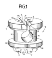
- the inner part 10 of a strain relief comprises an upper part 11, a winding region 12 and a lower part 13.
- a slot 14 is introduced, which passes centrally over the entire diameter of the circular upper part 11.
- the slot 14 merges into a cylindrical bore 15 which passes through the winding portion 12, wherein slot 14 and bore 15 are parallel to each other.
- recesses 16 for a tool such as a cross-slotted screwdriver, are provided in the region of the slot.
- the upper part 11 at the slot 14 bevels 17.
- On the underside 18 of the lower part 13 locking lugs 19 are arranged, between which latching receptacles 20 form.
- the winding region 12 can also be conical to the center of the lateral surface, so that in the middle of the diameter is smaller than the top and bottom.
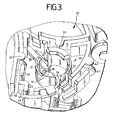
- the outer part 30 is an integral part of a glass fiber connection module 40.
- the fiber optic connection module 40 has different fiber guides 41 and hold-down 42, which will not be explained in detail here.
- the strain relief can also be designed as a completely separate component.
- the outer part 30 has walls 31 which form almost a cylinder jacket, which almost refers to that this cylinder jacket has cutouts 32.
- two elements 33 are arranged, which protrude beyond the inner part 10 in the inserted state (see Fig. 4 ).
- the outer part 30 has a fixing means 34 in the form of a resilient web, which protrudes through the one cutout 32 into the interior of the outer part 30.
- the height of the fixing means 34 is selected such that in the inserted state of the inner part 10, the fixing means 34 presses against the winding region 12 of the inner part 10.
- the outer part 30 has a latching arm 35, which projects into the outer part 30 via a cutout 32 in the region of the latching lugs 19 and latching receivers 20, wherein the front part forms a latching lug 36 which corresponds to the latching receptacles 20.
- the surfaces 43 and 44 or 45 and 46 form the stop for the cable. Behind the surfaces 43, 44 and 45, 46 then cable is performed without a jacket, the thicker cable sheath strikes the surfaces 43-46.
- Fig. 4 is the composite strain relief 50, consisting of inner part 10 and outer part 30, shown.
- the slot 14 is flush with the cutouts 32.
- the Kevlar fibers can then be inserted through the slot 14 in the cylindrical bore 15.
- the fixing element 34 presses the fibers against the winding region 12.
- the inner part 10 preferably performs at least one complete revolution. It should be noted that in this embodiment, the length of the wound fibers must be provided as a reserve length previously, otherwise the cable would be drawn in by the rotation.
- FIG. 5 an alternative embodiment for the inner part 10 is shown, wherein for like parts the same reference numerals as for the embodiment according to Fig. 1 and 2 be used.
- the locking lugs 19 and the locking receptacles 20 are not arranged on the underside 18 of the lower part 13, but on the circumference of the upper part 11.
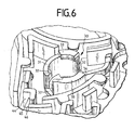
- the outer part 30 is adapted, which in Fig. 6 is shown, again like parts are provided with the same reference numerals.
- the latching arm 35 is omitted and a latching lug 37 is arranged on a wall 31, which then engages in the latching receptacle 20 on the upper part 11.
- the completely assembled strain relief 50 is shown.
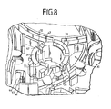
- Fig. 8 is an alternative embodiment for the outer part 30 according to Fig. 6 represented, wherein like elements are provided with the same reference numerals.
- hold-down 47 are arranged, which are chamfered inwardly toward the cutout 32.
- the bevels facilitate the introduction of the Kevlar fibers, the narrow spacing between the hold-downs 47 below the slopes preventing the Kevlar fibers from slipping up so that they can not get caught in the locking lugs of the inner part 10. Accordingly, the fixing agent 34 can be dispensed with.
- FIG. 9 an embodiment of a strain relief 50 with rotational and translational movement of the inner part 10 to the outer part 30 is shown.
- the inner part 10 is essentially as in Fig. 5 formed, wherein the recesses 16 serve to receive a slot screwdriver.
- the arrow R indicates the direction of rotation of the inner part 10.
- the outer part 30 is formed trough-shaped, so that between the walls 31 forms a recess in which the inner part 10 is located.
- the outer part 30 thus has a substantially U-shaped cross-section.
- locking teeth 48 are arranged on the inner sides of the left wall 31 arranged.
- a slot or cutout 32 is shown through which Kevlar fibers 49 can be inserted.
- the Kevlar fibers 49 are then inserted through the cutout 32 and the slot 14 of the inner part 10. If the inner part 10 is then rotated in the direction R, then it rolls with its latching lugs 19 or latching receptacles 20 against the latching teeth 48 of the outer part 30. This rolling movement leads to a translational movement with the translation direction T. The translational movement compensates for the shortening of the Kevlar fibers due to the winding movement around the inner part, so that no reserve length must be provided.
- the end position of the inner part 10 is shown in dashed lines. In the Fig. 9 the ratchet teeth 48 are formed asymmetrically to prevent sliding back of the inner part 10.
- the upper edge of the locking teeth 48 is steeper (almost 90 °) hired as the lower edge.
- other means for securing the inner part 10 may be provided which prevent an automatic turning back.
- means may be provided which correspond to the elements 33 (see eg Fig. 8 ) prevent a lifting movement of the inner part 10. In the present case, this is an aperture 51 at least partially covering the recess of the outer part 30.
Landscapes
- Physics & Mathematics (AREA)
- General Physics & Mathematics (AREA)
- Optics & Photonics (AREA)
- Light Guides In General And Applications Therefor (AREA)
- Moulding By Coating Moulds (AREA)
Description
- Die Erfindung betrifft eine Zugentlastung für Kabel, insbesondere von Glasfaserkabeln mit Kevlar-Fasern.
- Insbesondere bei Glasfaserkabeln mit Kevlar-Fasern (Aramid-Fasern) als mechanische Schutzelemente stellt sich das Problem, das Kabel mechanisch zu befestigen. Hierzu werden beispielsweise Kabelbinder benutzt oder die Kevlarfasern werden gesondert geklemmt.
- Aus der
GB 2 042 817 A - Der Erfindung liegt das technische Problem zugrunde, eine verbesserte Zugentlastung für Kabel, insbesondere für Glasfaserkabel mit Kevlar-Fasern, zu schaffen.
- Die Lösung des technischen Problems ergibt sich durch den Gegenstand mit den Merkmalen des Anspruchs 1. Weitere vorteilhafte Ausgestaltungen der Erfindung ergeben sich aus den Unteransprüchen.
- Hierzu umfasst die Zugentlastung für Kabel, insbesondere für Kevlar-Fasern von Glasfaserkabeln, ein äußeres Teil und ein inneres Teil, wobei das innere Teil eine Aufnahme zum Einlegen der Kevlar-Fasern und einen Wickelbereich aufweist, wobei das innere Teil zu dem äußeren Teil verdrehbar ausgebildet ist. Verdrehbar bedeutet hier allgemein, dass inneres und äußeres Teil relativ zueinander verdrehbar sind, wobei vorzugsweise das äußere Teil fest ist. Hierdurch wird das Kabel einfach und sicher festgehalten. Das Kabel benötigt einen Anschlag, so dass Zug auf die Kevlar-Fasern durch die Wicklung gebracht wird und die Kevlar-Fasern gespannt sind, wodurch die Zugentlastung entsteht. Die Ader oder Faser können beliebiger Natur sein, wobei die Zugentlastung von Kevlar-Fasergeflechten ein bevorzugtes Anwendungsgebiet ist. Prinzipiell kann die Zugentlastung beispielsweise auch für Schirmgeflechte von elektrischen Kabeln verwendet werden.
- Dabei wird die Aufnahme durch einen Schlitz im Oberteil des inneren Teils gebildet, der in eine vorzugsweise zylindrische Bohrung übergeht. Die zylindrische Bohrung bewirkt dabei, dass die eingelegte Faser nicht so einfach wieder aus der Aufnahme herausgleiten kann. Das äußere Teil ist im Bereich des Schlitzes bzw. der Bohrung ebenfalls mit einem Schlitz bzw. Freischnitt ausgebildet, so dass die Fasern waagerecht einlegbar sind. Vorzugsweise sind an den Schlitzen bzw. Freischnitten des äußeren Teils Niederhalter angeordnet, die nach innen abgeschrägt sind. Die Niederhalter halten die Kevlar-Fasern unten, so,dass sich diese nicht an vorstehenden Teilen verfahren können, insbesondere an den noch später erläuterten Rastmitteln.
- In einer weiteren bevorzugten Ausführungsform weist das äußere Teil mindestens ein Fixiermittel auf, das das Kabel oder einen Teil des Kabels, insbesondere die Kevlar-Fasern, gegen den Wickelbereich drückt. Hierdurch wird ein Zurückdrehen der aufgewickelten Kevlar-Fasern verhindert und gewährleistet, dass die Fasern strammer aufgewickelt werden und damit die erforderliche Selbsthemmung erreicht wird. Das Fixiermittel kann einstückig mit dem äußeren Teil ausgebildet sein oder als separates Bauteil ausgebildet sein. Der Wickelbereich ist vorzugsweise zur Mitte der Mantelfläche konisch ausgebildet.
- In einer weiteren bevorzugten Ausführungsform sind das innere Teil und das äußere Teil mit zueinander passenden Rastmitteln ausgebildet, wobei die Anzahl der Rastmittel des inneren Teils unterschiedlich sein kann zu der Anzahl der Rastmittel des äußeren Teils. So kann beispielsweise das äußere Teil eine Rastnase aufweisen und das innere Teil eine Vielzahl von Rastaufnahmen für die Rastnase des äußeren Teils aufweisen oder umgekehrt.
- In einer weiteren bevorzugten Ausführungsform sind die Rastmittel des inneren Teils am Umfang des Oberteils oder an der Unterseite eines Unterteils des inneren Teils angeordnet.
- In einer weiteren bevorzugten Ausführungsform umfasst das äußere Teil mindestens ein Element, das über das Oberteil des inneren Teils hinausragt und so ein herausrutschen verhindert.
- Weiter vorzugsweise ist das Oberteil des inneren Teils mit Ausnehmungen für ein Werkzeug ausgebildet.
- In einer weiteren bevorzugten Ausführungsform ist das innere Teil zusätzlich translatorisch zu dem äußeren Teil ausgebildet. Dabei kompensiert die translatorische Bewegung des inneren Teils die Wickellänge der Faser, so dass keine Reservelänge vor dem Wickelvorgang vorgehalten werden muss. Die Bewegung kann dabei beispielsweise über Zahnräder bzw. Rastzähne erfolgen, wobei das äußere Teil beispielsweise im Querschnitt U-förmig ausgebildet ist. Durch die Drehung bewegt sich dann das innere Teil zusätzlich in das äußere Teil hinein.
- Die Erfindung wird nachfolgend anhand eines bevorzugten Ausführungsbeispieles näher erläutert. Die Fig. zeigen:
- Fig. 1
- eine perspektivische Vorderansicht eines inneren Teils einer Zugentlastung,
- Fig. 2
- eine perspektivische Unteransicht des inneren Teils,
- Fig. 3
- eine perspektivische Draufsicht auf ein äußeres Teil einer Zugentlastung als Bestandteil eines Glasfaseranschlussmoduls,
- Fig. 4
- eine perspektivische Draufsicht auf die zusammengesetzte Zugentlastung,
- Fig. 5
- eine perspektivische Vorderansicht eines inneren Teils in einer alternativen Ausführungsform,
- Fig. 6
- eine perspektivische Draufsicht auf ein äußeres Teil einer Zugentlastung als Bestandteil eines Glasfaseranschlussmoduls für die alternative Ausführungsform,
- Fig. 7
- eine perspektivische Draufsicht auf die zusammengesetzte Zugentlastung der alternativen Ausführungsform,
- Fig. 8
- eine perspektivische Draufsicht auf ein äußeres Teil einer Zugentlastung als Bestandteil eines Glasfaseranschlussmoduls für die alternative Ausführungsform mit Niederhaltern und
- Fig. 9
- eine schematische Draufsicht auf eine Zugentlastung mit zusätzlicher translatorischer Bewegung zwischen dem inneren und äußeren Teil.
- In den
Fig. 1 und2 ist das innere Teil 10 einer Zugentlastung dargestellt. Das innere Teil 10 umfasst ein Oberteil 11, einen Wickelbereich 12 und ein Unterteil 13. In das Oberteil 11 ist ein Schlitz 14 eingebracht, der mittig über den gesamten Durchmesser des kreisrunden Oberteils 11 geht. Der Schlitz 14 geht in eine zylindrische Bohrung 15 über, die durch den Wickelbereich 12 geht, wobei Schlitz 14 und Bohrung 15 zueinander parallel sind. In dem Oberteil 11 sind im Bereich des Schlitzes 14 Ausnehmungen 16 für ein Werkzeug, beispielsweise einen Kreuz-Schlitz-Schraubendreher, vorgesehen. Zum erleichterten Einführen der Fasern weist das Oberteil 11 am Schlitz 14 Schrägen 17 auf. An der Unterseite 18 des Unterteils 13 sind Rastnasen 19 angeordnet, zwischen denen sich Rastaufnahmen 20 bilden. - Der Wickelbereich 12 kann dabei auch zur Mitte der Mantelfläche konisch verlaufen, so dass mittig der Durchmesser kleiner als oben und unten ist.
- In der
Fig. 3 ist ein äußerer Teil 30 der Zugentlastung dargestellt, wobei das äußere Teil 30 integraler Bestandteil eines Glasfaseranschlussmoduls 40 ist. Das Glasfaseranschlussmodul 40 weist dabei verschiedene Faserführungen 41 und Niederhalter 42 auf, die hier jedoch nicht näher erläutert werden sollen. Dabei sei angemerkt, dass die Zugentlastung auch als vollständig separates Bauteil ausgebildet sein kann. Das äußere Teil 30 weist Wände 31 auf, die nahezu einen Zylindermantel bilden, wobei sich nahezu darauf bezieht, dass dieser Zylindermantel Freischnitte 32 aufweist. Auf der Oberseite der Wände 31 sind zwei Elemente 33 angeordnet, die das innere Teil 10 im eingesetzten Zustand überragen (sieheFig. 4 ). Weiter weist das äußere Teil 30 ein Fixiermittel 34 in Form eines federnden Steges auf, das durch den einen Freischnitt 32 in das Innere des äußeren Teils 30 hineinragt. Die Höhe des Fixiermittels 34 ist derart gewählt, dass im eingesetzten Zustand des inneren Teils 10 das Fixiermittel 34 gegen den Wickelbereich 12 des inneren Teils 10 drückt. Weiter weist das äußere Teil 30 einen Rastarm 35 auf, der über einen Freischnitt 32 im Bereich der Rastnasen 19 bzw. Rastaufnahmen 20 in das äußere Teil 30 hineinragt, wobei der vordere Teil eine Rastnase 36 bildet, die zu den Rastaufnahmen 20 korrespondiert. Je nach dem, von wo das Kabel eingeführt wird, bilden die Flächen 43 und 44 bzw. 45 und 46 den Anschlag für das Kabel. Hinter den Flächen 43, 44 bzw. 45, 46 wird dann Kabel ohne Mantel geführt, wobei der dickere Kabelmantel an den Flächen 43-46 anschlägt. - In der
Fig. 4 ist die zusammengesetzte Zugentlastung 50, bestehend aus innerem Teil 10 und äußerem Teil 30, dargestellt. In der Grundposition, wie inFig. 4 dargestellt, liegt der Schlitz 14 fluchtend zu den Freischnitten 32. Die Kevlar-Fasern können dann durch den Schlitz 14 in die zylindrische Bohrung 15 eingelegt werden. Durch Drehung des inneren Teils 10 mittels eines Werkzeugs werden die Fasern auf den Wickelbereich 12 aufgewickelt, wobei die Rastnase 36 nacheinander in die Rastaufnahmen 20 des inneren Teils 10 einrastet und so ein Zurückdrehen verhindert. Das Fixierelement 34 presst dabei die Fasern gegen den Wickelbereich 12. Vorzugsweise führt das innere Teil 10 mindestens eine vollständige Umdrehungen aus. Dabei sei angemerkt, dass bei dieser Ausführungsform die Länge der aufgewickelten Fasern als Reservelänge zuvor bereitgestellt werden muss, da ansonsten durch die Drehung auch das Kabel mit hineingezogen werden würde. - In der
Fig. 5 ist ein alternatives Ausführungsbeispiel für das innere Teil 10 dargestellt, wobei für gleiche Teile gleiche Bezugszeichen wie für die Ausführungsform gemäßFig. 1 und2 verwendet werden. Der einzige Unterschied ist, dass die Rastnasen 19 und die Rastaufnahmen 20 nicht an der Unterseite 18 des Unterteils 13 angeordnet sind, sondern am Umfang des Oberteils 11. Entsprechend ist das äußere Teil 30 angepasst, was inFig. 6 dargestellt ist, wobei wieder gleiche Teile mit gleichen Bezugszeichen versehen sind. Der Unterschied ist, dass der Rastarm 35 entfällt und eine Rastnase 37 an einer Wand 31 angeordnet ist, die dann in die Rastaufnahme 20 am Oberteil 11 eingreift. In derFig. 7 ist schließlich die komplett zusammengesetzte Zugentlastung 50 dargestellt. - In der
Fig. 8 ist eine alternative Ausführungsform für das äußere Teil 30 gemäßFig. 6 dargestellt, wobei gleiche Elemente mit gleichen Bezugszeichen versehen sind. Im Unterschied zuFig. 6 sind benachbart links und rechts von den Freischnitten 32 Niederhalter 47 angeordnet, die nach innen zum Freischnitt 32 hin abgeschrägt ausgebildet sind. Durch die Schrägen wird das Einführen der Kevlar-Fasern erleichtert, wobei der enge Abstand zwischen den Niederhaltern 47 unterhalb der Schrägen ein Hochrutschen der Kevlar-Fasern verhindert, so dass diese sich nicht in den Rastnasen des inneren Teils 10 verfangen können. Entsprechend kann auf das Fixiermittel 34 verzichtet werden. - In der
Fig. 9 ist eine Ausführungsform einer Zugentlastung 50 mit rotatorischer und translatorischer Bewegung des inneren Teils 10 zum äußeren Teil 30 dargestellt. Das innere Teil 10 ist im Wesentlichen wie inFig. 5 dargestellt ausgebildet, wobei die Ausnehmungen 16 zur Aufnahme eines Schlitz-Schraubendrehers dienen. Der Pfeil R deutet die Rotationsrichtung des inneren Teils 10 an. Das äußere Teil 30 ist wannenförmig ausgebildet, so dass sich zwischen den Wänden 31 eine Vertiefung bildet, in der das innere Teil 10 sich befindet. Das äußere Teil 30 weist also einen im Wesentlichen U-förmgien Querschnitt auf. An den Innenseiten der linken Wand 31 sind Rastzähne 48 angeordnet. Im oberen Bereich der linken Wand 31 ist ein Schlitz bzw. Freischnitt 32 dargestellt, durch den Kevlar-Fasern 49 eingelegt werden können. Die Kevlar-Fasern 49 werden dann durch den Freischnitt 32 und den Schlitz 14 des inneren Teils 10 eingelegt. Wird dann das innere Teil 10 in Richtung R gedreht, so rollt dieses mit seinen Rastnasen 19 bzw. Rastaufnahmen 20 an den Rastzähnen 48 des äußeren Teils 30 ab. Diese Abrollbewegung führt zu einer Translationsbewegung mit der Translationsrichtung T. Die Translationsbewegung gleicht dabei die Verkürzung der Kevlar-Fasern aufgrund der Wickelbewegung um das innere Teil aus, so dass keine Reservelänge vorgehalten werden muss. Die Endstellung des inneren Teils 10 ist dabei gestrichelt dargestellt. In derFig. 9 sind die Rastzähne 48 unsymmetrisch ausgebildet, um ein Zurückgleiten des inneren Teils 10 zu verhindern. Dabei ist die obere Flanke der Rastzähne 48 steiler (nahezu 90°) angestellt als die untere Flanke. Alternativ können auch weitere Mittel zum Sichern des inneren Teils 10 vorgesehen sein, die ein selbsttätiges Zurückdrehen verhindern. Weiter können Mittel vorgesehen sein, die entsprechend den Elementen 33 (siehe z.B.Fig. 8 ) eine Hubbewegung des inneren Teils 10 verhindern. Dies ist vorliegend eine mindestens teilweise die Vertiefung des äußeren Teils 30 überdeckende Blende 51. -
- 10
- inneres Teil
- 11
- Oberteil
- 12
- Wickelbereich
- 13
- Unterteil
- 14
- Schlitz
- 15
- Bohrung
- 16
- Ausnehmungen
- 17
- Schrägen
- 18
- Unterseite
- 19
- Rastnasen
- 20
- Rastaufnahmen
- 30
- äußeres Teil
- 31
- Wände
- 32
- Freischnitte
- 33
- Elemente
- 34
- Fixiermittel
- 35
- Rastarm
- 36
- Rastnase
- 37
- Rastnase
- 40
- Glasfaseranschlussmodul
- 41
- Faserführungen
- 42
- Niederhalter
- 43
- Fläche
- 44
- Fläche
- 45
- Fläche
- 46
- Fläche
- 47
- Niederhalter
- 48
- Rastzähne
- 49
- Kevlar-Fasern
- 50
- Zugentlastung
- 51
- Blende
- R
- Rotationsrichtung
- T
- Translationsrichtung
Claims (8)
- Zugentlastung (50) für Kabel, insbesondere für Glasfaserkabel mit Kevlar-Fasern, wobei die Zugentlastung (50) mindestens zweiteilig ausgebildet ist und ein äußeres Teil (30) und ein inneres Teil (10) aufweist, wobei das innere Teil (10) zu dem äußeren Teil (30) verdrehbar ausgebildet und einen Wickelbereich (12) aufweist, wobei die Zugentlastung (50) einen Anschlag (43, 44; 45, 46) für das Kabel aufweist, wobei das innere Teil (10) eine Aufnahme zum Einlegen mindestens eines Teils des Kabels, insbesondere der Kevlar-Fasern aufweist, wobei durch eine Drehung des inneren Teils (10) zum äußeren Teil (30) in der Aufnahme eingelegte Teil des Kabels um den Wickelbereich (12) aufwickelbar sind,
dadurch gekennzeichnet, dass
die Aufnahme durch einen Schlitz (14) im Oberteil (11) des inneren Teils (10) gebildet wird, der in eine Bohrung (15) übergeht und das äußere Teil (30) mit mindestens einem Schlitz bzw. Freischnitt (32) ausgebildet ist, sodass die Fasern waagerecht einlegbar sind. - Zugentlastung nach Anspruch 1, dadurch gekennzeichnet, dass an dem Schlitz bzw. Freischnitt (32) Niederhalter (47) angeordnet sind.
- Zugentlastung nach einem der vorangegangenen Ansprüche, dadurch gekennzeichnet, dass das äußere Teil (30) mindestens ein Fixiermittel (34) aufweist, das das Kabel oder einen Teil des Kabels gegen den Wickelbereich (12) drückt.
- Zugentlastung nach einem der vorangegangenen Ansprüche, dadurch gekennzeichnet, dass das innere Teil (10) und das äußere Teil (30) mit zueinander passenden Rastmitteln (19, 20; 36, 37) ausgebildet sind.
- zugentlastung nach Anspruch 4, dadurch gekennzeichnet, dass die Rastmittel (19, 20) des inneren Teils (10) am Umfang des Oberteils (11) oder an der Unterseite (18) des inneren Teils (10) angeordnet sind.
- Zugentlastung nach einem der vorangegangenen Ansprüche, dadurch gekennzeichnet, dass das äußere Teil (30) Elemente (33) umfasst, die über das Oberteil (11) des inneren Teils (10) ragen.
- Zugentlastung nach einem der vorangegangenen Ansprüche, dadurch gekennzeichnet, dass das Oberteil (11) des inneren Teils (10) mit Ausnehmungen (16) für ein Werkzeug ausgebildet ist.
- Zugentlastung nach einem der vorangegangenen Ansprüche, dadurch gekennzeichnet, dass das innere Teil (10) zusätzlich translatorisch beweglich zu dem äußeren Teil (30) ausgebildet ist.
Applications Claiming Priority (2)
| Application Number | Priority Date | Filing Date | Title |
|---|---|---|---|
| DE102008027380A DE102008027380A1 (de) | 2008-06-09 | 2008-06-09 | Zugentlastung |
| PCT/EP2009/003553 WO2009149813A1 (de) | 2008-06-09 | 2009-05-19 | Zugentlastung |
Publications (2)
| Publication Number | Publication Date |
|---|---|
| EP2288949A1 EP2288949A1 (de) | 2011-03-02 |
| EP2288949B1 true EP2288949B1 (de) | 2014-04-16 |
Family
ID=40933994
Family Applications (1)
| Application Number | Title | Priority Date | Filing Date |
|---|---|---|---|
| EP09761376.4A Active EP2288949B1 (de) | 2008-06-09 | 2009-05-19 | Zugentlastung |
Country Status (6)
| Country | Link |
|---|---|
| US (1) | US8208780B2 (de) |
| EP (1) | EP2288949B1 (de) |
| DE (1) | DE102008027380A1 (de) |
| DK (1) | DK2288949T3 (de) |
| ES (1) | ES2477881T3 (de) |
| WO (1) | WO2009149813A1 (de) |
Cited By (2)
| Publication number | Priority date | Publication date | Assignee | Title |
|---|---|---|---|---|
| DE102017124028A1 (de) | 2017-10-16 | 2019-04-18 | Phoenix Contact E-Mobility Gmbh | Kabelbaugruppe mit einer Kühlleitung und Zugentlastung |
| FR3123464A1 (fr) | 2021-05-26 | 2022-12-02 | Nexans | Pion d’arrimage pour câble, en particulier pour câble optique |
Families Citing this family (8)
| Publication number | Priority date | Publication date | Assignee | Title |
|---|---|---|---|---|
| US9110266B2 (en) | 2011-07-29 | 2015-08-18 | Corning Cable Systems Llc | Fiber optic cables seal and/or strain relief members, and related assemblies and methods |
| EP2570832B1 (de) * | 2011-09-13 | 2016-08-31 | CCS Technology, Inc. | Zugentlastungsvorrichtung für Kabel und faseroptische Verteilungsvorrichtung |
| EP2725396B1 (de) | 2012-10-26 | 2016-09-14 | CCS Technology, Inc. | Zugentlastungsvorrichtung für Kabel und faseroptische Verteilungsvorrichtung |
| US9488793B2 (en) | 2013-09-10 | 2016-11-08 | Corning Optical Communications LLC | Combined optical fiber and power cable |
| DE102013112703A1 (de) * | 2013-11-18 | 2015-05-21 | Reichle & De-Massari Ag | Kabelbefestigungsvorrichtung |
| DE202015106837U1 (de) | 2015-12-16 | 2016-01-11 | ZweiCom GmbH | Glasfaseranschlussdose |
| DE202015106838U1 (de) | 2015-12-16 | 2016-01-12 | ZweiCom GmbH | Kabelzugabfangelement für Glasfaserkabel |
| DE202016102706U1 (de) | 2016-05-20 | 2016-07-01 | ZweiCom GmbH | Kabelzugabfangelement |
Family Cites Families (8)
| Publication number | Priority date | Publication date | Assignee | Title |
|---|---|---|---|---|
| GB2042817A (en) | 1979-02-27 | 1980-09-24 | Cannon Electric Great Britain | Strain relief device for terminating a cable |
| GB2222698B (en) * | 1988-09-13 | 1992-11-04 | British Telecomm | Cable terminator |
| DE9302960U1 (de) * | 1993-03-01 | 1993-04-22 | Diamond S.A., Losone, Locarno | Vorrichtung zum reflexionsarmen Abschließen des freien Endes eines Lichtwellenleiters |
| US6263143B1 (en) * | 1998-10-15 | 2001-07-17 | Lucent Technologies Inc. | Package housing for laser module wound on a spool |
| MXPA03010718A (es) * | 2001-05-25 | 2005-03-07 | Preformed Line Products Co | Recinto y ensamble de cable de fibra optica. |
| US6640041B2 (en) * | 2001-11-20 | 2003-10-28 | Toyokuni Electric Cable Co., Ltd. | Device for winding optical fiber cable |
| US7315681B2 (en) * | 2004-08-09 | 2008-01-01 | Anthony Kewitsch | Fiber optic rotary coupling and devices |
| US7284994B2 (en) * | 2005-06-21 | 2007-10-23 | Adc Telecommunications, Inc. | Grounding lug for armored cable and method |
-
2008
- 2008-06-09 DE DE102008027380A patent/DE102008027380A1/de not_active Withdrawn
-
2009
- 2009-05-19 WO PCT/EP2009/003553 patent/WO2009149813A1/de not_active Ceased
- 2009-05-19 DK DK09761376.4T patent/DK2288949T3/da active
- 2009-05-19 ES ES09761376.4T patent/ES2477881T3/es active Active
- 2009-05-19 EP EP09761376.4A patent/EP2288949B1/de active Active
- 2009-06-08 US US12/479,937 patent/US8208780B2/en not_active Expired - Fee Related
Cited By (3)
| Publication number | Priority date | Publication date | Assignee | Title |
|---|---|---|---|---|
| DE102017124028A1 (de) | 2017-10-16 | 2019-04-18 | Phoenix Contact E-Mobility Gmbh | Kabelbaugruppe mit einer Kühlleitung und Zugentlastung |
| FR3123464A1 (fr) | 2021-05-26 | 2022-12-02 | Nexans | Pion d’arrimage pour câble, en particulier pour câble optique |
| BE1029684A1 (fr) | 2021-05-26 | 2023-03-08 | Nexans | Pion d'arrimage pour câble, en particulier pour câble optique |
Also Published As
| Publication number | Publication date |
|---|---|
| US8208780B2 (en) | 2012-06-26 |
| DE102008027380A1 (de) | 2009-12-10 |
| WO2009149813A1 (de) | 2009-12-17 |
| DK2288949T3 (da) | 2014-07-14 |
| EP2288949A1 (de) | 2011-03-02 |
| ES2477881T3 (es) | 2014-07-18 |
| US20090304343A1 (en) | 2009-12-10 |
Similar Documents
| Publication | Publication Date | Title |
|---|---|---|
| EP2288949A1 (de) | Zugentlastung | |
| EP1860473B1 (de) | Optischer Stecker mit einem in seinem Trägerteil einrastbaren und längsverschiebaren Halteteil | |
| EP2924811B1 (de) | Elektrischer Steckverbinder | |
| DE202008014168U1 (de) | Steckverbindung mit einem Stecker- und einem Buchsenteil und diese aufnehmenden Adaptergehäusen | |
| DE102007010853B4 (de) | Verteilereinrichtung für Lichtwellenleiter | |
| DE10338848A1 (de) | Abfangvorrichtung für optische Kabel, Kabelmuffe mit einer solchen Abfangvorrichtung und Verfahren zur Bereitstellung einer Abfangung für optische Kabel unter Verwendung einer solchen Abfangvorrichtung | |
| DE202008004596U1 (de) | Markierungsvorrichtung | |
| EP2380053A1 (de) | Micro-distribution-kabel für die optische nachrichtentechnik und verfahren zur herstellung eines micro-distribution-kabels | |
| EP2245492B1 (de) | Kabelgrommet | |
| DE102009012335B4 (de) | Zugentlastungsvorrichtung | |
| DE29505242U1 (de) | Verbindungsteil für mehradrige Feldbuskabel | |
| AT524087A1 (de) | Steckverbinderteil für eine optische und/oder elektrische Steckverbindung | |
| WO2008104281A1 (de) | Konsole für eine verteilereinrichtung für lichtwellenleiter-kabel | |
| WO2013050202A1 (de) | Kabelzugentlastung für kabel, insbesondere fiberoptische kabel | |
| WO2012095089A2 (de) | Vorrichtung zur fixierung eines kabels an einen kabelabgangsstutzen | |
| WO2008104280A1 (de) | Trägersytem für eine verteileinrichtung für lichtwellenleiter | |
| DE10008613C2 (de) | Übergangsstück | |
| DE102006046181B4 (de) | Zugentlastungsvorrichtung für ein Glasfaserkabel | |
| DE102011120936A1 (de) | Modulare Kabelhalterungsvorrichtung | |
| EP1209768B1 (de) | Kabelanschluss- oder -verbindungseinrichtung | |
| DE202010009387U1 (de) | Vorrichtung zur Handhabung von Lichtwellenleitern | |
| DE202010007778U1 (de) | Vorrichtung zur Handhabung von Datenleitern | |
| DE102012010816B4 (de) | Kabelabschlusseinrichtung und Verfahren | |
| WO2008104284A1 (de) | Trägersystem zur befestigung von einrichtungen der telekommunikations- und datentechnik | |
| EP3072196B1 (de) | Kabelbefestigungsvorrichtung |
Legal Events
| Date | Code | Title | Description |
|---|---|---|---|
| PUAI | Public reference made under article 153(3) epc to a published international application that has entered the european phase |
Free format text: ORIGINAL CODE: 0009012 |
|
| 17P | Request for examination filed |
Effective date: 20110110 |
|
| AK | Designated contracting states |
Kind code of ref document: A1 Designated state(s): AT BE BG CH CY CZ DE DK EE ES FI FR GB GR HR HU IE IS IT LI LT LU LV MC MK MT NL NO PL PT RO SE SI SK TR |
|
| AX | Request for extension of the european patent |
Extension state: AL BA RS |
|
| RIN1 | Information on inventor provided before grant (corrected) |
Inventor name: KOPF, PIA Inventor name: HETZER, ULRICH |
|
| DAX | Request for extension of the european patent (deleted) | ||
| 17Q | First examination report despatched |
Effective date: 20120814 |
|
| RAP1 | Party data changed (applicant data changed or rights of an application transferred) |
Owner name: TYCO ELECTRONICS SERVICES GMBH |
|
| GRAP | Despatch of communication of intention to grant a patent |
Free format text: ORIGINAL CODE: EPIDOSNIGR1 |
|
| INTG | Intention to grant announced |
Effective date: 20131107 |
|
| GRAS | Grant fee paid |
Free format text: ORIGINAL CODE: EPIDOSNIGR3 |
|
| GRAA | (expected) grant |
Free format text: ORIGINAL CODE: 0009210 |
|
| AK | Designated contracting states |
Kind code of ref document: B1 Designated state(s): AT BE BG CH CY CZ DE DK EE ES FI FR GB GR HR HU IE IS IT LI LT LU LV MC MK MT NL NO PL PT RO SE SI SK TR |
|
| REG | Reference to a national code |
Ref country code: GB Ref legal event code: FG4D Free format text: NOT ENGLISH |
|
| REG | Reference to a national code |
Ref country code: CH Ref legal event code: EP |
|
| REG | Reference to a national code |
Ref country code: AT Ref legal event code: REF Ref document number: 662889 Country of ref document: AT Kind code of ref document: T Effective date: 20140515 |
|
| REG | Reference to a national code |
Ref country code: IE Ref legal event code: FG4D Free format text: LANGUAGE OF EP DOCUMENT: GERMAN |
|
| REG | Reference to a national code |
Ref country code: DE Ref legal event code: R096 Ref document number: 502009009198 Country of ref document: DE Effective date: 20140528 |
|
| REG | Reference to a national code |
Ref country code: DK Ref legal event code: T3 Effective date: 20140711 |
|
| REG | Reference to a national code |
Ref country code: ES Ref legal event code: FG2A Ref document number: 2477881 Country of ref document: ES Kind code of ref document: T3 Effective date: 20140718 |
|
| REG | Reference to a national code |
Ref country code: SE Ref legal event code: TRGR |
|
| REG | Reference to a national code |
Ref country code: NL Ref legal event code: VDEP Effective date: 20140416 |
|
| REG | Reference to a national code |
Ref country code: LT Ref legal event code: MG4D |
|
| PG25 | Lapsed in a contracting state [announced via postgrant information from national office to epo] |
Ref country code: LT Free format text: LAPSE BECAUSE OF FAILURE TO SUBMIT A TRANSLATION OF THE DESCRIPTION OR TO PAY THE FEE WITHIN THE PRESCRIBED TIME-LIMIT Effective date: 20140416 Ref country code: CY Free format text: LAPSE BECAUSE OF FAILURE TO SUBMIT A TRANSLATION OF THE DESCRIPTION OR TO PAY THE FEE WITHIN THE PRESCRIBED TIME-LIMIT Effective date: 20140416 Ref country code: IS Free format text: LAPSE BECAUSE OF FAILURE TO SUBMIT A TRANSLATION OF THE DESCRIPTION OR TO PAY THE FEE WITHIN THE PRESCRIBED TIME-LIMIT Effective date: 20140816 Ref country code: FI Free format text: LAPSE BECAUSE OF FAILURE TO SUBMIT A TRANSLATION OF THE DESCRIPTION OR TO PAY THE FEE WITHIN THE PRESCRIBED TIME-LIMIT Effective date: 20140416 Ref country code: NL Free format text: LAPSE BECAUSE OF FAILURE TO SUBMIT A TRANSLATION OF THE DESCRIPTION OR TO PAY THE FEE WITHIN THE PRESCRIBED TIME-LIMIT Effective date: 20140416 Ref country code: NO Free format text: LAPSE BECAUSE OF FAILURE TO SUBMIT A TRANSLATION OF THE DESCRIPTION OR TO PAY THE FEE WITHIN THE PRESCRIBED TIME-LIMIT Effective date: 20140716 Ref country code: GR Free format text: LAPSE BECAUSE OF FAILURE TO SUBMIT A TRANSLATION OF THE DESCRIPTION OR TO PAY THE FEE WITHIN THE PRESCRIBED TIME-LIMIT Effective date: 20140717 Ref country code: BG Free format text: LAPSE BECAUSE OF FAILURE TO SUBMIT A TRANSLATION OF THE DESCRIPTION OR TO PAY THE FEE WITHIN THE PRESCRIBED TIME-LIMIT Effective date: 20140716 |
|
| PG25 | Lapsed in a contracting state [announced via postgrant information from national office to epo] |
Ref country code: LV Free format text: LAPSE BECAUSE OF FAILURE TO SUBMIT A TRANSLATION OF THE DESCRIPTION OR TO PAY THE FEE WITHIN THE PRESCRIBED TIME-LIMIT Effective date: 20140416 Ref country code: PL Free format text: LAPSE BECAUSE OF FAILURE TO SUBMIT A TRANSLATION OF THE DESCRIPTION OR TO PAY THE FEE WITHIN THE PRESCRIBED TIME-LIMIT Effective date: 20140416 Ref country code: HR Free format text: LAPSE BECAUSE OF FAILURE TO SUBMIT A TRANSLATION OF THE DESCRIPTION OR TO PAY THE FEE WITHIN THE PRESCRIBED TIME-LIMIT Effective date: 20140416 |
|
| PG25 | Lapsed in a contracting state [announced via postgrant information from national office to epo] |
Ref country code: PT Free format text: LAPSE BECAUSE OF FAILURE TO SUBMIT A TRANSLATION OF THE DESCRIPTION OR TO PAY THE FEE WITHIN THE PRESCRIBED TIME-LIMIT Effective date: 20140818 |
|
| REG | Reference to a national code |
Ref country code: CH Ref legal event code: PL |
|
| REG | Reference to a national code |
Ref country code: DE Ref legal event code: R097 Ref document number: 502009009198 Country of ref document: DE |
|
| PG25 | Lapsed in a contracting state [announced via postgrant information from national office to epo] |
Ref country code: CZ Free format text: LAPSE BECAUSE OF FAILURE TO SUBMIT A TRANSLATION OF THE DESCRIPTION OR TO PAY THE FEE WITHIN THE PRESCRIBED TIME-LIMIT Effective date: 20140416 Ref country code: LI Free format text: LAPSE BECAUSE OF NON-PAYMENT OF DUE FEES Effective date: 20140531 Ref country code: CH Free format text: LAPSE BECAUSE OF NON-PAYMENT OF DUE FEES Effective date: 20140531 Ref country code: EE Free format text: LAPSE BECAUSE OF FAILURE TO SUBMIT A TRANSLATION OF THE DESCRIPTION OR TO PAY THE FEE WITHIN THE PRESCRIBED TIME-LIMIT Effective date: 20140416 Ref country code: MC Free format text: LAPSE BECAUSE OF FAILURE TO SUBMIT A TRANSLATION OF THE DESCRIPTION OR TO PAY THE FEE WITHIN THE PRESCRIBED TIME-LIMIT Effective date: 20140416 Ref country code: RO Free format text: LAPSE BECAUSE OF FAILURE TO SUBMIT A TRANSLATION OF THE DESCRIPTION OR TO PAY THE FEE WITHIN THE PRESCRIBED TIME-LIMIT Effective date: 20140416 Ref country code: SK Free format text: LAPSE BECAUSE OF FAILURE TO SUBMIT A TRANSLATION OF THE DESCRIPTION OR TO PAY THE FEE WITHIN THE PRESCRIBED TIME-LIMIT Effective date: 20140416 |
|
| PLBE | No opposition filed within time limit |
Free format text: ORIGINAL CODE: 0009261 |
|
| STAA | Information on the status of an ep patent application or granted ep patent |
Free format text: STATUS: NO OPPOSITION FILED WITHIN TIME LIMIT |
|
| REG | Reference to a national code |
Ref country code: IE Ref legal event code: MM4A |
|
| REG | Reference to a national code |
Ref country code: FR Ref legal event code: ST Effective date: 20150130 |
|
| 26N | No opposition filed |
Effective date: 20150119 |
|
| GBPC | Gb: european patent ceased through non-payment of renewal fee |
Effective date: 20140716 |
|
| PG25 | Lapsed in a contracting state [announced via postgrant information from national office to epo] |
Ref country code: IT Free format text: LAPSE BECAUSE OF FAILURE TO SUBMIT A TRANSLATION OF THE DESCRIPTION OR TO PAY THE FEE WITHIN THE PRESCRIBED TIME-LIMIT Effective date: 20140416 |
|
| PG25 | Lapsed in a contracting state [announced via postgrant information from national office to epo] |
Ref country code: IE Free format text: LAPSE BECAUSE OF NON-PAYMENT OF DUE FEES Effective date: 20140519 |
|
| REG | Reference to a national code |
Ref country code: DE Ref legal event code: R097 Ref document number: 502009009198 Country of ref document: DE Effective date: 20150119 |
|
| PG25 | Lapsed in a contracting state [announced via postgrant information from national office to epo] |
Ref country code: GB Free format text: LAPSE BECAUSE OF NON-PAYMENT OF DUE FEES Effective date: 20140716 Ref country code: FR Free format text: LAPSE BECAUSE OF NON-PAYMENT OF DUE FEES Effective date: 20140616 |
|
| REG | Reference to a national code |
Ref country code: AT Ref legal event code: MM01 Ref document number: 662889 Country of ref document: AT Kind code of ref document: T Effective date: 20140519 |
|
| PG25 | Lapsed in a contracting state [announced via postgrant information from national office to epo] |
Ref country code: SI Free format text: LAPSE BECAUSE OF FAILURE TO SUBMIT A TRANSLATION OF THE DESCRIPTION OR TO PAY THE FEE WITHIN THE PRESCRIBED TIME-LIMIT Effective date: 20140416 |
|
| PG25 | Lapsed in a contracting state [announced via postgrant information from national office to epo] |
Ref country code: AT Free format text: LAPSE BECAUSE OF NON-PAYMENT OF DUE FEES Effective date: 20140519 |
|
| PG25 | Lapsed in a contracting state [announced via postgrant information from national office to epo] |
Ref country code: MT Free format text: LAPSE BECAUSE OF FAILURE TO SUBMIT A TRANSLATION OF THE DESCRIPTION OR TO PAY THE FEE WITHIN THE PRESCRIBED TIME-LIMIT Effective date: 20140416 |
|
| PG25 | Lapsed in a contracting state [announced via postgrant information from national office to epo] |
Ref country code: TR Free format text: LAPSE BECAUSE OF FAILURE TO SUBMIT A TRANSLATION OF THE DESCRIPTION OR TO PAY THE FEE WITHIN THE PRESCRIBED TIME-LIMIT Effective date: 20140416 Ref country code: HU Free format text: LAPSE BECAUSE OF FAILURE TO SUBMIT A TRANSLATION OF THE DESCRIPTION OR TO PAY THE FEE WITHIN THE PRESCRIBED TIME-LIMIT; INVALID AB INITIO Effective date: 20090519 Ref country code: BE Free format text: LAPSE BECAUSE OF FAILURE TO SUBMIT A TRANSLATION OF THE DESCRIPTION OR TO PAY THE FEE WITHIN THE PRESCRIBED TIME-LIMIT Effective date: 20140531 Ref country code: LU Free format text: LAPSE BECAUSE OF NON-PAYMENT OF DUE FEES Effective date: 20140519 |
|
| PG25 | Lapsed in a contracting state [announced via postgrant information from national office to epo] |
Ref country code: MK Free format text: LAPSE BECAUSE OF FAILURE TO SUBMIT A TRANSLATION OF THE DESCRIPTION OR TO PAY THE FEE WITHIN THE PRESCRIBED TIME-LIMIT Effective date: 20140416 |
|
| PGFP | Annual fee paid to national office [announced via postgrant information from national office to epo] |
Ref country code: SE Payment date: 20220527 Year of fee payment: 14 Ref country code: ES Payment date: 20220601 Year of fee payment: 14 Ref country code: DK Payment date: 20220531 Year of fee payment: 14 |
|
| P01 | Opt-out of the competence of the unified patent court (upc) registered |
Effective date: 20230530 |
|
| REG | Reference to a national code |
Ref country code: SE Ref legal event code: EUG Ref country code: DK Ref legal event code: EBP Effective date: 20230531 |
|
| PG25 | Lapsed in a contracting state [announced via postgrant information from national office to epo] |
Ref country code: SE Free format text: LAPSE BECAUSE OF NON-PAYMENT OF DUE FEES Effective date: 20230520 |
|
| PG25 | Lapsed in a contracting state [announced via postgrant information from national office to epo] |
Ref country code: DK Free format text: LAPSE BECAUSE OF NON-PAYMENT OF DUE FEES Effective date: 20230531 |
|
| REG | Reference to a national code |
Ref country code: ES Ref legal event code: FD2A Effective date: 20240701 |
|
| PG25 | Lapsed in a contracting state [announced via postgrant information from national office to epo] |
Ref country code: ES Free format text: LAPSE BECAUSE OF NON-PAYMENT OF DUE FEES Effective date: 20230520 |
|
| PG25 | Lapsed in a contracting state [announced via postgrant information from national office to epo] |
Ref country code: ES Free format text: LAPSE BECAUSE OF NON-PAYMENT OF DUE FEES Effective date: 20230520 |
|
| PGFP | Annual fee paid to national office [announced via postgrant information from national office to epo] |
Ref country code: DE Payment date: 20250529 Year of fee payment: 17 |