EP2288538B1 - Flugzeugsystemträgerelement - Google Patents
Flugzeugsystemträgerelement Download PDFInfo
- Publication number
- EP2288538B1 EP2288538B1 EP09761467A EP09761467A EP2288538B1 EP 2288538 B1 EP2288538 B1 EP 2288538B1 EP 09761467 A EP09761467 A EP 09761467A EP 09761467 A EP09761467 A EP 09761467A EP 2288538 B1 EP2288538 B1 EP 2288538B1
- Authority
- EP
- European Patent Office
- Prior art keywords
- aircraft
- carrier element
- system carrier
- compartment
- duct
- Prior art date
- Legal status (The legal status is an assumption and is not a legal conclusion. Google has not performed a legal analysis and makes no representation as to the accuracy of the status listed.)
- Not-in-force
Links
- 238000004378 air conditioning Methods 0.000 claims abstract description 44
- 239000011810 insulating material Substances 0.000 claims abstract description 3
- 239000006260 foam Substances 0.000 claims description 4
- 230000003746 surface roughness Effects 0.000 claims description 4
- 238000009413 insulation Methods 0.000 description 13
- 239000006261 foam material Substances 0.000 description 7
- QVGXLLKOCUKJST-UHFFFAOYSA-N atomic oxygen Chemical compound [O] QVGXLLKOCUKJST-UHFFFAOYSA-N 0.000 description 6
- 229910052760 oxygen Inorganic materials 0.000 description 6
- 239000001301 oxygen Substances 0.000 description 6
- 239000011248 coating agent Substances 0.000 description 5
- 238000000576 coating method Methods 0.000 description 5
- 239000000463 material Substances 0.000 description 4
- 238000009434 installation Methods 0.000 description 3
- 238000012423 maintenance Methods 0.000 description 3
- 239000004033 plastic Substances 0.000 description 2
- 229920003023 plastic Polymers 0.000 description 2
- 229920007790 polymethacrylimide foam Polymers 0.000 description 2
- 239000004814 polyurethane Substances 0.000 description 2
- 238000007789 sealing Methods 0.000 description 2
- 239000002023 wood Substances 0.000 description 2
- KXGFMDJXCMQABM-UHFFFAOYSA-N 2-methoxy-6-methylphenol Chemical compound [CH]OC1=CC=CC([CH])=C1O KXGFMDJXCMQABM-UHFFFAOYSA-N 0.000 description 1
- 229920005830 Polyurethane Foam Polymers 0.000 description 1
- 239000000853 adhesive Substances 0.000 description 1
- 230000001070 adhesive effect Effects 0.000 description 1
- 230000001143 conditioned effect Effects 0.000 description 1
- 238000010276 construction Methods 0.000 description 1
- 230000007613 environmental effect Effects 0.000 description 1
- 239000011888 foil Substances 0.000 description 1
- 239000011491 glass wool Substances 0.000 description 1
- 238000002955 isolation Methods 0.000 description 1
- 238000004519 manufacturing process Methods 0.000 description 1
- 239000002184 metal Substances 0.000 description 1
- 239000005011 phenolic resin Substances 0.000 description 1
- 229920001568 phenolic resin Polymers 0.000 description 1
- 229920002635 polyurethane Polymers 0.000 description 1
- 230000001681 protective effect Effects 0.000 description 1
- 239000000779 smoke Substances 0.000 description 1
Images


Classifications
-
- B—PERFORMING OPERATIONS; TRANSPORTING
- B64—AIRCRAFT; AVIATION; COSMONAUTICS
- B64C—AEROPLANES; HELICOPTERS
- B64C1/00—Fuselages; Constructional features common to fuselages, wings, stabilising surfaces or the like
- B64C1/06—Frames; Stringers; Longerons ; Fuselage sections
- B64C1/066—Interior liners
-
- B—PERFORMING OPERATIONS; TRANSPORTING
- B64—AIRCRAFT; AVIATION; COSMONAUTICS
- B64C—AEROPLANES; HELICOPTERS
- B64C1/00—Fuselages; Constructional features common to fuselages, wings, stabilising surfaces or the like
- B64C2001/0054—Fuselage structures substantially made from particular materials
- B64C2001/0072—Fuselage structures substantially made from particular materials from composite materials
-
- Y—GENERAL TAGGING OF NEW TECHNOLOGICAL DEVELOPMENTS; GENERAL TAGGING OF CROSS-SECTIONAL TECHNOLOGIES SPANNING OVER SEVERAL SECTIONS OF THE IPC; TECHNICAL SUBJECTS COVERED BY FORMER USPC CROSS-REFERENCE ART COLLECTIONS [XRACs] AND DIGESTS
- Y02—TECHNOLOGIES OR APPLICATIONS FOR MITIGATION OR ADAPTATION AGAINST CLIMATE CHANGE
- Y02T—CLIMATE CHANGE MITIGATION TECHNOLOGIES RELATED TO TRANSPORTATION
- Y02T50/00—Aeronautics or air transport
- Y02T50/40—Weight reduction
Definitions
- the invention relates to a system support element which is intended to be used in an aircraft for the installation of lines required for the supply of an aircraft compartment and as an aircraft compartment insulation.
- inserts on the outer surfaces of the aircraft compartment walls.
- the inserts which are generally made of metal and provided with an internal thread, are arranged individually in corresponding receptacles which are formed in the panels forming the aircraft compartment walls. The inserts may then be used to bolt suitable fasteners for attaching the system leads to the panels forming the aircraft compartment walls with the panels.
- the acoustic insulation of the aircraft compartment is usually carried out with the aid of so-called heavy foils, which are glued to the outer surfaces of the panels forming the aircraft compartment walls prior to assembly of the fastening devices for fastening the system lines to the panels forming the aircraft compartment walls.
- the thermal insulation of the aircraft compartment is finally realized by glass wool packages, which are also mounted in a separate step to the aircraft compartment walls forming panels with the system lines attached thereto.
- a major disadvantage of attaching the system leads by means of inserts is that the positioning of the inserts is usually customer-specific. As a result, customized panels and insert layouts must be generated for each customer. Moreover, the system lines attached to the outer surfaces of the panels forming the aircraft compartment walls are relatively unprotected. Electrical supply lines and oxygen lines must therefore often be laid inside the Compartment and provided with appropriate protective covers, which makes the installation and maintenance of the lines difficult and slow. Finally, the assembly of the acoustic and thermal Isolations of the aircraft compartment in separate steps very time and therefore costly.
- the invention has for its object to provide an aircraft system support member that allows easy and quick installation of required for the supply of an aircraft compartments lines and an aircraft compartment insulation.
- an aircraft system carrier element comprises a base body consisting of a sound and heat insulating material.
- an air-conditioning duct connectable with an aircraft air conditioning system and provided for the supply of an aircraft compartment and a duct for receiving lines intended for the supply of aircraft compartments are formed.
- the aircraft system carrier according to the invention thus not only comprises an integrated air conditioning duct and a duct for receiving the system ducts required for supplying the aircraft compartment, but moreover functions as sound and heat insulation for the aircraft compartment.
- the aircraft system support element according to the invention is preferably attached to an outer surface of an aircraft compartment wall.
- only one air conditioning duct and only one duct can be formed.
- a significant advantage of the system support element according to the invention is that it is no longer necessary to fasten the system lines for supplying the aircraft compartment individually with the aid of individually positionable inserts on a panel forming an aircraft compartment wall.
- the aircraft system carrier element can be preassembled with the lines provided for the supply of the aircraft compartment to form an independently manageable subassembly and only then be fastened to a panel forming an aircraft compartment wall.
- the number of attachment points to be provided on a panel forming an aircraft compartment wall, which may be in the form of inserts or other suitable mounting devices, may therefore be reduced considerably.
- a further advantage of the aircraft system carrier element according to the invention is that a separate acoustic and thermal insulation of the aircraft compartment can be dispensed with by using an aircraft system carrier element according to the invention.
- the system lines accommodated in the duct are well protected against external influences. It is therefore no longer necessary to have sensitive system leads, such as e.g. electrical cables or oxygen lines, to be laid inside the aircraft compartment and provided with separate covers.
- the system carrier element according to the invention consequently makes it possible to considerably simplify the assembly of the acoustic and thermal insulation of the aircraft compartment as well as the assembly of the system lines required for supplying the aircraft compartment.
- the aircraft system carrier element according to the invention can be used, for example, in conjunction with a crew rest compartment. Since a crew rest compartment must be conditioned with the aid of the aircraft air conditioning system and, moreover, a plurality of system ducts, such as e.g. electrical lines and oxygen lines to supply the crew rest compartment is required, the aircraft system support element according to the invention can simplify the assembly of these components in a particularly advantageous manner considerably. Moreover, the system support element according to the invention provides the desired acoustic and thermal insulation of the crew rest compartment. However, the aircraft system carrier element according to the invention can also be used in conjunction with other aircraft compartments, which can be arranged in an upper or an underfloor area of the aircraft, but also in the area of an aircraft passenger cabin.
- the main body of the aircraft system support element according to the invention is designed in several parts and comprises a rear wall, which is provided on an outer surface of an aircraft compartment wall, i. to be secured to an outer surface of a panel forming the aircraft compartment wall or to exterior surfaces of a plurality of panels forming the aircraft compartment wall. Furthermore, the main body of the aircraft system carrier element according to the invention comprises a cable duct cover detachably fastened to the rear wall. A conduit channel cover removably secured to the rear wall allows rapid access to the system conduits received in the conduit, thereby greatly simplifying the maintenance of these conduits.
- the main body of the aircraft system carrier element according to the invention preferably consists of a sound and heat insulating foam.
- the foam material of the main body can be selected depending on the application depending on the required sound and heat insulation properties of the aircraft system carrier element become.
- a foam material suitable for producing the main body of the aircraft system carrier element according to the invention must have a high fire resistance and, in the event of a fire, lead to only slight smoke development.
- the main body of the aircraft system support element according to the invention from a PU (polyurethane), a PF (phenolic resin) or a PMI (polymethacrylimide) foam material or a wood material, such as Baltek ® are manufactured.
- PU polyurethane
- PF phenolic resin
- PMI polymethacrylimide
- a wood material such as Baltek ®
- an existing from a foam material body is characterized by a low weight.
- the main body may comprise a connectable to the rear wall air duct cover.
- both the rear wall and the air conditioning duct cover is provided with corresponding adhesive surfaces, so that the air conditioning duct cover can be glued to the rear wall in a simple and comfortable manner.
- a three-piece designed basic body with a rear wall, a duct cover and an air conditioning duct cover is relatively easy to manufacture.
- the basic body can also be designed in one piece or in two parts.
- a component forming the rear wall and the air-conditioning duct cover of the main body can be made in one piece.
- At least one passage for guiding a line provided for supplying the aircraft compartment is preferably formed from the aircraft system carrier element into the aircraft compartment.
- the Feedthrough is preferably in the region of the formed in the base body duct.
- a suitable sealing element for sealing the bushing may be arranged in the region of the bushing.
- an inner surface of the air conditioning duct preferably has a surface roughness which does not exceed a predetermined value.
- the inner surface of the air conditioning duct can be correspondingly surface-treated or provided with a coating.
- a coating applied to an inner surface of the air conditioning duct may also serve to seal the air conditioning duct, which may be advantageous in particular if the base body consists of a porous foam material.
- a thin-walled, for example made of a plastic material pipe may be integrated into the air conditioning duct.
- a plurality of different system lines can be guided by the line channel formed in the main body of the aircraft system carrier element according to the invention.
- certain lines such as e.g. Laying electrical lines or oxygen lines at a certain distance from other lines.
- a plurality of receptacles is preferably arranged for the attachment of line fasteners, which serve to attach suitable means for attaching the guided through the duct ducts in the duct.
- the receptacles can for example consist of a plastic material and be shaped and dimensioned so that they allow a routing of the guided through the duct ducts at a desired distance from each other.
- the aircraft system carrier element according to the invention is intended for mounting on an outer surface of an aircraft compartment wall.
- Aircraft compartments are usually with the help of appropriate holder on a Aircraft structure attached.
- the holders typically extend from the aircraft compartment walls toward the aircraft structure.
- at least one recess for receiving a holder for fastening the aircraft compartment to the aircraft structure is formed in the main body of the aircraft system carrier element according to the invention.
- the rear wall of the main body may be provided with a recess or a plurality of recesses through which a holder or a plurality of holders for fastening the aircraft compartment to the aircraft structure extends / extend in the state mounted on an aircraft compartment wall of the aircraft system carrier element.
- a component of the basic body lying opposite the rear wall ie the duct cover and / or the air-conditioning duct cover may be provided with a recess or a plurality of recesses for receiving a holder or a plurality of holders for fastening the aircraft compartment to the aircraft structure.
- the aircraft system support element according to the invention may further comprise a side wall, which is connected in the region of the duct with the base body and provided with corresponding passages for guiding the provided for the supply of the aircraft compartment lines in the duct or from the duct.
- the aircraft system carrier element comprises two side walls which close the conduit on both sides.
- the side wall or the side walls may be integrally formed with the base body or as a separate component / separate components.
- a side channel provided with duct provides a particularly good protection of laid in the duct ducts from external influences.
- the size and shape of the aircraft system support member of the invention are preferably matched to the size and shape of an aircraft compartment sidewall to which the aircraft system support member is to be mounted.
- the aircraft system carrier element can extend over a large area over an aircraft compartment side wall.
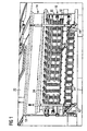
- An aircraft system carrier element 10 shown in the figures comprises a base body 12, which consists of a sound and heat insulating foam, such as PU foam, PF foam or PMI foam or a wood material, such as Baltek ® .
- the main body 12 comprises a rear wall 13, which comprises a half-shell of an air-conditioning duct 14 and a half-shell of a duct 16.
- the rear wall 13 is adhesively bonded to an air-conditioning duct cover 18.
- An inner surface of the air conditioning duct 14 is provided with a coating to ensure that the surface roughness of the indoor air duct surface does not exceed a predetermined value.
- the coating applied to the inner surface of the air-conditioning duct 14 seals the air-conditioning duct 14, which is advantageous in particular when the base body 12 of the aircraft system support element 10 consists of a porous foam material.
- the lines 20 serve, as well as the air conditioning duct 14, the supply of an aircraft compartments 22.
- a plurality of receptacles 24 is disposed in the duct 16.
- the receptacles 24 serve to attach in the figures not shown line fastening means for laying the lines 20 at a desired distance from each other in the duct 16.
- the duct 16 is by means of a detachably secured to the rear wall 13 duct cover 26 (see FIGS. 4 to 6 ) locked.
- the laid in the duct 16 lines 20 are thus well protected from environmental influences. For maintenance purposes, however, the lines 20 are easily accessible through the releasable attachment of the duct cover 26.
- the air conditioning duct 14 and the ducts 20 guided through the duct 16 serve to supply the aircraft compartment 22.
- the air conditioning duct 14 is connected to an air conditioning air inlet opening (not shown in the figures) formed in an aircraft compartment wall.
- the ducts 20 routed through the duct 16 are connected to corresponding consumers arranged in the aircraft compartment 22.
- the lines 20 are led out of the aircraft system carrier element 10 by feedthroughs, not shown in the figures, which are formed in the rear wall 13 of the base 12 in the region of the line channel 16.
- the passages formed in the rear wall 13 of the aircraft system carrier element main body 12 are aligned with corresponding passages in the aircraft compartment wall.
- the aircraft system support member 10 further comprises two side walls 28, 30 which are connected in the region of the duct 16 with the base body 12 and thus close the duct 16 laterally.
- the side walls 28, 30 corresponding passages 32 for guiding the lines 20 in the duct 16 and from the duct 16 are provided.
- the aircraft system carrier element 10 extends over a large area along a wall of the aircraft compartment 22 and thereby ensures optimum sound and heat insulation of the aircraft compartment 22. Therefore, additional acoustic and thermal insulation of the aircraft compartment 22 can be dispensed with.
- the main body 12 of the aircraft system carrier element 10 is provided with recesses 34, 36, 38, 40 corresponding to the mounted on the aircraft compartment wall state of the aircraft system support member 10 holder 42, 44 for attachment of the aircraft compartment 22 record on the aircraft structure.
- First recesses 34, 36 are formed in the rear wall 13 of the main body 12.
- second recesses 38, 40 extend in the duct cover 26 and the air-conditioning duct cover 18, and each include a portion passing through the duct cover 26 completely and a recess formed in the duct cover 26 and the air-conditioning duct cover 18.
Landscapes
- Engineering & Computer Science (AREA)
- Mechanical Engineering (AREA)
- Aviation & Aerospace Engineering (AREA)
- Duct Arrangements (AREA)
- Soundproofing, Sound Blocking, And Sound Damping (AREA)
- Air-Conditioning For Vehicles (AREA)
Description
- Die Erfindung betrifft ein Systemträgerelement, das dazu vorgesehen ist, in einem Flugzeug zur Montage von zur Versorgung eines Flugzeugcompartments erforderlichen Leitungen sowie als Flugzeugcompartmentisolierung eingesetzt zu werden.
- Ein wesentlicher Stand der Technik ist durch
EP1510454 gegeben. - Zur Versorgung eines Flugzeugcompartments, beispielsweise eines Crew Rest Compartments erforderliche Systemleitungen, wie z.B. elektrische Leitungen, Sauerstoffleitungen oder Rohrleitungen der Klimaanlage werden derzeit üblicherweise mit Hilfe sogenannter Inserts an den Außenflächen der Flugzeugcompartmentwände befestigt. Die in der Regel aus Metall bestehenden und mit einem Innengewinde versehenen Inserts werden hierzu einzeln in entsprechenden Aufnahmen angeordnet, die in den die Flugzeugcompartmentwände bildenden Paneelen ausgebildet sind. Die Inserts können dann dazu genutzt werden, geeignete Befestigungsvorrichtungen zur Befestigung der Systemleitungen an den die Flugzeugcompartmentwände bildenden Paneelen mit den Paneelen zu verschrauben.
- Die akustische Isolierung des Flugzeugcompartments erfolgt üblicherweise mit Hilfe sogenannter Schwerfolien, die vor der Montage der Befestigungsvorrichtungen zur Befestigung der Systemleitungen an den die Flugzeugcompartmentwände bildenden Paneelen in einem separaten Arbeitsschritt auf die Außenflächen der die Flugzeugcompartmentwände bildenden Paneele aufgeklebt werden. Die thermische Isolierung des Flugzeugcompartments wird schließlich durch Glaswollpakete realisiert, die ebenfalls in einem separaten Arbeitsschritt an den die Flugzeugcompartmentwände bildenden Paneelen mit den daran befestigten Systemleitungen angebracht werden.
- Ein wesentlicher Nachteil der Befestigung der Systemleitungen mit Hilfe von Inserts besteht darin, dass die Positionierung der Inserts üblicherweise kundenspezifisch erfolgt. Infolge dessen müssen für jeden Kunden individuell gestaltet Paneele und Insertlayouts generiert werden. Darüber hinaus sind die an den Außenflächen der die Flugzeugcompartmentwände bildenden Paneele angebrachten Systemleitungen verhältnismäßig ungeschützt. Elektrische Versorgungsleitungen und Sauerstoffleitungen müssen daher häufig im Inneren des Compartments verlegt und mit entsprechenden Schutzabdeckungen versehen werden, was die Montage und Wartung der Leitungen erschwert und verlangsamt. Schließlich ist die Montage der akustischen und thermischen Isolierungen des Flugzeugcompartments in separaten Arbeitsschritten sehr zeit- und folglich kostenaufwändig.
- Der Erfindung liegt die Aufgabe zugrunde, ein Flugzeugsystemträgerelement bereitzustellen, das eine einfache und schnelle Montage von zur Versorgung eines Flugzeugcompartments erforderlichen Leitungen sowie einer Flugzeugcompartmentisolierung ermöglicht.
- Zur Lösung dieser Aufgabe umfasst ein erfindungsgemäßes Flugzeugsystemträgerelement einen aus einem schall- und wärmeisolierenden Material bestehenden Grundkörper. In dem Grundkörper sind ein mit einer Flugzeugklimaanlage verbindbarer und zur Versorgung eines Flugzeugcompartments vorgesehener Klimakanal sowie ein Leitungskanal zur Aufnahme von zur Versorgung Flugzeugcompartments vorgesehenen Leitungen ausgebildet. Der erfindungsgemäße Flugzeugsystemträger umfasst somit nicht nur einen integrierten Klimakanal sowie einen Leitungskanal zur Aufnahme der zur Versorgung des Flugzeugcompartments erforderlichen Systemleitungen, sondern fungiert überdies als Schall- und Wärmeisolierung für das Flugzeugcompartment. Um eine optimale Schall- und Wärmeisolierung zu erzielen, wird das erfindungsgemäße Flugzeugsystemträgerelement vorzugsweise an einer Außenfläche einer Flugzeugcompartmentwand angebracht. In dem Grundkörper des erfindungsgemäßen Flugzeugsystemträgerelements kann lediglich ein Klimakanal sowie lediglich ein Leitungskanal ausgebildet sein. Alternativ dazu ist es jedoch auch denkbar, in dem Grundkörper mehrere Klimakanäle und/oder mehrere Leitungskanäle vorzusehen. Ferner ist es denkbar, den Klimakanal und/oder den Leitungskanal in voneinander getrennte Abschnitte zu unterteilen.
- Ein wesentlicher Vorteil des erfindungsgemäßen Systemträgerelements besteht darin, dass es nicht länger erforderlich ist, die Systemleitungen zur Versorgung des Flugzeugcompartments einzeln mit Hilfe von individuell zu positionierenden Inserts an einem eine Flugzeugcompartmentwand bildenden Paneel zu befestigen. Stattdessen kann das Flugzeugsystemträgerelement mit den zur Versorgung des Flugzeugcompartments vorgesehenen Leitungen zu einer eigenständig handhabbaren Baugruppe vormontiert und erst anschließend an einem eine Flugzeugcompartmentwand bildenden Paneel befestigt werden. Die Anzahl der an einem eine Flugzeugcompartmentwand bildenden Paneel vorzusehenden Anbindungspunkte, die in Form von Inserts oder anderen geeigneten Montagevorrichtungen gestaltet sein können, kann daher beträchtlich reduziert werden. Darüber hinaus ist es bei der Verwendung eines standardisierten Flugzeugsystemträgerelements lediglich erforderlich, an einem eine Flugzeugcompartmentseitenwand bildenden Paneel zur Befestigung des Flugzeugsystemträgerelements an dem Paneel geeignete Anbindungspunkte an standardisierten Positionen vorzusehen. Dadurch kann die Variantenvielfalt der zur Bildung von Flugzeugcompartmentwänden eingesetzten Paneele beträchtlich reduziert werden.
- Ein weiterer Vorteil des erfindungsgemäßen Flugzeugsystemträgerelements besteht darin, dass durch den Einsatz eines erfindungsgemäßen Flugzeugsystemträgerelements auf eine separate akustische und thermische Isolierung des Flugzeugcompartments verzichtet werden kann. Darüber hinaus sind die in dem Leitungskanal aufgenommenen Systemleitungen gut vor äußeren Einwirkungen geschützt sind. Es ist daher nicht länger erforderlich, empfindliche Systemleitungen, wie z.B. elektrische Leitungen oder Sauerstoffleitungen, im Inneren des Flugzeugcompartments zu verlegen und mit separaten Abdeckungen zu versehen. Durch das erfindungsgemäße Systemträgerelement kann folglich die Montage der akustischen und thermischen Isolierung des Flugzeugcompartments sowie die Montage der zur Versorgung des Flugzeugcompartments erforderlichen Systemleitungen in erheblichem Maße vereinfacht werden.
- Das erfindungsgemäße Flugzeugsystemträgerelement kann beispielsweise im Zusammenhang mit einem Crew Rest Compartment eingesetzt werden. Da ein Crew Rest Compartment mit Hilfe der Flugzeugklimaanlage klimatisiert werden muss und überdies eine Vielzahl von Systemleitungen, wie z.B. elektrische Leitungen und Sauerstoffleitungen zur Versorgung des Crew Rest Compartments erforderlich ist, kann das erfindungsgemäße Flugzeugsystemträgerelement die Montage dieser Komponenten in besonders vorteilhafter Weise beträchtlich vereinfachen. Überdies sorgt das erfindungsgemäße Systemträgerelement für die gewünschte akustische und thermische Isolierung des Crew Rest Compartments. Das erfindungsgemäße Flugzeugsystemträgerelement kann jedoch auch im Zusammenhang mit anderen Flugzeugcompartments eingesetzt werden, die in einem Ober- oder einem Unterflurbereich des Flugzeugs, aber auch im Bereich einer Flugzeugpassagierkabine angeordnet sein können.
- Der Grundkörper des erfindungsgemäßen Flugzeugsystemträgerelements ist mehrteilig ausgebildet und umfasst eine Rückwand, die dazu vorgesehen ist, an einer Außenfläche einer Flugzeugcompartmentwand, d.h. an einer Außenfläche eines die Flugzeugcompartmentwand bildenden Paneels oder an Außenflächen mehrerer die Flugcompartmentwand bildender Paneele befestigt zu werden. Ferner umfasst der Grundkörper des erfindungsgemäßen Flugzeugsystemträgerelements eine lösbar an der Rückwand befestigte Leitungskanalabdeckung. Eine lösbar an der Rückwand befestigte Leitungskanalabdeckung ermöglicht einen raschen Zugang zu den in dem Leitungskanal aufgenommenen Systemleitungen, wodurch die Wartung dieser Leitungen beträchtlich vereinfacht wird.
- Der Grundkörper des erfindungsgemäßen Flugzeugsystemträgerelements besteht vorzugsweise aus einem schall- und wärmeisolierenden Schaum. Das Schaummaterial des Grundkörpers kann anwendungsspezifisch in Abhängigkeit der geforderten Schall- und Wärmedämmeigenschaften des Flugzeugsystemträgerelements gewählt werden. Bei der Auswahl eines zur Herstellung des Grundkörpers des erfindungsgemäßen Flugzeugsystemträgerelements geeigneten Schaummaterials müssen jedoch die für den Flugzeugbau geltenden hohen Sicherheitsanforderungen berücksichtigt werden. Insbesondere muss ein zur Herstellung des Grundkörpers des erfindungsgemäßen Flugzeugsystemträgerelements geeignetes Schaummaterial eine hohe Brandresistenz aufweisen und im Brandfall zu einer lediglich geringen Rauchentwicklung führen. Beispielsweise kann der Grundkörper des erfindungsgemäßen Flugzeugsystemträgerelements aus einem PU (Polyurethan)-, einem PF (Phenolharz)- oder einem PMI (Polymethacrylimid)-Schaummaterial oder aus einem Holzmaterial, wie z.B. Baltek® gefertigt werden. Neben seiner guten akustischen und thermischen Isolierwirkung zeichnet sich ein aus einem Schaummaterial bestehender Grundkörper durch ein geringes Gewicht aus.
- Ferner kann der Grundkörper eine mit der Rückwand verbindbare Klimakanalabdeckung umfassen. Vorzugsweise ist sowohl die Rückwand als auch die Klimakanalabdeckung mit entsprechenden Klebeflächen versehen, so dass die Klimakanalabdeckung auf einfache und komfortable Art und Weise mit der Rückwand verklebt werden kann. Ein dreiteilig gestalteter Grundkörper mit einer Rückwand, einer Leitungskanalabdeckung sowie einer Klimakanalabdeckung ist verhältnismäßig einfach zu fertigen. Alternativ dazu kann der Grundkörper jedoch auch einteilig oder zweiteilig ausgeführt sein. Insbesondere kann ein die Rückwand und die Klimakanalabdeckung des Grundkörpers bildendes Bauteil einteilig ausgeführt sein.
- In der Rückwand des Grundkörpers ist vorzugsweise mindestens eine Durchführung zum Führen einer zur Versorgung des Flugzeugcompartments vorgesehenen Leitung aus dem Flugzeugsystemträgerelement in das Flugzeugcompartment ausgebildet. Die Durchführung befindet sich vorzugsweise im Bereich des in dem Grundkörper ausgebildeten Leitungskanals. Falls gewünscht oder erforderlich, kann im Bereich der Durchführung ein geeignetes Dichtelement zur Abdichtung der Durchführung angeordnet sein. Im an einer Flugzeugcompartmentwand montierten Zustand des erfindungsgemäßen Flugzeugsystemträgerelements fluchten in der Rückwand des Flugzeugsystemträgerelementgrundkörpers ausgebildete Durchführungen vorzugsweise mit entsprechenden Durchführungen, die in der Flugzeugcompartmentwand vorgsehen sind.
- Um Beeinträchtigungen einer Luftströmung durch den in dem Grundkörper des erfindungsgemäßen Flugzeugsystemträgerelements ausgebildeten Klimakanal zu vermeiden, weist eine Innenfläche des Klimakanals vorzugsweise eine Oberflächenrauhigkeit auf, die einen vorbestimmten Wert nicht überschreitet. Zur Realisierung einer gewünschten niedrigen Oberflächenrauhigkeit kann die Innenfläche des Klimakanals entsprechend oberflächenbearbeitet oder mit einer Beschichtung versehen sein. Eine auf eine Innenfläche des Klimakanals aufgebrachte Beschichtung kann auch dazu dienen, den Klimakanal abzudichten, was insbesondere dann vorteilhaft sein kann, wenn der Grundkörper aus einem porösen Schaummaterial besteht. Alternativ dazu kann in den Klimakanal jedoch auch ein dünnwandiges, beispielsweise aus einem Kunststoffmaterial bestehendes Rohr integriert sein.
- Durch den in dem Grundkörper des erfindungsgemäßen Flugzeugsystemträgerelements ausgebildeten Leitungskanal kann eine Vielzahl von verschiedenen Systemleitungen geführt werden. Aus Sicherheitsgründen ist es jedoch erforderlich, bestimmte Leitungen, wie z.B. elektrische Leitungen oder Sauerstoffleitungen in einem bestimmten Abstand zu anderen Leitungen zu verlegen. In dem Leitungskanal ist daher vorzugsweise eine Mehrzahl von Aufnahmen zur Anbringung von Leitungsbefestigungseinrichtungen angeordnet, die dazu dienen, geeignete Einrichtungen zur Befestigung der durch den Leitungskanal geführten Leitungen in dem Leitungskanal anzubringen. Die Aufnahmen können beispielsweise aus einem Kunststoffmaterial bestehen und so geformt und dimensioniert sein, dass sie eine Verlegung der durch den Leitungskanal geführten Leitungen in einem gewünschten Abstand voneinander ermöglichen.
- Wie bereits erwähnt, ist das erfindungsgemäße Flugzeugsystemträgerelement zur Montage an einer Außenfläche einer Flugzeugcompartmentwand vorgesehen. Flugzeugcompartments werden üblicherweise mit Hilfe entsprechender Halter an einer Flugzeugstruktur befestigt. Die Halter erstrecken sich üblicherweise von den Flugzeugcompartmentwänden in Richtung der Flugzeugstruktur. Um die Montage des Flugzeugcompartments an der Flugzeugstruktur nicht zu behindern, ist in dem Grundkörper des erfindungsgemäßen Flugzeugsystemträgerelements daher mindestens eine Aussparung zur Aufnahme eines Halters zur Befestigung des Flugzeugcompartments an der Flugzeugstruktur ausgebildet. Beispielsweise kann die Rückwand des Grundkörpers mit einer Aussparung oder mehreren Aussparungen versehen sein, durch die sich im an einer Flugzeugcompartmentwand montierten Zustand des Flugzeugsystemträgerelements ein Halter oder mehrere Halter zur Befestigung des Flugzeugcompartments an der Flugzeugstruktur erstreckt/erstrecken. Alternativ oder zusätzlich dazu kann jedoch auch eine der Rückwand gegenüberliegende Komponente des Grundkörpers, d.h. die Leitungskanalabdeckung und/oder die Klimakanalabdeckung mit einer Aussparung oder mehreren Aussparungen zur Aufnahme eines Halters oder mehrerer Halter zur Befestigung des Flugzeugcompartments an der Flugzeugstruktur versehen sein.
- Das erfindungsgemäße Flugzeugsystemträgerelement kann ferner eine Seitenwand umfassen, die im Bereich des Leitungskanals mit dem Grundkörper verbunden und mit entsprechenden Durchführungen zum Führen der zur Versorgung des Flugzeugcompartments vorgesehenen Leitungen in den Leitungskanal bzw. aus dem Leitungskanal versehen ist. Vorzugsweise umfasst das Flugzeugsystemträgerelement zwei Seitenwände, die den Leitungskanal beidseitig verschließen. Die Seitenwand oder die Seitenwände können integriert mit dem Grundkörper oder als separates Bauteil/separate Bauteile ausgebildet sein. Ein mit Seitenwänden versehener Leitungskanal bietet einen besonders guten Schutz der in dem Leitungskanal verlegten Leitungen vor äußeren Einflüssen.
- Die Größe und die Form des erfindungsgemäßen Flugzeugsystemträgerelements sind vorzugsweise an die Größe und die Form einer Flugzeugcompartmentseitenwand angepasst, an der das Flugzeugsystemträgerelement montiert werden soll. Beispielsweise kann sich das Flugzeugsystemträgerelement großflächig über eine Flugzeugcompartmentseitenwand erstrecken. Alternativ dazu ist es jedoch auch denkbar, entlang einer Seitenwand eines Flugzeugcompartments mehrere erfindungsgemäße Flugzeugsystemträgerelemente hintereinander anzuordnen.
- Eine bevorzugte Ausführungsform eines erfindungsgemäßen Flugzeugsystemträgerelements wird nun anhand der folgenden schematischen Zeichnungen näher erläutert, von denen
- Figur 1
- eine dreidimensionale Darstellung einer Rückwand eines Flugzeugsystemträgerelementgrundkörpers zeigt,
- Figur 2
- eine Draufsicht der Rückwand des Flugzeugsystemträgerelementgrundkörpers gemäß
Figur 1 zeigt, - Figur 3
- eine dreidimensionale Darstellung eines Flugzeugsystemträgerelementgrundkörpers mit einer Rückwand und einer Klimakanalabdeckung zeigt,
- Figur 4
- eine dreidimensionale Darstellung eines Flugzeugsystemträgerelements mit einem Grundkörper zeigt, der eine Rückwand, eine Klimakanalabdeckung und eine Leitungskanalabdeckung umfasst,
- Figur 5
- eine dreidimensionale Darstellung eines Flugzeugsystemträgerelements gemäß
Figur 4 im an einer Flugzeugcompartmentwand montierten Zustand zeigt, und - Figur 6
- eine weitere dreidimensionale Darstellung des Flugzeugsystemträgerelements gemäß
Figur 4 im an einer Flugzeugcompartmentwand montierten Zustand zeigt. - Ein in den Figuren gezeigten Flugzeugsystemträgerelement 10 umfasst einen Grundkörper 12, der aus einem schall- und wärmeisolierenden Schaum, wie z.B. PU-Schaum, PF-Schaum oder PMI-Schaum oder aus einem Holzmaterial, wie z.B. Baltek® besteht. Der Grundkörper 12 umfasst eine Rückwand 13, die eine Halbschale eines Klimakanals 14 sowie eine Halbschale eines Leitungskanals 16 umfasst.
- Zur Bildung des einen ovalen Querschnitt aufweisenden Klimakanals 14 ist die Rückwand 13 mit einer Klimakanalabdeckung 18 verklebt. Eine Innenfläche des Klimakanals 14 ist mit einer Beschichtung versehen, um zu gewährleisten, dass die Oberflächenrauhigkeit der Klimakanalinnenfläche einen vorbestimmten Wert nicht überschreitet. Im Betrieb des Klimakanals 14, d.h. dann, wenn der Klimakanal 14 des Flugzeugsystemträgerelements 10 mit einer Flugzeugklimaanlage verbunden ist und von durch die Flugzeugklimaanlage bereitgestellter Luft durchströmt wird, wird durch die auf die Klimakanalinnenfläche aufgebrachte Beschichtung eine Störung der Luftströmung durch den Klimakanal 14 verhindert. Darüber hinaus dichtet die auf die Innenfläche des Klimakanals 14 aufgebrachte Beschichtung den Klimakanal 14 ab, was insbesondere dann vorteilhaft ist, wenn der Grundkörper 12 des Flugzeugsystemträgerelements 10 aus einem porösen Schaummaterial besteht.
- In dem Leitungskanal 16, der in dem Grundkörper 12 ausgebildet ist, ist eine Reihe von Leitungen 20, wie z.B. elektrische Leitungen und Sauerstoffleitungen verlegt. Die Leitungen 20 dienen, ebenso wie der Klimakanal 14, der Versorgung eines Flugzeugcompartments 22. Wie in den
Figuren 1 bis 3 zu erkennen ist, ist in dem Leitungskanal 16 eine Mehrzahl von Aufnahmen 24 angeordnet. Die Aufnahmen 24 dienen dazu, in den Figuren nicht gezeigte Leitungsbefestigungseinrichtungen zur Verlegung der Leitungen 20 in einem gewünschten Abstand voneinander in dem Leitungskanal 16 anzubringen. Der Leitungskanal 16 ist mittels einer lösbar an der Rückwand 13 befestigten Leitungskanalabdeckung 26 (sieheFiguren 4 bis 6 ) verschlossen. Die in dem Leitungskanal 16 verlegten Leitungen 20 sind dadurch gut vor Umgebungseinflüssen geschützt. Zu Wartungszwecken sind die Leitungen 20 jedoch durch die lösbare Befestigung der Leitungskanalabdeckung 26 gut zugänglich. - Wie bereits erwähnt, dienen der Klimakanal 14 sowie die durch den Leitungskanal 16 geführten Leitungen 20 der Versorgung des Flugzeugcompartments 22. Zu diesem Zweck ist der Klimakanal 14 mit einer in einer Flugzeugcompartmentwand ausgebildeten Klimatisationslufteinlassöffnung (in den Figuren nicht gezeigt) verbunden. Die durch den Leitungskanal 16 geführten Leitungen 20 sind an entsprechende in dem Flugzeugcompartment 22 angeordnete Verbraucher angeschlossen. Zur Verbindung der Leitungen 20 mit den im Inneren des Flugzeugcompartments 22 angeordneten Verbrauchern werden die Leitungen 20 durch in den Figuren nicht gezeigte Durchführungen, die in der Rückwand 13 des Grundkörpers 12 im Bereich des Leitungskanals 16 ausgebildet sind, aus dem Flugzeugsystemträgerelement 10 hinausgeführt. Im an einer Flugzeugcompartmentwand montierten Zustand des Flugzeugsystemträgerelements 10 fluchten die in der Rückwand 13 des Flugzeugsystemträgerelementgrundkörpers 12 ausgebildeten Durchführungen mit entsprechenden Durchführungen in der Flugzeugcompartmentwand.
- Wie insbesondere in den
Figuren 1 ,3 und6 zu erkennen ist, umfasst das Flugzeugsystemträgerelement 10 ferner zwei Seitenwände 28, 30, die im Bereich des Leitungskanals 16 mit dem Grundkörper 12 verbunden sind und somit den Leitungskanal 16 seitlich verschließen. In den Seitenwänden 28, 30 sind entsprechende Durchführungen 32 zum Führen der Leitungen 20 in den Leitungskanal 16 bzw. aus dem Leitungskanal 16 vorgesehen. - Das Flugzeugsystemträgerelement 10 erstreckt sich großflächig entlang einer Wand des Flugzeugcompartments 22 und sorgt dadurch für eine optimale Schall- und Wärmeisolierung des Flugzeugcompartments 22. Auf eine zusätzliche akustische und thermische Isolierung des Flugzeugcompartments 22 kann daher verzichtet werden.
- Um eine Befestigung des Flugzeugcompartments 22 an einer Flugzeugstruktur nicht zu verhindern, ist der Grundkörper 12 des Flugzeugsystemträgerelements 10 mit Aussparungen 34, 36, 38, 40 versehen, die im an der Flugzeugcompartmentwand montierten Zustand des Flugzeugsystemträgerelements 10 entsprechende Halter 42, 44 zur Befestigung des Flugzeugcompartments 22 an der Flugzeugstruktur aufnehmen. Erste Aussparungen 34, 36 sind in der Rückwand 13 des Grundkörpers 12 ausgebildet. Zweite Aussparungen 38, 40 erstrecken sich dagegen in der Leitungskanalabdeckung 26 und der Klimakanalabdeckung 18 und umfassen jeweils einen die Leitungskanalabdeckung 26 vollständig durchsetzenden sowie einen in Form einer Vertiefung in der Leitungskanalabdeckung 26 und der Klimakanalabdeckung 18 ausgebildeten Abschnitt.
Claims (9)
- Flugzeugsystemträgerelement (10) mit einem aus einem schall- und wärmeisolierenden Material bestehenden Grundkörper (12), in dem ein mit einer Flugzeugklimaanlage verbindbarer und zur Versorgung eines Flugzeugcompartments (22) vorgesehener Klimakanal (14) sowie ein Leitungskanal (16) zur Aufnahme von zur Versorgung des Flugzeugcompartments (22) vorgesehenen Leitungen (20) ausgebildet sind, dadurch gekennzeichnet, dass der Grundkörper (12) eine Rückwand (13) sowie eine lösbar an der Rückwand (13) befestigte Leitungskanalabdeckung (26) umfasst.
- Flugzeugsystemträgerelement nach Anspruch 1,
dadurch gekennzeichnet, dass der Grundkörper (12) aus einem schall- und wärmeisolierenden Schaum besteht. - Flugzeugsystemträgerelement nach Anspruch 1 oder 2,
dadurch gekennzeichnet, dass der Grundkörper (12) eine mit der Rückwand (13) verklebbare Klimakanalabdeckung (18) umfasst. - Flugzeugsystemträgerelement nach einem der Ansprüche 1 bis 3,
dadurch gekennzeichnet, dass in der Rückwand (13) des Grundkörpers (12) im Bereich des Leitungskanals (16) mindestens eine Durchführung zum Führen einer zur Versorgung des Flugzeugcompartments (22) vorgesehenen Leitung (20) aus dem Flugzeugsystemträgerelement (10) in das Flugzeugcompartment (22) ausgebildet ist. - Flugzeugsystemträgerelement nach einem der Ansprüche 1 bis 4,
dadurch gekennzeichnet, dass der Klimakanal (14) eine oberflächenbearbeitete und/oder beschichtete Innenfläche aufweist, deren Oberflächenrauhigkeit einen vorbestimmten Wert nicht überschreitet. - Flugzeugsystemträgerelement nach einem der Ansprüche 1 bis 5,
dadurch gekennzeichnet, dass in dem Leitungskanal (16) eine Mehrzahl von Aufnahmen (24) zur Anbringung von Leitungsbefestigungseinrichtungen in dem Leitungskanal (16) angeordnet sind. - Flugzeugsystemträgerelement nach einem der Ansprüche 1 bis 6,
dadurch gekennzeichnet, dass in dem Grundkörper (12) mindestens eine Aussparung (34, 36, 38, 40) zur Aufnahme eines Halters (42, 44) zur Befestigung des Flugzeugcompartments (22) an einer Flugzeugstruktur ausgebildet ist. - Flugzeugsystemträgerelement nach einem der Ansprüche 1 bis 7,
dadurch gekennzeichnet, dass das Flugzeugsystemträgerelement (10) eine Seitenwand (28, 30) umfasst, die im Bereich des Leitungskanals (16) mit dem Grundkörper (12) verbunden und mit entsprechenden Durchführungen (32) zum Führen der zur Versorgung des Flugzeugcompartments (22) vorgesehenen Leitungen (20) in den Leitungskanal (16) bzw. aus dem Leitungskanal (16) versehen ist. - Flugzeugsystemträgerelement nach einem der Ansprüche 1 bis 8,
dadurch gekennzeichnet, dass die Größe und die Form des Flugzeugsystemträgerelements (10) an die Größe und die Form einer Flugzeugcompartmentwand angepasst sind.
Applications Claiming Priority (3)
| Application Number | Priority Date | Filing Date | Title |
|---|---|---|---|
| US6022108P | 2008-06-10 | 2008-06-10 | |
| DE102008027604A DE102008027604A1 (de) | 2008-06-10 | 2008-06-10 | Flugzeugsystemträgerelement |
| PCT/EP2009/004150 WO2009149904A2 (de) | 2008-06-10 | 2009-06-09 | Flugzeugsystemträgerelement |
Publications (2)
| Publication Number | Publication Date |
|---|---|
| EP2288538A2 EP2288538A2 (de) | 2011-03-02 |
| EP2288538B1 true EP2288538B1 (de) | 2013-01-02 |
Family
ID=41319822
Family Applications (1)
| Application Number | Title | Priority Date | Filing Date |
|---|---|---|---|
| EP09761467A Not-in-force EP2288538B1 (de) | 2008-06-10 | 2009-06-09 | Flugzeugsystemträgerelement |
Country Status (6)
| Country | Link |
|---|---|
| US (1) | US9096306B2 (de) |
| EP (1) | EP2288538B1 (de) |
| CN (1) | CN102056794B (de) |
| CA (1) | CA2727211A1 (de) |
| DE (1) | DE102008027604A1 (de) |
| WO (1) | WO2009149904A2 (de) |
Families Citing this family (2)
| Publication number | Priority date | Publication date | Assignee | Title |
|---|---|---|---|---|
| US9758233B2 (en) * | 2015-08-31 | 2017-09-12 | The Boeing Company | Support system having a crown integration panel (CIP) |
| FR3090573A1 (fr) | 2018-12-20 | 2020-06-26 | Airbus Operations | Panneau de revêtement mural pour aéronef à isolation intégrée |
Family Cites Families (23)
| Publication number | Priority date | Publication date | Assignee | Title |
|---|---|---|---|---|
| US2355629A (en) * | 1939-08-12 | 1944-08-15 | Carrier Corp | Air conditioning system |
| US2581709A (en) * | 1950-01-21 | 1952-01-08 | William J Rogers | Air cooling system for tents or canopies |
| US3482505A (en) * | 1968-04-10 | 1969-12-09 | Robertson Co H H | Air distributing acoustical ceiling units and insulating batts therefor |
| US3964377A (en) * | 1974-11-22 | 1976-06-22 | Lael Ogden Chapman | Insulated closures for attic fans, and seals therefor |
| US4101700A (en) * | 1976-03-12 | 1978-07-18 | Johns-Manville Corporation | Thermally insulating duct liner |
| JP2513500B2 (ja) * | 1988-10-03 | 1996-07-03 | 株式会社ブリヂストン | 自動車用内装材 |
| GB2272749B (en) | 1992-11-21 | 1996-06-12 | Insoleq Limited | Improvements in acoustic and thermal insulation for aircraft |
| DE4301681C1 (de) * | 1993-01-22 | 1994-10-20 | Deutsche Aerospace Airbus | Rohrverzweigung zwischen einer Luftleitung und einer Luftdusche |
| CA2153865C (en) * | 1995-03-23 | 1999-01-05 | Graham Lewis | Multi-channel raceway for electric wires, cables and other elongated utility lines |
| US6086145A (en) * | 1998-07-16 | 2000-07-11 | Textron Automotive Company Inc. | Blow molded headliner |
| US6191363B1 (en) * | 1999-04-29 | 2001-02-20 | Ronald E. Samuels | Conduit concealing baseboard molding |
| FR2826093B1 (fr) * | 2001-06-15 | 2003-08-08 | Peugeot Citroen Automobiles Sa | Procede d'isolation acoustique d'un corps creux, tel qu'une partie de caisse de vehicule automobile |
| US6504093B1 (en) * | 2002-01-11 | 2003-01-07 | The Boeing Company | Aircraft cable raceway |
| US6749255B2 (en) * | 2002-06-21 | 2004-06-15 | Lear Corporation | Blow molded multiple function assemblies for vehicle headliners |
| US6991276B2 (en) * | 2003-05-20 | 2006-01-31 | Mccauley Alvin D | Luggage loft assembly |
| CN2632904Y (zh) * | 2003-07-07 | 2004-08-11 | 深圳金粤幕墙装饰工程有限公司 | 多腔综合布线通道 |
| US20050044712A1 (en) * | 2003-08-28 | 2005-03-03 | Gideon David E. | Sidewall panel integrated with insulation and air ducts |
| CN1817691A (zh) * | 2005-02-09 | 2006-08-16 | 株式会社日立制作所 | 隔热吸音结构体以及使用其的车辆车体 |
| US20060261223A1 (en) * | 2005-05-18 | 2006-11-23 | Orndorff Paxton W Ii | Wall-supporting device |
| US20070139941A1 (en) * | 2005-11-16 | 2007-06-21 | Bryan Eric A | Ceiling illumination for aircraft interiors |
| EP2021237A1 (de) * | 2006-05-30 | 2009-02-11 | Airbus Deutschland GmbH | Sandwichelement für eine schalldämmende innenverkleidung eines transportmittels, insbesondere für eine schalldämmende innenverkleidung von rumpfzellen eines luftfahrzeugs |
| DE102006039292B4 (de) | 2006-08-22 | 2010-07-22 | Airbus Deutschland Gmbh | Rahmenelement, Flugzeugklimatisierungssystem sowie Verfahren zur Montage eines Rahmenelements in einem Flugzeug |
| DE102006050534B4 (de) | 2006-10-26 | 2013-12-12 | Airbus Operations Gmbh | Leitungssystem für ein Luftfahrzeug, insbesondere ein Flugzeug |
-
2008
- 2008-06-10 DE DE102008027604A patent/DE102008027604A1/de not_active Ceased
-
2009
- 2009-06-09 US US12/997,497 patent/US9096306B2/en not_active Expired - Fee Related
- 2009-06-09 CA CA2727211A patent/CA2727211A1/en not_active Abandoned
- 2009-06-09 EP EP09761467A patent/EP2288538B1/de not_active Not-in-force
- 2009-06-09 WO PCT/EP2009/004150 patent/WO2009149904A2/de not_active Ceased
- 2009-06-09 CN CN200980122035.XA patent/CN102056794B/zh not_active Expired - Fee Related
Also Published As
| Publication number | Publication date |
|---|---|
| DE102008027604A1 (de) | 2010-05-27 |
| CN102056794A (zh) | 2011-05-11 |
| CN102056794B (zh) | 2015-07-29 |
| CA2727211A1 (en) | 2009-12-17 |
| WO2009149904A2 (de) | 2009-12-17 |
| WO2009149904A4 (de) | 2010-06-03 |
| WO2009149904A3 (de) | 2010-04-15 |
| US20110226377A1 (en) | 2011-09-22 |
| EP2288538A2 (de) | 2011-03-02 |
| US9096306B2 (en) | 2015-08-04 |
Similar Documents
| Publication | Publication Date | Title |
|---|---|---|
| DE102006039292B4 (de) | Rahmenelement, Flugzeugklimatisierungssystem sowie Verfahren zur Montage eines Rahmenelements in einem Flugzeug | |
| DE102008060550B3 (de) | Anordnung zur Verlegung von elektrischen Kabeln im Fußbodenbereich eines Flugzeuges | |
| EP2563660B1 (de) | Trägerstruktur zum einsatz in einer luftzufuhranordnung sowie versorgungssystem mit einer solchen trägerstruktur und verfahren zur konfiguration eines solchen versorgungssystems | |
| DE102009058849A1 (de) | Systemkomponentenmodul und Verfahren zur Montage eines Systemkomponentenmoduls | |
| EP0733004B1 (de) | Modularer schalldämmender belag | |
| DE10223840B4 (de) | Kanal-Anordnung | |
| DE10215347A1 (de) | Fahrzeugklimatisierungs-Kanalstruktur, Verfahren zu deren Herstellung und Elektroverkabelungs-Struktur | |
| DE102009023400B4 (de) | Haltersystem zur Befestigung einer Flugzeuginterieurkomponente an einer Transportvorrichtung sowie einer Flugzeugstruktur | |
| DE102011009815A1 (de) | Flugzeuginterieurkomponentensystem und Verfahren zur Montage eines Interieurkomponentensystems in einem Flugzeug | |
| DE102008048743B4 (de) | Integrierte Luftzufuhrvorrichtung | |
| DE102012008264A1 (de) | Passagierservicesystem mit verbesserter Luftführung | |
| EP0553640A2 (de) | Luftkanalanordnung für die Lüftung oder Klimatisierung eines Fahrzeuginnenraumes sowie Verfahren zur Herstellung einer Luftkanalanordnung | |
| EP1687194A1 (de) | Bauteil, insbesondere hybridbauteil in leichtbauweise | |
| DE102010063076A1 (de) | Befestigungsanordnung sowie Befestigungsbeschlag zum Befestigen eines Bauteils an ein Strukturbauteil eines Luft- oder Raumfahrzeuges | |
| DE102006025388B4 (de) | Leitungssystemanordnung in einem einen Rumpf aufweisenden Luft- oder Raumfahrzeug | |
| DE102014222441A1 (de) | Kraftfahrzeug und Verfahren zur Herstellung eines Kraftfahrzeugs | |
| EP2288538A2 (de) | Flugzeugsystemträgerelement | |
| DE202008002452U1 (de) | Löschdüsenanordnung in Schienenfahrzeugen | |
| DE102010055995A1 (de) | Flugzeugsystemkomponententrägersystem und Montageverfahren | |
| EP2043890B1 (de) | Fahrzeug zur personenbeförderung mit brandschutz-schott | |
| DE102010034410A1 (de) | Versorgungseinrichtung für eine Passagierkabine | |
| DE102011116278A1 (de) | Luftkanal | |
| DE602004007601T2 (de) | Armaturenbrett für Kraftfahrzeuge | |
| DE102007018333B4 (de) | Kabelführungseinrichtung und Kabelführungsanordnung zur Verlegung von Kabeln um eine Kante | |
| DE102020131683A1 (de) | Vorrichtung zur Schalldämmung von Räumen |
Legal Events
| Date | Code | Title | Description |
|---|---|---|---|
| PUAI | Public reference made under article 153(3) epc to a published international application that has entered the european phase |
Free format text: ORIGINAL CODE: 0009012 |
|
| 17P | Request for examination filed |
Effective date: 20101202 |
|
| AK | Designated contracting states |
Kind code of ref document: A2 Designated state(s): AT BE BG CH CY CZ DE DK EE ES FI FR GB GR HR HU IE IS IT LI LT LU LV MC MK MT NL NO PL PT RO SE SI SK TR |
|
| AX | Request for extension of the european patent |
Extension state: AL BA RS |
|
| DAX | Request for extension of the european patent (deleted) | ||
| GRAP | Despatch of communication of intention to grant a patent |
Free format text: ORIGINAL CODE: EPIDOSNIGR1 |
|
| GRAS | Grant fee paid |
Free format text: ORIGINAL CODE: EPIDOSNIGR3 |
|
| GRAA | (expected) grant |
Free format text: ORIGINAL CODE: 0009210 |
|
| AK | Designated contracting states |
Kind code of ref document: B1 Designated state(s): AT BE BG CH CY CZ DE DK EE ES FI FR GB GR HR HU IE IS IT LI LT LU LV MC MK MT NL NO PL PT RO SE SI SK TR |
|
| REG | Reference to a national code |
Ref country code: GB Ref legal event code: FG4D Free format text: NOT ENGLISH |
|
| REG | Reference to a national code |
Ref country code: AT Ref legal event code: REF Ref document number: 591452 Country of ref document: AT Kind code of ref document: T Effective date: 20130115 Ref country code: CH Ref legal event code: EP |
|
| REG | Reference to a national code |
Ref country code: IE Ref legal event code: FG4D Free format text: LANGUAGE OF EP DOCUMENT: GERMAN |
|
| REG | Reference to a national code |
Ref country code: DE Ref legal event code: R096 Ref document number: 502009005898 Country of ref document: DE Effective date: 20130314 |
|
| REG | Reference to a national code |
Ref country code: NL Ref legal event code: VDEP Effective date: 20130102 |
|
| PG25 | Lapsed in a contracting state [announced via postgrant information from national office to epo] |
Ref country code: SI Free format text: LAPSE BECAUSE OF FAILURE TO SUBMIT A TRANSLATION OF THE DESCRIPTION OR TO PAY THE FEE WITHIN THE PRESCRIBED TIME-LIMIT Effective date: 20130102 |
|
| REG | Reference to a national code |
Ref country code: LT Ref legal event code: MG4D |
|
| PG25 | Lapsed in a contracting state [announced via postgrant information from national office to epo] |
Ref country code: SE Free format text: LAPSE BECAUSE OF FAILURE TO SUBMIT A TRANSLATION OF THE DESCRIPTION OR TO PAY THE FEE WITHIN THE PRESCRIBED TIME-LIMIT Effective date: 20130102 Ref country code: IS Free format text: LAPSE BECAUSE OF FAILURE TO SUBMIT A TRANSLATION OF THE DESCRIPTION OR TO PAY THE FEE WITHIN THE PRESCRIBED TIME-LIMIT Effective date: 20130502 Ref country code: ES Free format text: LAPSE BECAUSE OF FAILURE TO SUBMIT A TRANSLATION OF THE DESCRIPTION OR TO PAY THE FEE WITHIN THE PRESCRIBED TIME-LIMIT Effective date: 20130413 Ref country code: CZ Free format text: LAPSE BECAUSE OF FAILURE TO SUBMIT A TRANSLATION OF THE DESCRIPTION OR TO PAY THE FEE WITHIN THE PRESCRIBED TIME-LIMIT Effective date: 20130102 Ref country code: NO Free format text: LAPSE BECAUSE OF FAILURE TO SUBMIT A TRANSLATION OF THE DESCRIPTION OR TO PAY THE FEE WITHIN THE PRESCRIBED TIME-LIMIT Effective date: 20130402 Ref country code: BG Free format text: LAPSE BECAUSE OF FAILURE TO SUBMIT A TRANSLATION OF THE DESCRIPTION OR TO PAY THE FEE WITHIN THE PRESCRIBED TIME-LIMIT Effective date: 20130402 Ref country code: LT Free format text: LAPSE BECAUSE OF FAILURE TO SUBMIT A TRANSLATION OF THE DESCRIPTION OR TO PAY THE FEE WITHIN THE PRESCRIBED TIME-LIMIT Effective date: 20130102 |
|
| PG25 | Lapsed in a contracting state [announced via postgrant information from national office to epo] |
Ref country code: PT Free format text: LAPSE BECAUSE OF FAILURE TO SUBMIT A TRANSLATION OF THE DESCRIPTION OR TO PAY THE FEE WITHIN THE PRESCRIBED TIME-LIMIT Effective date: 20130502 Ref country code: GR Free format text: LAPSE BECAUSE OF FAILURE TO SUBMIT A TRANSLATION OF THE DESCRIPTION OR TO PAY THE FEE WITHIN THE PRESCRIBED TIME-LIMIT Effective date: 20130403 Ref country code: NL Free format text: LAPSE BECAUSE OF FAILURE TO SUBMIT A TRANSLATION OF THE DESCRIPTION OR TO PAY THE FEE WITHIN THE PRESCRIBED TIME-LIMIT Effective date: 20130102 Ref country code: PL Free format text: LAPSE BECAUSE OF FAILURE TO SUBMIT A TRANSLATION OF THE DESCRIPTION OR TO PAY THE FEE WITHIN THE PRESCRIBED TIME-LIMIT Effective date: 20130102 Ref country code: FI Free format text: LAPSE BECAUSE OF FAILURE TO SUBMIT A TRANSLATION OF THE DESCRIPTION OR TO PAY THE FEE WITHIN THE PRESCRIBED TIME-LIMIT Effective date: 20130102 Ref country code: LV Free format text: LAPSE BECAUSE OF FAILURE TO SUBMIT A TRANSLATION OF THE DESCRIPTION OR TO PAY THE FEE WITHIN THE PRESCRIBED TIME-LIMIT Effective date: 20130102 |
|
| PG25 | Lapsed in a contracting state [announced via postgrant information from national office to epo] |
Ref country code: HR Free format text: LAPSE BECAUSE OF FAILURE TO SUBMIT A TRANSLATION OF THE DESCRIPTION OR TO PAY THE FEE WITHIN THE PRESCRIBED TIME-LIMIT Effective date: 20130102 |
|
| PG25 | Lapsed in a contracting state [announced via postgrant information from national office to epo] |
Ref country code: EE Free format text: LAPSE BECAUSE OF FAILURE TO SUBMIT A TRANSLATION OF THE DESCRIPTION OR TO PAY THE FEE WITHIN THE PRESCRIBED TIME-LIMIT Effective date: 20130102 Ref country code: RO Free format text: LAPSE BECAUSE OF FAILURE TO SUBMIT A TRANSLATION OF THE DESCRIPTION OR TO PAY THE FEE WITHIN THE PRESCRIBED TIME-LIMIT Effective date: 20130102 Ref country code: SK Free format text: LAPSE BECAUSE OF FAILURE TO SUBMIT A TRANSLATION OF THE DESCRIPTION OR TO PAY THE FEE WITHIN THE PRESCRIBED TIME-LIMIT Effective date: 20130102 Ref country code: DK Free format text: LAPSE BECAUSE OF FAILURE TO SUBMIT A TRANSLATION OF THE DESCRIPTION OR TO PAY THE FEE WITHIN THE PRESCRIBED TIME-LIMIT Effective date: 20130102 |
|
| PLBE | No opposition filed within time limit |
Free format text: ORIGINAL CODE: 0009261 |
|
| STAA | Information on the status of an ep patent application or granted ep patent |
Free format text: STATUS: NO OPPOSITION FILED WITHIN TIME LIMIT |
|
| PG25 | Lapsed in a contracting state [announced via postgrant information from national office to epo] |
Ref country code: CY Free format text: LAPSE BECAUSE OF FAILURE TO SUBMIT A TRANSLATION OF THE DESCRIPTION OR TO PAY THE FEE WITHIN THE PRESCRIBED TIME-LIMIT Effective date: 20130102 |
|
| 26N | No opposition filed |
Effective date: 20131003 |
|
| BERE | Be: lapsed |
Owner name: AIRBUS OPERATIONS G.M.B.H. Effective date: 20130630 |
|
| PG25 | Lapsed in a contracting state [announced via postgrant information from national office to epo] |
Ref country code: IT Free format text: LAPSE BECAUSE OF FAILURE TO SUBMIT A TRANSLATION OF THE DESCRIPTION OR TO PAY THE FEE WITHIN THE PRESCRIBED TIME-LIMIT Effective date: 20130102 |
|
| REG | Reference to a national code |
Ref country code: DE Ref legal event code: R097 Ref document number: 502009005898 Country of ref document: DE Effective date: 20131003 |
|
| PG25 | Lapsed in a contracting state [announced via postgrant information from national office to epo] |
Ref country code: MC Free format text: LAPSE BECAUSE OF FAILURE TO SUBMIT A TRANSLATION OF THE DESCRIPTION OR TO PAY THE FEE WITHIN THE PRESCRIBED TIME-LIMIT Effective date: 20130102 |
|
| REG | Reference to a national code |
Ref country code: CH Ref legal event code: PL |
|
| REG | Reference to a national code |
Ref country code: IE Ref legal event code: MM4A |
|
| PG25 | Lapsed in a contracting state [announced via postgrant information from national office to epo] |
Ref country code: BE Free format text: LAPSE BECAUSE OF NON-PAYMENT OF DUE FEES Effective date: 20130630 |
|
| PG25 | Lapsed in a contracting state [announced via postgrant information from national office to epo] |
Ref country code: IE Free format text: LAPSE BECAUSE OF NON-PAYMENT OF DUE FEES Effective date: 20130609 Ref country code: LI Free format text: LAPSE BECAUSE OF NON-PAYMENT OF DUE FEES Effective date: 20130630 Ref country code: CH Free format text: LAPSE BECAUSE OF NON-PAYMENT OF DUE FEES Effective date: 20130630 |
|
| PG25 | Lapsed in a contracting state [announced via postgrant information from national office to epo] |
Ref country code: MT Free format text: LAPSE BECAUSE OF FAILURE TO SUBMIT A TRANSLATION OF THE DESCRIPTION OR TO PAY THE FEE WITHIN THE PRESCRIBED TIME-LIMIT Effective date: 20130102 |
|
| PG25 | Lapsed in a contracting state [announced via postgrant information from national office to epo] |
Ref country code: TR Free format text: LAPSE BECAUSE OF FAILURE TO SUBMIT A TRANSLATION OF THE DESCRIPTION OR TO PAY THE FEE WITHIN THE PRESCRIBED TIME-LIMIT Effective date: 20130102 |
|
| PG25 | Lapsed in a contracting state [announced via postgrant information from national office to epo] |
Ref country code: HU Free format text: LAPSE BECAUSE OF FAILURE TO SUBMIT A TRANSLATION OF THE DESCRIPTION OR TO PAY THE FEE WITHIN THE PRESCRIBED TIME-LIMIT; INVALID AB INITIO Effective date: 20090609 Ref country code: LU Free format text: LAPSE BECAUSE OF NON-PAYMENT OF DUE FEES Effective date: 20130609 Ref country code: MK Free format text: LAPSE BECAUSE OF FAILURE TO SUBMIT A TRANSLATION OF THE DESCRIPTION OR TO PAY THE FEE WITHIN THE PRESCRIBED TIME-LIMIT Effective date: 20130102 |
|
| REG | Reference to a national code |
Ref country code: AT Ref legal event code: MM01 Ref document number: 591452 Country of ref document: AT Kind code of ref document: T Effective date: 20140609 |
|
| PG25 | Lapsed in a contracting state [announced via postgrant information from national office to epo] |
Ref country code: AT Free format text: LAPSE BECAUSE OF NON-PAYMENT OF DUE FEES Effective date: 20140609 |
|
| REG | Reference to a national code |
Ref country code: FR Ref legal event code: PLFP Year of fee payment: 8 |
|
| REG | Reference to a national code |
Ref country code: FR Ref legal event code: PLFP Year of fee payment: 9 |
|
| REG | Reference to a national code |
Ref country code: DE Ref document number: 502009005898 Country of ref document: DE Ref legal event code: R082 Representative=s name: WUESTHOFF & WUESTHOFF, PATENTANWAELTE PARTG MB, DE Ref country code: DE Ref legal event code: R081 Ref document number: 502009005898 Country of ref document: DE Owner name: DIEHL AIRCABIN GMBH, DE Free format text: FORMER OWNER: AIRBUS OPERATIONS GMBH, 21129 HAMBURG, DE Ref country code: DE Ref legal event code: R081 Ref document number: 502009005898 Country of ref document: DE Owner name: DIEHL AVIATION LAUPHEIM GMBH, DE Free format text: FORMER OWNER: AIRBUS OPERATIONS GMBH, 21129 HAMBURG, DE |
|
| REG | Reference to a national code |
Ref country code: DE Ref legal event code: R082 Ref document number: 502009005898 Country of ref document: DE |
|
| PGFP | Annual fee paid to national office [announced via postgrant information from national office to epo] |
Ref country code: GB Payment date: 20170530 Year of fee payment: 9 Ref country code: DE Payment date: 20170530 Year of fee payment: 9 |
|
| REG | Reference to a national code |
Ref country code: GB Ref legal event code: 732E Free format text: REGISTERED BETWEEN 20180111 AND 20180117 |
|
| REG | Reference to a national code |
Ref country code: DE Ref legal event code: R081 Ref document number: 502009005898 Country of ref document: DE Owner name: DIEHL AVIATION LAUPHEIM GMBH, DE Free format text: FORMER OWNER: DIEHL AIRCABIN GMBH, 88471 LAUPHEIM, DE |
|
| REG | Reference to a national code |
Ref country code: FR Ref legal event code: PLFP Year of fee payment: 10 |
|
| REG | Reference to a national code |
Ref country code: FR Ref legal event code: TP Owner name: DIEHL AIRCABIN GMBH, DE Effective date: 20180529 |
|
| PGFP | Annual fee paid to national office [announced via postgrant information from national office to epo] |
Ref country code: FR Payment date: 20180620 Year of fee payment: 10 |
|
| REG | Reference to a national code |
Ref country code: DE Ref legal event code: R119 Ref document number: 502009005898 Country of ref document: DE |
|
| GBPC | Gb: european patent ceased through non-payment of renewal fee |
Effective date: 20180609 |
|
| PG25 | Lapsed in a contracting state [announced via postgrant information from national office to epo] |
Ref country code: DE Free format text: LAPSE BECAUSE OF NON-PAYMENT OF DUE FEES Effective date: 20190101 Ref country code: GB Free format text: LAPSE BECAUSE OF NON-PAYMENT OF DUE FEES Effective date: 20180609 |
|
| PG25 | Lapsed in a contracting state [announced via postgrant information from national office to epo] |
Ref country code: FR Free format text: LAPSE BECAUSE OF NON-PAYMENT OF DUE FEES Effective date: 20190630 |