EP2288178B1 - Dispositif et procédé pour le traitement de données audio - Google Patents
Dispositif et procédé pour le traitement de données audio Download PDFInfo
- Publication number
- EP2288178B1 EP2288178B1 EP09168012A EP09168012A EP2288178B1 EP 2288178 B1 EP2288178 B1 EP 2288178B1 EP 09168012 A EP09168012 A EP 09168012A EP 09168012 A EP09168012 A EP 09168012A EP 2288178 B1 EP2288178 B1 EP 2288178B1
- Authority
- EP
- European Patent Office
- Prior art keywords
- signal
- unit
- audio reproduction
- audio
- reproduction unit
- Prior art date
- Legal status (The legal status is an assumption and is not a legal conclusion. Google has not performed a legal analysis and makes no representation as to the accuracy of the status listed.)
- Active
Links
- 238000012545 processing Methods 0.000 title claims description 18
- 238000000034 method Methods 0.000 title claims description 14
- 238000001514 detection method Methods 0.000 claims description 71
- 230000009467 reduction Effects 0.000 claims description 13
- 238000004891 communication Methods 0.000 claims description 5
- 238000004590 computer program Methods 0.000 claims description 4
- 230000005236 sound signal Effects 0.000 claims description 4
- 230000007613 environmental effect Effects 0.000 claims description 3
- 238000013519 translation Methods 0.000 claims description 3
- 230000000875 corresponding effect Effects 0.000 description 4
- 230000004044 response Effects 0.000 description 4
- 230000001276 controlling effect Effects 0.000 description 3
- 238000012937 correction Methods 0.000 description 3
- 230000001419 dependent effect Effects 0.000 description 3
- 210000005069 ears Anatomy 0.000 description 3
- 230000006870 function Effects 0.000 description 3
- 238000009434 installation Methods 0.000 description 3
- 230000008447 perception Effects 0.000 description 3
- 230000003190 augmentative effect Effects 0.000 description 2
- 238000006243 chemical reaction Methods 0.000 description 2
- 238000013500 data storage Methods 0.000 description 2
- 230000003111 delayed effect Effects 0.000 description 2
- 238000010586 diagram Methods 0.000 description 2
- 230000008569 process Effects 0.000 description 2
- 238000003672 processing method Methods 0.000 description 2
- 238000012360 testing method Methods 0.000 description 2
- 238000012546 transfer Methods 0.000 description 2
- 230000009471 action Effects 0.000 description 1
- 238000004422 calculation algorithm Methods 0.000 description 1
- 238000004364 calculation method Methods 0.000 description 1
- 230000002596 correlated effect Effects 0.000 description 1
- 238000011156 evaluation Methods 0.000 description 1
- 238000005457 optimization Methods 0.000 description 1
- 230000035515 penetration Effects 0.000 description 1
Images

Classifications
-
- H—ELECTRICITY
- H04—ELECTRIC COMMUNICATION TECHNIQUE
- H04R—LOUDSPEAKERS, MICROPHONES, GRAMOPHONE PICK-UPS OR LIKE ACOUSTIC ELECTROMECHANICAL TRANSDUCERS; DEAF-AID SETS; PUBLIC ADDRESS SYSTEMS
- H04R5/00—Stereophonic arrangements
- H04R5/04—Circuit arrangements, e.g. for selective connection of amplifier inputs/outputs to loudspeakers, for loudspeaker detection, or for adaptation of settings to personal preferences or hearing impairments
-
- H—ELECTRICITY
- H04—ELECTRIC COMMUNICATION TECHNIQUE
- H04S—STEREOPHONIC SYSTEMS
- H04S7/00—Indicating arrangements; Control arrangements, e.g. balance control
- H04S7/30—Control circuits for electronic adaptation of the sound field
- H04S7/302—Electronic adaptation of stereophonic sound system to listener position or orientation
- H04S7/303—Tracking of listener position or orientation
- H04S7/304—For headphones
-
- H—ELECTRICITY
- H04—ELECTRIC COMMUNICATION TECHNIQUE
- H04R—LOUDSPEAKERS, MICROPHONES, GRAMOPHONE PICK-UPS OR LIKE ACOUSTIC ELECTROMECHANICAL TRANSDUCERS; DEAF-AID SETS; PUBLIC ADDRESS SYSTEMS
- H04R2201/00—Details of transducers, loudspeakers or microphones covered by H04R1/00 but not provided for in any of its subgroups
- H04R2201/10—Details of earpieces, attachments therefor, earphones or monophonic headphones covered by H04R1/10 but not provided for in any of its subgroups
- H04R2201/109—Arrangements to adapt hands free headphones for use on both ears
-
- H—ELECTRICITY
- H04—ELECTRIC COMMUNICATION TECHNIQUE
- H04R—LOUDSPEAKERS, MICROPHONES, GRAMOPHONE PICK-UPS OR LIKE ACOUSTIC ELECTROMECHANICAL TRANSDUCERS; DEAF-AID SETS; PUBLIC ADDRESS SYSTEMS
- H04R2420/00—Details of connection covered by H04R, not provided for in its groups
- H04R2420/01—Input selection or mixing for amplifiers or loudspeakers
-
- H—ELECTRICITY
- H04—ELECTRIC COMMUNICATION TECHNIQUE
- H04R—LOUDSPEAKERS, MICROPHONES, GRAMOPHONE PICK-UPS OR LIKE ACOUSTIC ELECTROMECHANICAL TRANSDUCERS; DEAF-AID SETS; PUBLIC ADDRESS SYSTEMS
- H04R2420/00—Details of connection covered by H04R, not provided for in its groups
- H04R2420/03—Connection circuits to selectively connect loudspeakers or headphones to amplifiers
-
- H—ELECTRICITY
- H04—ELECTRIC COMMUNICATION TECHNIQUE
- H04R—LOUDSPEAKERS, MICROPHONES, GRAMOPHONE PICK-UPS OR LIKE ACOUSTIC ELECTROMECHANICAL TRANSDUCERS; DEAF-AID SETS; PUBLIC ADDRESS SYSTEMS
- H04R2460/00—Details of hearing devices, i.e. of ear- or headphones covered by H04R1/10 or H04R5/033 but not provided for in any of their subgroups, or of hearing aids covered by H04R25/00 but not provided for in any of its subgroups
- H04R2460/01—Hearing devices using active noise cancellation
-
- H—ELECTRICITY
- H04—ELECTRIC COMMUNICATION TECHNIQUE
- H04R—LOUDSPEAKERS, MICROPHONES, GRAMOPHONE PICK-UPS OR LIKE ACOUSTIC ELECTROMECHANICAL TRANSDUCERS; DEAF-AID SETS; PUBLIC ADDRESS SYSTEMS
- H04R25/00—Deaf-aid sets, i.e. electro-acoustic or electro-mechanical hearing aids; Electric tinnitus maskers providing an auditory perception
- H04R25/43—Electronic input selection or mixing based on input signal analysis, e.g. mixing or selection between microphone and telecoil or between microphones with different directivity characteristics
-
- H—ELECTRICITY
- H04—ELECTRIC COMMUNICATION TECHNIQUE
- H04R—LOUDSPEAKERS, MICROPHONES, GRAMOPHONE PICK-UPS OR LIKE ACOUSTIC ELECTROMECHANICAL TRANSDUCERS; DEAF-AID SETS; PUBLIC ADDRESS SYSTEMS
- H04R25/00—Deaf-aid sets, i.e. electro-acoustic or electro-mechanical hearing aids; Electric tinnitus maskers providing an auditory perception
- H04R25/55—Deaf-aid sets, i.e. electro-acoustic or electro-mechanical hearing aids; Electric tinnitus maskers providing an auditory perception using an external connection, either wireless or wired
- H04R25/552—Binaural
-
- H—ELECTRICITY
- H04—ELECTRIC COMMUNICATION TECHNIQUE
- H04S—STEREOPHONIC SYSTEMS
- H04S1/00—Two-channel systems
- H04S1/002—Non-adaptive circuits, e.g. manually adjustable or static, for enhancing the sound image or the spatial distribution
- H04S1/005—For headphones
Definitions
- the invention relates to a device for processing audio data.
- the invention relates to a method of processing audio data.
- the invention relates to a program element.
- the invention relates to a computer-readable medium.
- RSE rear-seat entertainment
- ANR Active Noise Reduction
- a usual shortcoming encountered while using headphones is the need to respect the left/right order, i.e. ensuring that the left (right) headphone is on the left (right) ear.
- a left/right inversion may be not dramatic in case of music listening, but for instance in case of movie playback and augmented reality systems (such as auditory displays), a left/right inversion has a negative impact on the overall experience.
- the sound sources played on the headphone indeed relate to a physical location (the screen in case of movie playback, a physical location in case of auditory displays).
- headphones may be marked with a "L” on the left earpiece and a "R” on the right earpiece, it is not convenient for the user to look for those indications each time the user has to put the headphones on.
- EP 0 464 217 A 1 discloses an apparatus for reproducing acoustic signals comprising a pair of headphones, detectors for detecting an ultrasonic position detection reference signal and a control unit for controlling supply of the parts of the audio signal to the pair of headphones using a current angular position of the head which is based on detecting the time difference of the reference signal between both ears.
- a device for processing audio data a method of processing audio data, a program element and a computer-readable medium according to the independent claims are provided.
- a device for processing audio data according to claim 1 is provided.
- a method of processing audio data according to claim 10 is provided.
- a program element for instance a software routine, in source code or in executable code
- a processor when being executed by a processor, is adapted to control or carry out an audio data processing method having the above mentioned features.
- a computer-readable medium for instance a CD, a DVD, a USB stick, a floppy disk or a harddisk
- a computer program is stored which, when being executed by a processor, is adapted to control or carry out an audio data processing method having the above mentioned features.
- Data processing for audio reproduction correction purposes which may be performed according to embodiments of the invention can be realized by a computer program, that is by software, or by using one or more special electronic optimization circuits, that is in hardware, or in hybrid form, that is by means of software components and hardware components.
- audio data may particularly denote any audio piece which is to be reproduced by an audio reproduction device, particularly the loudspeaker of the device.
- audio content may include audio information stored on a storage device such as a CD, a DVD or a harddisk or may be broadcasted by a television or radio station or via a communication network such as the public Internet or a telecommunication network. It may be a movie sound, a music song, speech, an audio book, sound of a computer game or the like.
- audio reproduction unit may particularly denote an entity capable of converting electronic audio data into corresponding acoustic waves perceivable by an ear of a human listener having attached the audio reproduction unit.
- an audio reproduction unit may be a loudspeaker which may, for instance, be integrated in an earpiece for selective and spatially limited playback of audio data.
- left/right inversion of the two audio reproduction units may particularly denote that the user has erroneously interchanged or inverted the two audio reproduction units, i.e. has attached the right ear audio reproduction unit to the left ear and the left ear audio reproduction unit to the right ear. Consequently, in the presence of such an inadvertent swapping of two audio playback units, audio data intended for supply to the left ear may be supplied to the right ear, and vice versa.
- the assignment of an audio reproduction unit to a "left" ear or a "right” ear may be purely logical, i.e. may be defined by the audio reproduction system, and/or may be indicated to a user of the audio reproduction system, for instance by marking two audio reproduction units by an indicator such as "left” or "L” and as "right” or “R”, respectively.
- a system may be provided which automatically detects that a user wears headphones or other audio reproduction units in an erroneous manner, i.e. that the user has attached a first audio reproduction unit (to be correctly attached to a left ear) to a right ear and has attached a second audio reproduction unit (to be attached correctly to the right ear) to the left ear.
- a left/right inversion may have a negative impact on the perception of the audio data.
- a self-acting detection system may be provided by an exemplary embodiment which may recognize the erroneous wearing of the headphones and may exchange the audio data to be reproduced by the two audio reproduction units upon detection of such an erroneous wearing mode.
- the first audio reproduction unit is then operated to reproduce right ear audio data and the second audio reproduction unit is then operated to reproduce left ear audio data.
- the detection unit comprises a first signal detection unit located at a position of the first audio reproduction unit (for instance directly adjacent to the first audio reproduction unit, for instance both being integrated in the same earpiece) and adapted for detecting a first detection signal and comprises a second signal detection unit located at a position of the second audio reproduction unit (for instance directly adjacent to the second audio reproduction unit, for instance both being integrated in the same earpiece) and adapted for detecting a second detection signal.
- the detection unit is adapted for detecting the left/right inversion based on an evaluation of the first detection signal and the second detection signal, particularly based on a time correlation between these two signals.
- each of the audio reproduction units (which may be loudspeakers) may be logically and spatially assigned to a respective signal detection unit capable of detecting audio data.
- the time characteristic of a signal may be evaluated for each of the audio reproduction units. Consequently, position information regarding the audio reproduction units may be estimated, and a possible left/right inversion may be detected.
- the detection unit may further be adapted for detecting the left/right inversion by determining a time difference between the signal detected by the first signal detection unit and the signal detected by the second detection unit. It is also possible that a relative time shift between the signals assigned to the audio reproduction units is analyzed. Particularly, a run time difference of the signal between the emission by a signal source (such as an acoustic source) and the arrival at the position of respective signal detection units may be determined.
- a signal source such as an acoustic source
- the first signal detection unit comprises a first microphone and the second signal detection unit comprises a second microphone. These microphones are used for detecting the respective detection signal.
- Such an embodiment is realized in a particularly simple and efficient manner H using an Active Noise Reduction (ANR) system which may already have assigned to each loudspeaker a corresponding microphone.
- ANR Active Noise Reduction
- this microphone is predominantly used for another purpose in an Active Noise Reduction system (namely for detecting environmental noise to allow to correspondingly manipulate a played back audio signal to compensate for audible disturbation in an environment), these microphones are used synergetically for detecting the signal which allows to determine the positions of the two audio reproduction unit and therefore to determine a possible left/right inversion.
- a noise-cancellation speaker may emit a sound wave with the same amplitude but with inverted phase to the original sound.
- the waves combine to form a new wave, in a process called interference, and effectively cancel each other out by phase cancellation.
- the resulting sound wave may be so faint as to be inaudible to human ears.
- the transducer emitting the cancellation signal may be located at the location where sound attenuation is wanted (for instance the user's ears).
- the first audio reproduction unit and the second audio reproduction unit are adapted for Active Noise Reduction.
- Active Noise Reduction (ANR) headsets may reduce the exposure to ambient noise by playing so-called "anti-noise" through headset loudspeakers.
- a basic principle is that the ambient noise is picked up by a microphone, filtered and phase-reversed with an ANR filter, and sent back to the loudspeaker.
- the microphone may be arranged outside the ear cup.
- the microphone may be arranged inside the ear cup.
- the additional microphones used for Active Noise Reduction may be simultaneously and synergetically used as well for the detection of a possible left/right inversion.
- the device may further comprise a signal emission unit adapted for emitting a reference signal for detection by the first signal detection unit as the first detection signal and by the second signal detection unit as the second detection signal.
- a signal emission unit or signal source may be positioned at a pre-known reference position so that a detected pair of detection signals at the differing positions of the signal detection units may allow deriving the relative spatial relationship between the two audio reproduction units.
- the signal emission unit may emit an audible reference signal.
- an audible reference signal may be an audio sound which is to be reproduced anyway for perception by a human user such as audio content.
- the audible reference signal may be a dedicated audio test signal specifically used for the calibration and left/right inversion.
- the reference signal may be an inaudible reference signal. Such a signal is not perceivable by a user and therefore does not disturb the audible perception of the user.
- the signal emission unit may comprise at least one further audio reproduction unit adapted for reproducing further audio data independently from the first audio reproduction unit and the second audio reproduction unit, wherein the reproduced further audio data may constitute the reference signal. Therefore, one or more further loudspeakers as further audio reproduction units may be arranged in an environment of the first and the second audio reproduction units (which may be represented by a headphone or the like) so that such further audio reproduction unit or units may serve for generating the reference signal, i.e. may function as the signal emission unit for emitting a reference signal. Therefore, the left/right inversion can be performed in a very simple manner without additional hardware requirements when one or more further loudspeakers are positioned anyway in an environment of the headphones forming the first and the second audio reproduction units.
- signal emission units are already present anyway in the acoustic environment of the audio reproduction units, for instance in an in-car rear seat entertainment system in which loudspeakers (which can be simultaneously used as signal emission unit or units) are present for emitting acoustic sound, and a person sitting in the rear of the car can use a headphone for enjoying audio content.
- loudspeakers which can be simultaneously used as signal emission unit or units
- the signal emission unit is fixedly installed at a preknown reference position.
- the position information (for instance a specific position within a passenger's cabin of a car) may be used as a reference information based on which the position of the first and the second audio reproduction units may be determined when analyzing a time difference between arrival times of a reference signal at the respective position of the first and the second audio reproduction units.
- Exemplary applications of exemplary embodiments of the invention are rear seat entertainment systems for a car, congress systems including headphones for translation or interpretation, in-flight entertainment systems, etc.
- the audio reproduction units may form part of a headset, a headphone or an earphone.
- Other applications are possible as well.
- Embodiments may be particularly applied to all environments where a listener wearing headphones is surrounded by a fixed loudspeaker set-up, for example rear-seat entertainment (RSE), congress systems (headphones for translation), in-flight entertainment (IFE) headphones, etc.
- RSE rear-seat entertainment
- congress systems headphones for translation
- IFE in-flight entertainment
- the device according to the invention may be realized as one of the group consisting of a mobile phone, a hearing aid, a television device, a video recorder, a monitor, a gaming device, a laptop, an audio player, a DVD player, a CD player, a harddisk-based media player, a radio device, an internet radio device, a public entertainment device, an MP3 player, a car entertainment device, a medical communication system, a body-worn device, a speech communication device, a home cinema system, a home theatre system, a flat television apparatus, an ambiance creation device, a studio recording system, or a music hall system.
- these applications are only exemplary, and other applications in many fields of the art are possible.
- an automatic left/right headphone inversion detection for instance for rear-seat entertainment headphones
- An embodiment provides a system for automatically detecting left/right inversion for instance for Active Noise Reduction headphones used for in-car rear-seat entertainment.
- Such a system may exploit the fact that microphones on a headset (one on each side of the listener's head) are surrounded by loudspeakers from the car audio installation that are playing known signals. It may make it possible to monitor the acoustical paths between one (or more) of those loudspeakers and the two headset microphones. For each loudspeaker, the least delayed microphone should be the one on the same side as the loudspeaker. If not, it indicates that the headphone is swapped and an automatic channel swapping can be done.
- FIG. 1 an audio reproduction system 100 according to an exemplary embodiment of the invention will be explained.
- Fig. 1 shows a user 110 having a left ear 106 and a right ear 108 and wearing a headphone 130.
- the headphone 130 comprises a first ear cup 132 and a second ear cup 134.
- the first ear cup 132 comprises a first loudspeaker 102 for emitting sound waves and a first microphone 116 for capturing sound waves.
- the second ear cup 134 comprises a second loudspeaker 104 for emitting sound waves and a second microphone 118 for capturing sound waves.
- the user 110 wearing the headphones 130 sits in a rear seat of a car which is equipped with a car entertainment system which also comprises a third loudspeaker 120 and a fourth loudspeaker 122 which are arranged spatially fixed at pre-known positions within a passenger cabin of the car. All loudspeakers 120, 122, 102, 104 are connected to an audio reproduction system 140 such as a HiFi system of the car.
- An audio data storage unit 142 is provided (for instance a harddisk, a CD, etc.) and stores audio content such as a song, a movie, etc. to be played back. Therefore, the reproduced data comprises audio data and can optionally also include video data.
- the user 110 reproduces the multimedia content stored on the audio data storage device 142.
- a processor for instance a microprocessor or a central processing unit, CPU
- This processor is capable of detecting and eliminating possible left/right inversion of the headphones 130, as will be explained below.
- the first ear cup 132 would be attached to the left ear 106 and the second ear cup 134 would be attached to the right ear 108 of the user 110. If this would be the case, the loudspeaker 102 plays back audio content intended to be supplied to the left ear 106, and the loudspeaker 104 plays back different audio content intended to be supplied to the right ear 108.
- the audio content to be reproduced includes a spatial information (for instance is correlated to video content of a movie which can be reproduced simultaneously, for instance speech including a spatial information at which position on a display an actor is presently located), the correct location of the first ear cup 132 on the left ear 106 and the second ear cup 134 on the right ear 108 may be important.
- the playback mode in the described desired wearing configuration may be denoted as a "default mode".
- FIG. 1 shows another scenario in which the first ear cup 132 and thus the loudspeaker 102 is erroneously attached to the right ear 108 and the second ear cup 134 and thus the loudspeaker 104 is erroneously attached to the left ear 106, so that the audio content played back by the loudspeakers 102, 104 would be swapped compared to a desired wearing scenario.
- a correct operation of the headphone 130 would require attaching the first loudspeaker 102 to the left ear 106 and the second loudspeaker 104 to the right ear 108.
- the system 100 provides for an automatic correction of the incorrect wearing of the first ear cup 132 and the second ear cup 134, as will be described in the following.
- the correspondingly adjusted playback mode in the wearing configuration shown in Fig. 1 may be denoted as a "left/right inversion mode".
- a detection processing unit 112 forming part of the above described processor is adapted for detecting the left/right inversion of the first and the second loudspeakers 102, 104.
- a control unit 114 forming part of the processor as well is adapted for controlling the first loudspeaker 102 (erroneously attached to the right ear 108 and normally reproducing the left ear audio data) for now reproducing the right ear audio data.
- the control unit 114 is adapted for controlling the second loudspeaker 104 (erroneously attached to the left ear 106 and normally reproducing the right ear audio data) for now reproducing the left ear audio data.
- the dedicated audio data to be played back by the loudspeakers 102, 104 is simply converted.
- the reproduced audio data is inverted as well to compensate for the inverted wearing state, thereby correcting the audio data supplied to the left ear 106 and the right ear 108.
- the audio content reproduced by the loudspeakers 102, 104 is inverted compared to the default mode.
- the first microphone 116 located next to the first loudspeaker 102 and forming part of the earpiece 132 is used for detecting a first detection signal. Furthermore, the second microphone 118 located at the position of the second loudspeaker 104 detects a second detection signal. Based on the first detection signal and the second detection signal, the detection processing unit 112 then decides whether a left/right inversion is present or not provides, if necessary, a corresponding control signal to the control unit 114.
- the fourth loudspeaker 122 is simultaneously employed as a reference signal emission unit and emits a reference signal 150 for detection by both microphones 116, 118. Due to the fixed position of the signal emission unit 122 and due to its asymmetric arrangement with regard to the microphones 116, 118, there will be a time difference between a first point of time (or a first time interval) at which the reference signal 150 arrives at the position of the first microphone 116 and a second point of time (or a second time interval) at which the reference signal 150 arrives at the position of the second microphone 118. This time difference can be used for detecting whether there is a left/right inversion or not. In the example shown in Fig.
- the reference signal 150 arrives earlier at the position of the first microphone 116 as compared to an arrival time of the reference signal 150 at the position of second microphone 118. Therefore, the detection unit 112 may detect that there is a left/right conversion. Consequently, the audio data reproduced by the first and the second microphones 102, 104 may be inverted as well so as to compensate for the left/right inversion. In the absence of a left/right inversion, the reference signal 150 arrives earlier at the position of the second microphone 118 as compared to an arrival time of the reference signal 150 at the position of first microphone 116.
- the system of Fig. 1 can be operated as an Active Noise Reduction system as well.
- the detection of the presence or absence of a left/right inversion may be detected upon switching on the audio data reproduction system 100. It is also possible that the presence or absence of a left/right inversion is repeated dynamically, for instance in regular time intervals or upon predefined events such as the playback of a new audio piece.
- FIG. 2 an audio data reproduction system 200 according to another exemplary embodiment will be explained.
- the embodiments of Fig. 1 and Fig. 2 are very similar so that the corresponding features of Fig. 1 and Fig. 2 can also be implemented in the respectively other embodiment.
- loudspeakers 202, 204, 206, 208 and 210 are present.
- the listener 110 wearing stereo headphones 102, 104, has one or more of the loudspeaker(s) 202, 204, 206, 208 and 210 placed on his left and/or right sides.
- the headphones 102, 104 are equipped with a microphone 116, 118 on each side, which is for instance the case for Active Noise Reduction (ANR) headphones.
- ANR Active Noise Reduction
- L i be the reference signal 150 played by loudspeaker 122 placed on the left side of the listener 110. It can be music played through the main car audio installation or a test signal (optionally inaudible) played automatically when the headphones 102, 104 are worn by the user 110.
- ear L and ear R are the signals recorded respectively by the left and right microphones 116, 118 on the headphones 102, 104.
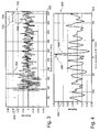
- Fig. 3 shows a diagram 300 having an abscissa 302 along which the time (samples at 44.1 kHz) are plotted. Along an ordinate 304, an amplitude is plotted.
- Fig. 3 shows a first curve 306 representing a left impulse response from the reference speaker 122 to the left ear 106.
- a second curve 308 shows a right impulse response from the reference loudspeaker 122 to the right ear 108.
- Fig. 4 shows a diagram 400 having an abscissa 402 along which the time (samples at 44.1 kHz) is plotted. Along an ordinate 404 the amplitude is plotted.
- Fig. 4 shows a curve 406 indicating a cross-correlation of the curves 306 and 308 shown in Fig. 3 , wherein an Interaural Time Difference (ITD) is shown as an arrow 408.
- ITD Interaural Time Difference
- Fig. 4 shows a cross-correlation of tf L with tf R .
- the time difference between ear L and ear R may be calculated in order to detect a possible left/right swap. This can (but does not have to) be done by means of a conventional system identification technique (such the well-know NLMS algorithm, Normalised Least Mean Squares filter) calculating the acoustical transfer functions between the reference loudspeaker 122 and the microphones 116, 118. The resulting left and right transfer functions (TF L and TF R respectively) are then cross-correlated and the time position of its maximum is the ITD between the ear L and ear R signals.
- a conventional system identification technique such the well-know NLMS algorithm, Normalised Least Mean Squares filter
- Another ITD calculation technique (not shown on the figure, but described in " Binaural positioning system for wearable augmented reality audio", Tikander, M.; Harma, A.; Karjalainen, M., Applications of Signal Processing to Audio and Acoustics, 2003 IEEE Workshop on., 19-22 Oct. 2003 pages 153 - 156 , Digital Object Identifier) and which may be implemented in an exemplary embodiment of the invention consists in cross-correlating ear L and ear R by L i . The ITD then equals the time difference between the maxima of the right and left cross-correlations.
- a positive (negative) ITD means that ear R (ear L ) is time delayed compared to ear L (ear R ).
- the reference loudspeaker 122 is on the left side, a left/right swap only occurs when the calculated ITD is negative.
- the ITD must be positive to operate a left/right swap.
- loudspeakers 122, 202, 204, 206, 208, 210 are playing simultaneously, the same process can be applied for some or each loudspeaker 122, 202, 204, 206, 208, 210. This may improve system reliability, especially in noisy environments.
Claims (12)
- Dispositif (100) pour le traitement de données audio, dans lequel le dispositif (100) comporte :une première unité de reproduction audio (102) adaptée de manière à reproduire une première partie des données audio et adaptée de manière à être attachée à l'oreille gauche (106) d'un utilisateur (110) ;une deuxième unité de reproduction audio (104) adaptée de manière à reproduire une deuxième partie des données audio et adaptée de manière à être attachée à l'oreille droite (108) de l'utilisateur (110) ;une unité de détection (112) adaptée de manière à détecter une inversion gauche/droite de la première unité de reproduction audio (102) et de la deuxième unité de reproduction audio (104) ;une unité de commande (114) adaptée de manière à commander la première unité de reproduction audio (102) pour qu'elle reproduise la deuxième partie des données audio et à commander la deuxième unité de reproduction audio (104) pour qu'elle reproduise la première partie des données audio en cas de détection d'inversion gauche/droite,dans lequel l'unité de détection (112) comporte une première unité de détection de signal (116) localisée dans une position de la première unité de reproduction audio (102) et adaptée de manière à détecter un premier signal de détection et dans lequel elle comporte une deuxième unité de détection de signal (118) localisée dans une position de la deuxième unité de reproduction audio (104) et adaptée de manière à détecter un deuxième signal de détection,dans lequel l'unité de détection (112) est adaptée de manière à détecter l'inversion gauche/droite en fonction du premier signal de détection et du deuxième signal de détection,dans lequel la première unité de détection de signal (116) comporte un premier microphone et la deuxième unité de détection de signal (118) comporte un deuxième microphone, caractérisé par le fait que la première unité de reproduction audio (102) et la deuxième unité de reproduction audio (104) sont adaptées pour une Réduction Active de Bruit,et le premier microphone et le deuxième microphone sont utilisés pour détecter le bruit d'environnement afin de permettre la manipulation correspondante d'un signal audio reproduit lié à la Réduction Active de Bruit.
- Dispositif (100) selon la revendication 1, dans lequel l'unité de détection (112) est adaptée de manière à détecter l'inversion gauche/droite en déterminant une différence temporelle entre le premier signal de détection détecté par la première unité de détection de signal (116) et le deuxième signal de détection détecté par la deuxième unité de détection de signal (118).
- Dispositif (100) selon la revendication 1, comprenant une unité d'émission de signal (122) adaptée de manière à émettre un signal de référence en vue de sa détection par la première unité de détection de signal (116) en tant que premier signal de détection et par la deuxième unité de détection de signal (118) en tant que deuxième signal de détection.
- Dispositif (100) selon la revendication 3, dans lequel l'unité d'émission de signal (122) est adaptée de manière à émettre un signal parmi le groupe formé d'un signal de référence audible et d'un signal de référence inaudible.
- Dispositif (100) selon la revendication 3, dans lequel l'unité d'émission de signal (122) comporte au moins une autre unité de reproduction audio agencée de manière à reproduire d'autres données audio indépendamment de la première unité de reproduction audio (102) et de la deuxième unité de reproduction audio (104), les autres données audio reproduites constituant le signal de référence.
- Dispositif (100) selon la revendication 3, dans lequel l'unité d'émission de signal (122) est installée de manière fixe dans une position de référencé prédéfinie.
- Dispositif (100) selon la revendication 1, adaptée comme un dispositif dans le groupe constitué d'un système de divertissement de banquette arrière pour un véhicule, d'un système pour salle de congrès comprenant un casque pour la traduction, et d'un système de divertissement pour avion.
- Dispositif (100) selon la revendication 1, dans lequel la première unité de reproduction audio (102) et la deuxième unité de reproduction audio (104) font partie du groupe constitué d'un casque, d'un casque à écouteurs et d'un écouteur.
- Dispositif (100) selon la revendication 1, réalisé comme un dispositif dans le groupe constitué d'un téléphone mobile, d'un dispositif d'aide auditive, d'un appareil de télévision, d'un enregistreur vidéo, d'un moniteur, d'une console de jeu, d'un ordinateur portable, d'un lecteur audio, d'un lecteur de DVD, d'un lecteur de CD, d'un lecteur multimédia à disque dur, d'un appareil de radio, d'un appareil de radio internet, d'un système de divertissement public, d'un lecteur MP3, d'un système de divertissement pour voiture, d'un système de communication médical, d'un système porté sur le corps, d'un dispositif de communication de discours, d'un système de home cinéma, d'un système de théâtre à la maison, d'un appareil de télévision à écran plat, d'un dispositif de création d'ambiance, d'un système d'enregistrement en studio et d'un système de music hall.
- Procédé de traitement de données audio, dans lequel le procédé comporte :la reproduction d'une première partie des données audio à l'aide d'une première unité de reproduction audio (102) destinée à être attachée à l'oreille gauche (106) d'un utilisateur (110) ;la reproduction d'une deuxième partie des données audio à l'aide d'une deuxième unité de reproduction audio (104) destinée à être attachée à l'oreille droite (108) de l'utilisateur (110) ;la détection, par une unité de détection, d'une inversion gauche/droite de la première unité de reproduction audio (102) et de la deuxième unité de reproduction audio (104) ;en cas de détection d'inversion gauche/droite, la commande de la première unité de reproduction audio (102) pour qu'elle reproduise la deuxième partie des données audio et la commande de la deuxième unité de reproduction audio (104) pour qu'elle reproduise la première partie des données audio,dans lequel l'unité de détection (112) comporte une première unité de détection de signal (116) localisée dans une position de la première unité de reproduction audio (102) et adaptée de manière à détecter un premier signal de détection, et comporte une deuxième unité de détection de signal (118) localisée dans une position de la deuxième unité de reproduction audio (104) et adaptée de manière à détecter un deuxième signal de détection,dans lequel l'unité de détection (112) est adaptée de manière à détecter l'inversion gauche/droite en fonction du premier signal de détection et du deuxième signal de détection,dans lequel la première unité de détection de signal (116) comporte un premier microphone et la deuxième unité de détection de signal (118) comporte un deuxième microphone, caractérisé par le fait que la première unité de reproduction audio (102) et la deuxième unité de reproduction audio (104) sont agencées pour une Réduction Active de Bruit,et le premier microphone et le deuxième microphone sont utilisés pour détecter le bruit d'environnement afin de permettre la manipulation correspondante d'un signal audio reproduit liée à la Réduction Active de Bruit.
- Support lisible par ordinateur sur lequel est stocké un programme informatique pour le traitement audio, lequel programme informatique, lorsqu'il est exécuté par un processeur (112, 114), est adaptée de manière à exécuter ou à commander un procédé selon la revendication 10.
- Elément de programme pour le traitement de données audio, lequel élément de programme, lorsqu'il est exécuté par un processeur (112, 114), est adaptée de manière à exécuter ou à commander un procédé selon à la revendication 10.
Priority Applications (3)
| Application Number | Priority Date | Filing Date | Title |
|---|---|---|---|
| EP09168012A EP2288178B1 (fr) | 2009-08-17 | 2009-08-17 | Dispositif et procédé pour le traitement de données audio |
| US12/855,557 US8787602B2 (en) | 2009-08-17 | 2010-08-12 | Device for and a method of processing audio data |
| CN2010102545211A CN101998222A (zh) | 2009-08-17 | 2010-08-13 | 处理音频数据的设备和方法 |
Applications Claiming Priority (1)
| Application Number | Priority Date | Filing Date | Title |
|---|---|---|---|
| EP09168012A EP2288178B1 (fr) | 2009-08-17 | 2009-08-17 | Dispositif et procédé pour le traitement de données audio |
Publications (2)
| Publication Number | Publication Date |
|---|---|
| EP2288178A1 EP2288178A1 (fr) | 2011-02-23 |
| EP2288178B1 true EP2288178B1 (fr) | 2012-06-06 |
Family
ID=41695863
Family Applications (1)
| Application Number | Title | Priority Date | Filing Date |
|---|---|---|---|
| EP09168012A Active EP2288178B1 (fr) | 2009-08-17 | 2009-08-17 | Dispositif et procédé pour le traitement de données audio |
Country Status (3)
| Country | Link |
|---|---|
| US (1) | US8787602B2 (fr) |
| EP (1) | EP2288178B1 (fr) |
| CN (1) | CN101998222A (fr) |
Families Citing this family (42)
| Publication number | Priority date | Publication date | Assignee | Title |
|---|---|---|---|---|
| DE202009009804U1 (de) * | 2009-07-17 | 2009-10-29 | Sennheiser Electronic Gmbh & Co. Kg | Headset und Hörer |
| US9357282B2 (en) * | 2011-03-31 | 2016-05-31 | Nanyang Technological University | Listening device and accompanying signal processing method |
| US9084058B2 (en) | 2011-12-29 | 2015-07-14 | Sonos, Inc. | Sound field calibration using listener localization |
| US20130279724A1 (en) * | 2012-04-19 | 2013-10-24 | Sony Computer Entertainment Inc. | Auto detection of headphone orientation |
| US9219460B2 (en) | 2014-03-17 | 2015-12-22 | Sonos, Inc. | Audio settings based on environment |
| US9106192B2 (en) | 2012-06-28 | 2015-08-11 | Sonos, Inc. | System and method for device playback calibration |
| US9113246B2 (en) | 2012-09-20 | 2015-08-18 | International Business Machines Corporation | Automated left-right headphone earpiece identifier |
| US9326058B2 (en) | 2012-09-26 | 2016-04-26 | Sony Corporation | Control method of mobile terminal apparatus |
| US9681219B2 (en) | 2013-03-07 | 2017-06-13 | Nokia Technologies Oy | Orientation free handsfree device |
| CN104080028B (zh) * | 2013-03-25 | 2016-08-17 | 联想(北京)有限公司 | 一种识别方法、电子设备及耳机 |
| US20150029112A1 (en) * | 2013-07-26 | 2015-01-29 | Nxp B.V. | Touch sensor |
| US10063982B2 (en) * | 2013-10-09 | 2018-08-28 | Voyetra Turtle Beach, Inc. | Method and system for a game headset with audio alerts based on audio track analysis |
| US9264839B2 (en) | 2014-03-17 | 2016-02-16 | Sonos, Inc. | Playback device configuration based on proximity detection |
| CN104125522A (zh) * | 2014-07-18 | 2014-10-29 | 北京智谷睿拓技术服务有限公司 | 声道配置方法、装置及用户设备 |
| US9910634B2 (en) * | 2014-09-09 | 2018-03-06 | Sonos, Inc. | Microphone calibration |
| US9952825B2 (en) | 2014-09-09 | 2018-04-24 | Sonos, Inc. | Audio processing algorithms |
| US9782672B2 (en) * | 2014-09-12 | 2017-10-10 | Voyetra Turtle Beach, Inc. | Gaming headset with enhanced off-screen awareness |
| TWI577193B (zh) * | 2015-03-19 | 2017-04-01 | 陳光超 | 耳膜助聽器 |
| US9640169B2 (en) * | 2015-06-25 | 2017-05-02 | Bose Corporation | Arraying speakers for a uniform driver field |
| WO2017049169A1 (fr) | 2015-09-17 | 2017-03-23 | Sonos, Inc. | Faciliter l'étalonnage d'un dispositif de lecture audio |
| US9693165B2 (en) | 2015-09-17 | 2017-06-27 | Sonos, Inc. | Validation of audio calibration using multi-dimensional motion check |
| US9743207B1 (en) | 2016-01-18 | 2017-08-22 | Sonos, Inc. | Calibration using multiple recording devices |
| US11106423B2 (en) | 2016-01-25 | 2021-08-31 | Sonos, Inc. | Evaluating calibration of a playback device |
| US10003899B2 (en) | 2016-01-25 | 2018-06-19 | Sonos, Inc. | Calibration with particular locations |
| US9706304B1 (en) * | 2016-03-29 | 2017-07-11 | Lenovo (Singapore) Pte. Ltd. | Systems and methods to control audio output for a particular ear of a user |
| US9860662B2 (en) | 2016-04-01 | 2018-01-02 | Sonos, Inc. | Updating playback device configuration information based on calibration data |
| US9864574B2 (en) | 2016-04-01 | 2018-01-09 | Sonos, Inc. | Playback device calibration based on representation spectral characteristics |
| US9763018B1 (en) | 2016-04-12 | 2017-09-12 | Sonos, Inc. | Calibration of audio playback devices |
| CN108886653B (zh) * | 2016-04-20 | 2020-07-28 | 华为技术有限公司 | 一种耳机声道控制方法、相关设备及系统 |
| US9794710B1 (en) | 2016-07-15 | 2017-10-17 | Sonos, Inc. | Spatial audio correction |
| US10372406B2 (en) | 2016-07-22 | 2019-08-06 | Sonos, Inc. | Calibration interface |
| US10205906B2 (en) | 2016-07-26 | 2019-02-12 | The Directv Group, Inc. | Method and apparatus to present multiple audio content |
| US10459684B2 (en) | 2016-08-05 | 2019-10-29 | Sonos, Inc. | Calibration of a playback device based on an estimated frequency response |
| GB201615538D0 (en) * | 2016-09-13 | 2016-10-26 | Nokia Technologies Oy | A method , apparatus and computer program for processing audio signals |
| KR102535726B1 (ko) | 2016-11-30 | 2023-05-24 | 삼성전자주식회사 | 이어폰 오장착 검출 방법, 이를 위한 전자 장치 및 저장 매체 |
| CN108519097A (zh) * | 2018-03-14 | 2018-09-11 | 联想(北京)有限公司 | 导航方法以及语音播放设备 |
| US10299061B1 (en) | 2018-08-28 | 2019-05-21 | Sonos, Inc. | Playback device calibration |
| US11206484B2 (en) | 2018-08-28 | 2021-12-21 | Sonos, Inc. | Passive speaker authentication |
| US11188721B2 (en) * | 2018-10-22 | 2021-11-30 | Andi D'oleo | Headphones for a real time natural language machine interpretation |
| DE102019202987A1 (de) * | 2019-03-05 | 2020-09-10 | Ford Global Technologies, Llc | Fahrzeug und Anordnung mikroelektromechanischer Systeme zur Signalwandlung in einem Fahrzeuginnenraum |
| US11221820B2 (en) * | 2019-03-20 | 2022-01-11 | Creative Technology Ltd | System and method for processing audio between multiple audio spaces |
| US10734965B1 (en) | 2019-08-12 | 2020-08-04 | Sonos, Inc. | Audio calibration of a portable playback device |
Family Cites Families (16)
| Publication number | Priority date | Publication date | Assignee | Title |
|---|---|---|---|---|
| EP0664660B1 (fr) * | 1990-01-19 | 2000-09-27 | Sony Corporation | Appareil de reproduction de signaux audio |
| US5434921A (en) * | 1994-02-25 | 1995-07-18 | Sony Electronics Inc. | Stereo image control circuit |
| JP3796776B2 (ja) * | 1995-09-28 | 2006-07-12 | ソニー株式会社 | 映像音声再生装置 |
| CN1398501A (zh) | 1999-10-14 | 2003-02-19 | 福纳克有限公司 | 听音器匹配方法及听音器 |
| JP3514231B2 (ja) * | 2000-10-27 | 2004-03-31 | 日本電気株式会社 | ヘッドホン装置 |
| US8208654B2 (en) * | 2001-10-30 | 2012-06-26 | Unwired Technology Llc | Noise cancellation for wireless audio distribution system |
| US7120256B2 (en) * | 2002-06-21 | 2006-10-10 | Dolby Laboratories Licensing Corporation | Audio testing system and method |
| DE10331757B4 (de) * | 2003-07-14 | 2005-12-08 | Micronas Gmbh | Audiowiedergabesystem mit einem Datenrückkanal |
| KR20060098366A (ko) * | 2003-09-22 | 2006-09-18 | 코닌클리케 필립스 일렉트로닉스 엔.브이. | 전기 장치, 시스템 및 방법 |
| JP2005333211A (ja) * | 2004-05-18 | 2005-12-02 | Sony Corp | 音響収録方法、音響収録再生方法、音響収録装置および音響再生装置 |
| GB0419346D0 (en) * | 2004-09-01 | 2004-09-29 | Smyth Stephen M F | Method and apparatus for improved headphone virtualisation |
| WO2007145121A1 (fr) * | 2006-06-13 | 2007-12-21 | Nikon Corporation | Écran monté sur la tête |
| US7555134B2 (en) * | 2006-09-01 | 2009-06-30 | Etymotic Research, Inc. | Antenna for miniature wireless devices and improved wireless earphones supported entirely by the ear canal |
| JP2008103827A (ja) * | 2006-10-17 | 2008-05-01 | Sharp Corp | ワイヤレスヘッドホン |
| US8050444B2 (en) * | 2007-01-19 | 2011-11-01 | Dale Trenton Smith | Adjustable mechanism for improving headset comfort |
| US7995770B1 (en) * | 2007-02-02 | 2011-08-09 | Jeffrey Franklin Simon | Apparatus and method for aligning and controlling reception of sound transmissions at locations distant from the sound source |
-
2009
- 2009-08-17 EP EP09168012A patent/EP2288178B1/fr active Active
-
2010
- 2010-08-12 US US12/855,557 patent/US8787602B2/en active Active
- 2010-08-13 CN CN2010102545211A patent/CN101998222A/zh active Pending
Also Published As
| Publication number | Publication date |
|---|---|
| EP2288178A1 (fr) | 2011-02-23 |
| CN101998222A (zh) | 2011-03-30 |
| US20110038484A1 (en) | 2011-02-17 |
| US8787602B2 (en) | 2014-07-22 |
Similar Documents
| Publication | Publication Date | Title |
|---|---|---|
| EP2288178B1 (fr) | Dispositif et procédé pour le traitement de données audio | |
| US11676568B2 (en) | Apparatus, method and computer program for adjustable noise cancellation | |
| EP3114854B1 (fr) | Circuit intégré et procédé pour améliorer la performance d'un transducteur audio d'après la détection d'un état du transducteur | |
| EP1540988B1 (fr) | Haut-parleurs intelligents | |
| US8199942B2 (en) | Targeted sound detection and generation for audio headset | |
| KR100878457B1 (ko) | 음상정위 장치 | |
| US20110144779A1 (en) | Data processing for a wearable apparatus | |
| JP3435141B2 (ja) | 音像定位装置、並びに音像定位装置を用いた会議装置、携帯電話機、音声再生装置、音声記録装置、情報端末装置、ゲーム機、通信および放送システム | |
| US20110188662A1 (en) | Method of rendering binaural stereo in a hearing aid system and a hearing aid system | |
| EP3468228B1 (fr) | Système auditif binauriculaire comportant une localisation des sources sonores | |
| JP6193844B2 (ja) | 選択可能な知覚空間的な音源の位置決めを備える聴覚装置 | |
| US20080170730A1 (en) | Tracking system using audio signals below threshold | |
| US20110150233A1 (en) | Device for and a method of processing a signal | |
| JP4735920B2 (ja) | 音響処理装置 | |
| US20220345845A1 (en) | Method, Systems and Apparatus for Hybrid Near/Far Virtualization for Enhanced Consumer Surround Sound | |
| EP2887695B1 (fr) | Dispositif d'audition à positionnement spatial perçu sélectionnable de sources acoustiques | |
| JP2006352728A (ja) | オーディオ装置 | |
| KR20020028918A (ko) | 오디오 시스템 | |
| US20200252721A1 (en) | Directional Sound Recording and Playback | |
| JP6972858B2 (ja) | 音響処理装置、プログラム及び方法 | |
| CN116367050A (zh) | 处理音频信号的方法、存储介质、电子设备和音频设备 | |
| EP3182723A1 (fr) | Distribution de signaux audio | |
| JP2010016525A (ja) | 音響処理装置および音響処理方法 | |
| JP2010034764A (ja) | 音響再生システム |
Legal Events
| Date | Code | Title | Description |
|---|---|---|---|
| PUAI | Public reference made under article 153(3) epc to a published international application that has entered the european phase |
Free format text: ORIGINAL CODE: 0009012 |
|
| AK | Designated contracting states |
Kind code of ref document: A1 Designated state(s): AT BE BG CH CY CZ DE DK EE ES FI FR GB GR HR HU IE IS IT LI LT LU LV MC MK MT NL NO PL PT RO SE SI SK SM TR |
|
| AX | Request for extension of the european patent |
Extension state: AL BA RS |
|
| 17P | Request for examination filed |
Effective date: 20110823 |
|
| 17Q | First examination report despatched |
Effective date: 20110919 |
|
| GRAP | Despatch of communication of intention to grant a patent |
Free format text: ORIGINAL CODE: EPIDOSNIGR1 |
|
| GRAS | Grant fee paid |
Free format text: ORIGINAL CODE: EPIDOSNIGR3 |
|
| GRAA | (expected) grant |
Free format text: ORIGINAL CODE: 0009210 |
|
| AK | Designated contracting states |
Kind code of ref document: B1 Designated state(s): AT BE BG CH CY CZ DE DK EE ES FI FR GB GR HR HU IE IS IT LI LT LU LV MC MK MT NL NO PL PT RO SE SI SK SM TR |
|
| REG | Reference to a national code |
Ref country code: GB Ref legal event code: FG4D |
|
| REG | Reference to a national code |
Ref country code: AT Ref legal event code: REF Ref document number: 561499 Country of ref document: AT Kind code of ref document: T Effective date: 20120615 Ref country code: CH Ref legal event code: EP |
|
| REG | Reference to a national code |
Ref country code: IE Ref legal event code: FG4D |
|
| REG | Reference to a national code |
Ref country code: DE Ref legal event code: R096 Ref document number: 602009007439 Country of ref document: DE Effective date: 20120802 |
|
| REG | Reference to a national code |
Ref country code: NL Ref legal event code: VDEP Effective date: 20120606 |
|
| PG25 | Lapsed in a contracting state [announced via postgrant information from national office to epo] |
Ref country code: NO Free format text: LAPSE BECAUSE OF FAILURE TO SUBMIT A TRANSLATION OF THE DESCRIPTION OR TO PAY THE FEE WITHIN THE PRESCRIBED TIME-LIMIT Effective date: 20120906 Ref country code: SE Free format text: LAPSE BECAUSE OF FAILURE TO SUBMIT A TRANSLATION OF THE DESCRIPTION OR TO PAY THE FEE WITHIN THE PRESCRIBED TIME-LIMIT Effective date: 20120606 Ref country code: CY Free format text: LAPSE BECAUSE OF FAILURE TO SUBMIT A TRANSLATION OF THE DESCRIPTION OR TO PAY THE FEE WITHIN THE PRESCRIBED TIME-LIMIT Effective date: 20120606 Ref country code: FI Free format text: LAPSE BECAUSE OF FAILURE TO SUBMIT A TRANSLATION OF THE DESCRIPTION OR TO PAY THE FEE WITHIN THE PRESCRIBED TIME-LIMIT Effective date: 20120606 Ref country code: LT Free format text: LAPSE BECAUSE OF FAILURE TO SUBMIT A TRANSLATION OF THE DESCRIPTION OR TO PAY THE FEE WITHIN THE PRESCRIBED TIME-LIMIT Effective date: 20120606 |
|
| REG | Reference to a national code |
Ref country code: AT Ref legal event code: MK05 Ref document number: 561499 Country of ref document: AT Kind code of ref document: T Effective date: 20120606 |
|
| REG | Reference to a national code |
Ref country code: LT Ref legal event code: MG4D Effective date: 20120606 |
|
| PG25 | Lapsed in a contracting state [announced via postgrant information from national office to epo] |
Ref country code: SI Free format text: LAPSE BECAUSE OF FAILURE TO SUBMIT A TRANSLATION OF THE DESCRIPTION OR TO PAY THE FEE WITHIN THE PRESCRIBED TIME-LIMIT Effective date: 20120606 Ref country code: GR Free format text: LAPSE BECAUSE OF FAILURE TO SUBMIT A TRANSLATION OF THE DESCRIPTION OR TO PAY THE FEE WITHIN THE PRESCRIBED TIME-LIMIT Effective date: 20120907 Ref country code: HR Free format text: LAPSE BECAUSE OF FAILURE TO SUBMIT A TRANSLATION OF THE DESCRIPTION OR TO PAY THE FEE WITHIN THE PRESCRIBED TIME-LIMIT Effective date: 20120606 Ref country code: LV Free format text: LAPSE BECAUSE OF FAILURE TO SUBMIT A TRANSLATION OF THE DESCRIPTION OR TO PAY THE FEE WITHIN THE PRESCRIBED TIME-LIMIT Effective date: 20120606 |
|
| PG25 | Lapsed in a contracting state [announced via postgrant information from national office to epo] |
Ref country code: IS Free format text: LAPSE BECAUSE OF FAILURE TO SUBMIT A TRANSLATION OF THE DESCRIPTION OR TO PAY THE FEE WITHIN THE PRESCRIBED TIME-LIMIT Effective date: 20121006 Ref country code: RO Free format text: LAPSE BECAUSE OF FAILURE TO SUBMIT A TRANSLATION OF THE DESCRIPTION OR TO PAY THE FEE WITHIN THE PRESCRIBED TIME-LIMIT Effective date: 20120606 Ref country code: NL Free format text: LAPSE BECAUSE OF FAILURE TO SUBMIT A TRANSLATION OF THE DESCRIPTION OR TO PAY THE FEE WITHIN THE PRESCRIBED TIME-LIMIT Effective date: 20120606 Ref country code: CZ Free format text: LAPSE BECAUSE OF FAILURE TO SUBMIT A TRANSLATION OF THE DESCRIPTION OR TO PAY THE FEE WITHIN THE PRESCRIBED TIME-LIMIT Effective date: 20120606 Ref country code: AT Free format text: LAPSE BECAUSE OF FAILURE TO SUBMIT A TRANSLATION OF THE DESCRIPTION OR TO PAY THE FEE WITHIN THE PRESCRIBED TIME-LIMIT Effective date: 20120606 Ref country code: BE Free format text: LAPSE BECAUSE OF FAILURE TO SUBMIT A TRANSLATION OF THE DESCRIPTION OR TO PAY THE FEE WITHIN THE PRESCRIBED TIME-LIMIT Effective date: 20120606 Ref country code: EE Free format text: LAPSE BECAUSE OF FAILURE TO SUBMIT A TRANSLATION OF THE DESCRIPTION OR TO PAY THE FEE WITHIN THE PRESCRIBED TIME-LIMIT Effective date: 20120606 Ref country code: SK Free format text: LAPSE BECAUSE OF FAILURE TO SUBMIT A TRANSLATION OF THE DESCRIPTION OR TO PAY THE FEE WITHIN THE PRESCRIBED TIME-LIMIT Effective date: 20120606 |
|
| PG25 | Lapsed in a contracting state [announced via postgrant information from national office to epo] |
Ref country code: PT Free format text: LAPSE BECAUSE OF FAILURE TO SUBMIT A TRANSLATION OF THE DESCRIPTION OR TO PAY THE FEE WITHIN THE PRESCRIBED TIME-LIMIT Effective date: 20121008 Ref country code: PL Free format text: LAPSE BECAUSE OF FAILURE TO SUBMIT A TRANSLATION OF THE DESCRIPTION OR TO PAY THE FEE WITHIN THE PRESCRIBED TIME-LIMIT Effective date: 20120606 Ref country code: IT Free format text: LAPSE BECAUSE OF FAILURE TO SUBMIT A TRANSLATION OF THE DESCRIPTION OR TO PAY THE FEE WITHIN THE PRESCRIBED TIME-LIMIT Effective date: 20120606 |
|
| PG25 | Lapsed in a contracting state [announced via postgrant information from national office to epo] |
Ref country code: MC Free format text: LAPSE BECAUSE OF NON-PAYMENT OF DUE FEES Effective date: 20120831 |
|
| PLBE | No opposition filed within time limit |
Free format text: ORIGINAL CODE: 0009261 |
|
| STAA | Information on the status of an ep patent application or granted ep patent |
Free format text: STATUS: NO OPPOSITION FILED WITHIN TIME LIMIT |
|
| PG25 | Lapsed in a contracting state [announced via postgrant information from national office to epo] |
Ref country code: DK Free format text: LAPSE BECAUSE OF FAILURE TO SUBMIT A TRANSLATION OF THE DESCRIPTION OR TO PAY THE FEE WITHIN THE PRESCRIBED TIME-LIMIT Effective date: 20120606 Ref country code: ES Free format text: LAPSE BECAUSE OF FAILURE TO SUBMIT A TRANSLATION OF THE DESCRIPTION OR TO PAY THE FEE WITHIN THE PRESCRIBED TIME-LIMIT Effective date: 20120917 |
|
| 26N | No opposition filed |
Effective date: 20130307 |
|
| REG | Reference to a national code |
Ref country code: IE Ref legal event code: MM4A |
|
| REG | Reference to a national code |
Ref country code: DE Ref legal event code: R097 Ref document number: 602009007439 Country of ref document: DE Effective date: 20130307 |
|
| PG25 | Lapsed in a contracting state [announced via postgrant information from national office to epo] |
Ref country code: BG Free format text: LAPSE BECAUSE OF FAILURE TO SUBMIT A TRANSLATION OF THE DESCRIPTION OR TO PAY THE FEE WITHIN THE PRESCRIBED TIME-LIMIT Effective date: 20120906 Ref country code: IE Free format text: LAPSE BECAUSE OF NON-PAYMENT OF DUE FEES Effective date: 20120817 |
|
| PG25 | Lapsed in a contracting state [announced via postgrant information from national office to epo] |
Ref country code: MT Free format text: LAPSE BECAUSE OF FAILURE TO SUBMIT A TRANSLATION OF THE DESCRIPTION OR TO PAY THE FEE WITHIN THE PRESCRIBED TIME-LIMIT Effective date: 20120606 |
|
| REG | Reference to a national code |
Ref country code: CH Ref legal event code: PL |
|
| PG25 | Lapsed in a contracting state [announced via postgrant information from national office to epo] |
Ref country code: CH Free format text: LAPSE BECAUSE OF NON-PAYMENT OF DUE FEES Effective date: 20130831 Ref country code: TR Free format text: LAPSE BECAUSE OF FAILURE TO SUBMIT A TRANSLATION OF THE DESCRIPTION OR TO PAY THE FEE WITHIN THE PRESCRIBED TIME-LIMIT Effective date: 20120606 Ref country code: LI Free format text: LAPSE BECAUSE OF NON-PAYMENT OF DUE FEES Effective date: 20130831 |
|
| PG25 | Lapsed in a contracting state [announced via postgrant information from national office to epo] |
Ref country code: SM Free format text: LAPSE BECAUSE OF FAILURE TO SUBMIT A TRANSLATION OF THE DESCRIPTION OR TO PAY THE FEE WITHIN THE PRESCRIBED TIME-LIMIT Effective date: 20120606 Ref country code: LU Free format text: LAPSE BECAUSE OF NON-PAYMENT OF DUE FEES Effective date: 20120817 |
|
| PG25 | Lapsed in a contracting state [announced via postgrant information from national office to epo] |
Ref country code: HU Free format text: LAPSE BECAUSE OF FAILURE TO SUBMIT A TRANSLATION OF THE DESCRIPTION OR TO PAY THE FEE WITHIN THE PRESCRIBED TIME-LIMIT Effective date: 20090817 |
|
| PG25 | Lapsed in a contracting state [announced via postgrant information from national office to epo] |
Ref country code: MK Free format text: LAPSE BECAUSE OF FAILURE TO SUBMIT A TRANSLATION OF THE DESCRIPTION OR TO PAY THE FEE WITHIN THE PRESCRIBED TIME-LIMIT Effective date: 20120606 |
|
| REG | Reference to a national code |
Ref country code: FR Ref legal event code: PLFP Year of fee payment: 8 |
|
| REG | Reference to a national code |
Ref country code: FR Ref legal event code: PLFP Year of fee payment: 9 |
|
| REG | Reference to a national code |
Ref country code: FR Ref legal event code: PLFP Year of fee payment: 10 |
|
| PGFP | Annual fee paid to national office [announced via postgrant information from national office to epo] |
Ref country code: GB Payment date: 20220721 Year of fee payment: 14 Ref country code: DE Payment date: 20220720 Year of fee payment: 14 |
|
| PGFP | Annual fee paid to national office [announced via postgrant information from national office to epo] |
Ref country code: FR Payment date: 20220721 Year of fee payment: 14 |
|
| REG | Reference to a national code |
Ref country code: DE Ref legal event code: R119 Ref document number: 602009007439 Country of ref document: DE |
|
| GBPC | Gb: european patent ceased through non-payment of renewal fee |
Effective date: 20230817 |