EP2288138A1 - Objekterkennungsvorrichtung für ein fahrzeug - Google Patents
Objekterkennungsvorrichtung für ein fahrzeug Download PDFInfo
- Publication number
- EP2288138A1 EP2288138A1 EP09746571A EP09746571A EP2288138A1 EP 2288138 A1 EP2288138 A1 EP 2288138A1 EP 09746571 A EP09746571 A EP 09746571A EP 09746571 A EP09746571 A EP 09746571A EP 2288138 A1 EP2288138 A1 EP 2288138A1
- Authority
- EP
- European Patent Office
- Prior art keywords
- image
- processing
- vehicle
- region
- processing candidate
- Prior art date
- Legal status (The legal status is an assumption and is not a legal conclusion. Google has not performed a legal analysis and makes no representation as to the accuracy of the status listed.)
- Withdrawn
Links
Images


Classifications
-
- G—PHYSICS
- G01—MEASURING; TESTING
- G01S—RADIO DIRECTION-FINDING; RADIO NAVIGATION; DETERMINING DISTANCE OR VELOCITY BY USE OF RADIO WAVES; LOCATING OR PRESENCE-DETECTING BY USE OF THE REFLECTION OR RERADIATION OF RADIO WAVES; ANALOGOUS ARRANGEMENTS USING OTHER WAVES
- G01S13/00—Systems using the reflection or reradiation of radio waves, e.g. radar systems; Analogous systems using reflection or reradiation of waves whose nature or wavelength is irrelevant or unspecified
- G01S13/88—Radar or analogous systems specially adapted for specific applications
- G01S13/93—Radar or analogous systems specially adapted for specific applications for anti-collision purposes
- G01S13/931—Radar or analogous systems specially adapted for specific applications for anti-collision purposes of land vehicles
-
- G—PHYSICS
- G01—MEASURING; TESTING
- G01S—RADIO DIRECTION-FINDING; RADIO NAVIGATION; DETERMINING DISTANCE OR VELOCITY BY USE OF RADIO WAVES; LOCATING OR PRESENCE-DETECTING BY USE OF THE REFLECTION OR RERADIATION OF RADIO WAVES; ANALOGOUS ARRANGEMENTS USING OTHER WAVES
- G01S13/00—Systems using the reflection or reradiation of radio waves, e.g. radar systems; Analogous systems using reflection or reradiation of waves whose nature or wavelength is irrelevant or unspecified
- G01S13/86—Combinations of radar systems with non-radar systems, e.g. sonar, direction finder
- G01S13/867—Combination of radar systems with cameras
-
- G—PHYSICS
- G01—MEASURING; TESTING
- G01S—RADIO DIRECTION-FINDING; RADIO NAVIGATION; DETERMINING DISTANCE OR VELOCITY BY USE OF RADIO WAVES; LOCATING OR PRESENCE-DETECTING BY USE OF THE REFLECTION OR RERADIATION OF RADIO WAVES; ANALOGOUS ARRANGEMENTS USING OTHER WAVES
- G01S17/00—Systems using the reflection or reradiation of electromagnetic waves other than radio waves, e.g. lidar systems
- G01S17/86—Combinations of lidar systems with systems other than lidar, radar or sonar, e.g. with direction finders
-
- G—PHYSICS
- G01—MEASURING; TESTING
- G01S—RADIO DIRECTION-FINDING; RADIO NAVIGATION; DETERMINING DISTANCE OR VELOCITY BY USE OF RADIO WAVES; LOCATING OR PRESENCE-DETECTING BY USE OF THE REFLECTION OR RERADIATION OF RADIO WAVES; ANALOGOUS ARRANGEMENTS USING OTHER WAVES
- G01S17/00—Systems using the reflection or reradiation of electromagnetic waves other than radio waves, e.g. lidar systems
- G01S17/88—Lidar systems specially adapted for specific applications
- G01S17/93—Lidar systems specially adapted for specific applications for anti-collision purposes
- G01S17/931—Lidar systems specially adapted for specific applications for anti-collision purposes of land vehicles
-
- G—PHYSICS
- G06—COMPUTING; CALCULATING OR COUNTING
- G06V—IMAGE OR VIDEO RECOGNITION OR UNDERSTANDING
- G06V20/00—Scenes; Scene-specific elements
- G06V20/50—Context or environment of the image
- G06V20/56—Context or environment of the image exterior to a vehicle by using sensors mounted on the vehicle
- G06V20/58—Recognition of moving objects or obstacles, e.g. vehicles or pedestrians; Recognition of traffic objects, e.g. traffic signs, traffic lights or roads
-
- B—PERFORMING OPERATIONS; TRANSPORTING
- B60—VEHICLES IN GENERAL
- B60R—VEHICLES, VEHICLE FITTINGS, OR VEHICLE PARTS, NOT OTHERWISE PROVIDED FOR
- B60R21/00—Arrangements or fittings on vehicles for protecting or preventing injuries to occupants or pedestrians in case of accidents or other traffic risks
- B60R21/01—Electrical circuits for triggering passive safety arrangements, e.g. airbags, safety belt tighteners, in case of vehicle accidents or impending vehicle accidents
- B60R2021/01204—Actuation parameters of safety arrangents
- B60R2021/01252—Devices other than bags
- B60R2021/01259—Brakes
-
- B—PERFORMING OPERATIONS; TRANSPORTING
- B60—VEHICLES IN GENERAL
- B60R—VEHICLES, VEHICLE FITTINGS, OR VEHICLE PARTS, NOT OTHERWISE PROVIDED FOR
- B60R21/00—Arrangements or fittings on vehicles for protecting or preventing injuries to occupants or pedestrians in case of accidents or other traffic risks
- B60R21/01—Electrical circuits for triggering passive safety arrangements, e.g. airbags, safety belt tighteners, in case of vehicle accidents or impending vehicle accidents
- B60R21/013—Electrical circuits for triggering passive safety arrangements, e.g. airbags, safety belt tighteners, in case of vehicle accidents or impending vehicle accidents including means for detecting collisions, impending collisions or roll-over
- B60R21/0134—Electrical circuits for triggering passive safety arrangements, e.g. airbags, safety belt tighteners, in case of vehicle accidents or impending vehicle accidents including means for detecting collisions, impending collisions or roll-over responsive to imminent contact with an obstacle, e.g. using radar systems
-
- G—PHYSICS
- G01—MEASURING; TESTING
- G01S—RADIO DIRECTION-FINDING; RADIO NAVIGATION; DETERMINING DISTANCE OR VELOCITY BY USE OF RADIO WAVES; LOCATING OR PRESENCE-DETECTING BY USE OF THE REFLECTION OR RERADIATION OF RADIO WAVES; ANALOGOUS ARRANGEMENTS USING OTHER WAVES
- G01S13/00—Systems using the reflection or reradiation of radio waves, e.g. radar systems; Analogous systems using reflection or reradiation of waves whose nature or wavelength is irrelevant or unspecified
- G01S13/88—Radar or analogous systems specially adapted for specific applications
- G01S13/93—Radar or analogous systems specially adapted for specific applications for anti-collision purposes
- G01S13/931—Radar or analogous systems specially adapted for specific applications for anti-collision purposes of land vehicles
- G01S2013/93185—Controlling the brakes
-
- G—PHYSICS
- G01—MEASURING; TESTING
- G01S—RADIO DIRECTION-FINDING; RADIO NAVIGATION; DETERMINING DISTANCE OR VELOCITY BY USE OF RADIO WAVES; LOCATING OR PRESENCE-DETECTING BY USE OF THE REFLECTION OR RERADIATION OF RADIO WAVES; ANALOGOUS ARRANGEMENTS USING OTHER WAVES
- G01S13/00—Systems using the reflection or reradiation of radio waves, e.g. radar systems; Analogous systems using reflection or reradiation of waves whose nature or wavelength is irrelevant or unspecified
- G01S13/88—Radar or analogous systems specially adapted for specific applications
- G01S13/93—Radar or analogous systems specially adapted for specific applications for anti-collision purposes
- G01S13/931—Radar or analogous systems specially adapted for specific applications for anti-collision purposes of land vehicles
- G01S2013/932—Radar or analogous systems specially adapted for specific applications for anti-collision purposes of land vehicles using own vehicle data, e.g. ground speed, steering wheel direction
Definitions
- the present invention relates to an on-vehicle object detection device for detecting an object ahead of an own vehicle, which may possibly collide with the own vehicle.
- a preventive safety system is a system which operates before an accident and, for example, a pre-crash safety system has been put into practical use, which alerts the driver with a warning when a collision with an object ahead of the own vehicle becomes possible, and mitigates the damage of the occupant by automatic braking when the collision becomes unavoidable.
- Patent Document 1 describes a method that uses a laser radar and a camera, and judges the presence of a low reflectance object which has a low reflectance to a laser beam, such as a pedestrian, by a pattern matching using a camera image.
- Patent Document 1 JP Patent Publication (Kokai) No. 2007-240314 A (2007 ).
- the radar will become to react to various objects and the subjects of image processing increase thereby increasing the processing load of the device.
- the radar detects objects which have no possibility of colliding with the own vehicle (hereafter, referred to as a non-solid object) such as road paints, manholes, and cat's eyes, when an erroneous detection for such a non-solid object occurs in the image processing, a warning and automatic braking will be actuated in the above described pre-crash safety system thereby leading to a deterioration of safety.
- a non-solid object such as road paints, manholes, and cat's eyes
- the present invention has been made in view of the above described problems, and has its object to provide an on-vehicle object detection device which achieves both reduction of the load of image processing and reduction of erroneous detection of non-solid objects.
- An on-vehicle object detection device of the present invention which is the means for solving the above described problems, selects a processing candidate based on the distance from the own vehicle to an object and a forward-view image of the own vehicle, and determines if the processing candidate is a predetermined solid object which is set in advance, based on the distance to the processing candidate and the forward-view image.
- the determination of a solid object is performed on selected processing candidates, the number of execution of the processing to determine a solid object can be reduced. Therefore, the processing load for the entire device can be reduced. Moreover, in the processing to determine a solid object, an image which has more information can be used to judge a solid object, and erroneous detection for non-solid objects can be reduced.
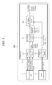
- Figure 1 is a block diagram of an on-vehicle object detection device 100 in the first embodiment.
- the on-vehicle object detection device 100 which is to be equipped on an automobile, is made up of a measurement unit 1, an image capturing unit 2, and a control unit 3.
- the measurement unit 1 is an apparatus that detects an object existent ahead of an own vehicle by using a laser radar, a millimeter-wave radar and the like, and measures a relative distance between the own vehicle and the object (for example, the distance in Y axis along the fore-and-aft direction of the vehicle body), a lateral position of the object (for example, the distance in X axis along the vehicle width direction), and the width of the object.
- the measurement result of the measurement unit 1 is inputted into the control unit 3 as object information.
- the measurement unit 1 may either directly input the signal of object information, or transfer it by communication by use of LAN (Local Area Network), to the control unit 3.
- LAN Local Area Network
- the image capturing unit 2 which is attached to a position where the image of the forward view from the own vehicle can be picked up, is an apparatus that converts the forward-view image, which photographed the forward view from the own vehicle by using an image pickup element such as CCD and CMOS, etc., into a signal of digital values.
- the signal of digital values may be either directly written on a RAM in the control unit 3 as digital values, or converted into an analog signal to be inputted into the control unit 3. Note that it is supposed that the forward-view image taken herein contains an object detected by the measurement unit 1.
- the control unit 3 is programmed with a predetermined processing and repeatedly executes the processing on a predetermined cycle.
- the control unit 3 includes object information acquisition means 31, image information acquisition means 32, processing candidate selection means 33, and solid object determination means 34 as internal functions.
- the object information acquisition means 31 acquires object information (relative distance PY0[i], lateral position PX0[i], and width WD0[i]) of an object ahead of the own vehicle according to a detected signal of the measurement unit 1.
- object information relative distance PY0[i], lateral position PX0[i], and width WD0[i]
- i is the ID number of each object when a plurality of objects are being detected.
- the image information acquisition means 32 acquires image information IMG[x][y] of a forward-view image that captures the forward-view from the own vehicle based on the signal of the image capturing unit 2.
- the image information IMG[x][y] is a two-dimensional array, in which X and y represent coordinates of the image, respectively.
- the processing candidate selection means 33 selects a processing candidate based on the object information (relative distance PY0[i], lateral position PX0[i], and width WD0[i]) acquired at the object information acquisition means 31 and the image information IMG[x][y] acquired at the image information acquisition means 32, and calculates processing candidate information (relative distance PY1[i], lateral position PX1[i], and width WD1[i]) of the selected processing candidate.
- "i" is the ID number of each processing candidate when a plurality of processing candidates are being selected. Note that the method of selecting a processing candidate and the method of calculating processing candidate information will be described later.
- the solid object determination means 34 determines whether or not the processing candidate is a predetermined solid object such as a human, etc. based on the processing candidate information (relative distance PY1[i], lateral position PX1[i], and width WD1[i]) of the processing candidate selected at the processing candidate selection means 33 and the image information IMG[x][y] acquired at the image information acquisition means 32, and calculates the solid object information (relative distance PY2[i], lateral position PX2[i], and width WD2[i]) of the solid object that has been determined to be a predetermined solid object.
- "i" is the ID number of each solid object when a plurality of solid objects are being detected. Note that the method of determining a solid object and the method of calculating solid object information will be described later.
- Figure 2 is a flowchart illustrating the processing content of the processing candidate selection means 33.
- step S201 the object information (PY0[i], PX0[i], and WD0[i]) acquired by the object information acquisition means 31 is read in. Then, at step S202, "0" is substituted into a processing candidate number j for initialization. Thereafter, steps S203 to S206 to be described below will be repeated according to the number of objects acquired by the object information acquisition means 31.
- an image processing region on an image is set based on the object information and a camera geometry model (relationship between a position on an image and an actual position).
- the process proceeds to step S204, and image processing such as pattern matching that scans within the image processing region is executed to detect an object on the image.
- image processing algorithm to be used at step S204 is referred to as a first algorithm. Note that the content of the first algorithm will be described later.
- step S205 a determination is made on whether or not an object is detected in the image processing region.
- the process proceeds to step S206, and the concerned object is selected as a processing candidate and the relative distance PY1[j], lateral position PX1[j]], and width WD1[j] of the object are recorded as processing candidate information, thereafter adding 1 to the processing candidate number j.
- step S207 the processing candidate information (all the recorded relative distances PY1[j], lateral positions PX1[j], widths WD1[j]) of the recorded processing candidate is outputted to the solid object determination means 34 thereby finishing the process.
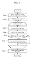
- Figure 3 is a flowchart illustrating the processing content of the solid object determination means 34.
- step S301 the processing candidate information (PY1[i], PX1[i], and WD1[i]) of the processing candidate selected by the processing candidate selection means 33 is read in. Then, at step S302, "0" is substituted into a solid object number j for initialization. Thereafter, steps S303 to S306 to be described below will be repeated according to the number of processing candidates that have been read in.
- an image processing region on an image is set based on processing candidate information and a camera geometry model.
- the process proceeds to step S304, and image processing such as pattern matching that scans within the image processing region is executed to detect solid objects on the image.
- image processing algorithm to be used at step S304 is referred to as a second algorithm. Note that the content of the second algorithm will be described later.
- step S305 a determination is made on whether or not a solid object of the detection target is detected.
- the process proceeds to step S306, and based on the judgment that the object is a solid object which has a possibility of colliding with the own vehicle, the relative distance PY2[j], lateral position PX2[j], width WD2[j] thereof are recorded and "1" is added to the solid object number j.
- step S307 the solid object information (all the recorded relative distances PY2[j], lateral positions PX2[j], and widths WD2[j]) of the recorded solid object is outputted from the control unit 3 to the outside, thereby finishing the process.
- Examples of the method of detecting a pedestrian include a method by template matching in which a plurality of templates that are representative of pedestrian patterns are prepared and the degree of matching is determined by performing a differential accumulation operation or a normalized correlation operation, or a method of performing pattern recognition by using a discriminator such as a neural network.
- the present embodiment will adopt the latter method of determination by using a discriminator.
- the size of the discriminator will not depend on the size of the database of sources. Note that, a database for creating a discriminator is referred to as teacher data.
- the discriminator 5 used in the present embodiment determines whether or not a pedestrian is present based on the direction and magnitude of gray-scale gradient in a plurality of subregions 52[n] placed in a predetermined portion in an image.
- Each subregion 52[n] sums up and outputs the magnitudes of gray-scale gradient in a particular direction at a predetermined position within the image 50.
- this output is referred to as a local edge strength.
- a filtering processing is performed by a filtering processing unit 51 such as a Sobel filter and the like, and images 50[n] having a magnitude and a direction of gray-scale gradient are outputted, respectively. Then, in a subregion 52[n] placed in a predetermined portion of each image 50[n], a local edge strength is calculated by using calculated magnitudes and directions of gray-scale gradient.
- a filtering processing unit 51 such as a Sobel filter and the like
- the direction of the gray-scale gradient corresponding to each one pixel in the subregion 52[n] is referred, and the magnitudes of gray-scale gradient at corresponding positions of pixels of which direction is the same as the direction predetermined for each subregion 52[n] are summed up.
- the magnitudes of gray-scale gradient at corresponding positions of pixels of which direction is the same as the direction predetermined for each subregion 52[n] are summed up.
- 40 subregions 52[n] are placed, 40 values of local edge strength LEWC[0] to LEWC[39] are obtained.
- each local edge strength is subjected to thresholding with a corresponding threshold value THWC[0] to THWC[39] to be converted into a binary number of "1" or "0”, is multiplied by a weight WWC[0] to WWC[39] at a corresponding weighting unit 54[n] to be outputted to a summation unit SUMSC55.
- the 40 values inputted from each weighting unit 54[n] are summed up by the summation unit SUMSC55, and are subjected to thresholding with a final threshold value THSC at the final determination processing unit 56 to be outputted as "1" or "0".
- the number, position, size, and direction of gray-scale gradient of the subregion 52[n] which are parameters for calculating each local edge strength LEWC[0] to LEWC[39] in the discriminator 5; the threshold values THWC[0] to THWC[39] of local edge strength in the subregion determination processing unit 53[n]; the weights WWC[0] to WWC[39] of the weighting unit 54[n]; the final threshold value THSC of the final determination processing unit 56; and the like are adjusted, by using teacher data, to output "1" when the input image 50 to the discriminator 5 is a pedestrian, and "0" when it is not a pedestrian.
- the adjustment may be performed by using machine learning means such as AdaBoost or performed manually.
- the adjustment method of the above described parameters by use of AdaBoost is as follows.
- a local edge which is calculated from the position, size, and direction of gray-scale gradient of a certain subregion 52, is represented as cLEWC[m].
- m is the ID number of each local edge.
- a plurality of (for example, one million kinds of) local edge strengths each having a different position, size, and direction of gray-scale gradient of a subregion 52 are prepared, and the value cLEWC[m] of each local edge strength is calculated from all the teacher data to determine each threshold value cTHWC[m].
- the threshold value cTHWC[m] is selected to be the value which can best separate the teacher data for pedestrian from the teacher data for non-pedestrian.
- nPD is the ID number of each teacher data for pedestrian
- nBG is the ID number of each teacher data for non-pedestrian.
- the erroneous detection rate cERWC[m] is the total of the weights of the teacher data for pedestrian in which the result of thresholding the local edge strength cLEWC[m] thereof with a threshold value cTHWC[m] gives non-pedestrian, or the teacher data for non-pedestrian in which the result of thresholding the local edge strength cLEWC[m] thereof with a threshold value cTHWC[m] gives pedestrian, that is, the teacher data in which the result of the thresholding is different from actuality.
- the weight of each teacher data is updated.
- the image size is converted such that the size of a pedestrian that appears on an image within a given image processing region becomes 16 dots long and 12 dots wide.
- a search is performed by the following means.
- a 16 ⁇ 12 window is set in the upper left of the image after conversion and the image in this window is subjected to the above described discriminator 5. Then, the window is successively subjected to the discriminator 5 while being shifted rightward by 1 dot by 1 dot, and when the window reaches the right end, the window is moved down by 1 dot to be returned to the left end and is again successively subjected to the discriminator 5 while being moved rightward again.
- This search is repeated until the window reaches the lower right. In this search, a pedestrian will be present in a place where the output of the discriminator 5 is "1".
- four discriminators 5, each having a different size of input image 50 are prepared, with the first algorithm utilizing the first discriminator 5 having the smallest size of the input image 50, and the second algorithm utilizing the remaining three kinds, that is, the second to the fourth discriminators 5.
- the second to the fourth discriminators 5 are configured to have a larger size of the input image 50 than that of the first discriminator 5, and to have gradually larger sizes in the order of the second to the fourth discriminators 5.
- the first algorithm converts the image size of an image in the image processing region, assuming that a pedestrian is present in the image of the image processing region set by the processing candidate selection means 33 at step S203 and using a relative distance to an object and a camera geometry model, such that the size of the image is the same as that of an image in which a pedestrian is present at a position a preset distance forwardly away from the own vehicle.
- the first discriminator 5 is prepared which can detect a pedestrian present at a position 40 meters forwardly away from the own vehicle, and an image in the image processing region set at step S203 is converted by using a camera geometry model so as to have the same size as that of an image in which a pedestrian is present at a position 40 meters forwardly away from the own vehicle, so that a pedestrian is detected by the above described search method.
- the present embodiment is predicated on that a pedestrian is present between the own vehicle and a point 40 meters forwardly away from the own vehicle. Therefore, at step S203, the image in the image processing region will be converted in a contracting direction.
- processing candidate information (relative distance PY1[i], lateral position PX1[i], and width WD1[i]) is updated by using a camera geometry model.
- the second algorithm assumes that a pedestrian is present in an image of the image processing region set at step S303, and converts the image size of the image in the image processing region such that the image size corresponds to the discriminator 5 which is most suitable for searching the pedestrian in the image, by using the relative distance to an object and a camera geometry model.
- a second to a fourth discriminators 5 that can detect pedestrians located at positions 10 m, 20 m, and 30 m forwardly away from the own vehicle are prepared, respectively. Then, when a processing candidate is present at a position more than 20 m away from the own vehicle, the image of the image processing region set at step S303 is converted into an image size of the image at 30 m point, and the fourth discriminator 5 is used to search a pedestrian by the above described search method.
- the image of the image processing region is converted into an image size of the image of 20 m point, and the third discriminator 5 is used to search a pedestrian by the above described search method.
- the image of the image processing region is converted into an image size of the image of 10 m point, and the second discriminator 5 is used to search a pedestrian by the above described search method.
- the detection position of the pedestrian on the image after conversion is converted into a position on the image before conversion, and the solid object information (relative distance PY2[i], lateral position PX2[i], and width WD2[i]) is updated by using a camera geometry model.
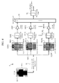
- an object P that is detected by the measurement means 1 is identified on a forward-view image 60, and the image portion including the object P is set as an image processing region A (S61).
- the position of the object P on the forward-view image 60 is identified based on the object information of the object P detected by the measurement unit 1 and a camera geometry model.
- object P1 pedestrian
- object P2 manhole
- object 3 utility pole
- the first algorithm is used to perform image processing on the image in the image processing region A, and an image processing candidate is selected according to the result of the image processing (S62).
- the image in each image processing region A is converted to be reduced to the same size as that of the image of a human that is present at a position 40 m forwardly away from the own vehicle, and a search is performed on the reduced image to select a processing candidate.
- the processing candidate (pedestrian) is searched in the image B that is reduced from the image of the image processing region A, the search region can be further reduced than in the case in which the processing candidate is searched in the image processing region A. Therefore, the processing load of the control unit 3 can be reduced and also a rapid search is possible.
- the position of the processing candidate Q in the image B is converted into a position on the original forward-view image 60 and the processing candidate information (PY1[i], PX1[i], and WD1[i]) of the processing candidate Q is updated from the object information of the corresponding object P.
- processing candidates Q1 and Q2 are selected in regions C1 and C2 in the images B1 and B2, out of the images B1 to B3 which are reduced from the images of the image processing regions A1 to A3. And the positions of the processing candidates Q1 and Q2 are converted into the positions on the original forward-view image 60 (see Figure 5(c) ) and the processing candidate information is updated.
- an image processing region D is set in the forward-view image 60 (S63), and an image processing using the second algorithm is performed on the image of the image processing region D to determine whether or not the processing candidate Q is a predetermined solid object (pedestrian) (S64).
- the second to the fourth discriminators 5 for 10 m, 20 m, and 30 m are selectively used depending on the relative distance to a processing object, the size of the image to be processed will vary depending on the relative distance to the processing candidate.
- the object P1 in the image processing region D1 out of the image processing regions D1 and D2 has been determined to be a pedestrian.
- the range in which the second algorithm is executed can be narrowed by the first algorithm, thereby enabling the reduction of the processing load of the control unit 3. That is, since processing candidates are selected first and a determination of whether or not the processing candidates are solid objects is made on the selected processing candidates, it is possible to reduce the number of executions of the image processing of the second algorithm, the processing load of which is larger than that of the image processing of the first algorithm, consequently reducing the processing load of the control unit 3.
- the search range can be made smaller than in the search of the image in an image processing region of a forward-view image, enabling a reduction of the processing load of the control unit 3 and also a rapid search.
- the solid object determination means 34 since a solid object is determined by the second algorithm using an image of higher resolution than that of the image to be used when the processing candidate selection means 33 selects processing candidates, it is possible to reduce erroneous detections.
- the second to the fourth discriminators 5 are selectively used by the second algorithm according to the relative distance between the own vehicle and the processing candidate, it is possible to reduce more erroneous detections for closer objects. That is, since in an image of a forward view of own vehicle taken by a camera, an object closer to the own vehicle appears larger in the image, thus providing more information, more information can be used for objects closer to the own vehicle by selectively using the discriminators 5 according to the distance, and as a result, erroneous detections can be reduced.
- the number of the discriminators 5 used in the first algorithm and the second algorithm are not limited to one and three, respectively, and any number of them may be used.
- the size of the input image 50 of each discriminator 5 is not limited to the sizes at distances of 10 m, 20 m, 30 m, and 40 m, and may be set to images at any distance.
- the discriminator 5 to be used for the detection of a pedestrian will not be limited to the method adopted in the present embodiment. Neural network discriminators, the Support Vector Machine discriminator, the Bayes discriminator, and the like may be used.
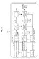
- FIG. 6 is a block diagram showing an embodiment of an on-vehicle object detection device 101 of another form.
- the on-vehicle object detection device 101 is made up of a measurement unit 1, an image capturing unit 2, and a control unit 4.
- the control unit 4 is programmed with a predetermined processing, and executes repetitive processing on a predetermined cycle. The processing different from that of the control unit 3 will be described below.
- Predicted travel path setting means 41 acquires own vehicle information such as a vehicle speed Vsp, a steering angle ⁇ , a yaw rate ⁇ , and the like according to detection signals of a vehicle speed sensor, a steering angle sensor, a yaw rate sensor, and like, and calculates a predicted travel path of own vehicle according to the own vehicle information.
- a turning radius R is calculated as the predicted travel path of the own vehicle. Note that the method of calculating the turning radius R will be described later.
- Processing candidate selection region setting means 42 sets a processing candidate selection region for processing candidate selection means 44 executing selection processing according to the predicted travel path of the own vehicle acquired at the predicted travel path setting means 41. Note that the method of setting a processing candidate selection region will be described later.
- Solid object determination region setting means 43 sets a solid object determination region for solid object determination means 45 executing determination processing according to the processing candidate selection region acquired at the processing candidate selection region setting means 42. Note that the method of setting a solid object determination region will be described later.
- the processing candidate selection means 44 calculates processing candidate information (relative distance PY1[i], lateral position PX1[i], and width WD1[i]) according to the object information (relative distance PY0[i], lateral position PX0[i], and width WD0[i]) acquired at object information acquisition means 31, image information IMG[x][y] acquired at image information acquisition means 32, and a processing candidate selection region set at the processing candidate selection region setting means 42.
- "i" indicates the ID number of each processing candidate when a plurality of processing candidates are being selected. Note that the method of calculating a processing candidate will be described later.
- the solid object determination means 45 calculates solid object information (relative distance PY2[i], lateral position PX2[i], and width WD2[i]) according to the image information IMG[x][y] of the image acquired at the image information acquisition means 32, the processing candidate information (relative distance PY1[i], lateral position PX1[i], and width WD1[i]) calculated at the processing candidate selection means 44, and the solid object determination region set at the solid object determination region setting means 43.
- "i" indicates the ID number of each solid object when a plurality of solid objects are being detected. Note that the method of calculating object determination will be described later.
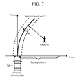
- Figure 7 is a schematic diagram showing processing contents of the predicted travel path setting means 41.
- a predicted travel path T can be approximated by a circular arc of a turning radius R passing through the origin O.
- the turning radius R can be represented by Expression (1) using a steering angle ⁇ , a speed Vsp, a stability factor A, a wheel base B, and a steering gear ratio Gs of the own vehicle 70.
- the turning radius R 1 + AVsp 2 ⁇ B ⁇ Gs / ⁇
- the stability factor A sign conditions of which dominate the steering characteristics of a vehicle, is an important value to provide an indicator indicating the magnitude of the change depending on the speed of steady-state circular turning of the vehicle.
- the turning radius R changes in proportion to the square of the speed Vsp of the own vehicle 70 with the stability factor A being a coefficient.
- the turning radius R can be represented by Expression (2) using the vehicle speed Vsp and the yaw rate ⁇ .
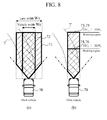
- the processing candidate selection region setting means 42 sets a processing candidate selection region 71, for example, such that the region has a width of a lane width Wn on the predicted travel path T as shown in Figure 8(a) .
- the solid object determination region setting means 43 sets a solid object determination region 72, for example, such that the region is laid on the predicted travel path T having a width of an own vehicle width Wc as shown in Figure 8(a) according to the processing candidate selection region 71 set by the processing candidate selection region setting means 42.
- Figure 8(b) shows an example in which time spans, TTCa and TTCb, are specified and a configuration is made such that a warning region where a time-to-collision, which is calculated by dividing the relative distance to an object ahead of the own vehicle 70 by a relative speed, is no more than TTCa is set as a processing candidate selection region 73, and a braking region where the time-to-collision is no more than TTCb is set as a solid object determination region 74.
- time spans, THWa and THWb may be specified to configure such that by using predicted positions obtained from the own vehicle speed, and THWa and THWb, a region as far as to an arrival position of the own vehicle at an elapse of THWa is set as a candidate selection region 75, and a region as far as to an arrival position of the own vehicle at an elapse of THWb is set as a solid object determination region 76.
- the method of setting the processing candidate selection regions 71, 73 and 75 and the solid object determination regions 72, 74 and 76 is not limited to this, and the region may be set to a portion where the recognition result of a lane recognition apparatus, which recognizes the traveling lane of the own vehicle 70 from an image obtained by an image capturing unit 2 such as a camera, and the predicted travel path T are superposed, or may be set according to the distance to an object ahead of the own vehicle 70 which is detected by a measurement unit 1 such as a radar.
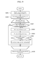
- Figure 9 is a flowchart showing the processing content of the processing candidate selection means 44.
- step S401 object information (PY0[i], PX0[i], and WD0[i]) detected by the object information acquisition means 31 is read in.
- step S402 "0" is substituted into the processing candidate number j for initialization. Thereafter, according to the number of objects that have been read in, the below described process from step S403 to step S407 will be repeated.
- step S403 a determination is made on whether or not the object is within the processing candidate selection region set by the processing candidate selection region setting means 42.
- the process enters into the next repetitive process.
- the processing after step S404 is successively performed.
- step S404 an image processing region on an image is set based on the object information and a camera geometry model. After the image processing region is set, the process proceeds to step S405, and an object is detected by executing image processing such as pattern matching that scans the inside of the region.
- step S405 The algorithm of the image processing to be used at step S405 is the same as the first algorithm according to the above described step S204. Thereafter, at step S406, a determination is made on whether or not an object is detected. When an object is detected, the process proceeds to step S407, and the relative distance PY1[j], lateral position PX1[j], and width WD1[j] are recorded as a processing candidate according to the result of pattern matching, and the processing candidate number j is added with 1.
- the recorded processing candidate information (all the recorded relative distances PY1[j], lateral positions PX1[j], and widths WD1[j]) is outputted to the solid object determination means 45 thereby finishing the process.
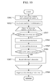
- Figure 10 is a flowchart showing the processing contents of the solid object determination means 45.
- step S501 the processing candidate information (PY1[i], PX1[i], and WD1[i]) selected by the processing candidate selection means 44 is read in.
- step S502 0 is substituted into the solid object number j for initialization. Thereafter, according to the processing candidate number that has been read in, the below described steps S503 to S507 are repeated.
- the process proceeds to S507, and the acquired processing candidate (relative distance PY1[i], lateral distance PX1[i], and width WD1[i]) is registered as it is as a solid object (relative distance PY2[j], lateral position PX2[j], and width WD2[j]), thereafter entering into the next repetitive processing.
- the processing after S504 will be successively performed.
- step S504 an image processing region on an image is set based on the processing candidate information and a camera geometry model. After the image processing region is set, the process proceeds to step S505, and image processing such as pattern matching that scans the inside of this region is executed to detect a solid object.
- the algorithm of image processing to be used at step S505 is the same as the second algorithm according to the above described step S304.
- step S506 a determination will be made on whether or not a solid object is detected, and when a solid object is detected ("YES" at step S506), the process proceeds to step S507 and the relative distance PY2[j], lateral position PX2[j], and width WD2[j] of the solid object are recorded and the solid object number j is added with 1.
- step S508 the solid object information of the recorded solid object (all the recorded relative distances PY2[j], lateral positions PX2[j], and widths WD2[j]) is outputted from the on-vehicle object detection device 101 to the outside thereby finishing the processing.
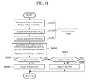
- Figure 11 is a flowchart showing the operation method of a pre-crash safety system.
- the solid object information (relative distance PY2[i], lateral position PX2[i], and width WD2[i]) calculated at the on-vehicle object detection device 100 or the on-vehicle object detection device 101 is read in.
- a time-to-collision TTC[i] of each detected object is calculated by using Expression (3).
- a relative speed VY[i] is determined by quasi-differentiating the relative distance PY[i] of the object.
- TTC i PY i ⁇ VY i
- a degree of risk DRECI[i] for each object is calculated.
- an example of the method of calculating the degree of risk DRECI[i] for the detected object X[i] by the on-vehicle object detection device 100 or the on-vehicle object detection device 101 will be described using Figure 7 .
- a perpendicular line is drawn to the center of a predicted travel path T obtained from an object X[i] by the above described method to determine a separation distance L[i] between an object X and a predicted travel path T.
- DRECI i H - L i / H Note that it is configured that the processing of steps S601 to S604 is performed in a loop process according to the number of detected objects.
- step S604 an object for which following Expression (5) holds is selected according to the degree of risk DRECI[i] calculated at step S603, and an object k of which the time-to-collision TTC[i] is minimum within the selected objects is selected.
- a predetermined value cDRECI# is a threshold value for determining whether or not the object will collide with the own vehicle 70.
- step S605 a determination is made on whether or not it is within the range in which braking is automatically controlled, according to the time-to-collision TTC[k] of the selected object k using the following Expression (6).
- step S607 a determination is made on whether or not it is within the range in which a warning is outputted according to the time-to-collision TTC[k] of the selected object k by using the following Expression (7).
- the object information (relative distance PY2[i], lateral position PX2[i], and width WD2[i]) obtained from the on-vehicle object detection device 100 or 101 which is the present invention is important parameters to be used for calculating a degree of risk DRECI[i] relating to the system operation such as automatic braking and warning.
- the present invention can reduce erroneous detection of non-solid objects near the own vehicle and thereby prevent erroneous operations of warning and automatic braking.
Applications Claiming Priority (2)
| Application Number | Priority Date | Filing Date | Title |
|---|---|---|---|
| JP2008127526A JP5283967B2 (ja) | 2008-05-14 | 2008-05-14 | 車載用物体検知装置 |
| PCT/JP2009/058806 WO2009139364A1 (ja) | 2008-05-14 | 2009-05-12 | 車載用物体検知装置 |
Publications (1)
| Publication Number | Publication Date |
|---|---|
| EP2288138A1 true EP2288138A1 (de) | 2011-02-23 |
Family
ID=41318731
Family Applications (1)
| Application Number | Title | Priority Date | Filing Date |
|---|---|---|---|
| EP09746571A Withdrawn EP2288138A1 (de) | 2008-05-14 | 2009-05-12 | Objekterkennungsvorrichtung für ein fahrzeug |
Country Status (3)
| Country | Link |
|---|---|
| EP (1) | EP2288138A1 (de) |
| JP (1) | JP5283967B2 (de) |
| WO (1) | WO2009139364A1 (de) |
Cited By (8)
| Publication number | Priority date | Publication date | Assignee | Title |
|---|---|---|---|---|
| WO2012156228A1 (de) * | 2011-05-19 | 2012-11-22 | Bayerische Motoren Werke Aktiengesellschaft | Verfahren und vorrichtung zum erkennen eines möglichen kollisionsobjektes |
| WO2013009697A1 (en) * | 2011-07-08 | 2013-01-17 | Bendix Commercial Vehicle Systems Llc | Image-based vehicle detection and distance measuring method and apparatus |
| DE102012009703A1 (de) | 2012-05-16 | 2013-11-21 | Volkswagen Ag | Verfahren und Vorrichtung zur Personenerkennung im Umfeld eines Kraftfahrzeugs |
| US8913786B2 (en) | 2010-12-02 | 2014-12-16 | Aisin Aw Co., Ltd. | Driving support system, driving support program, and driving support method |
| US9158738B2 (en) | 2010-07-09 | 2015-10-13 | Honda Motor Co., Ltd. | Apparatus for monitoring vicinity of a vehicle |
| KR20180069282A (ko) * | 2016-12-15 | 2018-06-25 | 현대자동차주식회사 | 자율주행을 위한 차선검출 방법. |
| US10525900B2 (en) | 2014-06-03 | 2020-01-07 | Honda Motor Co., Ltd. | Vehicle periphery monitoring device |
| EP3637131A3 (de) * | 2018-10-10 | 2020-06-17 | Sick Ag | Optoelektronischer sensor zur detektion von objekten und autonomes fahrzeug mit einem solchen sensor |
Families Citing this family (11)
| Publication number | Priority date | Publication date | Assignee | Title |
|---|---|---|---|---|
| JP5645103B2 (ja) * | 2010-05-17 | 2014-12-24 | いすゞ自動車株式会社 | 先行車検知装置 |
| KR101178508B1 (ko) * | 2010-07-19 | 2012-09-07 | 포항공과대학교 산학협력단 | 차량 충돌 경보 시스템 및 방법 |
| JP5690688B2 (ja) * | 2011-09-15 | 2015-03-25 | クラリオン株式会社 | 外界認識方法,装置,および車両システム |
| KR101355101B1 (ko) * | 2011-12-16 | 2014-01-27 | 아진산업(주) | 차량의 어라운드 뷰 모니터의 제어방법 |
| EP2654028B1 (de) * | 2012-04-20 | 2018-09-26 | Honda Research Institute Europe GmbH | Orientierungssensibles Verkehrskollisionswarnsystem |
| JP5786793B2 (ja) * | 2012-05-09 | 2015-09-30 | 株式会社デンソー | 車両検出装置 |
| EP2708913A1 (de) * | 2012-09-18 | 2014-03-19 | Sick Ag | Optoelektronischer Sensor und Verfahren zur Objekterfassung |
| JP6543117B2 (ja) * | 2015-07-07 | 2019-07-10 | 株式会社Subaru | 車両の運転支援装置 |
| JP6830656B2 (ja) | 2017-03-30 | 2021-02-17 | 株式会社エクォス・リサーチ | 対象物判定装置および対象物判定プログラム |
| JP7446605B2 (ja) | 2020-03-31 | 2024-03-11 | 株式会社ユピテル | システム、プログラム、学習済みモデル、学習モデルの生成方法および生成装置等 |
| JP2022169985A (ja) * | 2021-04-28 | 2022-11-10 | 日立Astemo株式会社 | 外界認識装置、および、外界認識システム |
Family Cites Families (4)
| Publication number | Priority date | Publication date | Assignee | Title |
|---|---|---|---|---|
| JP3367170B2 (ja) * | 1993-11-05 | 2003-01-14 | 株式会社豊田中央研究所 | 障害物検出装置 |
| JP3880837B2 (ja) * | 2001-11-02 | 2007-02-14 | 富士重工業株式会社 | 車外監視装置 |
| JP2007240314A (ja) * | 2006-03-08 | 2007-09-20 | Omron Corp | 物体検出装置 |
| JP5235295B2 (ja) | 2006-11-24 | 2013-07-10 | 三菱レイヨン株式会社 | 耐候性向上材を含む水性塗料 |
-
2008
- 2008-05-14 JP JP2008127526A patent/JP5283967B2/ja active Active
-
2009
- 2009-05-12 EP EP09746571A patent/EP2288138A1/de not_active Withdrawn
- 2009-05-12 WO PCT/JP2009/058806 patent/WO2009139364A1/ja active Application Filing
Non-Patent Citations (1)
| Title |
|---|
| See references of WO2009139364A1 * |
Cited By (11)
| Publication number | Priority date | Publication date | Assignee | Title |
|---|---|---|---|---|
| US9158738B2 (en) | 2010-07-09 | 2015-10-13 | Honda Motor Co., Ltd. | Apparatus for monitoring vicinity of a vehicle |
| US8913786B2 (en) | 2010-12-02 | 2014-12-16 | Aisin Aw Co., Ltd. | Driving support system, driving support program, and driving support method |
| WO2012156228A1 (de) * | 2011-05-19 | 2012-11-22 | Bayerische Motoren Werke Aktiengesellschaft | Verfahren und vorrichtung zum erkennen eines möglichen kollisionsobjektes |
| US9305221B2 (en) | 2011-05-19 | 2016-04-05 | Bayerische Motoren Werke Aktiengesellschaft | Method and apparatus for identifying a possible collision object |
| WO2013009697A1 (en) * | 2011-07-08 | 2013-01-17 | Bendix Commercial Vehicle Systems Llc | Image-based vehicle detection and distance measuring method and apparatus |
| US10081308B2 (en) | 2011-07-08 | 2018-09-25 | Bendix Commercial Vehicle Systems Llc | Image-based vehicle detection and distance measuring method and apparatus |
| DE102012009703A1 (de) | 2012-05-16 | 2013-11-21 | Volkswagen Ag | Verfahren und Vorrichtung zur Personenerkennung im Umfeld eines Kraftfahrzeugs |
| US10525900B2 (en) | 2014-06-03 | 2020-01-07 | Honda Motor Co., Ltd. | Vehicle periphery monitoring device |
| KR20180069282A (ko) * | 2016-12-15 | 2018-06-25 | 현대자동차주식회사 | 자율주행을 위한 차선검출 방법. |
| KR102453782B1 (ko) | 2016-12-15 | 2022-10-11 | 현대자동차주식회사 | 자율주행을 위한 차선검출 방법. |
| EP3637131A3 (de) * | 2018-10-10 | 2020-06-17 | Sick Ag | Optoelektronischer sensor zur detektion von objekten und autonomes fahrzeug mit einem solchen sensor |
Also Published As
| Publication number | Publication date |
|---|---|
| JP2009276200A (ja) | 2009-11-26 |
| WO2009139364A1 (ja) | 2009-11-19 |
| JP5283967B2 (ja) | 2013-09-04 |
Similar Documents
| Publication | Publication Date | Title |
|---|---|---|
| EP2288138A1 (de) | Objekterkennungsvorrichtung für ein fahrzeug | |
| US10246030B2 (en) | Object detection apparatus and driving assistance apparatus | |
| US10657393B2 (en) | Device and a method for distinguishing between traversable and nontraversable objects | |
| CN104573646B (zh) | 基于激光雷达和双目相机的车前行人检测方法及系统 | |
| US6687577B2 (en) | Simple classification scheme for vehicle/pole/pedestrian detection | |
| EP3032454B1 (de) | Verfahren und System zur adaptiven strahlenbasierten Szenenanalyse semantischer Verkehrsräume und mit solch einem System ausgestattetes Fahrzeug | |
| US9245188B2 (en) | Lane detection system and method | |
| JP5690688B2 (ja) | 外界認識方法,装置,および車両システム | |
| KR101188584B1 (ko) | 카메라와 레이저 스캐너를 이용한 차량 전방 물체 판별장치 | |
| US7542835B2 (en) | Vehicle image processing device | |
| US20120300078A1 (en) | Environment recognizing device for vehicle | |
| CN107991671A (zh) | 一种基于雷达数据和视频信号融合识别危险目标的方法 | |
| JP4892518B2 (ja) | 車両用外界認識装置、および、車両システム | |
| US8233663B2 (en) | Method for object formation | |
| JP5178276B2 (ja) | 画像認識装置 | |
| JP6313081B2 (ja) | 車載用画像処理装置およびそれを用いた車両システム | |
| KR102031503B1 (ko) | 다중 객체 검출 시스템 및 방법 | |
| JP6717240B2 (ja) | 物標検出装置 | |
| EP2224743B1 (de) | Verfahren zur überwachung einer fahrzeugumgebung, fahrzeug und programm zur überwachung einer fahrzeugumgebung | |
| CN105549013B (zh) | 用于汽车雷达成像的物体边界检测 | |
| US10482332B2 (en) | Pedestrian determining apparatus for determining whether an object is a pedestrian crossing ahead of an own vehicle | |
| CN102194102A (zh) | 对交通标志进行分类的方法和装置 | |
| JP5593217B2 (ja) | 車両用外界認識装置およびそれを用いた車両システム | |
| CN115240471A (zh) | 一种基于图像采集的智慧厂区避撞预警方法和系统 | |
| EP3023907A1 (de) | Gradientendetektion auf Grundlage eines Bildes mit veränderter Perspektive |
Legal Events
| Date | Code | Title | Description |
|---|---|---|---|
| PUAI | Public reference made under article 153(3) epc to a published international application that has entered the european phase |
Free format text: ORIGINAL CODE: 0009012 |
|
| 17P | Request for examination filed |
Effective date: 20101214 |
|
| AK | Designated contracting states |
Kind code of ref document: A1 Designated state(s): AT BE BG CH CY CZ DE DK EE ES FI FR GB GR HR HU IE IS IT LI LT LU LV MC MK MT NL NO PL PT RO SE SI SK TR |
|
| AX | Request for extension of the european patent |
Extension state: AL BA RS |
|
| DAX | Request for extension of the european patent (deleted) | ||
| STAA | Information on the status of an ep patent application or granted ep patent |
Free format text: STATUS: THE APPLICATION IS DEEMED TO BE WITHDRAWN |
|
| 18D | Application deemed to be withdrawn |
Effective date: 20151201 |