EP2287367B1 - Dispositif et procédé de fabrication de monocristaux - Google Patents
Dispositif et procédé de fabrication de monocristaux Download PDFInfo
- Publication number
- EP2287367B1 EP2287367B1 EP09746653.6A EP09746653A EP2287367B1 EP 2287367 B1 EP2287367 B1 EP 2287367B1 EP 09746653 A EP09746653 A EP 09746653A EP 2287367 B1 EP2287367 B1 EP 2287367B1
- Authority
- EP
- European Patent Office
- Prior art keywords
- single crystal
- silicon carbide
- raw material
- crystal growth
- guide members
- Prior art date
- Legal status (The legal status is an assumption and is not a legal conclusion. Google has not performed a legal analysis and makes no representation as to the accuracy of the status listed.)
- Not-in-force
Links
Images


Classifications
-
- C—CHEMISTRY; METALLURGY
- C30—CRYSTAL GROWTH
- C30B—SINGLE-CRYSTAL GROWTH; UNIDIRECTIONAL SOLIDIFICATION OF EUTECTIC MATERIAL OR UNIDIRECTIONAL DEMIXING OF EUTECTOID MATERIAL; REFINING BY ZONE-MELTING OF MATERIAL; PRODUCTION OF A HOMOGENEOUS POLYCRYSTALLINE MATERIAL WITH DEFINED STRUCTURE; SINGLE CRYSTALS OR HOMOGENEOUS POLYCRYSTALLINE MATERIAL WITH DEFINED STRUCTURE; AFTER-TREATMENT OF SINGLE CRYSTALS OR A HOMOGENEOUS POLYCRYSTALLINE MATERIAL WITH DEFINED STRUCTURE; APPARATUS THEREFOR
- C30B23/00—Single-crystal growth by condensing evaporated or sublimed materials
- C30B23/002—Controlling or regulating
- C30B23/005—Controlling or regulating flux or flow of depositing species or vapour
-
- C—CHEMISTRY; METALLURGY
- C30—CRYSTAL GROWTH
- C30B—SINGLE-CRYSTAL GROWTH; UNIDIRECTIONAL SOLIDIFICATION OF EUTECTIC MATERIAL OR UNIDIRECTIONAL DEMIXING OF EUTECTOID MATERIAL; REFINING BY ZONE-MELTING OF MATERIAL; PRODUCTION OF A HOMOGENEOUS POLYCRYSTALLINE MATERIAL WITH DEFINED STRUCTURE; SINGLE CRYSTALS OR HOMOGENEOUS POLYCRYSTALLINE MATERIAL WITH DEFINED STRUCTURE; AFTER-TREATMENT OF SINGLE CRYSTALS OR A HOMOGENEOUS POLYCRYSTALLINE MATERIAL WITH DEFINED STRUCTURE; APPARATUS THEREFOR
- C30B29/00—Single crystals or homogeneous polycrystalline material with defined structure characterised by the material or by their shape
- C30B29/10—Inorganic compounds or compositions
- C30B29/36—Carbides
-
- C—CHEMISTRY; METALLURGY
- C30—CRYSTAL GROWTH
- C30B—SINGLE-CRYSTAL GROWTH; UNIDIRECTIONAL SOLIDIFICATION OF EUTECTIC MATERIAL OR UNIDIRECTIONAL DEMIXING OF EUTECTOID MATERIAL; REFINING BY ZONE-MELTING OF MATERIAL; PRODUCTION OF A HOMOGENEOUS POLYCRYSTALLINE MATERIAL WITH DEFINED STRUCTURE; SINGLE CRYSTALS OR HOMOGENEOUS POLYCRYSTALLINE MATERIAL WITH DEFINED STRUCTURE; AFTER-TREATMENT OF SINGLE CRYSTALS OR A HOMOGENEOUS POLYCRYSTALLINE MATERIAL WITH DEFINED STRUCTURE; APPARATUS THEREFOR
- C30B29/00—Single crystals or homogeneous polycrystalline material with defined structure characterised by the material or by their shape
- C30B29/10—Inorganic compounds or compositions
- C30B29/40—AIIIBV compounds wherein A is B, Al, Ga, In or Tl and B is N, P, As, Sb or Bi
- C30B29/403—AIII-nitrides
- C30B29/406—Gallium nitride
Definitions
- the present invention relates to a single crystal manufacturing device and a manufacturing method.
- Patent Documents 1 and 2 disclose methods for manufacturing a silicon carbide single crystal.
- one guide member is provided inside a crucible. This guide member guides a sublimed gas of a silicon carbide raw material to a silicon carbide seed crystal. Then, a silicon carbide single crystal grows on a surface of the guide member (specifically, a surface thereof facing the silicon carbide raw material).
- the silicon carbide single crystal growing on an inside surface of the guide member faces the silicon carbide raw material. Accordingly, both the silicon carbide raw material and the silicon carbide single crystal are susceptible to the effect of heat radiation from each other.
- the silicon carbide single crystal is likely to absorb heat from the silicon carbide raw material. Therefore, there arises a problem of a difficulty in controlling the temperature of the silicon carbide raw material.
- a center portion of a silicon carbide single crystal (a part extending vertically downward from the silicon carbide seed crystal) will be used as a product. Accordingly, in order to prevent a polycrystal from entering this center portion, a guide member needs to be made wide in the lateral direction. However, when the guide member is made wider in the lateral direction, a silicon carbide single crystal ends up growing along the guide member. Therefore, there arises a problem that the center portion to be used as a product is smaller than a portion which will not be used as a product.
- the present invention has been carried out to solve the problems described above, and an object thereof is to provide a single crystal manufacturing method and manufacturing device which are capable of improving the quality of a single crystal and facilitating the growth of a center portion of the single crystal by making the temperature control of a raw material for single crystal growth easier than in the past.
- the gist thereof is a single crystal manufacturing device, comprising: a container member configured to house a raw material for single crystal growth and a seed crystal for single crystal growth in such a manner that the raw material for single crystal growth and the seed crystal for single crystal growth face each other, the raw material for single crystal growth being used as a single crystal raw material, a sublimed gas produced by sublimation of the raw material for single crystal growth recrystallizing on the seed crystal for single crystal growth, and a plurality of guide members provided inside the container member, wherein the guide members each have an opening portion formed therein at a position corresponding to the seed crystal for single crystal growth, and are provided at intervals between the raw material for single crystal growth and the seed crystal for single crystal growth.
- the gist thereof is a single crystal manufacturing method, comprising the steps of housing a raw material for single crystal growth and a seed crystal for single crystal growth at respective positions facing each other inside a container member, and arranging guide members, which each have an opening portion formed therein at a position corresponding to the seed crystal for single crystal growth, at intervals between the raw material for single crystal growth and the seed crystal for single crystal growth, and subliming the raw material for single crystal growth, guiding a sublimed gas of the raw material for single crystal growth by the plurality of guide members to the seed crystal for single crystal growth, and growing a single crystal on surfaces of the plurality of guide members.
- the multiple guide members are provided at intervals. Accordingly, a single crystal grown between the guide members is not exposed to the raw material for single crystal growth.
- a conventional manufacturing method includes only one guide member. Accordingly, the area of a single crystal exposed to the raw material for single crystal growth (hereinafter, also referred to as an "exposure area of single crystal") becomes larger as the single crystal grows.
- the exposure area of single crystal can be made smaller than that in the conventional manufacturing method. Accordingly, the effects of heat radiation on the raw material for single crystal growth and the single crystal from each other can be smaller.
- the temperature control on the raw material for single crystal growth can be performed more easily than in the past.
- the temperature of the raw material for single crystal growth can be easily maintained high. Further, with the multiple guide members provided at intervals, the heat insulating effect inside the container member is improved. In other words, the inside of the container member can be easily maintained at a target temperature.
- the single crystal manufacturing device and manufacturing method according to the present invention once reaching the next guide member after growing on a surface of a first guide member, a single crystal hardly grows on the surface of the first guide member but grows on a surface of the next guide member. Accordingly, the contact area between the single crystal and each of the guide members can be suppressed to a certain value or below. In addition, this value can be made smaller by narrowing the intervals between the guide members.
- the contact area between the single crystal and the guide member becomes larger as the single crystal grows.
- the contact area between the single crystal and each of the guide members can be made smaller compare to that by the conventional manufacturing method. Accordingly, it is possible to prevent growth in a portion other than the center portion of the single crystal as well as to allow the center portion of the single crystal, which is to be used as a product, to grow large.
- the effect of the heat stress generated between the single crystal and each of the guide members can be made smaller; therefore, the possibility of a crack occurring in the single crystal can be reduced.
- the contact area between the single crystal and each of the guide members can be made smaller than in the conventional manufacturing method. Accordingly, the growth of the center portion to be used as a product can be facilitated.
- the temperature control on the raw material for single crystal growth is easier than in the conventional manufacturing method. Accordingly, the quality of single crystal can be improved. Further, the growth of a center portion of a single crystal can be facilitated.
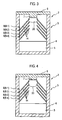
- a silicon carbide single crystal manufacturing device 1 as an embodiment of the present invention includes, as shown in Fig. 1 , a crucible 2, a silica pipe 9, a support rod 10, a first heating coil 11, a second heating coil 12, and an interference preventing coil 13.
- the crucible 2 includes a container member 3 and multiple guide members 8.
- the container member 3 includes a crucible main body 4 and a lid 6.
- the crucible main body 4 is a cylindrical container made of graphite.
- the crucible main body 4 has an opening.
- the crucible main body 4 can house a silicon carbide raw material 5 which is a silicon carbide powder therein through the opening.
- the lid 6 is made of graphite.
- the lid 6 has a disc shape.
- One surface of the lid 6 has a protruding shape.
- a silicon carbide seed crystal 7 is attached on a tip of the protruding portion.
- the lid 6 can close the opening of the crucible main body 4 while the silicon carbide seed crystal 7 and the silicon carbide raw material 5 face each other.
- the seed crystal 7 has a disc shape.
- the guide members 8 are made of graphite. Multiple guide members 8 are provided at intervals inside the crucible main body 4. Each of the guide members 8 has a shape obtained by cutting off a top end portion of a surface of a cone along a plane perpendicular to a perpendicular line extending from the apex of the cone to the bottom surface of the cone. Accordingly, a circular opening is formed at an upper end portion of each of the guide members 8. The diameter of the upper end portion of each of the guide members 8 is the same as the diameter of the seed crystal 7. Further, all the guide members 8 have the same shape. Accordingly, when the multiple guide members 8 are arranged inside the crucible main body 4, a columnar space is formed with the openings at the upper end portions of the guide members 8. In this space, the silicon carbide raw material 5 and the seed crystal 7 face each other.
- a sublimed gas of the silicon carbide raw material 5 is guided by an inner surface (a surface facing the silicon carbide raw material 5) of each of the guide members 8 to the silicon carbide seed crystal 7. Further, a silicon carbide single crystal grows on the inner surfaces 14 of the guide members 8.
- the guide members 8 are also referred to as, from the top, a guide member 8-1, a guide member 8-2, a guide member 8-3, and a guide member 8-4.
- the silica pipe 9 houses therein the crucible main body 2 and the lid 5. Inside the silica pipe 9, an argon gas atmosphere is achieved after the crucible 2 is introduced therein.
- the support rod 10 is provided inside the silica pipe 9. The support rod 10 supports the crucible main body 2 inside the silica pipe 9.
- the first heating coil 11, the second heating coil 12, and the interference preventing coil 13 are apart from each other at certain intervals. There are certain gaps between the silica pipe 9 and each of the first heating coil 11, the second heating coil 12 and the interference preventing coil 13. The first heating coil 11, the second heating coil 12 and the interference preventing coil 13 are wound around an external surface of the silica pipe 9.
- the second heating coil 12 is arranged at a position which is outside of the silica pipe 9 and corresponds to the vicinity of the silica carbide raw material 5, with the crucible 2 having introduced into the silica pipe 9.
- the second heating coil 12 is arranged in order to adjust the temperature of the silicon carbide raw material 5.
- the first heating coil 11 is arranged at a position which is outside of the silica pipe 9 and corresponds to the vicinity of the seed crystal 7, with the lid 6 having introduced into the silica pipe 9.
- the first heating coil 11 is arranged in order to adjust the temperature of the seed crystal 7.
- the interference preventing coil 13 is provided between the first heating coil 11 and the second heating coil 12.
- the interference preventing coil 13 is configured to prevent the first heating coil 11 and the second heating coil 12 from interfering each other.
- the interference preventing coil 13 is configured, when an electric current goes through one of the first heating coil 11 and the second heating coil 12, to reduce the effect of a magnetic field generated from the one heating coil on the other heating coil.
- Step S1 the silicon carbide raw material 5 which is a silicon carbide powder is supplied into the crucible main body 4.
- Step S2 the seed crystal 7 is attached to the lid 6.
- This lid 6 closes the opening of the crucible main body 4 with the seed crystal 7 facing the silicon carbide raw material 5.
- Step S3 the crucible 2 is introduced into the silica pipe 9, and fixed with the support rod 10. This state is illustrated in Fig. 1 . Further, the inner pressure of the silica pipe 9 is set to 10 Torr, and an argon gas atmosphere is achieved.
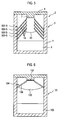
- Step S4 the first heating coil 11 and the second heating coil 12 are heated to achieve the temperature of the seed crystal 7 of 2300 degrees (the temperature for recrystallization of silicon carbide) and the temperature of the crucible main body 4 of 2400 degrees (the temperature for sublimation of the silicon carbide raw material 5). This state is maintained for 50 hours. This allows sublimation of the silicon carbide raw material 5, and a sublimed gas is guided by the inner surfaces 14 of the guide members 8 to the seed crystal 7. Then, a silicon carbide single crystal 20 is recrystallized (that is, grows) on the surface of the seed crystal 7 as shown in Figs. 3 and 4 .
- description will be given of how the silicon carbide single crystal 20 grows by referring to Figs. 3 to 5 .
- the silicon carbide single crystal 20 grows in this upper end portion. Once having reached the inner surface 14 of the guide member 8-1, the silicon carbide single crystal 20 grows on this inner surface 14. Thereafter, once having reached an upper end portion of the guide member 8-2, the silicon carbide single crystal 20 hardly grows on the inner surface 14 of the guide member 8-1, but grows in the upper end portion of the guide member 8-2, as shown in Fig. 4 . Once having reached the inner surface 14 of the guide member 8-2, the silicon carbide single crystal 20 grows on this inner surface 14. Thereafter, the silicon carbide single crystal 20 grows in a similar fashion. At the end, as shown in Fig. 5 , the silicon carbide single crystal 20 grows on the inner surface 14 of the guide member 8-4. When the silicon carbide single crystal 20 has grown to a predetermined size on the inner surface 14 of the guide member 8-4, the process of Step S4 ends.
- the contact area between the silicon carbide single crystal 20 and the inner surface 14 of the guide member 8-4 is smaller than the contact area between the guide member and the inner surface upon the completion of the growth of a silicon carbide single crystal in a conventional manufacturing method.
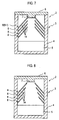
- Fig. 6 shows a silicon carbide single crystal 105 grown in a conventional manufacturing method.
- the conventional manufacturing method will be described briefly.
- a silicon carbide seed crystal 102 and a silicon carbide raw material 103 are arranged at respective positions facing each other inside a container member 101.
- the container member 101, the seed crystal 102 and the silicon carbide raw material 103 are those equivalent to the container member 3, the seed crystal 7 and the silicon carbide raw material 5, respectively.
- the guide member 104 is made of graphite.
- the guide member 104 has a shape obtained by cutting off a top end portion of a surface of a cone along a plane perpendicular to a perpendicular line extending from the apex of the cone to the bottom of the cone. Accordingly, a circular opening is formed at the upper end portion of the guide member 104.
- the shape of the guide member 104 and the shape of the guide member 8 are similar, the angle between the inner surface 106 and a perpendicular line of the surface of the seed crystal 102 is larger than the angle between the inner surface 14 of the guide member 8 and a perpendicular line of the surface of the seed crystal 7.
- the guide member 104 has a steeper angle than the guide member 8.
- Step S3 and Step S4 are performed. This allows recrystallization of a silicon carbide single crystal 105 on the inner surface 106 of the guide member 104.
- the manufacturing method according to the present embodiment can provide the following advantageous effect compared to the conventional manufacturing method.
- the manufacturing apparatus has the multiple guide members 8 at predetermined intervals from each other inside the crucible main body 4. Accordingly, a silicon carbide single crystal grown between the guide members 8 is not exposed to the silicon carbide raw material 5. Specifically, the area of the silicon carbide single crystal 20 exposed to the silicon carbide raw material 5 (hereinafter, also referred to as an "exposure area of the silicon carbide single crystal 20") is suppressed to an area comparable in size to each of the opening surfaces at the upper end portions of the guide members 8 during the growth of the silicon carbide single crystal 20.
- the conventional manufacturing apparatus is provided with only one guide member 104. Accordingly, the exposure area of the silicon carbide single crystal 105 is comparable in size to the area of the opening surface at the upper portion of the guide member 104 when the silicon carbide single crystal 105 has reached the inner surface 106 of the guide member 104. Then, the exposure area of the silicon carbide single crystal 105 becomes larger as the silicon carbide single crystal 105 grows.
- the exposure surface of the silicon carbide single crystal 20 during the growth of the silicon carbide single crystal 20 is smaller than the exposure area of the silicon carbide single crystal 105 during the growth of the silicon carbide single crystal 105.
- the manufacturing method according the present embodiment can make the exposure area of the silicon carbide single crystal 20 smaller than the exposure area of the silicon carbide single crystal 105. Therefore, compared to the conventional manufacturing method, the area in which the silicon carbide single crystal and the silicon carbide raw material face each other can be smaller. Thus, the effect of heat radiation on the silicon carbide single crystal and the silicon carbide raw material from each other can be smaller.
- the silicon carbide single crystal 20 grows on and along the inner surface 14 of a first guide member 8 (the guide member 8-1, for example), reaches an upper end portion of the next guide member 8 (the guide member 8-2, for example), and then grows along the inner surface 14 of the guide member 8-2.
- the silicon carbide single crystal 20 hardly grows on and along the inner surface 14 of the first guide member 8, but grows inside the columnar space. Accordingly, the contact area between the silicon carbide single crystal 20 and each of the guide members 8 is suppressed to a certain value or below. This value can be made smaller by narrowing the intervals among the guide members 8.
- the manufacturing method according to the present embodiment can make the contact area between the silicon carbide single crystal 20 and each of the guide members 8 smaller than that in the conventional manufacturing method. This allows the effect of thermal stress generated between the silicon carbide single crystal 20 and each of the guide members 8 to be smaller. Thus, the possibility of a crack occurring in the silicon carbide single crystal 20 can be reduced.
- the conventional manufacturing method can make the contact area between the silicon carbide single crystal and the guide member smaller, thereby preventing a lowering in the temperature of the guide member. This can make the angle between the inner surface 14 of the guide member 8 and a horizontal surface smaller than the angle between the inner surface 106 of the guide member 104 and a horizontal surface. Accordingly, the manufacturing method according to the present embodiment allows a center portion, which is to be used as a product, to grow larger than that in the conventional manufacturing method.
- the manufacturing method according to the present embodiment allows easier control on the temperature of the silicon carbide raw material 5 than that in the conventional manufacturing method, improving the quality of the silicon carbide single crystal 20. Therefore, a center portion of the silicon carbide single crystal 20 can grow larger.
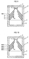
- Figs. 7 to 12 show modification examples of the crucible 2.
- the guide member 8-1 is provided to the lid 6.
- An upper end portion of the guide member 8-1 is closely attached to a side surface of a protruding portion of the lid 6.
- the diameter of the upper end portion of the guide member 8 is larger for the guide member 8 located lower. Accordingly, a conical shape is formed by connecting upper end portions of the guide members 8.
- the diameter of the upper end portion of the guide member 8 is larger for the guide member 8 located lower. Accordingly, a conical shape is formed by connecting upper end portions of the guide members 8. In addition, the diameter of the upper end portion of the guide member 8-1 is smaller than the diameter of the seed crystal 7.
- the diameter of the upper end portion of the guide member 8-1 and the diameter of the upper end portion of the guide member 8-2 are the same, and the diameter of the upper end portion of the guide member 8-3 and the diameter of the upper end portion of the guide member 8-4 are the same.
- the diameter of the upper end portion of the guide member 8-3 is larger than the diameter of the upper end portion of the guide member 8-1.
- the diameter of the upper end portion of the guide member 8-1 is smaller than the diameter of the seed crystal.
- each of the guide members 8 has a flat plate shape.
- Each of the guide members 8 is provided with a circular opening portion formed at a position corresponding to the seed crystal 7.
- the diameter of the opening portion is the same as the diameter of the seed crystal 7.
- a columnar space is formed by connecting these opening portions.
- each of the guide members 8 has a flat plate shape.
- Each of the guide members 8 is provided with a circular opening portion formed at a position corresponding to the seed crystal 7.
- the diameter of the opening portion disposed at the uppermost stage is same as the diameter of the seed crystal 7.
- the diameter of the opening portion is larger for the guide member 8 provided at a lower position. Accordingly, a conical space is formed by connecting these holes.
- the silicon carbide raw material 5 may be changed to a powder of GaN or AlN, and the seed crystal 7 may be changed to a seed crystal of GaN or AlN. According to this modification example, the above-described effects can be obtained, and further, a single crystal of GaN or AlN can be grown.
- the single crystal manufacturing device and manufacturing method according to the present invention allow easier control on the temperature of a raw material for single crystal growth than in the past. Therefore, the quality of a single crystal can be improved. Further, the growth of a center portion of a single crystal can be facilitated. Thus, the single crystal manufacturing device and manufacturing method according to the present invention is useful in the field of single crystal manufacturing.
Claims (8)
- Dispositif de fabrication de monocristaux (1), comprenant :un élément formant conteneur (3) configuré pour accueillir une matière première pour croissance monocristalline (5) et un cristal germe pour croissance monocristalline (7) de telle manière que la matière première pour croissance monocristalline (5) et le cristal germe pour croissance monocristalline (7) se font face l'un l'autre, la matière première pour croissance monocristalline (5) étant utilisée en tant que matière première de monocristal, un gaz sublimé produit par sublimation de la matière première pour croissance monocristalline (5) se recristallisant sur le cristal germe pour croissance monocristalline (7), etcaractérisé par :une pluralité d'éléments de guidage (8) fournis à l'intérieur de l'élément formant conteneur (3), dans lequel les éléments de guidage (8) présentent respectivement une partie ouverture formée en leur sein au niveau d'une position correspondant au cristal germe pour croissance monocristalline (7), et sont fournis à des intervalles entre la matière première pour croissance monocristalline (5) et le cristal germe pour croissance monocristalline (7).
- Dispositif de fabrication de monocristaux selon la revendication 1, dans lequel
un intérieur de l'élément formant conteneur (3) présente une forme de colonne,
les éléments de guidage (8) présentent respectivement une forme de cône,
un diamètre d'une surface basale du cône est essentiellement identique à un diamètre intérieur de l'élément formant conteneur (3), et
une partie ouverture est formée au niveau d'une partie extrémité supérieure de chacun des éléments de guidage (8), la partie ouverture étant formée par découpe d'une partie extrémité supérieure d'une surface du cône le long d'un plan perpendiculaire à une ligne perpendiculaire s'étendant à partir d'un sommet du cône vers la surface basale du cône. - Dispositif de fabrication de monocristaux selon la revendication 2, dans lequel
un diamètre de la partie ouverture formée dans chaque élément parmi la pluralité d'éléments de guidage (8) est augmenté en direction d'une position inférieure dans l'élément formant conteneur (3). - Dispositif de fabrication de monocristaux selon la revendication 1, dans lequel
un intérieur de l'élément formant conteneur (3) présente une forme de colonne,
les éléments de guidage (8) présentent respectivement une forme de plaque plate, et
une partie ouverture est formée au niveau de la position correspondant au cristal germe pour croissance monocristalline (7) dans chaque élément parmi la pluralité d'éléments de guidage (8). - Dispositif de fabrication de monocristaux selon la revendication 4, dans lequel
un diamètre de la partie ouverture formée dans chaque élément parmi la pluralité d'éléments de guidage (8) est augmenté en direction d'une position inférieure dans l'élément formant conteneur (3). - Dispositif de fabrication de monocristaux selon la revendication 1, dans lequel
un monocristal est formé par recristallisation d'un gaz sublimé, qui est produit par sublimation de la matière première pour croissance monocristalline (5), sur une surface du cristal germe pour croissance monocristalline (7), et
le monocristal est sélectionné parmi le groupe constitué de SiC, GaN et AIN. - Procédé de fabrication de monocristaux,
caractérisé par les étapes consistant à :accueillir une matière première pour croissance monocristalline (5) et un cristal germe pour croissance monocristalline (7) au niveau de positions respectives se faisant face l'une l'autre à l'intérieur d'un élément formant conteneur (3), et agencer une pluralité d'éléments de guidage (8) qui présentent respectivement une partie ouverture formée en leur sein au niveau d'une position correspondant au cristal germe pour croissance monocristalline (7), à des intervalles entre la matière première pour croissance monocristalline (5) et le cristal germe pour croissance monocristalline (7), etsublimer la matière première pour croissance monocristalline (5), guider un gaz sublimé de la matière première pour croissance monocristalline (5) grâce à la pluralité d'éléments de guidage (8) vers le cristal germe pour croissance monocristalline (7) et faire croître un monocristal sur des surfaces de la pluralité d'éléments de guidage (8). - Procédé de fabrication de monocristaux selon la revendication 7, dans lequel le monocristal est sélectionné parmi le groupe constitué de SiC, GaN et AIN.
Applications Claiming Priority (2)
| Application Number | Priority Date | Filing Date | Title |
|---|---|---|---|
| JP2008129187A JP5271601B2 (ja) | 2008-05-16 | 2008-05-16 | 単結晶の製造装置及び製造方法 |
| PCT/JP2009/059013 WO2009139447A1 (fr) | 2008-05-16 | 2009-05-14 | Dispositif et procédé de fabrication de monocristaux |
Publications (3)
| Publication Number | Publication Date |
|---|---|
| EP2287367A1 EP2287367A1 (fr) | 2011-02-23 |
| EP2287367A4 EP2287367A4 (fr) | 2011-09-14 |
| EP2287367B1 true EP2287367B1 (fr) | 2016-01-13 |
Family
ID=41318808
Family Applications (1)
| Application Number | Title | Priority Date | Filing Date |
|---|---|---|---|
| EP09746653.6A Not-in-force EP2287367B1 (fr) | 2008-05-16 | 2009-05-14 | Dispositif et procédé de fabrication de monocristaux |
Country Status (4)
| Country | Link |
|---|---|
| US (1) | US20110107961A1 (fr) |
| EP (1) | EP2287367B1 (fr) |
| JP (1) | JP5271601B2 (fr) |
| WO (1) | WO2009139447A1 (fr) |
Cited By (1)
| Publication number | Priority date | Publication date | Assignee | Title |
|---|---|---|---|---|
| US9525032B2 (en) | 2005-12-02 | 2016-12-20 | Crystal Is, Inc. | Doped aluminum nitride crystals and methods of making them |
Families Citing this family (16)
| Publication number | Priority date | Publication date | Assignee | Title |
|---|---|---|---|---|
| US7638346B2 (en) | 2001-12-24 | 2009-12-29 | Crystal Is, Inc. | Nitride semiconductor heterostructures and related methods |
| US8545629B2 (en) | 2001-12-24 | 2013-10-01 | Crystal Is, Inc. | Method and apparatus for producing large, single-crystals of aluminum nitride |
| US9034103B2 (en) | 2006-03-30 | 2015-05-19 | Crystal Is, Inc. | Aluminum nitride bulk crystals having high transparency to ultraviolet light and methods of forming them |
| US9771666B2 (en) | 2007-01-17 | 2017-09-26 | Crystal Is, Inc. | Defect reduction in seeded aluminum nitride crystal growth |
| US8323406B2 (en) | 2007-01-17 | 2012-12-04 | Crystal Is, Inc. | Defect reduction in seeded aluminum nitride crystal growth |
| US8080833B2 (en) | 2007-01-26 | 2011-12-20 | Crystal Is, Inc. | Thick pseudomorphic nitride epitaxial layers |
| JP4992965B2 (ja) * | 2009-12-25 | 2012-08-08 | 株式会社デンソー | 炭化珪素単結晶の製造装置 |
| JP5666150B2 (ja) * | 2010-02-26 | 2015-02-12 | 昭和電工株式会社 | 遮蔽部材及びそれを備えた単結晶成長装置 |
| JP5806734B2 (ja) | 2010-06-30 | 2015-11-10 | クリスタル アイエス, インコーポレーテッドCrystal Is, Inc. | 熱勾配制御による窒化アルミニウム大単結晶成長 |
| KR20120131016A (ko) * | 2011-05-24 | 2012-12-04 | 엘지이노텍 주식회사 | 잉곳 제조 장치 |
| US8962359B2 (en) | 2011-07-19 | 2015-02-24 | Crystal Is, Inc. | Photon extraction from nitride ultraviolet light-emitting devices |
| CN108511567A (zh) | 2013-03-15 | 2018-09-07 | 晶体公司 | 与赝配电子和光电器件的平面接触 |
| DE102018129492B4 (de) * | 2018-11-22 | 2022-04-28 | Ebner Industrieofenbau Gmbh | Vorrichtung und Verfahren zum Züchten von Kristallen |
| JP7400450B2 (ja) | 2019-12-25 | 2023-12-19 | 株式会社レゾナック | SiC単結晶製造装置およびSiC単結晶の製造方法 |
| CN112746326A (zh) * | 2020-12-25 | 2021-05-04 | 哈尔滨化兴软控科技有限公司 | 一种提高AlN单晶质量的装置和方法 |
| CN114059156B (zh) * | 2021-11-30 | 2023-03-28 | 江苏集芯半导体硅材料研究院有限公司 | 碳化硅晶体生长装置 |
Family Cites Families (7)
| Publication number | Priority date | Publication date | Assignee | Title |
|---|---|---|---|---|
| WO2001091167A1 (fr) * | 2000-05-25 | 2001-11-29 | Toppan Printing Co., Ltd. | Substrat pour masque de transfert, masque de transfert et son procede de fabrication |
| JP3961750B2 (ja) * | 2000-08-21 | 2007-08-22 | 独立行政法人産業技術総合研究所 | 単結晶の成長装置および成長方法 |
| JP2004223663A (ja) | 2003-01-24 | 2004-08-12 | Doshisha | インピーダンス制御装置、およびインピーダンス制御プログラム |
| JP4102876B2 (ja) * | 2003-01-27 | 2008-06-18 | 独立行政法人産業技術総合研究所 | 単結晶成長装置 |
| US7212805B2 (en) * | 2003-05-07 | 2007-05-01 | M-Stack Limited | Apparatus and method of handling simultaneous universal terrestrial radio access network radio resource control procedures which change the security configuration in a universal mobile telecommunications system user equipment |
| US7387680B2 (en) * | 2005-05-13 | 2008-06-17 | Cree, Inc. | Method and apparatus for the production of silicon carbide crystals |
| JP4858106B2 (ja) | 2006-11-17 | 2012-01-18 | 凸版印刷株式会社 | カラーフィルタの欠陥検査方法 |
-
2008
- 2008-05-16 JP JP2008129187A patent/JP5271601B2/ja not_active Expired - Fee Related
-
2009
- 2009-05-14 EP EP09746653.6A patent/EP2287367B1/fr not_active Not-in-force
- 2009-05-14 US US12/992,785 patent/US20110107961A1/en not_active Abandoned
- 2009-05-14 WO PCT/JP2009/059013 patent/WO2009139447A1/fr active Application Filing
Cited By (1)
| Publication number | Priority date | Publication date | Assignee | Title |
|---|---|---|---|---|
| US9525032B2 (en) | 2005-12-02 | 2016-12-20 | Crystal Is, Inc. | Doped aluminum nitride crystals and methods of making them |
Also Published As
| Publication number | Publication date |
|---|---|
| WO2009139447A1 (fr) | 2009-11-19 |
| US20110107961A1 (en) | 2011-05-12 |
| EP2287367A1 (fr) | 2011-02-23 |
| JP5271601B2 (ja) | 2013-08-21 |
| JP2009274930A (ja) | 2009-11-26 |
| EP2287367A4 (fr) | 2011-09-14 |
Similar Documents
| Publication | Publication Date | Title |
|---|---|---|
| EP2287367B1 (fr) | Dispositif et procédé de fabrication de monocristaux | |
| JP3961750B2 (ja) | 単結晶の成長装置および成長方法 | |
| JP5304600B2 (ja) | SiC単結晶の製造装置及び製造方法 | |
| US10988857B2 (en) | SiC single crystal growth apparatus containing movable heat-insulating material and growth method of SiC single crystal using the same | |
| US20120060749A1 (en) | Apparatus of manufacturing silicon carbide single crystal and method of manufacturing silicon carbide single crystal | |
| JP6338439B2 (ja) | 炭化珪素単結晶インゴットの製造方法 | |
| JP5012655B2 (ja) | 単結晶成長装置 | |
| JP4459211B2 (ja) | 単結晶の成長装置および成長方法 | |
| JP2017065969A (ja) | 炭化珪素単結晶インゴット製造用の黒鉛坩堝及び炭化珪素単結晶インゴットの製造方法 | |
| JP5087489B2 (ja) | 炭化珪素単結晶の製造装置及び炭化珪素単結晶の製造方法 | |
| JP2010076990A (ja) | 炭化珪素単結晶の製造装置及び炭化珪素単結晶の製造方法 | |
| KR20130083653A (ko) | 단결정 성장 장치 | |
| JP2007308355A (ja) | 炭化ケイ素単結晶の製造装置及びその製造方法 | |
| KR102202447B1 (ko) | 탄화규소 단결정 성장장치 | |
| KR101530272B1 (ko) | 잉곳성장장치 및 잉곳성장방법 | |
| US8691013B2 (en) | Feed tool for shielding a portion of a crystal puller | |
| US11453959B2 (en) | Crystal growth apparatus including heater with multiple regions and crystal growth method therefor | |
| US20230243063A1 (en) | SiC CRYSTAL MANUFACTURING METHOD | |
| WO2022045291A1 (fr) | Procédé de fabrication de polycristal de sic | |
| KR20130083654A (ko) | 단결정 성장 장치 | |
| KR101649539B1 (ko) | 역 승화 단결정 성장장치 | |
| JP2022064015A (ja) | 炭化珪素単結晶の製造方法及び製造装置並びに炭化珪素単結晶インゴット | |
| JP2013133273A (ja) | 単結晶製造装置および単結晶の製造方法 | |
| JP5536501B2 (ja) | 炭化ケイ素単結晶の製造装置 | |
| JP2011184209A (ja) | 単結晶製造装置、種結晶固定方法及び炭化珪素単結晶の製造方法 |
Legal Events
| Date | Code | Title | Description |
|---|---|---|---|
| PUAI | Public reference made under article 153(3) epc to a published international application that has entered the european phase |
Free format text: ORIGINAL CODE: 0009012 |
|
| 17P | Request for examination filed |
Effective date: 20101206 |
|
| AK | Designated contracting states |
Kind code of ref document: A1 Designated state(s): AT BE BG CH CY CZ DE DK EE ES FI FR GB GR HR HU IE IS IT LI LT LU LV MC MK MT NL NO PL PT RO SE SI SK TR |
|
| AX | Request for extension of the european patent |
Extension state: AL BA RS |
|
| DAX | Request for extension of the european patent (deleted) | ||
| A4 | Supplementary search report drawn up and despatched |
Effective date: 20110812 |
|
| RIC1 | Information provided on ipc code assigned before grant |
Ipc: C30B 29/40 20060101ALI20110808BHEP Ipc: C30B 23/02 20060101AFI20110808BHEP Ipc: C30B 29/36 20060101ALI20110808BHEP Ipc: C30B 29/38 20060101ALI20110808BHEP Ipc: C30B 23/00 20060101ALI20110808BHEP |
|
| GRAJ | Information related to disapproval of communication of intention to grant by the applicant or resumption of examination proceedings by the epo deleted |
Free format text: ORIGINAL CODE: EPIDOSDIGR1 |
|
| GRAP | Despatch of communication of intention to grant a patent |
Free format text: ORIGINAL CODE: EPIDOSNIGR1 |
|
| GRAP | Despatch of communication of intention to grant a patent |
Free format text: ORIGINAL CODE: EPIDOSNIGR1 |
|
| INTG | Intention to grant announced |
Effective date: 20150731 |
|
| INTG | Intention to grant announced |
Effective date: 20150805 |
|
| RIN1 | Information on inventor provided before grant (corrected) |
Inventor name: MOTOYAMA, TSUYOSHI Inventor name: KONDO, DAISUKE |
|
| RIN1 | Information on inventor provided before grant (corrected) |
Inventor name: MOTOYAMA, TSUYOSHI Inventor name: KONDO, DAISUKE |
|
| GRAS | Grant fee paid |
Free format text: ORIGINAL CODE: EPIDOSNIGR3 |
|
| GRAA | (expected) grant |
Free format text: ORIGINAL CODE: 0009210 |
|
| AK | Designated contracting states |
Kind code of ref document: B1 Designated state(s): AT BE BG CH CY CZ DE DK EE ES FI FR GB GR HR HU IE IS IT LI LT LU LV MC MK MT NL NO PL PT RO SE SI SK TR |
|
| REG | Reference to a national code |
Ref country code: GB Ref legal event code: FG4D |
|
| REG | Reference to a national code |
Ref country code: CH Ref legal event code: EP |
|
| REG | Reference to a national code |
Ref country code: IE Ref legal event code: FG4D |
|
| REG | Reference to a national code |
Ref country code: AT Ref legal event code: REF Ref document number: 770584 Country of ref document: AT Kind code of ref document: T Effective date: 20160215 |
|
| REG | Reference to a national code |
Ref country code: DE Ref legal event code: R096 Ref document number: 602009035832 Country of ref document: DE |
|
| REG | Reference to a national code |
Ref country code: LT Ref legal event code: MG4D |
|
| REG | Reference to a national code |
Ref country code: NL Ref legal event code: MP Effective date: 20160113 |
|
| REG | Reference to a national code |
Ref country code: AT Ref legal event code: MK05 Ref document number: 770584 Country of ref document: AT Kind code of ref document: T Effective date: 20160113 |
|
| PG25 | Lapsed in a contracting state [announced via postgrant information from national office to epo] |
Ref country code: NL Free format text: LAPSE BECAUSE OF FAILURE TO SUBMIT A TRANSLATION OF THE DESCRIPTION OR TO PAY THE FEE WITHIN THE PRESCRIBED TIME-LIMIT Effective date: 20160113 |
|
| PG25 | Lapsed in a contracting state [announced via postgrant information from national office to epo] |
Ref country code: FI Free format text: LAPSE BECAUSE OF FAILURE TO SUBMIT A TRANSLATION OF THE DESCRIPTION OR TO PAY THE FEE WITHIN THE PRESCRIBED TIME-LIMIT Effective date: 20160113 Ref country code: GR Free format text: LAPSE BECAUSE OF FAILURE TO SUBMIT A TRANSLATION OF THE DESCRIPTION OR TO PAY THE FEE WITHIN THE PRESCRIBED TIME-LIMIT Effective date: 20160414 Ref country code: NO Free format text: LAPSE BECAUSE OF FAILURE TO SUBMIT A TRANSLATION OF THE DESCRIPTION OR TO PAY THE FEE WITHIN THE PRESCRIBED TIME-LIMIT Effective date: 20160413 Ref country code: IT Free format text: LAPSE BECAUSE OF FAILURE TO SUBMIT A TRANSLATION OF THE DESCRIPTION OR TO PAY THE FEE WITHIN THE PRESCRIBED TIME-LIMIT Effective date: 20160113 Ref country code: HR Free format text: LAPSE BECAUSE OF FAILURE TO SUBMIT A TRANSLATION OF THE DESCRIPTION OR TO PAY THE FEE WITHIN THE PRESCRIBED TIME-LIMIT Effective date: 20160113 Ref country code: ES Free format text: LAPSE BECAUSE OF FAILURE TO SUBMIT A TRANSLATION OF THE DESCRIPTION OR TO PAY THE FEE WITHIN THE PRESCRIBED TIME-LIMIT Effective date: 20160113 |
|
| PGFP | Annual fee paid to national office [announced via postgrant information from national office to epo] |
Ref country code: DE Payment date: 20160520 Year of fee payment: 8 |
|
| PG25 | Lapsed in a contracting state [announced via postgrant information from national office to epo] |
Ref country code: SE Free format text: LAPSE BECAUSE OF FAILURE TO SUBMIT A TRANSLATION OF THE DESCRIPTION OR TO PAY THE FEE WITHIN THE PRESCRIBED TIME-LIMIT Effective date: 20160113 Ref country code: BE Free format text: LAPSE BECAUSE OF NON-PAYMENT OF DUE FEES Effective date: 20160531 Ref country code: LT Free format text: LAPSE BECAUSE OF FAILURE TO SUBMIT A TRANSLATION OF THE DESCRIPTION OR TO PAY THE FEE WITHIN THE PRESCRIBED TIME-LIMIT Effective date: 20160113 Ref country code: PT Free format text: LAPSE BECAUSE OF FAILURE TO SUBMIT A TRANSLATION OF THE DESCRIPTION OR TO PAY THE FEE WITHIN THE PRESCRIBED TIME-LIMIT Effective date: 20160513 Ref country code: AT Free format text: LAPSE BECAUSE OF FAILURE TO SUBMIT A TRANSLATION OF THE DESCRIPTION OR TO PAY THE FEE WITHIN THE PRESCRIBED TIME-LIMIT Effective date: 20160113 Ref country code: IS Free format text: LAPSE BECAUSE OF FAILURE TO SUBMIT A TRANSLATION OF THE DESCRIPTION OR TO PAY THE FEE WITHIN THE PRESCRIBED TIME-LIMIT Effective date: 20160513 Ref country code: PL Free format text: LAPSE BECAUSE OF FAILURE TO SUBMIT A TRANSLATION OF THE DESCRIPTION OR TO PAY THE FEE WITHIN THE PRESCRIBED TIME-LIMIT Effective date: 20160113 Ref country code: LV Free format text: LAPSE BECAUSE OF FAILURE TO SUBMIT A TRANSLATION OF THE DESCRIPTION OR TO PAY THE FEE WITHIN THE PRESCRIBED TIME-LIMIT Effective date: 20160113 |
|
| REG | Reference to a national code |
Ref country code: DE Ref legal event code: R097 Ref document number: 602009035832 Country of ref document: DE |
|
| PG25 | Lapsed in a contracting state [announced via postgrant information from national office to epo] |
Ref country code: DK Free format text: LAPSE BECAUSE OF FAILURE TO SUBMIT A TRANSLATION OF THE DESCRIPTION OR TO PAY THE FEE WITHIN THE PRESCRIBED TIME-LIMIT Effective date: 20160113 Ref country code: EE Free format text: LAPSE BECAUSE OF FAILURE TO SUBMIT A TRANSLATION OF THE DESCRIPTION OR TO PAY THE FEE WITHIN THE PRESCRIBED TIME-LIMIT Effective date: 20160113 |
|
| PLBE | No opposition filed within time limit |
Free format text: ORIGINAL CODE: 0009261 |
|
| STAA | Information on the status of an ep patent application or granted ep patent |
Free format text: STATUS: NO OPPOSITION FILED WITHIN TIME LIMIT |
|
| PG25 | Lapsed in a contracting state [announced via postgrant information from national office to epo] |
Ref country code: SK Free format text: LAPSE BECAUSE OF FAILURE TO SUBMIT A TRANSLATION OF THE DESCRIPTION OR TO PAY THE FEE WITHIN THE PRESCRIBED TIME-LIMIT Effective date: 20160113 Ref country code: CZ Free format text: LAPSE BECAUSE OF FAILURE TO SUBMIT A TRANSLATION OF THE DESCRIPTION OR TO PAY THE FEE WITHIN THE PRESCRIBED TIME-LIMIT Effective date: 20160113 Ref country code: RO Free format text: LAPSE BECAUSE OF FAILURE TO SUBMIT A TRANSLATION OF THE DESCRIPTION OR TO PAY THE FEE WITHIN THE PRESCRIBED TIME-LIMIT Effective date: 20160113 |
|
| 26N | No opposition filed |
Effective date: 20161014 |
|
| PG25 | Lapsed in a contracting state [announced via postgrant information from national office to epo] |
Ref country code: LU Free format text: LAPSE BECAUSE OF FAILURE TO SUBMIT A TRANSLATION OF THE DESCRIPTION OR TO PAY THE FEE WITHIN THE PRESCRIBED TIME-LIMIT Effective date: 20160514 Ref country code: BE Free format text: LAPSE BECAUSE OF FAILURE TO SUBMIT A TRANSLATION OF THE DESCRIPTION OR TO PAY THE FEE WITHIN THE PRESCRIBED TIME-LIMIT Effective date: 20160113 |
|
| REG | Reference to a national code |
Ref country code: CH Ref legal event code: PL |
|
| GBPC | Gb: european patent ceased through non-payment of renewal fee |
Effective date: 20160514 |
|
| PG25 | Lapsed in a contracting state [announced via postgrant information from national office to epo] |
Ref country code: CH Free format text: LAPSE BECAUSE OF NON-PAYMENT OF DUE FEES Effective date: 20160531 Ref country code: LI Free format text: LAPSE BECAUSE OF NON-PAYMENT OF DUE FEES Effective date: 20160531 |
|
| REG | Reference to a national code |
Ref country code: IE Ref legal event code: MM4A |
|
| PG25 | Lapsed in a contracting state [announced via postgrant information from national office to epo] |
Ref country code: SI Free format text: LAPSE BECAUSE OF FAILURE TO SUBMIT A TRANSLATION OF THE DESCRIPTION OR TO PAY THE FEE WITHIN THE PRESCRIBED TIME-LIMIT Effective date: 20160113 Ref country code: BG Free format text: LAPSE BECAUSE OF FAILURE TO SUBMIT A TRANSLATION OF THE DESCRIPTION OR TO PAY THE FEE WITHIN THE PRESCRIBED TIME-LIMIT Effective date: 20160413 |
|
| REG | Reference to a national code |
Ref country code: FR Ref legal event code: ST Effective date: 20170131 |
|
| PG25 | Lapsed in a contracting state [announced via postgrant information from national office to epo] |
Ref country code: FR Free format text: LAPSE BECAUSE OF NON-PAYMENT OF DUE FEES Effective date: 20160531 |
|
| PG25 | Lapsed in a contracting state [announced via postgrant information from national office to epo] |
Ref country code: IE Free format text: LAPSE BECAUSE OF NON-PAYMENT OF DUE FEES Effective date: 20160514 Ref country code: GB Free format text: LAPSE BECAUSE OF NON-PAYMENT OF DUE FEES Effective date: 20160514 |
|
| REG | Reference to a national code |
Ref country code: DE Ref legal event code: R119 Ref document number: 602009035832 Country of ref document: DE |
|
| PG25 | Lapsed in a contracting state [announced via postgrant information from national office to epo] |
Ref country code: DE Free format text: LAPSE BECAUSE OF NON-PAYMENT OF DUE FEES Effective date: 20171201 |
|
| PG25 | Lapsed in a contracting state [announced via postgrant information from national office to epo] |
Ref country code: CY Free format text: LAPSE BECAUSE OF FAILURE TO SUBMIT A TRANSLATION OF THE DESCRIPTION OR TO PAY THE FEE WITHIN THE PRESCRIBED TIME-LIMIT Effective date: 20160113 Ref country code: HU Free format text: LAPSE BECAUSE OF FAILURE TO SUBMIT A TRANSLATION OF THE DESCRIPTION OR TO PAY THE FEE WITHIN THE PRESCRIBED TIME-LIMIT; INVALID AB INITIO Effective date: 20090514 |
|
| PG25 | Lapsed in a contracting state [announced via postgrant information from national office to epo] |
Ref country code: MK Free format text: LAPSE BECAUSE OF FAILURE TO SUBMIT A TRANSLATION OF THE DESCRIPTION OR TO PAY THE FEE WITHIN THE PRESCRIBED TIME-LIMIT Effective date: 20160113 Ref country code: MC Free format text: LAPSE BECAUSE OF FAILURE TO SUBMIT A TRANSLATION OF THE DESCRIPTION OR TO PAY THE FEE WITHIN THE PRESCRIBED TIME-LIMIT Effective date: 20160113 Ref country code: MT Free format text: LAPSE BECAUSE OF NON-PAYMENT OF DUE FEES Effective date: 20160531 Ref country code: TR Free format text: LAPSE BECAUSE OF FAILURE TO SUBMIT A TRANSLATION OF THE DESCRIPTION OR TO PAY THE FEE WITHIN THE PRESCRIBED TIME-LIMIT Effective date: 20160113 |