EP2286166B1 - Verfahren zur zufuhr pulverisierter kohle in einen gasverbrennungsofen - Google Patents
Verfahren zur zufuhr pulverisierter kohle in einen gasverbrennungsofen Download PDFInfo
- Publication number
- EP2286166B1 EP2286166B1 EP09749909.9A EP09749909A EP2286166B1 EP 2286166 B1 EP2286166 B1 EP 2286166B1 EP 09749909 A EP09749909 A EP 09749909A EP 2286166 B1 EP2286166 B1 EP 2286166B1
- Authority
- EP
- European Patent Office
- Prior art keywords
- tuyere
- flame
- burning
- pulverised coal
- lance
- Prior art date
- Legal status (The legal status is an assumption and is not a legal conclusion. Google has not performed a legal analysis and makes no representation as to the accuracy of the status listed.)
- Active
Links
Images
Classifications
-
- F—MECHANICAL ENGINEERING; LIGHTING; HEATING; WEAPONS; BLASTING
- F27—FURNACES; KILNS; OVENS; RETORTS
- F27B—FURNACES, KILNS, OVENS OR RETORTS IN GENERAL; OPEN SINTERING OR LIKE APPARATUS
- F27B1/00—Shaft or like vertical or substantially vertical furnaces
- F27B1/10—Details, accessories or equipment specially adapted for furnaces of these types
- F27B1/16—Arrangements of tuyeres
-
- C—CHEMISTRY; METALLURGY
- C21—METALLURGY OF IRON
- C21B—MANUFACTURE OF IRON OR STEEL
- C21B5/00—Making pig-iron in the blast furnace
- C21B5/001—Injecting additional fuel or reducing agents
- C21B5/003—Injection of pulverulent coal
-
- C—CHEMISTRY; METALLURGY
- C21—METALLURGY OF IRON
- C21B—MANUFACTURE OF IRON OR STEEL
- C21B7/00—Blast furnaces
- C21B7/16—Tuyéres
- C21B7/163—Blowpipe assembly
-
- F—MECHANICAL ENGINEERING; LIGHTING; HEATING; WEAPONS; BLASTING
- F27—FURNACES; KILNS; OVENS; RETORTS
- F27D—DETAILS OR ACCESSORIES OF FURNACES, KILNS, OVENS OR RETORTS, IN SO FAR AS THEY ARE OF KINDS OCCURRING IN MORE THAN ONE KIND OF FURNACE
- F27D19/00—Arrangements of controlling devices
-
- F—MECHANICAL ENGINEERING; LIGHTING; HEATING; WEAPONS; BLASTING
- F27—FURNACES; KILNS; OVENS; RETORTS
- F27D—DETAILS OR ACCESSORIES OF FURNACES, KILNS, OVENS OR RETORTS, IN SO FAR AS THEY ARE OF KINDS OCCURRING IN MORE THAN ONE KIND OF FURNACE
- F27D3/00—Charging; Discharging; Manipulation of charge
- F27D3/18—Charging particulate material using a fluid carrier
Definitions
- the present invention relates to a method for feeding pulverised coal into a blast furnace, in particular through a pulverised coal injection lance having an inner pipe for conveying pulverised coal and an outer pipe, concentric to the inner pipe, for conveying combustive gas.
- Pulverised coal injection lances are generally used to inject pulverised coal as a substitute to coke into a blast furnace.
- the pulverised coal is conveyed pneumatically through the lance and fed into an oxidising atmosphere in a tuyere, through which hot blast air is blown into the furnace.
- the combustion reaction should begin as close to the lance tip as possible.
- So-called Oxycoal lances consist of an inner pipe for conveying the pulverised coal and an outer pipe, concentric to the inner pipe, for conveying combustive gas, generally pure oxygen. The presence of pure oxygen at the lance tip improves the combustion conditions so that the combustion reaction starts at the lance tip.
- the flame at the lance tip is not stable and does sporadically go out. In some cases, the flame can automatically reignite without intervention. This can however not be guaranteed. If the combustion of the pulverised coal does not take place at the lance tip because the flame has extinguished, the pulverised coal and the oxygen are fed into the blast furnace, and complete burning of the pulverised coal cannot be guaranteed.
- EP 1 060 272 describes that the burning of the pulverised coal can be improved and the flame maintained by providing a flow swirler between the coaxial pipes so as to impart a swirling motion to the oxygen fed to the lance tip.
- the effect of the flow swirler however depends very much on the structure of the lance. If the spiral angle is too deep, the oxygen is directed away from the pulverised coal and the burning efficiency is decreased. If the spiral angle is too shallow, the improvement of the burning efficiency is negligible.
- the object of the present invention is to provide an improved method for feeding pulverised coal into a blast furnace. This object is solved by a method as claimed in claim 1.
- the present invention proposes a method for feeding pulverised coal into a blast furnace, wherein the method comprises the following steps:
- the method comprises the further steps of:
- the burning of the flame is monitored and as soon as the flame extinguishes, the flow of combustive gas to the lance tip is reduced.
- the inventors have found that a short reduction or interruption of the supply of combustive gas allows reigniting the flame at the lance tip so that improved combustion of the pulverised coal in the tuyere can be quickly restored.
- the flow of pulverised coal through the pulverised coal injection lance is temporarily reduced, the flow of pulverised coal through the pulverised coal injection lance is maintained.
- the monitoring the burning of a flame at the lance tip is preferably carried out continuously.
- the flame can therefore be reignited as soon as possible, so as to minimise the amount of unburnt pulverised coal being injected into the blast furnace.
- the monitoring the burning of a flame at the lance tip is advantageously carried out by tuyere blockage detection means.
- tuyere blockage detection means allows carrying out the monitoring of the flame by devices that are already installed on blast furnaces. Because no additional detectors are necessary, no additional installation and maintenance costs need be budgeted for.
- the method comprises: providing tuyere blockage detection means with pressure sensors for measuring a pressure drop in the hot blast air across a section of tuyere stock upstream of the lance tip; and monitoring the pressure drop across the section of tuyere stock and, based thereon, determine whether or not the flame at the lance tip is burning.
- the pressure drop is also influenced by the combustion reaction at the lance tip.
- heat is generated in the tuyere, such that expansion of the hot blast, which is due to the temperature increase, leads to a higher pressure drop at the tuyere. This slightly reduces the flow rate of hot blast and therefore the pressure drop in the downcomer of the tuyere stock.
- a sudden increase in pressure drop can thus be interpreted as an indication that the flame at the lance tip is no longer burning.
- the means for measuring a pressure drop can be used to monitor the burning of a flame at the lance tip.
- Pressure drop can be measured between the bustle pipe and a section of tuyere stock upstream of the lance tip.
- Pressure drop measurement means can e.g. comprise a pressure detector arranged in the section of tuyere stock upstream of the lance tip.
- a Venturi tube may be arranged in the section of tuyere stock upstream of the lance tip and be associated with the pressure detector.
- a signal based on the measured pressure drop can be used in a signal processing algorithm to determine whether or not the flame at the lance tip is burning.
- the flame at the lance tip is not burning if the pressure drop is increased by a predetermined amount. It may also be concluded that the flame at the lance tip is not burning if the pressure drop is increased by a predetermined amount for a predetermined amount of time. As the pressure drop is influenced by many parameters, the pressure drop signal has many variations, even in normal operating conditions. It is therefore preferred to conclude that the flame is not burning only if the pressure drop has increased by a certain amount or increased for a certain period or both.
- the method comprises:
- a reduction in light intensity can also be interpreted as an indication that the flame at the lance tip is no longer burning. Indeed, the presence of a flame in the tuyere creates light in the tuyere. The absence of a flame therefore leads to a reduced light intensity in the tuyere.
- the means for measuring light intensity can be used to monitor the burning of a flame at the lance tip.
- the flame at the lance tip is not burning if the light intensity in the tuyere is reduced by a predetermined amount.
- the flame at the lance tip is not burning if the light intensity in the tuyere is reduced by a predetermined amount for a predetermined amount of time.
- the method comprises:
- a change in the characteristics of the image from the tuyere can also be interpreted as an indication that the flame at the lance tip is no longer burning.
- the means for monitoring an image from the tuyere can be used to monitor the burning of a flame at the lance tip. It may be concluded that the flame at the lance tip is not burning if the image from the tuyere changes according to a predetermined scheme. It may be concluded that the flame at the lance tip is not burning if the image from the tuyere has sufficient similarity with a predetermined paragon image.
- the image from the tuyere is preferably analysed by means of an image processing algorithm.
- the method comprises:
- a pyrometer can e.g. be associated with each tuyere and measure the temperature of the flame in the furnace in front of the tuyere.
- the temperature signal allows monitoring the burning of a flame at the lance tip. It may be concluded that the flame at the lance tip is not burning if the temperature drops by a predetermined amount or if the temperature remains below a predetermined threshold for a predetermined amount of time.
- the combustive gas used in connection with such pulverised coal injection lances is preferably oxygen.
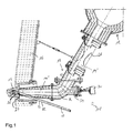
- Fig.1 shows a cut through an installation used for carrying out the method according to the present invention.
- Fig.1 shows a hot blast system 10 having a bustle pipe 12 encircling a blast furnace and a plurality of tuyere stocks 14 for feeding hot blast air through an opening in the blast furnace wall 16 into the furnace hearth of the blast furnace.
- the tuyere stocks 14 are refractory-lined steel tubes for supplying the hot blast air from the bustle pipe 12 to the blast furnace. They each generally comprise an angled first portion 14', also referred to as downcomer, and a substantially horizontal second portion 14", also referred to as blow pipe.
- the second portion 14" has a convex spherical nose, designed and arranged so as to come into airtight engagement with a concave end of a tuyere 15 installed in the opening in the furnace wall 16.
- the first portion 14' is arranged at an angle with respect to the horizontal portion 14" and is connected to the bustle pipe 12 for leading the hot blast air from the bustle pipe 12 to the second portion 14".
- a pulverised coal injection lance 18 is provided for injecting pulverised coal into the blast furnace.
- the lance 18 is of the oxycoal type and comprises an inner pipe 20 for conveying pulverised coal and an outer pipe 22, coaxially arranged around the inner pipe 20, for conveying combustive gas.
- the inner pipe 20 forms a separation wall for separating the pulverised coal from the combustive gas all the way through the lance 18, until the pulverised coal and the combustive gas are allowed to mix at a lance tip 24 of the pulverised coal injection lance 18.
- the pulverised coal injection lance 18 is arranged in such a way that its lance tip 24 is situated in an exit region 26 of the tuyere 15, near the opening in the furnace wall 16.
- pulverised coal and combustive gas typically oxygen
- oxygen is fed through the pulverised coal injection lance 18 into the second portion 14" of the tuyere stock 14.
- the pulverised coal comes into contact with the oxygen and forms a mixture.
- the combustion conditions are such that this mixture ignites and a flame bums at the lance tip 24 inside the tuyere 15.
- the pulverised coal is burnt preferably completely inside the tuyere 15.
- the reignition of the flame is achieved by temporarily reducing the amount of oxygen fed through the lance 18. This alters the combustion conditions and the flame reignites when the oxygen supply is restored.
- the temporary reduction of the flow of combustive gas may cause heating and/or turbulences at the lance tip 24, which encourages reignition of the flame.
- the determination of whether or not the flame at the lance tip 24 is burning is, according to the present invention, based on systems currently used for determining a blockage of the tuyere 15. Such systems are already installed on blast furnace installations and do therefore not incur any additional costs.
- Such blockage detection systems may e.g. include means for measuring a pressure drop in the hot blast air across the first portion 14' of the tuyere stock 14. to this effect, the first portion 14' may comprise a Venturi type cross-section reduction 28.
- Such blockage detection systems may alternatively or additionally include detection means 30 arranged in axial alignment with the second portion 14" of the tuyere stock 14.
- detection means 30 arranged in axial alignment with the second portion 14" of the tuyere stock 14.
- the latter can comprise an axial extension pipe 34 at the end of which the detection means 30 may be arranged.
- the detection means 30 can be a light intensity detector for measuring light intensity in the tuyere 15. A reduction in light intensity can be interpreted as an indication that the flame at the lance tip 24 is no longer burning.
- the detection means 30 can be a camera for monitoring an image from the tuyere 15.
- the captured image can be analysed by an image processor. Changes in some characteristics of the image from the tuyere 15 can also be interpreted as an indication that the flame at the lance tip 24 is no longer burning.
Landscapes
- Engineering & Computer Science (AREA)
- Chemical & Material Sciences (AREA)
- Mechanical Engineering (AREA)
- General Engineering & Computer Science (AREA)
- Manufacturing & Machinery (AREA)
- Materials Engineering (AREA)
- Metallurgy (AREA)
- Organic Chemistry (AREA)
- Manufacture Of Iron (AREA)
- Blast Furnaces (AREA)
Claims (16)
- Verfahren zum Zuführen von Kohlenstaub in einen Hochofen, umfassend:Bereitstellen eines Düsenstocks zum Blasen von heißer Blasluft aus einer Ringleitung in einen Ofenherd eines Hochofens durch eine Düse, die in einer Öffnung in der Ofenwand installiert ist;Bereitstellen einer Kohlenstaub-Einspritzlanze zum Zuführen von Kohlenstaub in die Düse, wobei die Kohlenstaub-Einspritzlanze ein Innenrohr zum Befördern von Kohlenstaub und ein koaxial um das Innenrohr angeordnetes Außenrohr zum Befördern von Brenngas aufweist, wobei das Innenrohr eine Trennwand zum Trennen des Kohlenstaubs von dem Brenngas bildet, wobei die Kohlenstaub-Einspritzlanze eine in der Düse angeordnete Lanzenspitze aufweist;Ermöglichen des Bildens eines Gemischs aus Kohlenstaub und Brenngas an der Lanzenspitze durch den Kohlenstaub und das Brenngas; undVerbrennen des Gemischs aus Kohlenstaub und Brenngas in der Düse,gekennzeichnet durchÜberwachen, ob eine Flamme an der Lanzenspitze brennt oder nicht; undbei Bestimmung, dass die Flamme an der Lanzenspitze nicht brennt, Wiederanzünden der Flamme durch vorübergehendes Verringern des Stroms von Brenngas durch die Kohlenstaub-Einspritzlanze.
- Verfahren nach Anspruch 1, wobei während der Strom von Brenngas durch die Kohlenstaub-Einspritzlanze vorübergehend verringert wird, der Strom von Kohlenstaub durch die Kohlenstaub-Einspritzlanze beibehalten wird.
- Verfahren nach Anspruch 1 oder 2, wobei das Überwachen des Brennens einer Flamme an der Lanzenspitze kontinuierlich durchgeführt wird.
- Verfahren nach einem der Ansprüche 1 bis 3, wobei das Überwachen des Brennens einer Flamme an der Lanzenspitze durch Düsenblockier-Erkennungsmittel durchgeführt wird.
- Verfahren nach einem der Ansprüche 1 bis 4, umfassend:Ausrüsten von Düsenblockier-Erkennungsmitteln mit Drucksensoren zum Messen eines Druckabfalls in der heißen Blasluft über einen Abschnitt des Düsenstocks stromaufwärts der Lanzenspitze; undÜberwachen des Druckabfalls über den Abschnitt des Düsenstocks und, darauf basierend, Bestimmen, ob die Flamme an der Lanzenspitze brennt oder nicht.
- Verfahren nach Anspruch 5, wobei der Druckabfall zwischen der Ringleitung und einem Abschnitt des Düsenstocks stromaufwärts der Lanzenspitze gemessen wird.
- Verfahren nach Anspruch 5 oder 6, wobei geschlossen wird, dass die Flamme an der Lanzenspitze nicht brennt, wenn der Druckabfall um eine vorbestimmte Menge erhöht ist.
- Verfahren nach Anspruch 7, wobei geschlossen wird, dass die Flamme an der Lanzenspitze nicht brennt, wenn der Druckabfall um eine vorbestimmte Menge für eine vorbestimmte Zeitdauer erhöht ist.
- Verfahren nach einem der Ansprüche 1 bis 8, umfassend:Ausrüsten des Düsenstocks mit einem im Wesentlichen horizontalen Rüssel zum Blasen von heißer Blasluft in den Ofenherd des Hochofens;Ausrüsten von Düsenblockier-Erkennungsmitteln mit einem Lichtintensitätsdetektor, der in axialer Ausrichtung mit dem Rüssel angeordnet ist; undÜberwachen der Lichtintensität in der Düse und, darauf basierend, Bestimmen, ob die Flamme an der Lanzenspitze brennt oder nicht.
- Verfahren nach Anspruch 9, wobei geschlossen wird, dass die Flamme an der Lanzenspitze nicht brennt, wenn die Lichtintensität in der Düse um einen vorbestimmten Betrag vermindert ist.
- Verfahren nach Anspruch 10, wobei geschlossen wird, dass die Flamme an der Lanzenspitze nicht brennt, wenn die Lichtintensität in der Düse um einen vorbestimmten Betrag für eine vorbestimmte Zeitdauer vermindert ist.
- Verfahren nach einem der Ansprüche 1 bis 11, umfassend:Ausrüsten des Düsenstocks mit einem im Wesentlichen horizontalen Rüssel zum Blasen von heißer Blasluft in den Ofenherd des Hochofens;Ausrüsten von Düsenblockier-Erkennungsmitteln mit einer Kamera, die in axialer Ausrichtung mit dem Rüssel angeordnet ist; undÜberwachen eines Bildes in der Düse und, basierend darauf, Bestimmen, ob die Flamme an der Spitze der Kohlenstaub-Einspritzlanze brennt oder nicht.
- Verfahren nach Anspruch 12, wobei geschlossen wird, dass die Flamme an der Lanzenspitze nicht brennt, wenn sich das Bild von der Düse nach einem vorbestimmten Schema ändert.
- Verfahren nach Anspruch 12 oder 13, wobei geschlossen wird, dass die Flamme an der Lanzenspitze nicht brennt, wenn das Bild von der Düse eine ausreichende Ähnlichkeit mit einem vorbestimmten Musterbild hat.
- Verfahren nach einem der Ansprüche 12 bis 14, wobei das Bild von der Düse durch einen Bildverarbeitungsalgorithmus analysiert wird.
- Verfahren nach einem der Ansprüche 1 bis 3, umfassend:Ausrüsten des Düsenstocks mit einem im Wesentlichen horizontalen Rüssel zum Blasen von heißer Blasluft in den Ofenherd des Hochofens;Bereitstellen von Temperaturmessmitteln, die in axialer Ausrichtung mit dem Rüssel angeordnet sind; undÜberwachen einer Temperatur in oder nahe der Düse und, darauf basierend, Bestimmen, ob die Flamme an der Spitze der Kohlenstaub-Einspritzlanze brennt oder nicht.
Applications Claiming Priority (2)
| Application Number | Priority Date | Filing Date | Title |
|---|---|---|---|
| LU91445A LU91445B1 (en) | 2008-05-23 | 2008-05-23 | Method for feeding pulverised coal into a blast furnace |
| PCT/EP2009/056211 WO2009141419A1 (en) | 2008-05-23 | 2009-05-22 | Method for feeding pulverised coal into a blast furnace |
Publications (2)
| Publication Number | Publication Date |
|---|---|
| EP2286166A1 EP2286166A1 (de) | 2011-02-23 |
| EP2286166B1 true EP2286166B1 (de) | 2015-01-07 |
Family
ID=40202949
Family Applications (1)
| Application Number | Title | Priority Date | Filing Date |
|---|---|---|---|
| EP09749909.9A Active EP2286166B1 (de) | 2008-05-23 | 2009-05-22 | Verfahren zur zufuhr pulverisierter kohle in einen gasverbrennungsofen |
Country Status (12)
| Country | Link |
|---|---|
| US (1) | US8652395B2 (de) |
| EP (1) | EP2286166B1 (de) |
| JP (1) | JP5568081B2 (de) |
| KR (1) | KR101580550B1 (de) |
| CN (1) | CN102037304B (de) |
| AU (1) | AU2009248720B2 (de) |
| BR (1) | BRPI0913080B1 (de) |
| CA (1) | CA2721723C (de) |
| LU (1) | LU91445B1 (de) |
| RU (1) | RU2482193C2 (de) |
| UA (1) | UA99767C2 (de) |
| WO (1) | WO2009141419A1 (de) |
Families Citing this family (15)
| Publication number | Priority date | Publication date | Assignee | Title |
|---|---|---|---|---|
| LU91691B1 (en) * | 2010-05-26 | 2011-11-28 | Wurth Paul Sa | Tuyere stock arrangement of a blast furnace |
| LU91764B1 (en) * | 2010-12-10 | 2012-06-11 | Wurth Paul Sa | Tuyere stock of a shaft furnace and hot gas distribution system comprising a plurality of such tuyere stocks |
| DE102011107326A1 (de) * | 2011-07-14 | 2013-01-17 | Linde Aktiengesellschaft | Schachtofen und Verfahren zum Betreiben desselben |
| US8919670B2 (en) | 2011-12-09 | 2014-12-30 | United States Steel Corporation | Injection lance with variable swirl |
| KR101675711B1 (ko) * | 2013-04-19 | 2016-11-11 | 제이에프이 스틸 가부시키가이샤 | 고로 조업 방법 |
| KR101704982B1 (ko) * | 2013-07-29 | 2017-02-08 | 제이에프이 스틸 가부시키가이샤 | 이상 검지 방법 및 고로 조업 방법 |
| RU2678548C1 (ru) | 2015-02-17 | 2019-01-29 | Тата Стил Лимитед | Способ и устройство удаления закупорки в фурме |
| JP6269532B2 (ja) | 2015-03-02 | 2018-01-31 | Jfeスチール株式会社 | 高炉操業方法 |
| JP6269533B2 (ja) | 2015-03-02 | 2018-01-31 | Jfeスチール株式会社 | 高炉操業方法 |
| AT517642B1 (de) * | 2015-09-02 | 2018-07-15 | Primetals Technologies Austria GmbH | Hochofen mit energieautarker Beobachtung von Kohlenstoffeinblasung |
| TWI623621B (zh) * | 2016-08-18 | 2018-05-11 | 中國鋼鐵股份有限公司 | 高爐鼓風伸縮管 |
| CN111328349B (zh) * | 2017-06-22 | 2022-06-10 | 乔治洛德方法研究和开发液化空气有限公司 | 将工艺流体注入到具有注入器状态测试的竖炉中 |
| CN112708471B (zh) * | 2019-10-25 | 2021-11-30 | 中国石油化工股份有限公司 | 一种高效煤气化反应装置和高效煤气化反应方法 |
| JP7444491B2 (ja) * | 2021-02-25 | 2024-03-06 | エクセロ カンパニー,リミテッド | 送風支管、送風支管の製造方法及び溶解炉送風システム |
| JP7472864B2 (ja) * | 2021-06-23 | 2024-04-23 | Jfeスチール株式会社 | 気体還元材の吹込み方法および高炉用羽口 |
Family Cites Families (25)
| Publication number | Priority date | Publication date | Assignee | Title |
|---|---|---|---|---|
| JPS5110168B1 (de) * | 1971-04-30 | 1976-04-02 | ||
| GB1491128A (en) | 1974-06-10 | 1977-11-09 | Promecan Sisson Lehmann | Adjustable stop device for a part to be worked by a machine-tool |
| SU823429A1 (ru) * | 1979-07-31 | 1981-04-27 | Институт черной металлургии | Устройство дл регулировани по-дАчи пылЕугОльНОгО ТОплиВА B дОМЕННуюпЕчь |
| LU82036A1 (fr) * | 1979-12-27 | 1980-04-23 | Wurth Anciens Ets Paul | Procede et installation d'injection de quantites dosees de matieres pulverulentes par voie pneumatique dans une enceinte se trouvant sous pression variable et application a un four a cuve |
| JPS60125307A (ja) * | 1983-12-07 | 1985-07-04 | Kawasaki Steel Corp | 高炉羽口へ通じる粉体吹込み管の閉塞検知方法 |
| JPH02213406A (ja) * | 1989-02-15 | 1990-08-24 | Kawasaki Steel Corp | 高炉羽口からの燃料吹込方法 |
| JPH02263907A (ja) * | 1989-04-04 | 1990-10-26 | Sumitomo Metal Ind Ltd | 高炉羽口粉体吹き込み操業法 |
| JPH0694564B2 (ja) * | 1990-11-30 | 1994-11-24 | 住友金属工業株式会社 | 高炉への粉体燃料吹込方法 |
| JPH0688109A (ja) * | 1991-01-16 | 1994-03-29 | Sumitomo Metal Ind Ltd | 高炉羽口微粉炭吹き込み方法 |
| JP2994141B2 (ja) * | 1992-06-16 | 1999-12-27 | 川崎製鉄株式会社 | 高炉への粉体燃料の吹込み方法 |
| DE69322002T2 (de) * | 1992-07-01 | 1999-04-01 | Paul Wurth S.A., Luxemburg/Luxembourg | Vorrichtung zum Einblasen von Kohlenstaub in einen Hochofen |
| US5481247A (en) * | 1994-07-29 | 1996-01-02 | Alexander; James M. | Blast furnace tuyere sensor system |
| US5397108A (en) * | 1994-07-29 | 1995-03-14 | Alexander; James M. | Peepsight for blast furnace tuyere sensor system |
| CN2289798Y (zh) * | 1995-11-09 | 1998-09-02 | 冶金工业部鞍山热能研究院 | 炼铁高炉用新型富氧喷煤装置 |
| CN1038430C (zh) * | 1995-11-21 | 1998-05-20 | 北京市麒跃技术研究所 | 高炉喷吹煤粉快速燃烧方法和设备 |
| US6080223A (en) * | 1997-08-29 | 2000-06-27 | Bethlehem Steel Corporation | Flame detection monitoring system for detecting blockages in blast furnace injection paths |
| JPH11343511A (ja) * | 1998-06-02 | 1999-12-14 | Nkk Corp | 高炉の微粉炭吹き込み方法 |
| JP3379946B2 (ja) * | 1998-08-13 | 2003-02-24 | ポハング アイアン アンド スチール カンパニイ リミテッド | 粉砕石炭の導入装置 |
| US6059562A (en) * | 1998-08-13 | 2000-05-09 | Bethlehem Steel Corporation | Gas appliance with automatic gas shut-off device responsive to flame outage |
| KR100380747B1 (ko) * | 1999-07-19 | 2003-04-18 | 주식회사 포스코 | 이중관을 이용한 미분탄 취입장치 |
| KR100465504B1 (ko) * | 1998-11-20 | 2005-04-06 | 한국타이어 주식회사 | 타이어 제조용 분할 금형의 진원도 측정장치 |
| JP2000226609A (ja) * | 1999-02-08 | 2000-08-15 | Nkk Corp | ランスの異常監視方法 |
| JP4044711B2 (ja) * | 1999-12-28 | 2008-02-06 | 新日本製鐵株式会社 | 高炉への微粉炭吹き込み操業時の炉芯昇熱方法 |
| CN1289035A (zh) * | 2000-08-28 | 2001-03-28 | 宝山钢铁股份有限公司 | 脉动式喷煤方法及其装置 |
| JP4288230B2 (ja) * | 2004-12-28 | 2009-07-01 | 新日本製鐵株式会社 | 高炉の操業方法 |
-
2008
- 2008-05-23 LU LU91445A patent/LU91445B1/fr active
-
2009
- 2009-05-22 JP JP2011509992A patent/JP5568081B2/ja active Active
- 2009-05-22 KR KR1020107025230A patent/KR101580550B1/ko active Active
- 2009-05-22 BR BRPI0913080-2A patent/BRPI0913080B1/pt active IP Right Grant
- 2009-05-22 RU RU2010152010/02A patent/RU2482193C2/ru active
- 2009-05-22 CA CA2721723A patent/CA2721723C/en not_active Expired - Fee Related
- 2009-05-22 WO PCT/EP2009/056211 patent/WO2009141419A1/en not_active Ceased
- 2009-05-22 EP EP09749909.9A patent/EP2286166B1/de active Active
- 2009-05-22 AU AU2009248720A patent/AU2009248720B2/en active Active
- 2009-05-22 UA UAA201015430A patent/UA99767C2/ru unknown
- 2009-05-22 US US12/993,225 patent/US8652395B2/en active Active
- 2009-05-22 CN CN2009801178460A patent/CN102037304B/zh active Active
Also Published As
| Publication number | Publication date |
|---|---|
| RU2482193C2 (ru) | 2013-05-20 |
| EP2286166A1 (de) | 2011-02-23 |
| AU2009248720A1 (en) | 2009-11-26 |
| BRPI0913080A2 (pt) | 2020-11-03 |
| RU2010152010A (ru) | 2012-06-27 |
| LU91445B1 (en) | 2009-11-24 |
| CA2721723A1 (en) | 2009-11-26 |
| UA99767C2 (ru) | 2012-09-25 |
| KR20110014585A (ko) | 2011-02-11 |
| US8652395B2 (en) | 2014-02-18 |
| CA2721723C (en) | 2014-08-26 |
| CN102037304B (zh) | 2013-03-20 |
| WO2009141419A1 (en) | 2009-11-26 |
| KR101580550B1 (ko) | 2016-01-11 |
| JP2011523439A (ja) | 2011-08-11 |
| AU2009248720B2 (en) | 2014-07-03 |
| US20110180978A1 (en) | 2011-07-28 |
| JP5568081B2 (ja) | 2014-08-06 |
| CN102037304A (zh) | 2011-04-27 |
| BRPI0913080B1 (pt) | 2021-09-28 |
Similar Documents
| Publication | Publication Date | Title |
|---|---|---|
| EP2286166B1 (de) | Verfahren zur zufuhr pulverisierter kohle in einen gasverbrennungsofen | |
| EP2577200B1 (de) | Düsenstockanordnung eines hochofens | |
| US7077069B2 (en) | U-type slag-tap firing boiler and method of operating the boiler | |
| US9309578B2 (en) | Blast furnace operating method and tube bundle-type lance | |
| JP4760985B2 (ja) | 高炉操業方法 | |
| JPH01268809A (ja) | 微粉炭バーナ | |
| JP5271660B2 (ja) | 旋回燃焼ボイラ | |
| JP4288230B2 (ja) | 高炉の操業方法 | |
| JP4345506B2 (ja) | 高炉への固体燃料吹き込み方法 | |
| CN223527694U (zh) | 电缆组件 | |
| JP6699629B2 (ja) | 酸素高炉の操業方法 | |
| JP2024504590A (ja) | 気体流中の可燃性物質の監視 | |
| JPH10141632A (ja) | 焼却炉の燃焼制御方法 | |
| JPH09159133A (ja) | 燃焼装置 |
Legal Events
| Date | Code | Title | Description |
|---|---|---|---|
| PUAI | Public reference made under article 153(3) epc to a published international application that has entered the european phase |
Free format text: ORIGINAL CODE: 0009012 |
|
| 17P | Request for examination filed |
Effective date: 20101014 |
|
| AK | Designated contracting states |
Kind code of ref document: A1 Designated state(s): AT BE BG CH CY CZ DE DK EE ES FI FR GB GR HR HU IE IS IT LI LT LU LV MC MK MT NL NO PL PT RO SE SI SK TR |
|
| AX | Request for extension of the european patent |
Extension state: AL BA RS |
|
| DAX | Request for extension of the european patent (deleted) | ||
| GRAP | Despatch of communication of intention to grant a patent |
Free format text: ORIGINAL CODE: EPIDOSNIGR1 |
|
| INTG | Intention to grant announced |
Effective date: 20140723 |
|
| GRAS | Grant fee paid |
Free format text: ORIGINAL CODE: EPIDOSNIGR3 |
|
| GRAA | (expected) grant |
Free format text: ORIGINAL CODE: 0009210 |
|
| AK | Designated contracting states |
Kind code of ref document: B1 Designated state(s): AT BE BG CH CY CZ DE DK EE ES FI FR GB GR HR HU IE IS IT LI LT LU LV MC MK MT NL NO PL PT RO SE SI SK TR |
|
| REG | Reference to a national code |
Ref country code: GB Ref legal event code: FG4D |
|
| REG | Reference to a national code |
Ref country code: CH Ref legal event code: EP |
|
| REG | Reference to a national code |
Ref country code: IE Ref legal event code: FG4D |
|
| REG | Reference to a national code |
Ref country code: AT Ref legal event code: REF Ref document number: 706001 Country of ref document: AT Kind code of ref document: T Effective date: 20150215 |
|
| REG | Reference to a national code |
Ref country code: DE Ref legal event code: R096 Ref document number: 602009028829 Country of ref document: DE Effective date: 20150226 |
|
| REG | Reference to a national code |
Ref country code: NL Ref legal event code: T3 |
|
| REG | Reference to a national code |
Ref country code: LT Ref legal event code: MG4D |
|
| PG25 | Lapsed in a contracting state [announced via postgrant information from national office to epo] |
Ref country code: LT Free format text: LAPSE BECAUSE OF FAILURE TO SUBMIT A TRANSLATION OF THE DESCRIPTION OR TO PAY THE FEE WITHIN THE PRESCRIBED TIME-LIMIT Effective date: 20150107 Ref country code: ES Free format text: LAPSE BECAUSE OF FAILURE TO SUBMIT A TRANSLATION OF THE DESCRIPTION OR TO PAY THE FEE WITHIN THE PRESCRIBED TIME-LIMIT Effective date: 20150107 Ref country code: SE Free format text: LAPSE BECAUSE OF FAILURE TO SUBMIT A TRANSLATION OF THE DESCRIPTION OR TO PAY THE FEE WITHIN THE PRESCRIBED TIME-LIMIT Effective date: 20150107 Ref country code: FI Free format text: LAPSE BECAUSE OF FAILURE TO SUBMIT A TRANSLATION OF THE DESCRIPTION OR TO PAY THE FEE WITHIN THE PRESCRIBED TIME-LIMIT Effective date: 20150107 Ref country code: NO Free format text: LAPSE BECAUSE OF FAILURE TO SUBMIT A TRANSLATION OF THE DESCRIPTION OR TO PAY THE FEE WITHIN THE PRESCRIBED TIME-LIMIT Effective date: 20150407 Ref country code: HR Free format text: LAPSE BECAUSE OF FAILURE TO SUBMIT A TRANSLATION OF THE DESCRIPTION OR TO PAY THE FEE WITHIN THE PRESCRIBED TIME-LIMIT Effective date: 20150107 Ref country code: BG Free format text: LAPSE BECAUSE OF FAILURE TO SUBMIT A TRANSLATION OF THE DESCRIPTION OR TO PAY THE FEE WITHIN THE PRESCRIBED TIME-LIMIT Effective date: 20150407 |
|
| PG25 | Lapsed in a contracting state [announced via postgrant information from national office to epo] |
Ref country code: LV Free format text: LAPSE BECAUSE OF FAILURE TO SUBMIT A TRANSLATION OF THE DESCRIPTION OR TO PAY THE FEE WITHIN THE PRESCRIBED TIME-LIMIT Effective date: 20150107 Ref country code: PL Free format text: LAPSE BECAUSE OF FAILURE TO SUBMIT A TRANSLATION OF THE DESCRIPTION OR TO PAY THE FEE WITHIN THE PRESCRIBED TIME-LIMIT Effective date: 20150107 Ref country code: GR Free format text: LAPSE BECAUSE OF FAILURE TO SUBMIT A TRANSLATION OF THE DESCRIPTION OR TO PAY THE FEE WITHIN THE PRESCRIBED TIME-LIMIT Effective date: 20150408 Ref country code: IS Free format text: LAPSE BECAUSE OF FAILURE TO SUBMIT A TRANSLATION OF THE DESCRIPTION OR TO PAY THE FEE WITHIN THE PRESCRIBED TIME-LIMIT Effective date: 20150507 |
|
| REG | Reference to a national code |
Ref country code: DE Ref legal event code: R097 Ref document number: 602009028829 Country of ref document: DE |
|
| PG25 | Lapsed in a contracting state [announced via postgrant information from national office to epo] |
Ref country code: SK Free format text: LAPSE BECAUSE OF FAILURE TO SUBMIT A TRANSLATION OF THE DESCRIPTION OR TO PAY THE FEE WITHIN THE PRESCRIBED TIME-LIMIT Effective date: 20150107 Ref country code: DK Free format text: LAPSE BECAUSE OF FAILURE TO SUBMIT A TRANSLATION OF THE DESCRIPTION OR TO PAY THE FEE WITHIN THE PRESCRIBED TIME-LIMIT Effective date: 20150107 Ref country code: EE Free format text: LAPSE BECAUSE OF FAILURE TO SUBMIT A TRANSLATION OF THE DESCRIPTION OR TO PAY THE FEE WITHIN THE PRESCRIBED TIME-LIMIT Effective date: 20150107 Ref country code: RO Free format text: LAPSE BECAUSE OF FAILURE TO SUBMIT A TRANSLATION OF THE DESCRIPTION OR TO PAY THE FEE WITHIN THE PRESCRIBED TIME-LIMIT Effective date: 20150107 Ref country code: CZ Free format text: LAPSE BECAUSE OF FAILURE TO SUBMIT A TRANSLATION OF THE DESCRIPTION OR TO PAY THE FEE WITHIN THE PRESCRIBED TIME-LIMIT Effective date: 20150107 |
|
| PLBE | No opposition filed within time limit |
Free format text: ORIGINAL CODE: 0009261 |
|
| STAA | Information on the status of an ep patent application or granted ep patent |
Free format text: STATUS: NO OPPOSITION FILED WITHIN TIME LIMIT |
|
| 26N | No opposition filed |
Effective date: 20151008 |
|
| REG | Reference to a national code |
Ref country code: CH Ref legal event code: PL |
|
| PG25 | Lapsed in a contracting state [announced via postgrant information from national office to epo] |
Ref country code: LI Free format text: LAPSE BECAUSE OF NON-PAYMENT OF DUE FEES Effective date: 20150531 Ref country code: LU Free format text: LAPSE BECAUSE OF FAILURE TO SUBMIT A TRANSLATION OF THE DESCRIPTION OR TO PAY THE FEE WITHIN THE PRESCRIBED TIME-LIMIT Effective date: 20150522 Ref country code: CH Free format text: LAPSE BECAUSE OF NON-PAYMENT OF DUE FEES Effective date: 20150531 Ref country code: MC Free format text: LAPSE BECAUSE OF FAILURE TO SUBMIT A TRANSLATION OF THE DESCRIPTION OR TO PAY THE FEE WITHIN THE PRESCRIBED TIME-LIMIT Effective date: 20150107 |
|
| REG | Reference to a national code |
Ref country code: IE Ref legal event code: MM4A |
|
| PG25 | Lapsed in a contracting state [announced via postgrant information from national office to epo] |
Ref country code: SI Free format text: LAPSE BECAUSE OF FAILURE TO SUBMIT A TRANSLATION OF THE DESCRIPTION OR TO PAY THE FEE WITHIN THE PRESCRIBED TIME-LIMIT Effective date: 20150107 |
|
| REG | Reference to a national code |
Ref country code: FR Ref legal event code: PLFP Year of fee payment: 8 |
|
| PG25 | Lapsed in a contracting state [announced via postgrant information from national office to epo] |
Ref country code: IE Free format text: LAPSE BECAUSE OF NON-PAYMENT OF DUE FEES Effective date: 20150522 |
|
| REG | Reference to a national code |
Ref country code: AT Ref legal event code: UEP Ref document number: 706001 Country of ref document: AT Kind code of ref document: T Effective date: 20150107 |
|
| PG25 | Lapsed in a contracting state [announced via postgrant information from national office to epo] |
Ref country code: MT Free format text: LAPSE BECAUSE OF FAILURE TO SUBMIT A TRANSLATION OF THE DESCRIPTION OR TO PAY THE FEE WITHIN THE PRESCRIBED TIME-LIMIT Effective date: 20150107 |
|
| REG | Reference to a national code |
Ref country code: FR Ref legal event code: PLFP Year of fee payment: 9 |
|
| PG25 | Lapsed in a contracting state [announced via postgrant information from national office to epo] |
Ref country code: HU Free format text: LAPSE BECAUSE OF FAILURE TO SUBMIT A TRANSLATION OF THE DESCRIPTION OR TO PAY THE FEE WITHIN THE PRESCRIBED TIME-LIMIT; INVALID AB INITIO Effective date: 20090522 |
|
| PG25 | Lapsed in a contracting state [announced via postgrant information from national office to epo] |
Ref country code: CY Free format text: LAPSE BECAUSE OF FAILURE TO SUBMIT A TRANSLATION OF THE DESCRIPTION OR TO PAY THE FEE WITHIN THE PRESCRIBED TIME-LIMIT Effective date: 20150107 |
|
| REG | Reference to a national code |
Ref country code: FR Ref legal event code: PLFP Year of fee payment: 10 |
|
| PG25 | Lapsed in a contracting state [announced via postgrant information from national office to epo] |
Ref country code: PT Free format text: LAPSE BECAUSE OF FAILURE TO SUBMIT A TRANSLATION OF THE DESCRIPTION OR TO PAY THE FEE WITHIN THE PRESCRIBED TIME-LIMIT Effective date: 20150107 Ref country code: MK Free format text: LAPSE BECAUSE OF FAILURE TO SUBMIT A TRANSLATION OF THE DESCRIPTION OR TO PAY THE FEE WITHIN THE PRESCRIBED TIME-LIMIT Effective date: 20150107 |
|
| P01 | Opt-out of the competence of the unified patent court (upc) registered |
Effective date: 20230524 |
|
| PGFP | Annual fee paid to national office [announced via postgrant information from national office to epo] |
Ref country code: NL Payment date: 20250416 Year of fee payment: 17 |
|
| PGFP | Annual fee paid to national office [announced via postgrant information from national office to epo] |
Ref country code: DE Payment date: 20250415 Year of fee payment: 17 |
|
| PGFP | Annual fee paid to national office [announced via postgrant information from national office to epo] |
Ref country code: GB Payment date: 20250415 Year of fee payment: 17 |
|
| PGFP | Annual fee paid to national office [announced via postgrant information from national office to epo] |
Ref country code: BE Payment date: 20250415 Year of fee payment: 17 Ref country code: IT Payment date: 20250507 Year of fee payment: 17 |
|
| PGFP | Annual fee paid to national office [announced via postgrant information from national office to epo] |
Ref country code: FR Payment date: 20250415 Year of fee payment: 17 |
|
| PGFP | Annual fee paid to national office [announced via postgrant information from national office to epo] |
Ref country code: AT Payment date: 20250416 Year of fee payment: 17 |
|
| PGFP | Annual fee paid to national office [announced via postgrant information from national office to epo] |
Ref country code: TR Payment date: 20250514 Year of fee payment: 17 |