EP2286100B1 - Radlageranordnung mit fettverteilerring - Google Patents
Radlageranordnung mit fettverteilerring Download PDFInfo
- Publication number
- EP2286100B1 EP2286100B1 EP09753730.2A EP09753730A EP2286100B1 EP 2286100 B1 EP2286100 B1 EP 2286100B1 EP 09753730 A EP09753730 A EP 09753730A EP 2286100 B1 EP2286100 B1 EP 2286100B1
- Authority
- EP
- European Patent Office
- Prior art keywords
- grease
- wheel bearing
- bearing arrangement
- distributor ring
- ring
- Prior art date
- Legal status (The legal status is an assumption and is not a legal conclusion. Google has not performed a legal analysis and makes no representation as to the accuracy of the status listed.)
- Not-in-force
Links
- 239000004519 grease Substances 0.000 title claims description 154
- 238000005096 rolling process Methods 0.000 claims description 48
- 239000000463 material Substances 0.000 claims description 11
- 230000001050 lubricating effect Effects 0.000 claims description 8
- 239000004033 plastic Substances 0.000 claims description 5
- 229920003023 plastic Polymers 0.000 claims description 5
- 210000001503 joint Anatomy 0.000 claims 2
- 238000009826 distribution Methods 0.000 description 57
- 238000013461 design Methods 0.000 description 9
- 230000000694 effects Effects 0.000 description 6
- 238000005461 lubrication Methods 0.000 description 5
- 238000011161 development Methods 0.000 description 3
- 239000000314 lubricant Substances 0.000 description 3
- 230000000712 assembly Effects 0.000 description 2
- 238000000429 assembly Methods 0.000 description 2
- 230000015572 biosynthetic process Effects 0.000 description 2
- 238000010276 construction Methods 0.000 description 2
- 238000005755 formation reaction Methods 0.000 description 2
- 238000004519 manufacturing process Methods 0.000 description 2
- 238000000034 method Methods 0.000 description 2
- 239000000243 solution Substances 0.000 description 2
- 230000003111 delayed effect Effects 0.000 description 1
- 230000001066 destructive effect Effects 0.000 description 1
- 239000011152 fibreglass Substances 0.000 description 1
- 239000000945 filler Substances 0.000 description 1
- 238000002347 injection Methods 0.000 description 1
- 239000007924 injection Substances 0.000 description 1
- 238000001746 injection moulding Methods 0.000 description 1
- 238000012986 modification Methods 0.000 description 1
- 230000004048 modification Effects 0.000 description 1
- 230000002093 peripheral effect Effects 0.000 description 1
- 238000003825 pressing Methods 0.000 description 1
- 239000007787 solid Substances 0.000 description 1
- 230000003068 static effect Effects 0.000 description 1
- 238000012546 transfer Methods 0.000 description 1
Images



Classifications
-
- F—MECHANICAL ENGINEERING; LIGHTING; HEATING; WEAPONS; BLASTING
- F16—ENGINEERING ELEMENTS AND UNITS; GENERAL MEASURES FOR PRODUCING AND MAINTAINING EFFECTIVE FUNCTIONING OF MACHINES OR INSTALLATIONS; THERMAL INSULATION IN GENERAL
- F16C—SHAFTS; FLEXIBLE SHAFTS; ELEMENTS OR CRANKSHAFT MECHANISMS; ROTARY BODIES OTHER THAN GEARING ELEMENTS; BEARINGS
- F16C33/00—Parts of bearings; Special methods for making bearings or parts thereof
- F16C33/30—Parts of ball or roller bearings
- F16C33/66—Special parts or details in view of lubrication
- F16C33/6603—Special parts or details in view of lubrication with grease as lubricant
- F16C33/6622—Details of supply and/or removal of the grease, e.g. purging grease
- F16C33/6625—Controlling or conditioning the grease supply
-
- F—MECHANICAL ENGINEERING; LIGHTING; HEATING; WEAPONS; BLASTING
- F16—ENGINEERING ELEMENTS AND UNITS; GENERAL MEASURES FOR PRODUCING AND MAINTAINING EFFECTIVE FUNCTIONING OF MACHINES OR INSTALLATIONS; THERMAL INSULATION IN GENERAL
- F16C—SHAFTS; FLEXIBLE SHAFTS; ELEMENTS OR CRANKSHAFT MECHANISMS; ROTARY BODIES OTHER THAN GEARING ELEMENTS; BEARINGS
- F16C19/00—Bearings with rolling contact, for exclusively rotary movement
- F16C19/22—Bearings with rolling contact, for exclusively rotary movement with bearing rollers essentially of the same size in one or more circular rows, e.g. needle bearings
- F16C19/34—Bearings with rolling contact, for exclusively rotary movement with bearing rollers essentially of the same size in one or more circular rows, e.g. needle bearings for both radial and axial load
- F16C19/36—Bearings with rolling contact, for exclusively rotary movement with bearing rollers essentially of the same size in one or more circular rows, e.g. needle bearings for both radial and axial load with a single row of rollers
- F16C19/364—Bearings with rolling contact, for exclusively rotary movement with bearing rollers essentially of the same size in one or more circular rows, e.g. needle bearings for both radial and axial load with a single row of rollers with tapered rollers, i.e. rollers having essentially the shape of a truncated cone
-
- F—MECHANICAL ENGINEERING; LIGHTING; HEATING; WEAPONS; BLASTING
- F16—ENGINEERING ELEMENTS AND UNITS; GENERAL MEASURES FOR PRODUCING AND MAINTAINING EFFECTIVE FUNCTIONING OF MACHINES OR INSTALLATIONS; THERMAL INSULATION IN GENERAL
- F16C—SHAFTS; FLEXIBLE SHAFTS; ELEMENTS OR CRANKSHAFT MECHANISMS; ROTARY BODIES OTHER THAN GEARING ELEMENTS; BEARINGS
- F16C19/00—Bearings with rolling contact, for exclusively rotary movement
- F16C19/54—Systems consisting of a plurality of bearings with rolling friction
- F16C19/541—Systems consisting of juxtaposed rolling bearings including at least one angular contact bearing
- F16C19/542—Systems consisting of juxtaposed rolling bearings including at least one angular contact bearing with two rolling bearings with angular contact
- F16C19/543—Systems consisting of juxtaposed rolling bearings including at least one angular contact bearing with two rolling bearings with angular contact in O-arrangement
-
- F—MECHANICAL ENGINEERING; LIGHTING; HEATING; WEAPONS; BLASTING
- F16—ENGINEERING ELEMENTS AND UNITS; GENERAL MEASURES FOR PRODUCING AND MAINTAINING EFFECTIVE FUNCTIONING OF MACHINES OR INSTALLATIONS; THERMAL INSULATION IN GENERAL
- F16C—SHAFTS; FLEXIBLE SHAFTS; ELEMENTS OR CRANKSHAFT MECHANISMS; ROTARY BODIES OTHER THAN GEARING ELEMENTS; BEARINGS
- F16C33/00—Parts of bearings; Special methods for making bearings or parts thereof
- F16C33/30—Parts of ball or roller bearings
- F16C33/66—Special parts or details in view of lubrication
- F16C33/6603—Special parts or details in view of lubrication with grease as lubricant
- F16C33/6607—Retaining the grease in or near the bearing
-
- F—MECHANICAL ENGINEERING; LIGHTING; HEATING; WEAPONS; BLASTING
- F16—ENGINEERING ELEMENTS AND UNITS; GENERAL MEASURES FOR PRODUCING AND MAINTAINING EFFECTIVE FUNCTIONING OF MACHINES OR INSTALLATIONS; THERMAL INSULATION IN GENERAL
- F16C—SHAFTS; FLEXIBLE SHAFTS; ELEMENTS OR CRANKSHAFT MECHANISMS; ROTARY BODIES OTHER THAN GEARING ELEMENTS; BEARINGS
- F16C2326/00—Articles relating to transporting
- F16C2326/01—Parts of vehicles in general
- F16C2326/02—Wheel hubs or castors
-
- F—MECHANICAL ENGINEERING; LIGHTING; HEATING; WEAPONS; BLASTING
- F16—ENGINEERING ELEMENTS AND UNITS; GENERAL MEASURES FOR PRODUCING AND MAINTAINING EFFECTIVE FUNCTIONING OF MACHINES OR INSTALLATIONS; THERMAL INSULATION IN GENERAL
- F16C—SHAFTS; FLEXIBLE SHAFTS; ELEMENTS OR CRANKSHAFT MECHANISMS; ROTARY BODIES OTHER THAN GEARING ELEMENTS; BEARINGS
- F16C33/00—Parts of bearings; Special methods for making bearings or parts thereof
- F16C33/30—Parts of ball or roller bearings
- F16C33/66—Special parts or details in view of lubrication
- F16C33/6603—Special parts or details in view of lubrication with grease as lubricant
- F16C33/6629—Details of distribution or circulation inside the bearing, e.g. grooves on the cage or passages in the rolling elements
Definitions
- the invention relates to a wheel bearing assembly having a rotating and a stationary rotary partner and having at least two rows of rolling elements, wherein the rotary partners are rotatably mounted about the two rows of rolling elements to each other about an axis of rotation, and with a grease distributor ring, wherein the grease distributor ring is rotatably connected to the rotating rotary partner and a has first grease guide surface, which is aligned so that upon rotation of the rotating lathe lubricant is passed to one of the rows of rolling elements.
- Wheel bearing assemblies generally serve to rotatably support powered or non-driven wheels of a vehicle. Since, due to quality demands from users, it is required that wheel bearing assemblies operate without failure in the vehicle over several 100,000 or millions of kilometers, it is necessary to provide a reliable permanent lubrication for the wheel bearing assembly, in particular for the rolling element rolling elements.
- each of the rows of rolling elements is associated with a separate grease distributor ring, which is rotatably connected to the hub and rotates therewith.
- Each Fettverteilerring has in longitudinal section through the axis of rotation on the side facing the rolling element row on such a curved course, so that grease, which is introduced in the region of curvature creeps in operation by the centrifugal force along the grease distribution ring and is passed to the rolling elements.
- JP 2000192972 A there is known a double row tapered roller bearing with a grease filler ring attached to the rotating hub and disposed between the rows of rolling elements.
- JP 2008095766 A is an integral, circumferentially discontinuous distribution ring disclosed which is convex radially inwardly formed.
- the invention is based on the object to propose a wheel bearing assembly with a reliable lubrication, which is characterized by a simple structure.
- a wheel bearing assembly for any vehicle in particular for a car, preferably for a truck, proposed having a rotating and a stationary rotary partner.
- the stationary rotary partner is formed as a journal or the like
- the rotating rotary partner forms a support for a hub or is itself formed as the hub.
- the wheel bearing assembly has at least two rows of rolling elements with rolling elements, wherein the rotary partners are mounted to each other rotatable about the two rows of rolling bodies about a common axis of rotation.
- the rolling elements are formed arbitrarily in the most general embodiment. In particular, when used in a truck, it is preferred that the rolling elements are realized as rollers, in particular cylindrical rollers, tapered rollers or tons.
- the rolling elements can also be designed as balls or ball rollers.
- the rolling elements of the two rows of rolling elements are arranged to each other in an O-arrangement.
- the wheel bearing assembly further includes a grease distributor ring, which is rotatably connected to the rotating partner and rotates with it.
- the grease distributor ring has a first grease guide surface, which is aligned so that upon rotation of the rotating lathe and thus upon rotation of the grease distributor ring, grease disposed on the grease splitter ring is directed to one of the rows of rolling elements.
- the grease distributor ring as a centrally arranged between two rows of rolling elements unit or - group, which is on the one hand easy to manufacture and the other can be easily assembled or disassembled.
- the advantage of the central grease distribution ring is also to be seen in the fact that the gap between the two rows of rolling elements, which is often already used for a grease depot, can continue to be used.
- the hub there ensures the grease distribution ring ensuring that grease leaving the stationary turning partner is collected and reliably guided to the rolling element rows. This ensures that almost the entire grease depot is used to supply the Wälz redesignschn and is not stored in a dead space of the wheel bearing assembly.
- the invention proposes that the two fat guide surfaces have different curvatures, different axial extents and / or different radial extents in the longitudinal section.
- the grease depot is placed on the stationary rotating partner, wherein a path of the grease to the rows of rolling elements on the creep of the grease along the stationary spin partner takes place. Only the proportion of the lubricating grease transmitted by heat development or vibration, etc., to the rotating partner or to the grease distributor ring is continued via the grease guide surfaces to the rolling bodies, so that a second path is formed.
- a central portion is arranged between the two grease guide surfaces, which is formed in the longitudinal section concentric or convex or curved to the axis of rotation out. This middle section can make contact with the fat depot arranged on the stationary rotary partner and thus actively transfer the lubricating grease to the grease distributor ring.
- the grease distributor ring is formed from a plastic material and / or as an injection molded part.
- the choice of material means that the unsprung, rotating mass of the wheel bearing assembly is only slightly increased, on the other hand allows the formation of a plastic material that can be broken out of the wheel bearing assembly in a simple manner during disassembly of the grease distribution.
- the grease distributor ring has at least one predetermined breaking point in order to facilitate breaking out or dismantling of the grease distributor ring.
- the grease distributor ring is formed in one piece or in one piece.
- the grease distribution ring is designed in several parts, since on the one hand the production is cheaper and on the other hand, the assembly or disassembly is simplified.
- the fat distribution ring in the direction of rotation and / or in the axial direction one or more times divided.
- the grease distributor ring is divided in the circumferential direction so that it is interrupted twice, wherein the two halves of the grease distributor ring are preferably identical and are e.g. be connected via retaining lugs and grooves.
- the fat distribution ring is simply interrupted in the axial direction, and here too, preferably, the two halves are identical and have, for example, lugs which engage in one another during assembly.
- the first and / or the second grease guide surface in a longitudinal section through the axis of rotation a curved curve, which preferably monotonically, in particular strictly monotonically extends from one or the central portion in the direction of the rolling elements of the rows of rolling elements. Due to the monotonically increasing characteristic of the curve, it is ensured that do not result in dead spaces for the grease.
- the outlet of the grease-guiding surface or surfaces in the region of the rows of rolling elements is arranged so that the lubricating grease can pass unhindered to the rows of rolling elements. It is preferred that the outlet is arranged in radially the same height or radially inwardly offset to the radial outer side of the rolling body row at the end facing the grease distributor ring.
- the geometry of the fat guide surface on at least one side of the grease distribution ring in the direction of rotation is not constant, but varying, with the variation may extend to the above parameters.
- these structures in particular longitudinal and / or transverse grooves and / or spiral grooves and / or Schwarzgrillen have. While the longitudinal grooves in the axial direction rather increase the grease speed, the progression of the grease is reduced by perpendicular transverse grooves. Also preferred is a helical and / or helical and / or helical arrangement or shape of the grooves. It has the consequence that the centrifugal force promotes the grease in the direction of the bearing point, but it comes at the same time to the desired delay, since the fat must go the longer way of the spiral, etc. The gradient of the spiral and the peripheral speed are used to set the rate of grease delivery. The depth of the grooves can be used to set how much grease is fed to the bearing via the spiral and how a lot over the grooves moves directly to the camp. In addition to a groove structure, other structures can be introduced, the functionally the same or a similar effect show.
- the grease distributor ring has on at least one side a circumferential disk, which is preferably arranged in one piece and / or one material in the grease distributor ring, and delimits the space defined by the grease guide surface in the axial direction.
- the disc has grease passage holes, which act as Fettmengenbesky. In this development, the grease is transported by the centrifugal force along the grease guide surface or surfaces in the direction of WälzSystem #2n, then attaches to the or the discs and is limited by the grease passage holes delivered to the WälzSystem #2n.
- the wheel bearing assembly comprises two outer rings with raceways, which are arranged spaced from each other, wherein the grease distributor ring between the outer rings held frictionally or clamped and / or positively fixed.
- This design has the advantage that the interior between the rows of rolling elements by the collapse of the two outer rings and the system to the grease distributor ring radially outward has a static tightness.
- the outer rings are pressed in each case from axially outside into the rotating partner rotating in the subsequent operation and abut there in each case against a shoulder of the rotating rotary partner.
- the grease distributor ring is clamped between the inner end faces of the outer rings.
- An advantage of this arrangement is that at a disassembly of the wheel bearing initially the grease distribution ring destructive, for example, by breaking at predetermined breaking points or at the joints in multi-part design, can be removed and in a next step - after the inner faces of the outer rings are now accessible - the outer rings can be pressed out. During assembly, the procedure is reversed, with the grease distributor ring being used first and then pressed in on both sides of the outer rings.
- the wheel bearing arrangement has two inner rings with raceways for the rows of rolling elements, wherein the inner rings abut each other directly at a joint and / or are connected to one another via a clamping ring.
- the joint of the two inner rings is arranged overlapping in the radial direction with the grease distribution ring.
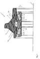
- FIG. 1 shows a schematic longitudinal sectional view of a wheel bearing assembly 1, which allows the rotation of a wheel (not shown) about a rotation axis 2.
- the wheel bearing assembly 1 has a hub 3 and an inner ring assembly 4, which are rotatably mounted about the rotation axis 2 to each other.
- the inner ring assembly 4 is fixed, for example, on a journal or the like (not shown).
- two rows of rolling elements 5 a, b are provided with tapered rollers which radially inward on two inner rings 6 a, b, which form part of the inner ring assembly 4, and radially outside on two outer rings 7 a, b, which are pressed into the hub 3, roll off.
- the rows of rolling elements 5 a, b are arranged at a distance from one another, so that an inner space 8 results between them, in which a grease distributor ring 9 is arranged.
- the grease distributor ring 9 is designed to support the distribution of grease from a grease depot 10, which is arranged on the inner rings 6 a, b, in the region of the inner space 8.
- the lubricating grease of the grease depot 10 is distributed along the radial outer side of the inner rings 6 a, b, so that the lubricating grease is fed to the rolling element rows 5 a, b.
- grease from the grease depot 10 is often also separated from the inner rings 6 a, b by heat or vibrations and would be deposited in a dead zone 11 of the inner space 8 without the grease distributor ring 9.
- FIG. 2 shows, which is an enlarged detail of the wheel bearing assembly 1 in the area of the grease distribution ring 9, the grease distributor ring 9 ensures that grease from the grease depot 10, which is dropped radially outward, is collected by the grease distributor ring 9 and in the direction of the rolling body rows 5 a, b is transported further.
- the grease distribution ring 9 in the FIG. 1 or 2 has a central portion 12, where two fat guide surfaces 13 a, b connect.
- the course of the fat distribution surfaces 13 a, b is in the longitudinal section shown, starting from the central portion 12 to the axial end faces of the grease distribution ring 9 monotonous and - in this example - even strictly monotonous and steadily increasing.
- the grease which is collected by the grease distribution surfaces 13 a, b, guided by the centrifugal force along the fat distribution surfaces 13 a, b in the axial direction and - again from the FIG. 1 results - delivered to the rolling elements of the rows of rolling elements 5 a, b.
- the free distance between central portion 12 and inner ring assembly 4 is small, for example chosen in the order of less than 3 mm.
- the central portion 12 may be radially inward as in the FIG. 2 shown, be formed horizontally, in alternative embodiments, the area can also be realized convex convex in the direction of the axis of rotation 2.
- the outlet 14 a, b of the fat distribution surfaces 13 a, b is dimensioned in the radial height so that the grease guide surfaces 13 a, b either in the top of the adjacent outer ring 7 a and 7 b overflow without obstruction or even radially offset inwardly ,
- the grease distribution ring 9 is between the outer rings 7 a, b frictionally and / or clamped and / or positively secured, so that it is carried along with the hub 3 during rotation.
- the outer rings 7 a, b are pressed from the outside axially into the hub 3 and rest there on shoulders 15 a, b.
- the grease distribution ring 9 is preferably formed as a plastic part, which is produced for example by injection molding. It can also be used glass fiber reinforced plastic.
- a possible structural design of the grease distribution ring 9 is in the FIG. 3 shown, which also represents a longitudinal section through the rotation axis 2.
- the grease distribution ring 9 is realized in a hollow design. On the one hand, material costs are saved in such an embodiment, on the other hand, the mass moved along with the hub 3 is reduced. Also in the FIG. 3 the grease distribution ring over a central portion 12 and two fat distribution surfaces 13 a, b constructed.
- a notable advantage of the wheel bearing assembly 1 lies in the ease of assembly or disassembly of the structure.
- the grease distribution ring 9 can be inserted in a first step and then in a second step, the outer rings 7 a, b are pressed.
- disassembling the grease distribution ring 9 seems initially to bother because it hinders access to the outer rings 7a, b for squeezing.
- the grease distribution ring 9 is constructed of plastic and - as will be explained below - can have predetermined breaking points, this can be removed destructively in a simple manner, so that again enough space for pressing the outer rings 7 a, b is available.
- FIGS. 4a-4g each show in a schematic longitudinal sectional view of various embodiments of the grease distribution ring 9. Although the embodiments are each shown as solid formations, but they can in an analogous manner to the FIG. 3 be made with a reduced cost of materials as a hollow design.
- FIG. 4a shows a symmetrical embodiment, wherein the grease guide surfaces 13 a, b are each arranged mirror-symmetrically to a radial plane perpendicular to the axis of rotation 2.
- FIG. 4b shows an embodiment with a flatter curvature of the fat distribution surfaces 13 a, b in comparison to the figure a, whereby a weaker conveying effect and a larger fat chamber can be achieved radially below the grease distributor ring 9.
- the Figure 4c shows a version with a steeper curvature than in the FIG. 4a , whereby a stronger conveying effect is achieved and also the grease reservoir 10 is positioned even closer to the rolling element rows 5 a, b.
- FIG. 4d shows a modified embodiment with Fettmengenbe dictionary, 9 disks 16 are integrally formed on the front side of the grease distribution ring, which limit the space 17 a, 16 b between the grease distribution surfaces 13 a and 13 b and the inner rings 6 a, 6 b in the axial direction.
- a plurality of grease passage holes 18 are distributed in the circulation direction, and the size, number and distribution of the grease passage holes 18 regulate the discharge amount.
- the Figure 4e shows an asymmetrical embodiment of the grease distribution ring 9, wherein the left fat distribution surface 13 a in the sectional plane has a greater axial extent than the right fat distribution surface 13 b. Due to the different dimensions, the curvatures in the longitudinal section shown are different. With such an embodiment, it is possible, for example, on the in FIG. 4 e right side with the larger curvature to achieve a stronger conveying effect and to realize a weaker conveying effect on the left side, but with a larger fat chamber. It is conceivable, this asymmetric To maintain distribution over the circumference constant.
- An alternative, however, is to distribute flat and steep fat distribution surface sections alternately in the circumferential direction. Thus, for example, in the FIG. 4 e in the sectional plane a flat design of the fat distribution surface 13 a and in the background a steep design of the distribution surface 13 a.
- the fat distribution surface 13 b may be formed alternately in an analogous manner.
- FIG. 4f shows a combination of the embodiments of Figure 4 d and 4 e , wherein the grease distributor ring 9 has both alternating areas in the circumferential direction and disks 16 with grease through holes 18.
- the fat passage holes 18 may not necessarily be distributed equidistant in the direction of rotation, or always have the same size. Analogous to alternating embodiments of the curvature in the fat distribution surfaces 13 a or 13 b, areas with different fat discharge characteristics can also be generated via the grease passage holes 18 in the direction of rotation.
- the Figure 4g shows a further embodiment, wherein the surfaces of the fat distribution surfaces 13 a and b have longitudinally or transversely grilled structures, in addition to provide for a delayed or accelerated release of the grease.
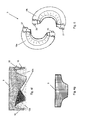
- FIG. 5 shows a schematic three-dimensional representation of the grease distribution ring 9 in a possible embodiment, wherein the grease distribution ring 9 is interrupted twice in the direction of rotation, so that two identically shaped halves 19 a, b of the grease distribution ring 9 are formed.
- these two halves on retaining lugs 20 and grooves 21, which are arranged at the free ends of the halves 19 a, b, are assembled in a simple manner.
- the interface between the two halves 19 a, b also serves as a disassembly aid or as a predetermined breaking point, for example, in the case of repairing a bearing damage.
- FIGS. 6a, b, c show a second optional embodiment for dividing the grease distribution ring 9, this embodiment - as shown in the FIG. 6 a is shown, which is the representation of FIG. 3 is divided along the section line A - A.
- the FIG. 6b shows a plan view illustrating the detail B, which in the FIG. 6c is shown schematically.
- This interface can also be used as a predetermined breaking point during disassembly.
Landscapes
- Engineering & Computer Science (AREA)
- General Engineering & Computer Science (AREA)
- Mechanical Engineering (AREA)
- Rolling Contact Bearings (AREA)
Description
- Die Erfindung betrifft eine Radlageranordnung mit einem drehenden und einem stationären Drehpartner und mit mindestens zwei Wälzkörperreihen, wobei die Drehpartner um die zwei Wälzkörperreihen zueinander drehbar um eine Drehachse gelagert sind, und mit einem Fettverteilerring, wobei der Fettverteilerring drehfest mit dem drehenden Drehpartner verbunden ist und eine erste Fettführungsfläche aufweist, welche so ausgerichtet ist, dass bei der Rotation des drehenden Drehpartners Schmiermittel an eine der Wälzkörperreihen geleitet wird.
- Radlageranordnungen dienen im allgemeinen dazu, angetriebene oder nicht angetriebene Räder eines Fahrzeugs drehbar zu lagern. Nachdem aufgrund von Qualitätsansprüchen von Anwendern gefordert wird, dass Radlageranordnungen über mehrere 100-Tausende oder Millionen Kilometer versagensfrei in dem Fahrzeug arbeiten, ist es notwendig, eine zuverlässige Dauerschmierung für die Radlageranordnung, insbesondere für die Wälzkörper der Wälzkörperreihen vorzusehen.
- Hierzu ist es bei zweireihigen Radlageranordnungen bekannt, den Zwischenraum zwischen den Wälzkörperreihen mit Schmierfett zu versehen und auf diese Weise eine Lebensdauerschmierung zu erreichen. Eine derartige Lösung wird beispielsweise in der Druckschrift
WO 2004/099637 A 1 vorgeschlagen. - Bei einer anderen Ausführung gemäß der Druckschrift
US 2005/0185871 A1 , die ebenfalls eine Radlageranordnung beschreibt, wird vorgeschlagen durch Aussparungen, welche in einem äußeren Drehpartner und/oder in einem inneren Drehpartner eingebracht sind, den Bereich zwischen den beiden Wälzkörperreihen zu vergrößern und auf diese Weise mehr Freiraum für zusätzliches Schmierfett bereit zu stellen. - Die Druckschrift
US 3,913,992 beschreibt ein verbessertes Schmierverfahren für eine Lageranordnung, bei der eine Nabe auf einem Zapfen über ein zweireihiges Wälzlager gelagert ist. Bei einer Ausführungsform ist jedem der Wälzkörperreihen ein separater Fettverteilerring zugeordnet, welcher drehfest mit der Nabe verbunden ist und mit dieser rotiert. Jeder Fettverteilerring weist im Längsschnitt durch die Drehachse auf der der Wälzkörperreihe zugewandten Seite einen derart gekrümmten Verlauf auf, so dass Schmierfett, welches im Bereich der Krümmung eingebracht ist, im Betrieb durch die Zentrifugalkraft den Fettverteilerring entlang kriecht und zu den Wälzkörpern geleitet wird. - Aus
JP 2000192972 A - In der
JP 2008095766 A - Der Erfindung liegt die Aufgabe zu Grunde, eine Radlageranordnung mit einer zuverlässigen Schmierung vorzuschlagen, welche sich durch einen einfachen Aufbau auszeichnet.
- Diese Aufgabe wird durch eine Radlageranordnung mit den Merkmalen des Anspruchs 1 gelöst. Bevorzugte oder vorteilhafte Ausführungsformen der Erfindung ergeben sich aus den Unteransprüchen, der nachfolgenden Beschreibung und den beigefügten Figuren.
- Im Rahmen der Erfindung wird eine Radlageranordnung für ein beliebiges Fahrzeug, insbesondere für ein Auto, bevorzugt für einen Lastkraftwagen, vorgeschlagen, welche einen drehenden und einen stationären Drehpartner aufweist. Bevorzugt ist der stationäre Drehpartner als ein Achszapfen oder dergleichen ausgebildet, der drehende Drehpartner bildet einen Träger für eine Nabe oder ist selbst als die Nabe ausgebildet.
- Die Radlageranordnung weist mindestens zwei Wälzkörperreihen mit Wälzkörpern auf, wobei die Drehpartner über die zwei Wälzkörperreihen zueinander drehbar um eine gemeinsame Drehachse gelagert sind. Die Wälzkörper sind in der allgemeinsten Ausführung beliebig ausgebildet. Insbesondere bei einem Einsatz bei einem Lastkraftwagen ist es bevorzugt, dass die Wälzkörper als Rollen, insbesondere Zylinderrollen, Kegelrollen oder Tonnen realisiert sind. Die Wälzkörper können auch als Kugeln oder Kugelrollen ausgebildet sein. Vorzugsweise sind die Wälzkörper der zwei Wälzkörperreihen zueinander in einer O-Anordnung arrangiert.
- Die Radlageranordnung umfasst im Weiteren einen Fettverteilerring, welcher drehfest mit dem drehenden Partner verbunden ist und mit diesem rotiert. Der Fettverteilerring weist eine erste Fettführungsfläche auf, welche so ausgerichtet ist, dass bei der Rotation des drehenden Drehpartners und somit bei der Rotation des Fettverteilerrings Schmierfett, welches auf dem Fettverteilerring angeordnet bzw. gelangt ist, an eine der Wälzkörperreihen geleitet wird.
- Zudem weist der Fettverteilerring eine zweite Fettführungsfläche auf, welche so ausgerichtet ist, dass bei der Rotation des drehenden Drehpartners Schmierfett auch an die andere der Wälzkörperreihen geleitet wird.
- Damit wird gemäß der Erfindung vorgeschlagen, den Fettverteilerring als eine zentral zwischen zwei Wälzkörperreihen angeordnete Baueinheit oder - gruppe auszubilden, welche zum einen einfach herstellbar ist und zum anderen in einfacher Weise montiert bzw. demontiert werden kann. Der Vorteil des zentralen Fettverteilerrings ist auch darin zu sehen, dass der Zwischenraum zwischen den beiden Wälzkörperreihen, welcher bereits oftmals für ein Schmierfettdepot genutzt wird, weiterhin verwendet werden kann. Im Gegensatz zu den bekannten Lösungen, bei denen das Schmierfett des Schmierfettdepots aufgrund von Wärmeeinwirkung, insbesondere zu starker Hitze, und/oder Vibrationen gegen die Nabe geschleudert wird und durch die Zentrifugalkraft des drehenden Drehpartners, also der Nabe, dort festgehalten wird, sorgt der Fettverteilerring dafür, dass Schmierfett, welches den stationären Drehpartner verlässt, aufgefangen und zuverlässig zu den Wälzkörperreihen geführt wird. Dadurch ist sichergestellt, dass nahezu das gesamte Schmierfettdepot zur Nachversorgung der Wälzkörperreihen verwendet wird und nicht in einem toten Raum der Radlageranordnung abgelegt wird.
- Die Erfindung schlägt vor, dass die beiden Fettführungsflächen in dem Längsschnitt unterschiedliche Krümmungen, unterschiedliche axiale Erstreckungen und/oder unterschiedliche radiale Erstreckungen aufweisen. Durch die genannten Parameter ist es möglich, die Schmierfetttransportgeschwindigkeit und das verfügbare Schmierfettvolumen kontrolliert einzustellen und auf diese Weise die Schmierfettzufuhr zu den Wälzkörperreihen zu steuern.
- Bei einer besonders bevorzugten Ausführungsform der Erfindung wird das Schmierfettdepot auf dem stationären Drehpartner angeordnet, wobei ein Weg des Schmierfetts zu den Wälzkörperreihen über das Kriechen des Schmierfetts entlang des stationären Drehpartners erfolgt. Nur der durch Hitzeentwicklung oder Vibration etc. auf den rotierenden Drehpartner bzw. auf den Fettverteilerring übertragene Anteil des Schmierfettes wird über die Fettführungsflächen an die Wälzkörper weitergeführt, so dass ein zweiter Weg gebildet ist. Bevorzugt ist zwischen den beiden Fettführungsflächen ein Mittelabschnitt angeordnet, welcher im Längsschnitt konzentrisch oder konvex bzw. gewölbt zu der Drehachse hin ausgebildet ist. Dieser Mittelabschnitt kann Kontakt mit dem auf dem stationären Drehpartner angeordneten Fettdepot aufnehmen und so das Schmierfett aktiv an den Fettverteilerring übertragen.
- Bei einer weiteren bevorzugten Ausführungsform der Erfindung ist der Fettverteilerring aus einem Kunststoffmaterial und/oder als Spritzgussteil ausgebildet. Zum einen führt die Materialwahl dazu, dass die ungefederte, drehende Masse der Radlageranordnung nur geringfügig erhöht wird, zum anderen erlaubt die Ausbildung aus einem Kunststoffmaterial, dass bei einer Demontage der Fettverteilerring in einfacher Weise aus der Radlageranordnung herausgebrochen werden kann. Bevorzugt weist der Fettverteilerring mindestens eine Sollbruchstelle auf, um das Herausbrechen bzw. Demontieren des Fettverteilerrings zu erleichtern.
- Bei einer möglichen Ausführungsform der Erfindung ist der Fettverteilerring einteilig bzw. einstückig ausgebildet. Es ist jedoch mehr bevorzugt, wenn der Fettverteilerring mehrteilig ausgebildet ist, da zum einen die Fertigung kostengünstiger ist und zum anderem die Montage bzw. Demontage vereinfacht wird. Besonders bevorzugt ist der Fettverteilerring in Umlaufrichtung und/oder in axialer Richtung ein- oder mehrfach geteilt. Bei einer ersten möglichen Ausführungsform ist der Fettverteilerring beispielsweise in Umlaufrichtung so geteilt, dass dieser zweimal unterbrochen ist, wobei die zwei Hälften des Fettverteilerrings bevorzugt identisch ausgebildet sind und z.B. über Haltenasen und Nuten miteinander verbunden werden. Bei einer anderen möglichen Ausführungsform ist der Fettverteilerring in axialer Richtung einfach unterbrochen, auch hier sind vorzugsweise die beiden Hälften identisch ausgebildet und weisen beispielsweise Nasen auf, welche bei der Montage ineinander greifen.
- Bei einer bevorzugten Ausführungsform der Erfindung zeigen die erste und/oder die zweite Fettführungsfläche in einem Längsschnitt durch die Drehachse einen gekrümmten Kurvenverlauf, welcher sich vorzugsweise monoton, insbesondere streng monoton von einem bzw. dem Mittelabschnitt in Richtung der Wälzkörper der Wälzkörperreihen erstreckt. Durch die monoton steigende Ausprägung des Kurvenverlaufs ist sichergestellt, dass sich keine toten Räume für das Schmierfett ergeben.
- In einer praxisnahen Ausführung ist sichergestellt, dass der Auslauf der Fettführungsfläche oder -flächen im Bereich der Wälzkörperreihen so angeordnet ist, dass das Schmierfett ungehindert zu den Wälzkörperreihen übertreten kann. Dabei ist es bevorzugt, dass der Auslauf in radial der gleichen Höhe bzw. radial nach innen versetzt zu der radialen Außenseite der Wälzkörperreihe an der dem Fettverteilerring zugewandten Ende angeordnet ist.
- Bei einer besonders bevorzugten Ausführungsform der Erfindung ist die Geometrie der Fettführungsfläche auf mindestens einer Seite des Fettverteilerrings in Umlaufrichtung nicht konstant, sondern variierend ausgebildet, wobei sich die Variation auf die oben genannten Parameter erstrecken kann. Durch diese Modifikation ist es möglich, in Umlaufrichtung auf der Seite des Fettverteilerrings mit variierender Geometrie Bereiche mit unterschiedlichen Fettzuführungseigenschaften einzurichten, so dass beispielsweise ein Bereich mit einer geringen Fettzuführungsgeschwindigkeit neben einem Bereich mit einer hohen Fettzuführungsgeschwindigkeit angeordnet ist.
- Als eine weitere Möglichkeit zur Steuerung der Schmierfettgeschwindigkeit auf den Fettführungsflächen kann diese Strukturen, insbesondere Längs- und/oder Querrillen und/oder Spiralrillen und/oder Schägrillen aufweisen. Während die Längsrillen in axialer Richtung eher die Schmierfettgeschwindigkeit erhöhen, wird das Fortschreiten des Schmierfettes durch dazu senkrechte Querrillen verringert. Bevorzugt ist auch eine spiralförmige und/oder schneckenförmige und/oder schraubenförmige Anordnung oder Ausprägung der Rillen. Sie hat zur Folge, dass durch die Zentrifugalkraft das Fett in Richtung Lagerstelle gefördert wird, es aber gleichzeitig zu der gewünschten Verzögerung kommt, da das Fett den längeren Weg der Spirale etc. gehen muss. Über die Steigung der Spirale und der Umfangsgeschwindigkeit wird die Fettfördergeschwindigkeit eingestellt. Über die Tiefe der Rillen kann eingestellt werden, wie viel Fett über die Spirale zum Lager geführt wird und wie viel über die Rillen hinweg sich direkt zum Lager bewegt. Neben einer Rillenstruktur können auch andere Strukturen eingebracht werden, die funktionell betrachtet den gleichen oder einen ähnlichen Effekt zeigen.
- Bei einer Weiterbildung der Erfindung weist der Fettverteilerring an mindestens einer Seite eine umlaufende Scheibe auf, welche bevorzugt einstückig und/oder einmaterialig in dem Fettverteilerring angeordnet ist, und den durch die Fettführungsfläche aufgespannten Raum in axialer Richtung begrenzt. Die Scheibe weist Fettdurchgangslöcher auf, welche als Fettmengenbegrenzer wirken. Bei dieser Weiterbildung wird das Schmierfett durch die Zentrifugalkraft entlang der Fettführungsfläche bzw. -flächen in Richtung der Wälzkörperreihen transportiert, legt sich dann an der oder den Scheiben an und wird begrenzt durch die Fettdurchgangslöcher an die Wälzkörperreihen abgegeben.
- Konstruktiv betrachtet ist es bevorzugt, dass die Radlageranordnung zwei Außenringe mit Laufbahnen aufweist, welche von einander beabstandet angeordnet sind, wobei der Fettverteilerring zwischen den Außenringen kraftschlüssig oder geklemmt gehalten und/oder formschlüssig fixiert ist. Diese Ausbildung weist den Vorteil auf, dass der Innenraum zwischen den Wälzkörperreihen durch das Zusammenfahren der zwei Außenringe und die Anlage an den Fettverteilerring nach radial außen eine statische Dichtheit aufweist. Bevorzugt werden die Außenringe jeweils von axial außen in den im nachfolgenden Betrieb drehenden Drehpartner eingepresst und liegen dort jeweils an einer Schulter des drehenden Drehpartners an. Der Fettverteilerring ist zwischen den inneren Stirnseiten der Außenringe festgeklemmt. Ein Vorteil dieser Anordnung ist es, dass bei einer Demontage der Radlageranordnung zunächst der Fettverteilerring zerstörend, beispielsweise durch Aufbrechen an Sollbruchstellen oder an den Fügestellen bei mehrteiliger Ausführung, ausgebaut werden kann und in einem nächsten Schritt - nachdem die inneren Stirnseiten der Außenringe nun zugänglich sind - die Außenringe ausgepresst werden können. Bei dem Zusammenbau wird in umgekehrter Reihenfolge verfahren, hier wird zuerst der Fettverteilerring eingesetzt und dann von beiden Seiten die Außenringe eingepresst.
- Es ist ebenfalls bevorzugt, wenn die Radlageranordnung zwei Innenringe mit Laufbahnen für die Wälzkörperreihen aufweist, wobei die Innenringe unmittelbar an einer Stoßstelle aneinander stoßen und/oder über einen Klammerring miteinander verbunden sind. Bevorzugt ist die Stoßstelle der zwei Innenringe in radialer Richtung mit dem Fettverteilerring überlappend angeordnet.
- Weitere Merkmale, Vorteile und Wirkungen der Erfindung ergeben sich aus der nachfolgenden Beschreibung bevorzugter Ausführungsbeispiele sowie der beigefügten Figuren. Dabei zeigen:
- Fig 1
- eine schematische Längsschnittdarstellung einer Radlageranordnung gemäß dem Stand der Technik;
- Fig 2
- einen Detailausschnitt aus der
Figur 1 zur Illustration der Funktionsweise des Fettverteilerrings gemäß dem Stand der Technik; - Fig 3
- eine schematische Längsschnittdarstellung des Fettverteilerrings in einer möglichen Ausführungsform der
Figuren 1 und2 gemäß dem Stand der Technik; - Fig 4 a - d und Fig 4g
- verschiedene Varianten hinsichtlich der Geometrie, des Materials, der Oberflächenstruktur und des konstruktiven Aufbaus des Fettverteilerrings in den vorhergehenden Figuren gemäß dem Stand der Technik;
- Fig 4 e - f
- verschiedene Varianten hinsichtlich der Geometrie, des Materials, der Oberflächenstruktur und des konstruktiven Aufbaus des Fettverteilerrings gemäß der Erfindung;
- Fig 5
- eine schematische dreidimensionale Skizze eines Fettverteilerrings zur Illustration eines möglichen mehrteiligen Aufbaus gemäß dem Stand der Technik;
- Fig 6 a - c
- schematische Darstellungen einer weiteren Möglichkeit für einen mehrteiligen Aufbau des Fettverteilerrings der vorhergehenden Figuren gemäß dem Stand der Technik.
- Einander entsprechende oder gleiche Größen bzw. Teile sind mit einander entsprechenden oder gleichen Bezugszeichen versehen.
-
Figur 1 zeigt in einer schematischen Längsschnittdarstellung eine Radlageranordnung 1, welche die Drehung eines Rades (nicht gezeigt) um eine Drehachse 2 ermöglicht. Die Radlageranordnung 1 weist eine Nabe 3 und eine Innenringanordnung 4 auf, welche um die Drehachse 2 zueinander drehbar gelagert sind. Die Innenringanordnung 4 wird beispielsweise auf einem Achszapfen oder dergleichen (nicht gezeigt) befestigt. - Zur Umsetzung der Rotation der Nabe 3 um die Innenringanordnung 4 sind zwei Wälzkörperreihen 5 a, b mit Kegelrollen vorgesehen, welche radial innen auf zwei Innenringen 6 a, b, die einen Teil der Innenringanordnung 4 bilden, und radial außenseitig auf zwei Außenringen 7 a, b, welche in die Nabe 3 eingepresst sind, abwälzen. Die Wälzkörperreihen 5 a, b, sind zueinander beabstandet angeordnet, so dass sich zwischen diesen ein Innenraum 8 ergibt, in dem ein Fettverteilerring 9 angeordnet ist.
- Der Fettverteilerring 9 ist dazu ausgebildet, die Verteilung von Schmierfett aus einem Schmierfettdepot 10, welches auf den Innenringen 6 a, b, im Bereich des Innenraums 8 angeordnet ist, zu unterstützen. Zum einen verteilt sich das Schmierfett des Schmierfettdepots 10 entlang der radialen Außenseite der Innenringe 6 a, b, so dass das Schmierfett den Wälzkörperreihen 5 a, b, zugeführt wird. Zum anderen wird Schmierfett von dem Schmierfettdepot 10 auch oftmals durch Hitzeeinwirkungen oder Vibrationen von den Innenringen 6 a, b, getrennt und würde - ohne den Fettverteilerring 9 - in einem toten Bereich 11 des Innenraums 8 abgelagert werden. Nachdem sich die Nabe 3 im Betrieb dreht, wohingegen die Innenringanordnung 4 stationär verbleibt, würde Schmierstoff, welcher in dem toten Raum 11 angelagert ist, durch die Zentrifugalkraft dort dauerhaft fixiert werden und wäre für die weitere Schmierung verloren.
- Wie sich insbesondere aus der
Figur 2 ergibt, welche eine Ausschnittvergrößerung der Radlageranordnung 1 im Bereich des Fettverteilerrings 9 ist, sorgt der Fettverteilerring 9 dafür, dass Schmierfett aus dem Schmierfettdepot 10, welches radial nach außen abgeworfen wird, von dem Fettverteilerring 9 aufgefangen wird und in Richtung der Wälzkörperreihen 5 a, b weitertransportiert wird. - Der Fettverteilerring 9 in der
Figur 1 bzw. 2 weist einen Mittelabschnitt 12 auf, an denen sich zwei Fettführungsflächen 13 a, b anschließen. Der Verlauf der Fettverteilungsflächen 13 a, b ist in dem gezeigten Längsschnitt ausgehend von dem Mittelabschnitt 12 zu den axialen Stirnflächen des Fettverteilerrings 9 monoton und - in diesem Beispiel - sogar streng monoton und stetig steigend ausgebildet. Durch diesen Verlauf wird das Schmierfett, welches von den Fettverteilungsflächen 13 a, b aufgefangen wird, durch die Zentrifugalkraft entlang der Fettverteilungsflächen 13 a, b in axialer Richtung geführt und - wie sich wiederum aus derFigur 1 ergibt - an die Wälzkörper der Wälzkörperreihen 5 a, b abgegeben. - Der freie Abstand zwischen Mittelabschnitt 12 und Innenringanordnung 4 ist gering, zum Beispiel in der Größenordnung von kleiner 3 mm gewählt. Der Mittelabschnitt 12 kann radial innen wie in der
Figur 2 gezeigt, waagrecht ausgebildet sein, bei alternativen Ausführungsformen kann der Bereich auch konvex in Richtung der Drehachse 2 ausgewölbt realisiert sein. Der Auslauf 14 a, b der Fettverteilungsflächen 13 a, b ist in der radialen Höhe so bemessen, dass die Fettführungsflächen 13 a, b entweder in die Oberseite des angrenzenden Außenrings 7 a bzw. 7b ohne Hindernis überlaufen oder sogar radial versetzt nach innen angeordnet sind. - Wie sich wieder aus der
Figur 1 ergibt, ist der Fettverteilerring 9 zwischen den Außenringen 7 a, b kraftschlüssig und/oder klemmend und/oder formschlüssig befestigt, so dass dieser mit der Nabe 3 bei einer Drehung mitgeführt wird. Die Außenringe 7 a, b sind von axial außen in die Nabe 3 eingepresst und liegen dort an Schultern 15 a, b an. - Der Fettverteilerring 9 ist bevorzugt als ein Kunststoffteil ausgebildet, welches beispielsweise in Spritzgusstechnik hergestellt wird. Es kann auch glasfaserverstärkter Kunststoff eingesetzt werden. Eine mögliche konstruktive Gestaltung des Fettverteilerrings 9 ist in der
Figur 3 gezeigt, die ebenfalls einen Längsschnitt durch die Drehachse 2 darstellt. Der Fettverteilerring 9 ist in einer hohlen Ausführung realisiert. Zum einen werden bei einer derartigen Ausführungsform Materialkosten eingespart, zum anderen wird die mit der Nabe 3 mitbewegte Masse verringert. Auch in derFigur 3 ist der Fettverteilerring über einen Mittelabschnitt 12 und zwei Fettverteilungsflächen 13 a, b aufgebaut. - Ein bemerkenswerter Vorteil der Radlageranordnung 1 liegt in der Montage bzw. Demontagefreundlichkeit des Aufbaus. Bei der Montage der Radlageranordnung 1 kann in einem ersten Schritt der Fettverteilerring 9 eingelegt werden und dann in einem zweiten Schritt die Außenringe 7 a, b eingepresst werden. Bei der Demontage scheint der Fettverteilerring 9 zunächst zu stören, da er den Zugriff auf die Außenringe 7a,b zum Auspressen behindert. Nachdem der Fettverteilerring 9 jedoch aus Kunststoff aufgebaut ist und - wie nachfolgend noch erläutert wird - Sollbruchstellen aufweisen kann, kann dieser in einfacher Weise zerstörend ausgebaut werden, so dass wieder ausreichend Platz für ein Auspressen der Außenringe 7 a, b zur Verfügung steht.
- Die
Figuren 4a - 4g zeigen jeweils in einer schematischen Längsschnittansicht verschiedene Ausführungsformen des Fettverteilerrings 9. Obwohl die Ausführungsformen jeweils als Massivausbildungen dargestellt sind, können diese jedoch in analoger Weise zu derFigur 3 mit einem verringerten Materialaufwand als eine hohle Ausführung hergestellt werden. - Die
Figur 4a zeigt eine symmetrische Ausführungsform, wobei die Fettführungsflächen 13 a, b jeweils spiegelsymmetrisch zu einer Radialebene senkrecht zu der Drehachse 2 angeordnet sind. - Die
Figur 4b zeigt eine Ausführungsform mit einer flacheren Krümmung der Fettverteilungsflächen 13 a, b im Vergleich zu der Figur a, wodurch eine schwächere Förderwirkung und eine größere Fettkammer radial unterhalb des Fettverteilerrings 9 erreicht werden kann. - Die
Figur 4c zeigt dagegen eine Ausführung mit einer steileren Krümmung als in derFigur 4a , wodurch eine stärkere Förderwirkung erreicht wird und zudem das Schmierfettdepot 10 noch näher an deren Wälzkörperreihen 5 a, b positioniert ist. - Die
Figur 4d zeigt eine abgewandelte Ausführungsform mit Fettmengenbegrenzer, wobei an der Stirnseite des Fettverteilerrings 9 Scheiben 16 einstückig angeformt sind, welche den Raum 17 a, 16 b zwischen den Fettverteilungsflächen 13 a bzw. 13 b und den Innenringen 6 a, 6 b in axialer Richtung begrenzen. Zur Ausgabe von Schmierfett durch die Scheiben 16 ist eine Mehrzahl von Fettdurchgangslöchern 18 in Umlaufrichtung verteilt, wobei die Größe, Anzahl und Verteilung der Fettdurchgangslöcher 18 die Abgabemenge reguliert. - Die
Figur 4e zeigt eine asymmetrische Ausführungsform des Fettverteilerrings 9, wobei die linke Fettverteilungsfläche 13 a in der Schnittebene eine größere axiale Ausdehnung aufweist als die rechte Fettverteilungsfläche 13 b. Aufgrund der unterschiedlichen Ausdehnungen sind auch die Krümmungen in dem gezeigten Längsschnitt unterschiedlich ausgeprägt. Mit einer derartigen Ausführungsform ist es beispielsweise möglich, auf der inFigur 4 e rechten Seite mit der größeren Krümmung eine stärkere Förderwirkung zu erreichen und auf der linken Seite eine schwächere Förderwirkung, jedoch mit einer größeren Fettkammer, zu realisieren. Es ist denkbar, diese asymmetrische Verteilung über den Umfang konstant beizubehalten. Eine Alternative ist es aber, in Umfangrichtung flache und steile Fettverteilungsflächenabschnitte alternierend zu verteilen. So zeigt sich beispielsweise in derFigur 4 e in der Schnittebene eine flache Ausführung der Fettverteilungsfläche 13 a und im Hintergrund eine steile Ausführung der Verteilungsfläche 13 a. Die Fettverteilungsfläche 13 b kann in analoger Weise alternierend ausgebildet sein. - Die
Figur 4f zeigt eine Kombination aus den Ausführungsformen derFigur 4 d und 4 e , wobei der Fettverteilerring 9 sowohl alternierende Bereiche in Umlaufrichtung als auch Scheiben 16 mit Fettdurchgangslöchern 18 aufweist. - Es ist darauf hinzuweisen, dass sowohl in der
Figur 4d als auch in derFigur 4 f die Fettdurchgangslöcher 18 nicht unbedingt äquidistant in Umlaufrichtung verteilt sein, oder stets die gleiche Größe aufweisen müssen. Analog zu alternierenden Ausführungsformen der Krümmung bei den Fettverteilungsflächen 13 a oder 13 b können auch über die Fettdurchgangslöcher 18 in Umlaufrichtung Bereiche mit unterschiedlicher Fettabgabecharakteristik erzeugt werden. - Die
Figur 4g zeigt eine weitere Ausführungsform, wobei die Oberflächen der Fettverteilungsflächen 13 a bzw. b längs oder quer gegrillte Strukturen aufweisen, um zusätzlich für eine verzögerte oder beschleunigte Abgabe des Schmierfettes zu sorgen. - Die
Figur 5 zeigt eine schematische dreidimensionale Darstellung des Fettverteilerrings 9 in einer möglichen Ausführungsform, wobei der Fettverteilerring 9 in Umlaufrichtung zweimal unterbrochen ist, so dass zwei identisch ausgebildete Hälften 19 a, b des Fettverteilerrings 9 gebildet werden. Bei der Montage können diese beiden Hälften über Haltenasen 20 und Nuten 21, welche an den freien Enden der Hälften 19 a, b angeordnet sind, in einfacher Weise zusammengefügt werden. Die Schnittstelle zwischen den beiden Hälften 19 a, b dient zugleich als Demontagehilfe oder als Sollbruchstelle, zum Beispiel im Fall der Reparatur eines Lagerschadens. - Die
Figuren 6a, b, c zeigen eine zweite optionale Ausführung zur Teilung des Fettverteilerrings 9, wobei diese Ausführungsform - wie es in derFigur 6 a gezeigt ist, die der Darstellung derFigur 3 entspricht, entlang der Schnittlinie A - A geteilt wird. DieFigur 6b zeigt eine Draufsicht zur Illustration des Details B, welches in derFigur 6c schematisch dargestellt wird. Zur Verbindung der beiden Hälften 19 a, b des Fettverteilerrings 9, weist jede Hälfte 19 a bzw. b im Bereich des Mittelabschnitts 12 Nasen 22 auf, die bei der Montage ineinander greifen, so dass der Fettverteilerring 9 gebildet wird. Auch diese Schnittstelle kann bei einer Demontage als Sollbruchstelle verwendet werden. -
- 1
- Radlageranordnung
- 2
- Drehachse
- 3
- Nabe
- 4
- Innenringanordnung
- 5 a, b
- Wälzkörperreihen
- 6 a, b
- Innenringe
- 7 a, b
- Außenringe
- 8
- Innenraum
- 9
- Fettverteilerring
- 10
- Schmierfettdepot
- 11
- toter Bereich
- 12
- Mittelabschnitt
- 13 a, b
- Fettführungsfläche
- 14 a, b
- Auslauf
- 15 a, b
- Schulter
- 16
- Scheibe
- 17 a, b
- Raum
- 18
- Fettdurchgangslöcher
- 19a
- Hälfte des Fettverteilerringes
- 19b
- Hälfte des Fettverteilerringes
- 20
- Haltenasen
- 21
- Nuten
- 22
- Nasen
Claims (14)
- Radlageranordnung (1) mit einem drehenden und einem stationären Drehpartner (3,4) und mit zwei Wälzkörperreihen (5a,b), wobei die Drehpartner (3,4) über die zwei Wälzkörperreihen (5a,b) zueinander um eine Drehachse (2) drehbar gelagert sind, mit einem Fettverteilerring (9), wobei der Fettverteilerring (9) drehfest mit dem drehenden Drehpartner (3) verbunden ist und eine erste Fettführungsfläche (13a) aufweist, welche so ausgerichtet ist, dass bei der Rotation des drehenden Drehpartners (3) Schmierfett an eine der Wälzkörperreihen (5a) geleitet wird, wobei der Fettverteilerring (9) eine zweite Fettführungsfläche (13b) aufweist, welche so ausgerichtet ist, dass bei der Rotation des drehenden Drehpartners (3) Schmierfett an die andere der Wälzkörperreihen (5b) geleitet wird, dadurch gekennzeichnet, dass die beiden Fettführungsflächen (13a,b) in dem Längsschnitt unterschiedliche Krümmungen, unterschiedliche axiale Erstreckungen und/oder unterschiedliche radiale Erstreckungen aufweisen.
- Radlageranordnung (1) nach Anspruch 1, dadurch gekennzeichnet, dass ein Krümmungsverlauf der Fettführungsfläche (13a,b) in einem Längsschnitt durch die Drehachse in Umlaufrichtung variierend ausgebildet ist.
- Radlageranordnung (1) nach Anspruch 1 oder 2, wobei die Fettführungsfläche (13a,b) Strukturen aufweist.
- Radlageranordnung (1) nach Anspruch 3, wobei die Strukturen der Fettführungsfläche (13a,b) eine oder mehrere Spiralrillen um die Drehachse zur Steuerung der Schmierfettgeschwindigkeit sind.
- Radlageranordnung (1) nach einem der vorhergehenden Ansprüche, wobei der Fettverteilerring (9) eine Sollbruchstelle aufweist, die eine einfache Demontage im Schadensfall ermöglicht.
- Radlageranordnung (1) nach einem der vorhergehenden Ansprüche, wobei der Fettverteilerring (9) aus einem Kunststoffmaterial ausgebildet ist.
- Radlageranordnung (1) nach einem der vorhergehenden Ansprüche, wobei der Fettverteilerring (9) einteilig ausgebildet ist.
- Radlageranordnung (1) nach einem der Ansprüche 1 bis 6, wobei der Fettverteilerring (9) mehrteilig ausgebildet ist.
- Radlageranordnung (1) nach Anspruch 8, wobei der Fettverteilerring (9) in Umlaufrichtung und/oder in axialer Richtung einfach oder mehrfach geteilt ist.
- Radlageranordnung (1) nach einem der vorhergehenden Ansprüche, wobei die erste und/oder die zweite Fettführungsfläche (13a,b) in einem Längsschnitt durch die Drehachse (2) einen gekrümmten Kurvenlauf aufweisen.
- Radlageranordnung (1) nach einem der vorhergehenden Ansprüche, wobei der Fettverteilerring (9) an mindestens einer Seite eine umlaufende Scheibe (16) mit Fettdurchgangslöchern (18) aufweist, welche als Fettmengenbegrenzer wirkt.
- Radlageranordnung (1) nach einem der vorhergehenden Ansprüche, gekennzeichnet durch zwei drehende Außenringe (7a,b) mit Laufbahnen für die Wälzkörperreihen (5a,b), wobei der Fettverteilerring (9) zwischen den Außenringen (7a,b) kraftschlüssig gehalten ist.
- Radlageranordnung (1) nach einem der vorhergehenden Ansprüche, gekennzeichnet durch zwei Innenringe (6a,b) mit Laufbahnen für die Wälzkörperreihen (5a,b), wobei die Innenringe (6a,b) unmittelbar an einer Stoßstelle aneinander stoßen und/oder über einen Klammerring miteinander verbunden sind.
- Radlageranordnung (1) nach Anspruch 13, wobei die zwei Innenringe (6a,b) stationär sind und die Stoßstelle der zwei Innenringe (6a,b) in der radialen Richtung mit dem Fettverteilerring (9) überlappt.
Applications Claiming Priority (2)
| Application Number | Priority Date | Filing Date | Title |
|---|---|---|---|
| DE102008025568A DE102008025568A1 (de) | 2008-05-28 | 2008-05-28 | Radlageranordnung mit Fettverteilerring |
| PCT/EP2009/054288 WO2009144075A1 (de) | 2008-05-28 | 2009-04-09 | Radlageranordnung mit fettverteilerring |
Publications (2)
| Publication Number | Publication Date |
|---|---|
| EP2286100A1 EP2286100A1 (de) | 2011-02-23 |
| EP2286100B1 true EP2286100B1 (de) | 2015-06-10 |
Family
ID=40751030
Family Applications (1)
| Application Number | Title | Priority Date | Filing Date |
|---|---|---|---|
| EP09753730.2A Not-in-force EP2286100B1 (de) | 2008-05-28 | 2009-04-09 | Radlageranordnung mit fettverteilerring |
Country Status (4)
| Country | Link |
|---|---|
| EP (1) | EP2286100B1 (de) |
| BR (1) | BRPI0912124B8 (de) |
| DE (1) | DE102008025568A1 (de) |
| WO (1) | WO2009144075A1 (de) |
Families Citing this family (8)
| Publication number | Priority date | Publication date | Assignee | Title |
|---|---|---|---|---|
| DE102015210242B4 (de) | 2015-06-03 | 2022-08-25 | Schaeffler Technologies AG & Co. KG | Radlageranordnung für ein Fahrzeug |
| DE102015210243A1 (de) | 2015-06-03 | 2016-12-08 | Schaeffler Technologies AG & Co. KG | Radlageranordnung für ein Fahrzeug |
| DE102015211934A1 (de) | 2015-06-26 | 2016-12-29 | Schaeffler Technologies AG & Co. KG | Radlageranordnung für ein Fahrzeug |
| DE102016118056B4 (de) * | 2016-09-23 | 2020-12-17 | Thyssenkrupp Ag | Wälzlager, Windkraftanlage mit einem Wälzlager und Verfahren zur Montage eines Wälzlagers |
| DE102017105523B4 (de) * | 2017-03-15 | 2020-02-27 | Saf-Holland Gmbh | Nabe |
| IT201700076753A1 (it) * | 2017-07-07 | 2019-01-07 | Skf Ab | Dispositivo trattenitore di grasso e dosatore di olio per una unità cuscinetto a rotolamento |
| DE102017128966B3 (de) | 2017-12-06 | 2019-04-18 | Schaeffler Technologies AG & Co. KG | Radlagereinheit mit einer Rotationsachse |
| IT202000009133A1 (it) * | 2020-04-28 | 2021-10-28 | Skf Ab | Dispositivo dosatore di grasso per cuscinetti a rotolamento |
Family Cites Families (6)
| Publication number | Priority date | Publication date | Assignee | Title |
|---|---|---|---|---|
| US2272757A (en) * | 1940-12-19 | 1942-02-10 | Gen Electric | Bearing and supporting structure |
| US3913992A (en) | 1972-04-26 | 1975-10-21 | Continental Oil Co | Extended bearing lubrication method and apparatus |
| JP2000192972A (ja) | 1998-12-24 | 2000-07-11 | Ntn Corp | 外輪回転用グリース潤滑円すいころ軸受 |
| SE525142C2 (sv) | 2003-05-12 | 2004-12-07 | Volvo Lastvagnar Ab | Lagerarrangemang och hjulaxelarrangemang för fordon |
| JP2005214300A (ja) | 2004-01-29 | 2005-08-11 | Ntn Corp | 車軸用軸受装置 |
| JP2008095766A (ja) | 2006-10-10 | 2008-04-24 | Ntn Corp | 車輪用軸受 |
-
2008
- 2008-05-28 DE DE102008025568A patent/DE102008025568A1/de not_active Withdrawn
-
2009
- 2009-04-09 WO PCT/EP2009/054288 patent/WO2009144075A1/de not_active Ceased
- 2009-04-09 EP EP09753730.2A patent/EP2286100B1/de not_active Not-in-force
- 2009-04-09 BR BRPI0912124A patent/BRPI0912124B8/pt not_active IP Right Cessation
Also Published As
| Publication number | Publication date |
|---|---|
| BRPI0912124B8 (pt) | 2020-08-04 |
| WO2009144075A1 (de) | 2009-12-03 |
| EP2286100A1 (de) | 2011-02-23 |
| BRPI0912124B1 (pt) | 2020-06-16 |
| DE102008025568A1 (de) | 2009-12-03 |
| BRPI0912124A2 (pt) | 2015-11-03 |
Similar Documents
| Publication | Publication Date | Title |
|---|---|---|
| EP2129925B1 (de) | Mehrteiliger axialkäfig für ein grosswälzlager | |
| EP2236846B1 (de) | Wälzlager | |
| EP2286100A1 (de) | Radlageranordnung mit fettverteilerring | |
| EP2473748A1 (de) | Käfig für ein wälzlager und wälzlager | |
| EP3332137B1 (de) | Schrägrollenlager sowie verfahren und vorrichtung zu dessen montage | |
| WO2008092415A1 (de) | Drehlageranordnung | |
| EP3332134B1 (de) | Schrägrollenlager sowie verfahren und vorrichtung zu dessen montage | |
| EP2478235B1 (de) | Kugelrollenlager | |
| EP1837536A2 (de) | Schrägrollenlager | |
| EP1853829A1 (de) | Hochgeschwindigkeitsloslager, insbesondere zur lagerung der hauptspindel einer werkzeugmaschine | |
| WO2011018491A1 (de) | Käfigsegment für einen kunststoffkäfig eines wälzlagers und wälzlager mit einem solchen käfigsegment | |
| DE102010007668A1 (de) | Getriebeelement für ein Spannungswellengetriebe, Nockenwellenversteller sowie Lenkkrafthilfe | |
| DE102007033905A1 (de) | Vollkugeliges Schrägkugellager | |
| DE102012207528B3 (de) | Wälzlager | |
| EP2431623A2 (de) | Toroidal-Rollenlager | |
| DE102011078713B4 (de) | Radlageranordnung | |
| DE102017110742A1 (de) | Zweireihiges Pendelrollenlager | |
| DE3611907C2 (de) | ||
| DE102017113457B4 (de) | Lenkkopflageranordnung für ein Zweirad zur drehbaren Lagerung einer Lenkwelle | |
| DE102006048079A1 (de) | Radialzylinderrollenlager | |
| DE102012022003B4 (de) | Wälzlager mit stark verlängerter Gebrauchsdauer | |
| DE102020130707B3 (de) | Rollenlager | |
| DE102009052179A1 (de) | Lagerungseinheit zur Aufnahme radialer und axialer Kräfte, Verfahren zum Messen des Axialspiels der Lagerringe einer Lagerungseinheit sowie Abpassscheibe | |
| WO2009049956A1 (de) | Lageranordnung zur aufnahme radialer und axialer belastungen | |
| DE102010006803A1 (de) | Kegelrollenlager und Verfahren zur Montage eines Kegelrollenlagers |
Legal Events
| Date | Code | Title | Description |
|---|---|---|---|
| PUAI | Public reference made under article 153(3) epc to a published international application that has entered the european phase |
Free format text: ORIGINAL CODE: 0009012 |
|
| 17P | Request for examination filed |
Effective date: 20101228 |
|
| AK | Designated contracting states |
Kind code of ref document: A1 Designated state(s): AT BE BG CH CY CZ DE DK EE ES FI FR GB GR HR HU IE IS IT LI LT LU LV MC MK MT NL NO PL PT RO SE SI SK TR |
|
| AX | Request for extension of the european patent |
Extension state: AL BA RS |
|
| DAX | Request for extension of the european patent (deleted) | ||
| RAP1 | Party data changed (applicant data changed or rights of an application transferred) |
Owner name: SCHAEFFLER TECHNOLOGIES AG & CO. KG |
|
| 17Q | First examination report despatched |
Effective date: 20120913 |
|
| RAP1 | Party data changed (applicant data changed or rights of an application transferred) |
Owner name: SCHAEFFLER TECHNOLOGIES GMBH & CO. KG |
|
| GRAP | Despatch of communication of intention to grant a patent |
Free format text: ORIGINAL CODE: EPIDOSNIGR1 |
|
| INTG | Intention to grant announced |
Effective date: 20141216 |
|
| RAP1 | Party data changed (applicant data changed or rights of an application transferred) |
Owner name: SCHAEFFLER TECHNOLOGIES AG & CO. KG |
|
| GRAS | Grant fee paid |
Free format text: ORIGINAL CODE: EPIDOSNIGR3 |
|
| GRAA | (expected) grant |
Free format text: ORIGINAL CODE: 0009210 |
|
| AK | Designated contracting states |
Kind code of ref document: B1 Designated state(s): AT BE BG CH CY CZ DE DK EE ES FI FR GB GR HR HU IE IS IT LI LT LU LV MC MK MT NL NO PL PT RO SE SI SK TR |
|
| REG | Reference to a national code |
Ref country code: GB Ref legal event code: FG4D Free format text: NOT ENGLISH |
|
| REG | Reference to a national code |
Ref country code: CH Ref legal event code: EP |
|
| REG | Reference to a national code |
Ref country code: AT Ref legal event code: REF Ref document number: 731040 Country of ref document: AT Kind code of ref document: T Effective date: 20150715 |
|
| REG | Reference to a national code |
Ref country code: DE Ref legal event code: R096 Ref document number: 502009011140 Country of ref document: DE |
|
| REG | Reference to a national code |
Ref country code: IE Ref legal event code: FG4D Free format text: LANGUAGE OF EP DOCUMENT: GERMAN |
|
| PG25 | Lapsed in a contracting state [announced via postgrant information from national office to epo] |
Ref country code: NO Free format text: LAPSE BECAUSE OF FAILURE TO SUBMIT A TRANSLATION OF THE DESCRIPTION OR TO PAY THE FEE WITHIN THE PRESCRIBED TIME-LIMIT Effective date: 20150910 Ref country code: LT Free format text: LAPSE BECAUSE OF FAILURE TO SUBMIT A TRANSLATION OF THE DESCRIPTION OR TO PAY THE FEE WITHIN THE PRESCRIBED TIME-LIMIT Effective date: 20150610 Ref country code: ES Free format text: LAPSE BECAUSE OF FAILURE TO SUBMIT A TRANSLATION OF THE DESCRIPTION OR TO PAY THE FEE WITHIN THE PRESCRIBED TIME-LIMIT Effective date: 20150610 Ref country code: FI Free format text: LAPSE BECAUSE OF FAILURE TO SUBMIT A TRANSLATION OF THE DESCRIPTION OR TO PAY THE FEE WITHIN THE PRESCRIBED TIME-LIMIT Effective date: 20150610 |
|
| REG | Reference to a national code |
Ref country code: NL Ref legal event code: MP Effective date: 20150610 |
|
| PG25 | Lapsed in a contracting state [announced via postgrant information from national office to epo] |
Ref country code: BG Free format text: LAPSE BECAUSE OF FAILURE TO SUBMIT A TRANSLATION OF THE DESCRIPTION OR TO PAY THE FEE WITHIN THE PRESCRIBED TIME-LIMIT Effective date: 20150910 Ref country code: LV Free format text: LAPSE BECAUSE OF FAILURE TO SUBMIT A TRANSLATION OF THE DESCRIPTION OR TO PAY THE FEE WITHIN THE PRESCRIBED TIME-LIMIT Effective date: 20150610 Ref country code: GR Free format text: LAPSE BECAUSE OF FAILURE TO SUBMIT A TRANSLATION OF THE DESCRIPTION OR TO PAY THE FEE WITHIN THE PRESCRIBED TIME-LIMIT Effective date: 20150911 |
|
| PG25 | Lapsed in a contracting state [announced via postgrant information from national office to epo] |
Ref country code: EE Free format text: LAPSE BECAUSE OF FAILURE TO SUBMIT A TRANSLATION OF THE DESCRIPTION OR TO PAY THE FEE WITHIN THE PRESCRIBED TIME-LIMIT Effective date: 20150610 |
|
| PG25 | Lapsed in a contracting state [announced via postgrant information from national office to epo] |
Ref country code: CZ Free format text: LAPSE BECAUSE OF FAILURE TO SUBMIT A TRANSLATION OF THE DESCRIPTION OR TO PAY THE FEE WITHIN THE PRESCRIBED TIME-LIMIT Effective date: 20150610 Ref country code: PL Free format text: LAPSE BECAUSE OF FAILURE TO SUBMIT A TRANSLATION OF THE DESCRIPTION OR TO PAY THE FEE WITHIN THE PRESCRIBED TIME-LIMIT Effective date: 20150610 Ref country code: SK Free format text: LAPSE BECAUSE OF FAILURE TO SUBMIT A TRANSLATION OF THE DESCRIPTION OR TO PAY THE FEE WITHIN THE PRESCRIBED TIME-LIMIT Effective date: 20150610 Ref country code: PT Free format text: LAPSE BECAUSE OF FAILURE TO SUBMIT A TRANSLATION OF THE DESCRIPTION OR TO PAY THE FEE WITHIN THE PRESCRIBED TIME-LIMIT Effective date: 20151012 Ref country code: IS Free format text: LAPSE BECAUSE OF FAILURE TO SUBMIT A TRANSLATION OF THE DESCRIPTION OR TO PAY THE FEE WITHIN THE PRESCRIBED TIME-LIMIT Effective date: 20151010 Ref country code: RO Free format text: LAPSE BECAUSE OF NON-PAYMENT OF DUE FEES Effective date: 20150610 |
|
| REG | Reference to a national code |
Ref country code: DE Ref legal event code: R097 Ref document number: 502009011140 Country of ref document: DE |
|
| PLBE | No opposition filed within time limit |
Free format text: ORIGINAL CODE: 0009261 |
|
| STAA | Information on the status of an ep patent application or granted ep patent |
Free format text: STATUS: NO OPPOSITION FILED WITHIN TIME LIMIT |
|
| PG25 | Lapsed in a contracting state [announced via postgrant information from national office to epo] |
Ref country code: IT Free format text: LAPSE BECAUSE OF FAILURE TO SUBMIT A TRANSLATION OF THE DESCRIPTION OR TO PAY THE FEE WITHIN THE PRESCRIBED TIME-LIMIT Effective date: 20150610 Ref country code: DK Free format text: LAPSE BECAUSE OF FAILURE TO SUBMIT A TRANSLATION OF THE DESCRIPTION OR TO PAY THE FEE WITHIN THE PRESCRIBED TIME-LIMIT Effective date: 20150610 |
|
| 26N | No opposition filed |
Effective date: 20160311 |
|
| PG25 | Lapsed in a contracting state [announced via postgrant information from national office to epo] |
Ref country code: SI Free format text: LAPSE BECAUSE OF FAILURE TO SUBMIT A TRANSLATION OF THE DESCRIPTION OR TO PAY THE FEE WITHIN THE PRESCRIBED TIME-LIMIT Effective date: 20150610 |
|
| PG25 | Lapsed in a contracting state [announced via postgrant information from national office to epo] |
Ref country code: BE Free format text: LAPSE BECAUSE OF NON-PAYMENT OF DUE FEES Effective date: 20160430 |
|
| REG | Reference to a national code |
Ref country code: CH Ref legal event code: PL |
|
| GBPC | Gb: european patent ceased through non-payment of renewal fee |
Effective date: 20160409 |
|
| PG25 | Lapsed in a contracting state [announced via postgrant information from national office to epo] |
Ref country code: LU Free format text: LAPSE BECAUSE OF FAILURE TO SUBMIT A TRANSLATION OF THE DESCRIPTION OR TO PAY THE FEE WITHIN THE PRESCRIBED TIME-LIMIT Effective date: 20160409 |
|
| REG | Reference to a national code |
Ref country code: IE Ref legal event code: MM4A |
|
| REG | Reference to a national code |
Ref country code: FR Ref legal event code: ST Effective date: 20161230 |
|
| PG25 | Lapsed in a contracting state [announced via postgrant information from national office to epo] |
Ref country code: GB Free format text: LAPSE BECAUSE OF NON-PAYMENT OF DUE FEES Effective date: 20160409 Ref country code: LI Free format text: LAPSE BECAUSE OF NON-PAYMENT OF DUE FEES Effective date: 20160430 Ref country code: CH Free format text: LAPSE BECAUSE OF NON-PAYMENT OF DUE FEES Effective date: 20160430 Ref country code: FR Free format text: LAPSE BECAUSE OF NON-PAYMENT OF DUE FEES Effective date: 20160502 |
|
| PG25 | Lapsed in a contracting state [announced via postgrant information from national office to epo] |
Ref country code: IE Free format text: LAPSE BECAUSE OF NON-PAYMENT OF DUE FEES Effective date: 20160409 |
|
| REG | Reference to a national code |
Ref country code: AT Ref legal event code: MM01 Ref document number: 731040 Country of ref document: AT Kind code of ref document: T Effective date: 20160409 |
|
| PG25 | Lapsed in a contracting state [announced via postgrant information from national office to epo] |
Ref country code: NL Free format text: LAPSE BECAUSE OF FAILURE TO SUBMIT A TRANSLATION OF THE DESCRIPTION OR TO PAY THE FEE WITHIN THE PRESCRIBED TIME-LIMIT Effective date: 20150610 Ref country code: SE Free format text: LAPSE BECAUSE OF FAILURE TO SUBMIT A TRANSLATION OF THE DESCRIPTION OR TO PAY THE FEE WITHIN THE PRESCRIBED TIME-LIMIT Effective date: 20150610 |
|
| PG25 | Lapsed in a contracting state [announced via postgrant information from national office to epo] |
Ref country code: AT Free format text: LAPSE BECAUSE OF NON-PAYMENT OF DUE FEES Effective date: 20160409 |
|
| PG25 | Lapsed in a contracting state [announced via postgrant information from national office to epo] |
Ref country code: CY Free format text: LAPSE BECAUSE OF FAILURE TO SUBMIT A TRANSLATION OF THE DESCRIPTION OR TO PAY THE FEE WITHIN THE PRESCRIBED TIME-LIMIT Effective date: 20150610 Ref country code: HU Free format text: LAPSE BECAUSE OF FAILURE TO SUBMIT A TRANSLATION OF THE DESCRIPTION OR TO PAY THE FEE WITHIN THE PRESCRIBED TIME-LIMIT; INVALID AB INITIO Effective date: 20090409 |
|
| PG25 | Lapsed in a contracting state [announced via postgrant information from national office to epo] |
Ref country code: TR Free format text: LAPSE BECAUSE OF FAILURE TO SUBMIT A TRANSLATION OF THE DESCRIPTION OR TO PAY THE FEE WITHIN THE PRESCRIBED TIME-LIMIT Effective date: 20150610 Ref country code: MK Free format text: LAPSE BECAUSE OF FAILURE TO SUBMIT A TRANSLATION OF THE DESCRIPTION OR TO PAY THE FEE WITHIN THE PRESCRIBED TIME-LIMIT Effective date: 20150610 Ref country code: MT Free format text: LAPSE BECAUSE OF FAILURE TO SUBMIT A TRANSLATION OF THE DESCRIPTION OR TO PAY THE FEE WITHIN THE PRESCRIBED TIME-LIMIT Effective date: 20150610 Ref country code: HR Free format text: LAPSE BECAUSE OF FAILURE TO SUBMIT A TRANSLATION OF THE DESCRIPTION OR TO PAY THE FEE WITHIN THE PRESCRIBED TIME-LIMIT Effective date: 20150610 Ref country code: MC Free format text: LAPSE BECAUSE OF FAILURE TO SUBMIT A TRANSLATION OF THE DESCRIPTION OR TO PAY THE FEE WITHIN THE PRESCRIBED TIME-LIMIT Effective date: 20150610 |
|
| PGFP | Annual fee paid to national office [announced via postgrant information from national office to epo] |
Ref country code: DE Payment date: 20210618 Year of fee payment: 13 |
|
| REG | Reference to a national code |
Ref country code: DE Ref legal event code: R119 Ref document number: 502009011140 Country of ref document: DE |
|
| PG25 | Lapsed in a contracting state [announced via postgrant information from national office to epo] |
Ref country code: DE Free format text: LAPSE BECAUSE OF NON-PAYMENT OF DUE FEES Effective date: 20221103 |
|
| P01 | Opt-out of the competence of the unified patent court (upc) registered |
Effective date: 20230523 |