EP2286094B1 - Agrafe de fixation de deux pièces l'une sur l'autre - Google Patents
Agrafe de fixation de deux pièces l'une sur l'autre Download PDFInfo
- Publication number
- EP2286094B1 EP2286094B1 EP09741862.8A EP09741862A EP2286094B1 EP 2286094 B1 EP2286094 B1 EP 2286094B1 EP 09741862 A EP09741862 A EP 09741862A EP 2286094 B1 EP2286094 B1 EP 2286094B1
- Authority
- EP
- European Patent Office
- Prior art keywords
- clip
- clipping
- laterally
- branches
- central housing
- Prior art date
- Legal status (The legal status is an assumption and is not a legal conclusion. Google has not performed a legal analysis and makes no representation as to the accuracy of the status listed.)
- Active
Links
- 230000006835 compression Effects 0.000 claims description 11
- 238000007906 compression Methods 0.000 claims description 11
- 238000006073 displacement reaction Methods 0.000 claims description 10
- 210000000078 claw Anatomy 0.000 claims description 8
- 238000005452 bending Methods 0.000 claims description 6
- 230000014759 maintenance of location Effects 0.000 description 5
- 239000000463 material Substances 0.000 description 4
- 230000007423 decrease Effects 0.000 description 3
- 230000000694 effects Effects 0.000 description 3
- 230000006866 deterioration Effects 0.000 description 2
- 230000035515 penetration Effects 0.000 description 2
- 230000002747 voluntary effect Effects 0.000 description 2
- 230000009471 action Effects 0.000 description 1
- 230000000295 complement effect Effects 0.000 description 1
- 238000010438 heat treatment Methods 0.000 description 1
- 230000000977 initiatory effect Effects 0.000 description 1
- 230000003993 interaction Effects 0.000 description 1
- 238000002955 isolation Methods 0.000 description 1
- 239000002184 metal Substances 0.000 description 1
- 230000008520 organization Effects 0.000 description 1
- 238000000926 separation method Methods 0.000 description 1
- 239000012815 thermoplastic material Substances 0.000 description 1
Images


Classifications
-
- F—MECHANICAL ENGINEERING; LIGHTING; HEATING; WEAPONS; BLASTING
- F16—ENGINEERING ELEMENTS AND UNITS; GENERAL MEASURES FOR PRODUCING AND MAINTAINING EFFECTIVE FUNCTIONING OF MACHINES OR INSTALLATIONS; THERMAL INSULATION IN GENERAL
- F16B—DEVICES FOR FASTENING OR SECURING CONSTRUCTIONAL ELEMENTS OR MACHINE PARTS TOGETHER, e.g. NAILS, BOLTS, CIRCLIPS, CLAMPS, CLIPS OR WEDGES; JOINTS OR JOINTING
- F16B19/00—Bolts without screw-thread; Pins, including deformable elements; Rivets
- F16B19/04—Rivets; Spigots or the like fastened by riveting
- F16B19/08—Hollow rivets; Multi-part rivets
- F16B19/10—Hollow rivets; Multi-part rivets fastened by expanding mechanically
- F16B19/1027—Multi-part rivets
- F16B19/1036—Blind rivets
- F16B19/1081—Blind rivets fastened by a drive-pin
-
- Y—GENERAL TAGGING OF NEW TECHNOLOGICAL DEVELOPMENTS; GENERAL TAGGING OF CROSS-SECTIONAL TECHNOLOGIES SPANNING OVER SEVERAL SECTIONS OF THE IPC; TECHNICAL SUBJECTS COVERED BY FORMER USPC CROSS-REFERENCE ART COLLECTIONS [XRACs] AND DIGESTS
- Y10—TECHNICAL SUBJECTS COVERED BY FORMER USPC
- Y10T—TECHNICAL SUBJECTS COVERED BY FORMER US CLASSIFICATION
- Y10T24/00—Buckles, buttons, clasps, etc.
- Y10T24/30—Trim molding fastener
- Y10T24/303—Trim molding fastener having laterally extending biasing appendage
-
- Y—GENERAL TAGGING OF NEW TECHNOLOGICAL DEVELOPMENTS; GENERAL TAGGING OF CROSS-SECTIONAL TECHNOLOGIES SPANNING OVER SEVERAL SECTIONS OF THE IPC; TECHNICAL SUBJECTS COVERED BY FORMER USPC CROSS-REFERENCE ART COLLECTIONS [XRACs] AND DIGESTS
- Y10—TECHNICAL SUBJECTS COVERED BY FORMER USPC
- Y10T—TECHNICAL SUBJECTS COVERED BY FORMER US CLASSIFICATION
- Y10T24/00—Buckles, buttons, clasps, etc.
- Y10T24/30—Trim molding fastener
- Y10T24/304—Resilient metal type
- Y10T24/307—Sheet metal formed
-
- Y—GENERAL TAGGING OF NEW TECHNOLOGICAL DEVELOPMENTS; GENERAL TAGGING OF CROSS-SECTIONAL TECHNOLOGIES SPANNING OVER SEVERAL SECTIONS OF THE IPC; TECHNICAL SUBJECTS COVERED BY FORMER USPC CROSS-REFERENCE ART COLLECTIONS [XRACs] AND DIGESTS
- Y10—TECHNICAL SUBJECTS COVERED BY FORMER USPC
- Y10T—TECHNICAL SUBJECTS COVERED BY FORMER US CLASSIFICATION
- Y10T24/00—Buckles, buttons, clasps, etc.
- Y10T24/44—Clasp, clip, support-clamp, or required component thereof
- Y10T24/44017—Clasp, clip, support-clamp, or required component thereof with specific mounting means for attaching to rigid or semirigid supporting structure or structure-to-be-secured
- Y10T24/44026—Clasp, clip, support-clamp, or required component thereof with specific mounting means for attaching to rigid or semirigid supporting structure or structure-to-be-secured for cooperating with aperture in supporting structure or structure-to-be-secured
-
- Y—GENERAL TAGGING OF NEW TECHNOLOGICAL DEVELOPMENTS; GENERAL TAGGING OF CROSS-SECTIONAL TECHNOLOGIES SPANNING OVER SEVERAL SECTIONS OF THE IPC; TECHNICAL SUBJECTS COVERED BY FORMER USPC CROSS-REFERENCE ART COLLECTIONS [XRACs] AND DIGESTS
- Y10—TECHNICAL SUBJECTS COVERED BY FORMER USPC
- Y10T—TECHNICAL SUBJECTS COVERED BY FORMER US CLASSIFICATION
- Y10T24/00—Buckles, buttons, clasps, etc.
- Y10T24/45—Separable-fastener or required component thereof [e.g., projection and cavity to complete interlock]
- Y10T24/45005—Separable-fastener or required component thereof [e.g., projection and cavity to complete interlock] with third detached member completing interlock [e.g., hook type]
- Y10T24/45099—Resilient element [e.g., snap type]
- Y10T24/45105—Resilient element [e.g., snap type] for upholstery, panel, trim strip, etc. [e.g., spring biased]
Definitions
- fastening clips find many applications particularly in the automotive industry to ensure the attachment of two pieces of equipment of a vehicle one on the other.
- the clip may be intended for fixing a trim lining on a structural element of the vehicle. These fittings are visible inside the cabin and its fixing must be invisible for aesthetic reasons.
- a fastening clip of the kind mentioned above is described in the document EP1482184 wherein the fastening clip has a top base from which extends a pair of outer side legs between which is placed a pair of inner side legs also connected to the top base.
- the flexible outer branches comprise clipping means on an opening of the first part.
- Each inner branch, adjacent to an associated outer branch, has a first portion connected to the root base and extended by a second portion folded towards the inside of the clip in the direction of the summit base.
- Each second portion consists of an inward folding zone and a free lateral displacement blade.
- Each blade with free lateral movement carries a hooking element of the tenon, directed towards the central housing to retain the tenon inside the central housing.
- the hooking elements are continuously projecting inside the central housing, regardless of the state of the clip, that is to say that it is clipped or not on the first part, and that the tenon of the second piece is or not engaged in the central housing.
- any axial displacement of the tenon causes a corresponding axial output of the clip (thanks to the gripping elements in the pin) relative to the opening of the first piece.
- This axial movement of the staple is accompanied by a gradual lateral separation of the fastening elements, implying a decrease in the retention towards the second part. Fixing the clip on the second part therefore decreases progressively from the beginning of the axial outlet of the clip, and although the clipping of the clip on the first part has not ceased.
- the quality of the retention of the second piece by the staple decreases in inverse proportion to the value of the axial displacement of the staple, with the consequence of lowering the staple.
- reliability of the attachment of the second part susceptible to vibration and therefore noise source.
- a sliding is even likely to occur between the clip and the fastening post of the second part.
- the object of the invention is to provide a fastening clip which is easy to set up and which improves the attachment of parts together.
- each inner branch comprises elastic means for lateral displacement of the corresponding fastening element, to selectively occupy a projecting locking position inside the central housing for axially locking the tenon, or a position of release of the tenon released from the central housing, and in that the clip is provided with means for actuating the displacement of the fastening elements to their locking positions, automatically controlled by the clipping of staple on the first piece.
- the engagement of the fastening elements in the tenon is practiced while the tenon is already axially in place in the central housing of the clip. There is no external damage caused by the mounting and the efforts of setting up the clip on the post are weak.
- the locking position remains applied as long as the clip is in the clipped position, that is to say as long as the clipping has not stopped. But the clipping only stops after a predetermined axial stroke of the clip relative to the first piece.
- the attachment between the staple and the second piece is held firmly during the beginning of the axial output of the staple.
- the locking position is maintained and the retention of the second part remains complete and reliable and no vibration is possible between the two parts.
- the locking position being maintained during a specific axial stroke of the staple, the risk of slippage between the staple and the fastening post of the second part are removed in case of voluntary dismantling.
- each inner branch comprises a first portion connected to the root base and extended by a second portion folded outwardly of the clip towards the base, each folded portion comprising an elastically folding zone. deformable and a blade with free lateral movement carrying the corresponding fastening element, the folding zone ensures a disposition of the blade partly laterally interposed between the first portion and the adjacent outer branch, while maintaining a blade portion at the lateral level a clipping hook carried said outer branch.
- Such a configuration of the clip constitutes a simple and reliable embodiment of the means for lateral displacement of the fastening elements, and means for actuating the displacement towards their locking position.
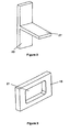
- the illustrated fastening clip 10 has a jumper shape with two superposed U's, nested one inside the other.
- the clip 10 is composed for this purpose of a base 11, from which extends, in an axial direction D1 of the clip 10, a pair of external lateral branches 12, 13 flexible offset between them in a lateral direction D2 of the staple 10. Between the outer branches 12, 13 is arranged a second pair of inner lateral branches 14, 15 offset from each other in the lateral direction D2.
- the internal branches 14, 15 are substantially parallel to each other and are also directed in the axial direction D1.
- the branches 12 to 15 are all arranged in the same plane including the axial and lateral directions D1, D2.
- the fastening clip 10 makes it possible to fasten two pieces to one another, these parts being formed for example by pieces of equipment of a motor vehicle.
- the pieces are designated by the references 19, 20.
- the first piece 19 ( figure 3 ), having a support function of the assembly, comprises an opening 21 in which is engaged axially the clip 10 for its clipping.
- the second piece 20 ( figure 2 ) is in turn hooked on the fastening clip 10, prior to the step of clipping the clip 10 on the first piece 19.
- the root base 11 has a general U shape, and has an intermediate portion 16 included in the lateral direction and in a transverse direction D3 perpendicular to the other two directions.
- the sides lateral portions of the intermediate portion 16 are connected to raised edges 17, 18 in the axial direction D1.
- each outer leg 12, 13 comprises a clipping hook 22, 23 shaped hollow, connected to a raised edge 17, 18 corresponding by a blade flexible 24, 25 inclined laterally inwardly of the clip 10 by approaching axially the top base 11.
- the clipping hook 22, 23 conjugate at its junction substantially at right angles to the associated flexible blade 24, 25 is a hard point clipping means on the edges of the opening 21 of the first piece 19.
- the lateral movement of the hooks 22, 23 is in particular the result of the elastic bending of the my hoses 24, 25.
- the junction zone between the raised edge 17, 18 of the base 11 and the corresponding flexible blade 24, 25 comprises two successive folds, offset in the axial direction D1 and inverted curvatures: a first fold connected to the raised edge 17, 18 and directed inwardly of the clip 10, and a second fold connected to the flexible blade 24, 25 and directed outwardly of the staple 10.
- the combined presence of the two plies successives has the effect of improving the distribution of mechanical stresses.
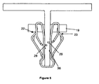
- each internal branch 14, 15 carries an element fastening 28, 29 directed laterally inwardly of the clip 10 towards the central housing 26 to retain the pin 27 in the central housing 26.
- Each inner branch 14, 15 comprises a first portion connected to the top base 11, respectively marked 30, 31 for the branches 14, 15.
- Each first portion 30, 31 is extended by a second folded portion 32, 33 outwardly of the staple 10 in the direction of the base base 11.
- Each folded portion 32, 33 comprises a folding zone 321, 331 elastically deformable and a blade 322, 332 free lateral movement carrying the fastening element 28, 29 corresponding.
- Each blade 322, 332 is broken down into a first section 322a, 332a connected to the folding zone 321, 331, directed substantially in the axial direction D1 of the clip 10, and into a second section 322b, 332b inclined laterally towards the inside of the staple 10 while approaching axially the summit base 11.
- the folding zone 321, 331 provides an arrangement of the blade 322, 332 partially laterally interposed between the first portion 30, 31 and the outer leg 12, 13 adjacent, laterally positioning, however, a blade portion at the hook of clipping 22, 23 carried the outer branch 12, 13 adjacent.
- the blade portion positioned laterally at the clipping hook that is to say in the same lateral plane as the bottom of the clipping hook 22, 23 carried by the outer leg 12, 13 adjacent, is positioned along the first blade section 322a, 332a, while the remainder of the blade 322, 332, in particular the second section 322b, 332b, is strictly laterally interposed between the first portion 30, 31 and the outer leg 12, 13 adjacent.
- the hooking elements 28, 29 are arranged at the free ends of the second sections 322b, 332b.
- the lateral retention in position of a blade portion 322, 332 at the bottom of the clipping hook 22, 23 is practiced through a passage formed laterally in the thickness of the bottom of the clipping hook 22, 23, avoiding any direct contact between said blade portion and the clipping hook 22, 23.
- each folded portion 32, 33 constitutes elastic means of lateral displacement of the element.
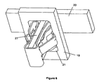
- latch 28, 29, so that the latter can vary selectively between a locking position ( figures 5 and 6 ) projecting inside the central housing 26 to axially lock the pin 27, or a release position ( figure 4 ) of the pin 27 released from the central housing 26, that is to say outside the housing 26.
- the blade portions held laterally at the clipping hooks 22, 23 form means for actuating the movement of the elements. 28, 29 to their locking positions, which actuating means are themselves automatically controlled by the action of clipping the clip 10 on the first piece 19.
- the elements of hooking 28, 29 are outside the housing 26 to release the post 27 make it removable axially from the housing 26.
- each fastening element 28, 29 is located at the same level in the transverse direction D3 of the clip 10.
- the first portion 30, 31 of each inner branch 14, 15 is provided with a passage hole 34, 35 of the fastening element 28, 29 carried by said internal branch 14, 15.
- the first portion 30, 31 of each inner leg 14, 15 is provided with retaining claws 36 of the attachment pin 27.
- the retaining claws 36 are directed towards the inside of the clip 10.
- the central housing 26 is delimited laterally by the first portions 30, 31 directly facing each other, the retaining claws 36 are continuously projecting inside the central housing 36, whatever the state of the clip 10, that is to say, it is clipped or not on the first piece 19, and that the pin 27 of the second piece 20 is or not engaged in the central housing 36.
- Such retaining claws 36 have the role of maintain in place the attachment pin 27 inside the central housing 26 directly at the time of its axial engagement, by engaging the claws 36 in the outer faces of the pin 27.
- This holding in place of the pin 27 by the claws 36 is automatic to ensure pre-assembly of the second piece 20 with the clip 10 (first assembly step: figure 4 before the movement of the fastening elements 28, 29 to their locking positions when clipping the clip 10 to the first piece 19 (second assembly step: figures 5 and 6 ).
- each hooking element 28, 29 has two main teeth directed laterally inwardly of the staple 10, offset relative to each other in the transverse direction D3, and connected in the transverse direction D3 of the staple 10 by an edge of curved compression laterally outwardly of the staple 10.
- each compression edge has an auxiliary tooth directed laterally inwardly of the staple 10. The end of the auxiliary tooth is shifted towards the outside of the staple 10 relative to the ends of the main teeth.
- the main teeth and the curved compression edge have two distinct functions.
- the teeth, pointed, constitute an aggressiveness zone rapidly initiating the penetration of the fastening elements 28, 29 into the attachment stud 27, while the curved compression edges have the role of gradually increasing the contact surface between the hooking elements 28, 29 and the attachment pin 27.
- the deep penetration of the main teeth increases the mechanical strength of the assembly.
- the auxiliary tooth is used in the case where the material of the fastening post 27 is relatively soft, to constitute an emergency element to overcome the low mechanical strength of the post 27.
- a first assembly step ( figure 4 ) it is necessary to engage axially the fastening pin 27 in the central housing 26, between the inner limbs 14, 15. With the pre-assembly retaining claws 36 provided on the first portions 30, 31 of the internal branches 14 , 15 to penetrate laterally into the post 27 during its axial engagement, the clip 10 is automatically secured to the second part 20, but the axial retention is not yet maximum.
- the dimensions of the opening 21 in the lateral direction D2 are slightly less than the distance between the clipping hooks 22, 23 when the external branches 12 , 13 are in their natural configuration, that is to say free of external constraints. In this way, when the hooks 22, 23 are engaged on the edges of the opening 21, the outer branches 12, 13 are slightly bent towards the inside of the clip 10, so as to be naturally recalled towards the outside permanently and to ensure the clipping of the clip 10 on the first part 19.
- the blade portion 322, 332 intended to be disposed laterally at the same level as the bottom of the clipping hook 22, 23 of the outer branch 12, 13 adjacent occupies such a position, in particular when said outer leg 12, 13 is in its natural configuration.
- the blade portions 322, 332 provided to be at the same level laterally as the hooks 22, 23 undergo a lateral approach (by flexion of the folding zones 321, 331 possibly combined at a bending of the blade 322, 332) of the same value as the approximation of the clipping hooks 22, 23.
- This approximation of the portions of the first blade section 322a, 332a 322, 332 causes a proportionally greater approximation of the fastening elements 28 , 29 towards each other.
- the edges of the hooks 22, 23 on the side of the junction with the flexible blades 24, 25 being inclined have the effect of creating a permanent axial compression between the parts 19, 20.
- these inclined edges of the hooks 22, 23 cause an automatic recoil of the parts 19, 20 against each other.
- the elements latching 28, 29 remain in the locking position.
- the attachment of the clip 10 to the second piece 20 is held firmly during the beginning of the axial outlet of the clip 10 relative to the opening 21 of the first piece 19.
- the clip 10 is made by cutting and folding a metal sheet of a relatively small thickness having undergone heat treatments adapted to confer elasticity properties.
- the second piece 20, and more particularly the attachment stud 27, are made of a material softer than the hooking elements 28, 29 of the clip 10 to allow the main and auxiliary teeth of the latter to sink In the material of the stud 27.
- the material selected may be an injectable thermoplastic material.
- the V configuration of the flexible blades 24, 25 and second sections 322b, 332b facilitate the introduction of the clip on the first piece 19.
- the first portions 30, 31 are inclined laterally towards the inside of the staple 10 while approaching the summit base 11 so as to form a V facilitating the establishment of the attachment stud 27 in the housing 26.
Landscapes
- Engineering & Computer Science (AREA)
- General Engineering & Computer Science (AREA)
- Mechanical Engineering (AREA)
- Clamps And Clips (AREA)
- Insertion Pins And Rivets (AREA)
Applications Claiming Priority (2)
| Application Number | Priority Date | Filing Date | Title |
|---|---|---|---|
| FR0802547A FR2930976B1 (fr) | 2008-05-07 | 2008-05-07 | Agrafe de fixation de deux pieces l'une sur l'autre |
| PCT/EP2009/003208 WO2009135643A1 (fr) | 2008-05-07 | 2009-05-05 | Agrafe de fixation de deux pièces l'une sur l'autre |
Publications (2)
| Publication Number | Publication Date |
|---|---|
| EP2286094A1 EP2286094A1 (fr) | 2011-02-23 |
| EP2286094B1 true EP2286094B1 (fr) | 2013-07-10 |
Family
ID=40254567
Family Applications (1)
| Application Number | Title | Priority Date | Filing Date |
|---|---|---|---|
| EP09741862.8A Active EP2286094B1 (fr) | 2008-05-07 | 2009-05-05 | Agrafe de fixation de deux pièces l'une sur l'autre |
Country Status (8)
| Country | Link |
|---|---|
| US (1) | US8370999B2 (zh) |
| EP (1) | EP2286094B1 (zh) |
| CN (1) | CN102016333B (zh) |
| BR (1) | BRPI0912406B1 (zh) |
| ES (1) | ES2424762T3 (zh) |
| FR (1) | FR2930976B1 (zh) |
| HK (1) | HK1151086A1 (zh) |
| WO (1) | WO2009135643A1 (zh) |
Families Citing this family (28)
| Publication number | Priority date | Publication date | Assignee | Title |
|---|---|---|---|---|
| JP4540726B2 (ja) * | 2008-07-04 | 2010-09-08 | 大和化成工業株式会社 | 二部材組付け構造 |
| ES2383871B1 (es) * | 2010-02-16 | 2013-05-07 | Illinois Tool Works Inc. | Clip rápido de fijación. |
| DE202011101112U1 (de) * | 2011-02-02 | 2012-08-28 | A. Raymond Et Cie | Befestigungsvorrichtung |
| US8561265B2 (en) * | 2011-04-12 | 2013-10-22 | Newfrey Llc | Interior trim fastener |
| CN104246242B (zh) * | 2012-04-02 | 2016-05-04 | 百乐仕株式会社 | 夹子以及夹子装置 |
| US9322420B2 (en) * | 2013-03-12 | 2016-04-26 | Trw Automotive U.S. Llc | Fastening method and apparatus |
| US9482399B2 (en) * | 2013-03-15 | 2016-11-01 | Vkr Holding A/S | Light tube kit for skylight |
| EP3012466B1 (de) * | 2013-07-15 | 2018-08-29 | BJB GmbH & Co. KG | Befestigungselement zur festlegung zweier bauteile aneinander |
| CN105229333B (zh) * | 2013-09-04 | 2017-03-08 | 华为终端有限公司 | 弹性装置及终端 |
| CN103940176B (zh) * | 2014-03-31 | 2016-01-13 | 合肥华凌股份有限公司 | 压缩机组件 |
| JP1518014S (zh) * | 2014-07-24 | 2015-02-23 | ||
| US9440596B2 (en) | 2014-11-20 | 2016-09-13 | Ford Global Technologies, Llc | Retention clip for interior vehicle components |
| WO2016192848A2 (de) | 2015-06-01 | 2016-12-08 | A. Raymond Et Cie. Scs | Vorrichtung zum zurückhalten eines bauteils |
| DE102015210063A1 (de) | 2015-06-01 | 2016-12-01 | A.RAYMOND et Cie. SCS | Vorrichtung zum Zurückhalten eines Bauteils |
| DE102015210092A1 (de) | 2015-06-01 | 2016-12-01 | A.RAYMOND et Cie. SCS | Vorrichtung zum Zurückhalten eines Bauteils |
| CN105465118B (zh) * | 2015-12-28 | 2018-05-22 | 安徽金诚天骏汽车零部件制造有限公司 | 板件连接装置 |
| EP3433501B1 (en) * | 2016-03-22 | 2020-04-29 | Illinois Tool Works, Inc. | Fastening clip |
| US10704577B2 (en) | 2017-10-18 | 2020-07-07 | Newfrey Llc | U-base fastener with folded barb |
| US10894516B2 (en) | 2017-10-18 | 2021-01-19 | Newfrey Llc | U-base fastener with folded barb and multiple spring arms |
| US10973321B2 (en) | 2018-09-04 | 2021-04-13 | Steelcase Inc. | Workspace system and components and method for the use thereof |
| DE102018127519A1 (de) * | 2018-11-05 | 2020-05-07 | Illinois Tool Works Inc. | Befestigungsclip zur Befestigung eines Anbauteils an einer Trägerkante |
| EP3660337B1 (en) * | 2018-11-30 | 2021-05-26 | A. Raymond et Cie | Clamping element, method for assembling a clamping element, method for clamping a clamping element and system of an element and a clamping element |
| US10900513B2 (en) | 2019-04-02 | 2021-01-26 | Newfrey Llc | Re-usable one-push pin and grommet fastener |
| EP3754207B1 (en) * | 2019-06-17 | 2022-08-03 | Illinois Tool Works Inc. | Fastening clip |
| USD934063S1 (en) | 2020-01-20 | 2021-10-26 | Illinois Tool Works Inc. | Fastening clip |
| US11400871B2 (en) | 2020-01-17 | 2022-08-02 | Illinois Tool Works Inc. | Metal retention clip |
| US11746812B2 (en) | 2021-05-12 | 2023-09-05 | Newfrey Llc | Dual component sealing fastener and coupling assembly including same |
| DE102023105023B3 (de) | 2023-03-01 | 2024-05-23 | Grammer Aktiengesellschaft | Halteklammer |
Family Cites Families (13)
| Publication number | Priority date | Publication date | Assignee | Title |
|---|---|---|---|---|
| US3977048A (en) * | 1975-09-15 | 1975-08-31 | Usm Corporation | Molding clips |
| JPH1054411A (ja) * | 1996-06-03 | 1998-02-24 | Daiwa Kasei Kogyo Kk | クリップ |
| DE29812707U1 (de) * | 1998-07-16 | 1998-12-10 | Trw Automotive Safety Sys Gmbh | Befestigungsvorrichtung für flächige Bauteile |
| US6353981B1 (en) * | 1999-02-25 | 2002-03-12 | Termax Corporation | Multi-engagement spring fastener |
| US6381811B2 (en) * | 2000-04-26 | 2002-05-07 | Termax Corporation | Sealing spring fastener with hermetically closed cavity |
| DE10059522A1 (de) * | 2000-11-30 | 2002-06-06 | Raymond A & Cie | Klammersystem zur Befestigung eines Anbauteils auf einem Trägerteil |
| JP2004519628A (ja) * | 2001-03-02 | 2004-07-02 | ニューフレイ リミテッド ライアビリティ カンパニー | 低挿入力のu字形ベースファスナ |
| US6718599B2 (en) * | 2001-06-25 | 2004-04-13 | Termax Corporation | Spring fastener with ergonomically balanced removal to insertion force ratio |
| US7784159B2 (en) * | 2002-06-07 | 2010-08-31 | Termax Corporation | Fastener with ergonomic removal to insertion force ratio |
| US6691380B2 (en) * | 2001-07-31 | 2004-02-17 | Eustathios Vassiliou Revocable Trust | Fasteners of increased holding power |
| WO2003100267A1 (en) * | 2002-05-28 | 2003-12-04 | Newfrey Llc | Resilient clip fastener and method of manufacturing the same |
| CN2733057Y (zh) * | 2003-12-30 | 2005-10-12 | 哈飞汽车股份有限公司 | 一种金属弹性卡扣 |
| US20080028577A1 (en) * | 2006-08-03 | 2008-02-07 | Mangesh Soman | Resilient two stage clip for automotive application |
-
2008
- 2008-05-07 FR FR0802547A patent/FR2930976B1/fr not_active Expired - Fee Related
-
2009
- 2009-05-05 US US12/936,274 patent/US8370999B2/en active Active
- 2009-05-05 EP EP09741862.8A patent/EP2286094B1/fr active Active
- 2009-05-05 CN CN2009801159737A patent/CN102016333B/zh active Active
- 2009-05-05 BR BRPI0912406-3A patent/BRPI0912406B1/pt active IP Right Grant
- 2009-05-05 ES ES09741862T patent/ES2424762T3/es active Active
- 2009-05-05 WO PCT/EP2009/003208 patent/WO2009135643A1/fr active Application Filing
-
2011
- 2011-05-24 HK HK11105134.3A patent/HK1151086A1/xx not_active IP Right Cessation
Also Published As
| Publication number | Publication date |
|---|---|
| US8370999B2 (en) | 2013-02-12 |
| CN102016333B (zh) | 2012-11-14 |
| ES2424762T3 (es) | 2013-10-08 |
| BRPI0912406B1 (pt) | 2019-07-30 |
| FR2930976A1 (fr) | 2009-11-13 |
| WO2009135643A1 (fr) | 2009-11-12 |
| FR2930976B1 (fr) | 2013-06-21 |
| WO2009135643A9 (fr) | 2010-01-07 |
| CN102016333A (zh) | 2011-04-13 |
| EP2286094A1 (fr) | 2011-02-23 |
| HK1151086A1 (en) | 2012-01-20 |
| BRPI0912406A2 (pt) | 2016-02-10 |
| US20110209309A1 (en) | 2011-09-01 |
Similar Documents
| Publication | Publication Date | Title |
|---|---|---|
| EP2286094B1 (fr) | Agrafe de fixation de deux pièces l'une sur l'autre | |
| EP2937575B1 (fr) | Dispositif de fixation par cramponnage | |
| EP2263014B1 (fr) | Dispositif de fixation d'un element d'assemblage d'un accessoire sur une plaque de support | |
| FR2898164A1 (fr) | Attache munie d'un pied d'encliquetage a enfoncer au travers du trou d'un panneau | |
| EP1850017B1 (fr) | Liason autobloquante entre une pièce plane et une tige à extrémité sphérique | |
| EP1251285A1 (fr) | Ensemble de deux pièces de carrosserie à réunir bord à bord et une pièce de carrosserie appartenant à un tel ensemble | |
| FR2967230A1 (fr) | Collier de serrage articule | |
| FR2981135A1 (fr) | Dispositif de fixation pour fixer un panneau a une paroi avec une resistance a l'arrachement elevee et ensemble comportant un tel dispositif | |
| EP3157837B1 (fr) | Collier de serrage a boucle transversale et outil de serrage | |
| FR2698922A1 (fr) | Organe de fixation à riveter. | |
| FR3088097A1 (fr) | Collier de serrage a doigt de retenue rabattable | |
| WO2016124728A1 (fr) | Frein à disque comportant au moins un ressort de rappel élastique d'un patin de freinage, ressort de rappel élastique, et kit de remplacement | |
| FR3020099A1 (fr) | Agrafe de fixation d'un panneau sur un support, procede de mise en oeuvre et equipement automobile | |
| EP2318797A2 (fr) | Dispositif de fixation pour un echangeur de chaleur a ailettes, notamment pour vehicules automobiles | |
| EP3561360B1 (fr) | Systeme de serrage a pattes rabattables pour le raccordement de tubes | |
| WO2020089389A1 (fr) | Attache et ensemble de fixation comprenant une telle attache | |
| FR2818352A1 (fr) | Collier de serrage | |
| EP2154024B1 (fr) | Système d'indexage d'un organe éclairant sur un véhicule automobile | |
| EP2730487B1 (fr) | Organe de maintien de deux éléments de carrosserie de véhicule automobile l'un contre l'autre | |
| FR2935031A1 (fr) | Dispositif pour fixer ensemble deux pieces, en une seule operation | |
| EP3734129A1 (fr) | Dispositif de serrage comprenant un collier et un joint d'etancheite | |
| EP2570566A2 (fr) | Dispositif couvre-joint pour revêtement de sol | |
| FR3026814A1 (fr) | Embout de connexion rapide pour un tube | |
| EP2525012A1 (fr) | Dispositif de protection permettant de coiffer au moins une partie du dessus d'une construction et installation correspondante | |
| EP2287473B1 (fr) | Système de fixation d'une patte mobile dans une coulisse fixe |
Legal Events
| Date | Code | Title | Description |
|---|---|---|---|
| PUAI | Public reference made under article 153(3) epc to a published international application that has entered the european phase |
Free format text: ORIGINAL CODE: 0009012 |
|
| 17P | Request for examination filed |
Effective date: 20101207 |
|
| AK | Designated contracting states |
Kind code of ref document: A1 Designated state(s): AT BE BG CH CY CZ DE DK EE ES FI FR GB GR HR HU IE IS IT LI LT LU LV MC MK MT NL NO PL PT RO SE SI SK TR |
|
| AX | Request for extension of the european patent |
Extension state: AL BA RS |
|
| DAX | Request for extension of the european patent (deleted) | ||
| GRAP | Despatch of communication of intention to grant a patent |
Free format text: ORIGINAL CODE: EPIDOSNIGR1 |
|
| GRAP | Despatch of communication of intention to grant a patent |
Free format text: ORIGINAL CODE: EPIDOSNIGR1 |
|
| GRAS | Grant fee paid |
Free format text: ORIGINAL CODE: EPIDOSNIGR3 |
|
| GRAA | (expected) grant |
Free format text: ORIGINAL CODE: 0009210 |
|
| AK | Designated contracting states |
Kind code of ref document: B1 Designated state(s): AT BE BG CH CY CZ DE DK EE ES FI FR GB GR HR HU IE IS IT LI LT LU LV MC MK MT NL NO PL PT RO SE SI SK TR |
|
| REG | Reference to a national code |
Ref country code: GB Ref legal event code: FG4D Free format text: NOT ENGLISH |
|
| REG | Reference to a national code |
Ref country code: AT Ref legal event code: REF Ref document number: 621142 Country of ref document: AT Kind code of ref document: T Effective date: 20130715 Ref country code: CH Ref legal event code: EP |
|
| REG | Reference to a national code |
Ref country code: IE Ref legal event code: FG4D Free format text: LANGUAGE OF EP DOCUMENT: FRENCH |
|
| REG | Reference to a national code |
Ref country code: DE Ref legal event code: R096 Ref document number: 602009017047 Country of ref document: DE Effective date: 20130912 |
|
| REG | Reference to a national code |
Ref country code: ES Ref legal event code: FG2A Ref document number: 2424762 Country of ref document: ES Kind code of ref document: T3 Effective date: 20131008 |
|
| PG25 | Lapsed in a contracting state [announced via postgrant information from national office to epo] |
Ref country code: SI Free format text: LAPSE BECAUSE OF FAILURE TO SUBMIT A TRANSLATION OF THE DESCRIPTION OR TO PAY THE FEE WITHIN THE PRESCRIBED TIME-LIMIT Effective date: 20130710 |
|
| REG | Reference to a national code |
Ref country code: AT Ref legal event code: MK05 Ref document number: 621142 Country of ref document: AT Kind code of ref document: T Effective date: 20130710 |
|
| REG | Reference to a national code |
Ref country code: NL Ref legal event code: VDEP Effective date: 20130710 |
|
| REG | Reference to a national code |
Ref country code: LT Ref legal event code: MG4D |
|
| PG25 | Lapsed in a contracting state [announced via postgrant information from national office to epo] |
Ref country code: HR Free format text: LAPSE BECAUSE OF FAILURE TO SUBMIT A TRANSLATION OF THE DESCRIPTION OR TO PAY THE FEE WITHIN THE PRESCRIBED TIME-LIMIT Effective date: 20130710 Ref country code: NO Free format text: LAPSE BECAUSE OF FAILURE TO SUBMIT A TRANSLATION OF THE DESCRIPTION OR TO PAY THE FEE WITHIN THE PRESCRIBED TIME-LIMIT Effective date: 20131010 Ref country code: PT Free format text: LAPSE BECAUSE OF FAILURE TO SUBMIT A TRANSLATION OF THE DESCRIPTION OR TO PAY THE FEE WITHIN THE PRESCRIBED TIME-LIMIT Effective date: 20131111 Ref country code: AT Free format text: LAPSE BECAUSE OF FAILURE TO SUBMIT A TRANSLATION OF THE DESCRIPTION OR TO PAY THE FEE WITHIN THE PRESCRIBED TIME-LIMIT Effective date: 20130710 Ref country code: SE Free format text: LAPSE BECAUSE OF FAILURE TO SUBMIT A TRANSLATION OF THE DESCRIPTION OR TO PAY THE FEE WITHIN THE PRESCRIBED TIME-LIMIT Effective date: 20130710 Ref country code: CY Free format text: LAPSE BECAUSE OF FAILURE TO SUBMIT A TRANSLATION OF THE DESCRIPTION OR TO PAY THE FEE WITHIN THE PRESCRIBED TIME-LIMIT Effective date: 20130918 Ref country code: LT Free format text: LAPSE BECAUSE OF FAILURE TO SUBMIT A TRANSLATION OF THE DESCRIPTION OR TO PAY THE FEE WITHIN THE PRESCRIBED TIME-LIMIT Effective date: 20130710 Ref country code: IS Free format text: LAPSE BECAUSE OF FAILURE TO SUBMIT A TRANSLATION OF THE DESCRIPTION OR TO PAY THE FEE WITHIN THE PRESCRIBED TIME-LIMIT Effective date: 20131110 |
|
| PG25 | Lapsed in a contracting state [announced via postgrant information from national office to epo] |
Ref country code: LV Free format text: LAPSE BECAUSE OF FAILURE TO SUBMIT A TRANSLATION OF THE DESCRIPTION OR TO PAY THE FEE WITHIN THE PRESCRIBED TIME-LIMIT Effective date: 20130710 Ref country code: NL Free format text: LAPSE BECAUSE OF FAILURE TO SUBMIT A TRANSLATION OF THE DESCRIPTION OR TO PAY THE FEE WITHIN THE PRESCRIBED TIME-LIMIT Effective date: 20130710 Ref country code: FI Free format text: LAPSE BECAUSE OF FAILURE TO SUBMIT A TRANSLATION OF THE DESCRIPTION OR TO PAY THE FEE WITHIN THE PRESCRIBED TIME-LIMIT Effective date: 20130710 Ref country code: GR Free format text: LAPSE BECAUSE OF FAILURE TO SUBMIT A TRANSLATION OF THE DESCRIPTION OR TO PAY THE FEE WITHIN THE PRESCRIBED TIME-LIMIT Effective date: 20131011 Ref country code: PL Free format text: LAPSE BECAUSE OF FAILURE TO SUBMIT A TRANSLATION OF THE DESCRIPTION OR TO PAY THE FEE WITHIN THE PRESCRIBED TIME-LIMIT Effective date: 20130710 |
|
| PG25 | Lapsed in a contracting state [announced via postgrant information from national office to epo] |
Ref country code: CY Free format text: LAPSE BECAUSE OF FAILURE TO SUBMIT A TRANSLATION OF THE DESCRIPTION OR TO PAY THE FEE WITHIN THE PRESCRIBED TIME-LIMIT Effective date: 20130710 |
|
| PG25 | Lapsed in a contracting state [announced via postgrant information from national office to epo] |
Ref country code: EE Free format text: LAPSE BECAUSE OF FAILURE TO SUBMIT A TRANSLATION OF THE DESCRIPTION OR TO PAY THE FEE WITHIN THE PRESCRIBED TIME-LIMIT Effective date: 20130710 Ref country code: CZ Free format text: LAPSE BECAUSE OF FAILURE TO SUBMIT A TRANSLATION OF THE DESCRIPTION OR TO PAY THE FEE WITHIN THE PRESCRIBED TIME-LIMIT Effective date: 20130710 Ref country code: RO Free format text: LAPSE BECAUSE OF FAILURE TO SUBMIT A TRANSLATION OF THE DESCRIPTION OR TO PAY THE FEE WITHIN THE PRESCRIBED TIME-LIMIT Effective date: 20130710 Ref country code: SK Free format text: LAPSE BECAUSE OF FAILURE TO SUBMIT A TRANSLATION OF THE DESCRIPTION OR TO PAY THE FEE WITHIN THE PRESCRIBED TIME-LIMIT Effective date: 20130710 Ref country code: DK Free format text: LAPSE BECAUSE OF FAILURE TO SUBMIT A TRANSLATION OF THE DESCRIPTION OR TO PAY THE FEE WITHIN THE PRESCRIBED TIME-LIMIT Effective date: 20130710 |
|
| PLBE | No opposition filed within time limit |
Free format text: ORIGINAL CODE: 0009261 |
|
| STAA | Information on the status of an ep patent application or granted ep patent |
Free format text: STATUS: NO OPPOSITION FILED WITHIN TIME LIMIT |
|
| 26N | No opposition filed |
Effective date: 20140411 |
|
| REG | Reference to a national code |
Ref country code: DE Ref legal event code: R082 Ref document number: 602009017047 Country of ref document: DE |
|
| REG | Reference to a national code |
Ref country code: DE Ref legal event code: R097 Ref document number: 602009017047 Country of ref document: DE Effective date: 20140411 |
|
| PG25 | Lapsed in a contracting state [announced via postgrant information from national office to epo] |
Ref country code: LU Free format text: LAPSE BECAUSE OF FAILURE TO SUBMIT A TRANSLATION OF THE DESCRIPTION OR TO PAY THE FEE WITHIN THE PRESCRIBED TIME-LIMIT Effective date: 20140505 |
|
| REG | Reference to a national code |
Ref country code: CH Ref legal event code: PL |
|
| PG25 | Lapsed in a contracting state [announced via postgrant information from national office to epo] |
Ref country code: MC Free format text: LAPSE BECAUSE OF FAILURE TO SUBMIT A TRANSLATION OF THE DESCRIPTION OR TO PAY THE FEE WITHIN THE PRESCRIBED TIME-LIMIT Effective date: 20130710 Ref country code: CH Free format text: LAPSE BECAUSE OF NON-PAYMENT OF DUE FEES Effective date: 20140531 Ref country code: LI Free format text: LAPSE BECAUSE OF NON-PAYMENT OF DUE FEES Effective date: 20140531 |
|
| REG | Reference to a national code |
Ref country code: IE Ref legal event code: MM4A |
|
| PG25 | Lapsed in a contracting state [announced via postgrant information from national office to epo] |
Ref country code: IE Free format text: LAPSE BECAUSE OF NON-PAYMENT OF DUE FEES Effective date: 20140505 |
|
| PG25 | Lapsed in a contracting state [announced via postgrant information from national office to epo] |
Ref country code: MT Free format text: LAPSE BECAUSE OF FAILURE TO SUBMIT A TRANSLATION OF THE DESCRIPTION OR TO PAY THE FEE WITHIN THE PRESCRIBED TIME-LIMIT Effective date: 20130710 |
|
| REG | Reference to a national code |
Ref country code: FR Ref legal event code: PLFP Year of fee payment: 8 |
|
| PG25 | Lapsed in a contracting state [announced via postgrant information from national office to epo] |
Ref country code: BG Free format text: LAPSE BECAUSE OF FAILURE TO SUBMIT A TRANSLATION OF THE DESCRIPTION OR TO PAY THE FEE WITHIN THE PRESCRIBED TIME-LIMIT Effective date: 20130710 |
|
| PG25 | Lapsed in a contracting state [announced via postgrant information from national office to epo] |
Ref country code: TR Free format text: LAPSE BECAUSE OF FAILURE TO SUBMIT A TRANSLATION OF THE DESCRIPTION OR TO PAY THE FEE WITHIN THE PRESCRIBED TIME-LIMIT Effective date: 20130710 Ref country code: BE Free format text: LAPSE BECAUSE OF FAILURE TO SUBMIT A TRANSLATION OF THE DESCRIPTION OR TO PAY THE FEE WITHIN THE PRESCRIBED TIME-LIMIT Effective date: 20140531 Ref country code: HU Free format text: LAPSE BECAUSE OF FAILURE TO SUBMIT A TRANSLATION OF THE DESCRIPTION OR TO PAY THE FEE WITHIN THE PRESCRIBED TIME-LIMIT; INVALID AB INITIO Effective date: 20090505 |
|
| REG | Reference to a national code |
Ref country code: FR Ref legal event code: PLFP Year of fee payment: 9 |
|
| REG | Reference to a national code |
Ref country code: FR Ref legal event code: PLFP Year of fee payment: 10 |
|
| PG25 | Lapsed in a contracting state [announced via postgrant information from national office to epo] |
Ref country code: MK Free format text: LAPSE BECAUSE OF FAILURE TO SUBMIT A TRANSLATION OF THE DESCRIPTION OR TO PAY THE FEE WITHIN THE PRESCRIBED TIME-LIMIT Effective date: 20130710 |
|
| P01 | Opt-out of the competence of the unified patent court (upc) registered |
Effective date: 20230524 |
|
| PGFP | Annual fee paid to national office [announced via postgrant information from national office to epo] |
Ref country code: IT Payment date: 20230526 Year of fee payment: 15 Ref country code: FR Payment date: 20230526 Year of fee payment: 15 Ref country code: DE Payment date: 20230519 Year of fee payment: 15 |
|
| PGFP | Annual fee paid to national office [announced via postgrant information from national office to epo] |
Ref country code: GB Payment date: 20230524 Year of fee payment: 15 Ref country code: ES Payment date: 20230724 Year of fee payment: 15 |