EP2285586B1 - Support d'impression composé d'au moins deux supports d'impression partiels assemblés de façon coplanaire, supports d'impression partiels et procédé de fabrication de ceux-ci - Google Patents
Support d'impression composé d'au moins deux supports d'impression partiels assemblés de façon coplanaire, supports d'impression partiels et procédé de fabrication de ceux-ci Download PDFInfo
- Publication number
- EP2285586B1 EP2285586B1 EP20090741650 EP09741650A EP2285586B1 EP 2285586 B1 EP2285586 B1 EP 2285586B1 EP 20090741650 EP20090741650 EP 20090741650 EP 09741650 A EP09741650 A EP 09741650A EP 2285586 B1 EP2285586 B1 EP 2285586B1
- Authority
- EP
- European Patent Office
- Prior art keywords
- partial
- layer
- printing
- print carrier
- carriers
- Prior art date
- Legal status (The legal status is an assumption and is not a legal conclusion. Google has not performed a legal analysis and makes no representation as to the accuracy of the status listed.)
- Not-in-force
Links
Images


Classifications
-
- B—PERFORMING OPERATIONS; TRANSPORTING
- B42—BOOKBINDING; ALBUMS; FILES; SPECIAL PRINTED MATTER
- B42D—BOOKS; BOOK COVERS; LOOSE LEAVES; PRINTED MATTER CHARACTERISED BY IDENTIFICATION OR SECURITY FEATURES; PRINTED MATTER OF SPECIAL FORMAT OR STYLE NOT OTHERWISE PROVIDED FOR; DEVICES FOR USE THEREWITH AND NOT OTHERWISE PROVIDED FOR; MOVABLE-STRIP WRITING OR READING APPARATUS
- B42D5/00—Sheets united without binding to form pads or blocks
- B42D5/02—Form sets
- B42D5/023—Continuous form sets
- B42D5/027—Sheets or cards attached to a carrier strip or web
-
- B—PERFORMING OPERATIONS; TRANSPORTING
- B42—BOOKBINDING; ALBUMS; FILES; SPECIAL PRINTED MATTER
- B42D—BOOKS; BOOK COVERS; LOOSE LEAVES; PRINTED MATTER CHARACTERISED BY IDENTIFICATION OR SECURITY FEATURES; PRINTED MATTER OF SPECIAL FORMAT OR STYLE NOT OTHERWISE PROVIDED FOR; DEVICES FOR USE THEREWITH AND NOT OTHERWISE PROVIDED FOR; MOVABLE-STRIP WRITING OR READING APPARATUS
- B42D15/00—Printed matter of special format or style not otherwise provided for
- B42D15/0073—Printed matter of special format or style not otherwise provided for characterised by shape or material of the sheets
-
- Y—GENERAL TAGGING OF NEW TECHNOLOGICAL DEVELOPMENTS; GENERAL TAGGING OF CROSS-SECTIONAL TECHNOLOGIES SPANNING OVER SEVERAL SECTIONS OF THE IPC; TECHNICAL SUBJECTS COVERED BY FORMER USPC CROSS-REFERENCE ART COLLECTIONS [XRACs] AND DIGESTS
- Y10—TECHNICAL SUBJECTS COVERED BY FORMER USPC
- Y10T—TECHNICAL SUBJECTS COVERED BY FORMER US CLASSIFICATION
- Y10T225/00—Severing by tearing or breaking
- Y10T225/10—Methods
-
- Y—GENERAL TAGGING OF NEW TECHNOLOGICAL DEVELOPMENTS; GENERAL TAGGING OF CROSS-SECTIONAL TECHNOLOGIES SPANNING OVER SEVERAL SECTIONS OF THE IPC; TECHNICAL SUBJECTS COVERED BY FORMER USPC CROSS-REFERENCE ART COLLECTIONS [XRACs] AND DIGESTS
- Y10—TECHNICAL SUBJECTS COVERED BY FORMER USPC
- Y10T—TECHNICAL SUBJECTS COVERED BY FORMER US CLASSIFICATION
- Y10T409/00—Gear cutting, milling, or planing
- Y10T409/30—Milling
- Y10T409/303752—Process
-
- Y—GENERAL TAGGING OF NEW TECHNOLOGICAL DEVELOPMENTS; GENERAL TAGGING OF CROSS-SECTIONAL TECHNOLOGIES SPANNING OVER SEVERAL SECTIONS OF THE IPC; TECHNICAL SUBJECTS COVERED BY FORMER USPC CROSS-REFERENCE ART COLLECTIONS [XRACs] AND DIGESTS
- Y10—TECHNICAL SUBJECTS COVERED BY FORMER USPC
- Y10T—TECHNICAL SUBJECTS COVERED BY FORMER US CLASSIFICATION
- Y10T428/00—Stock material or miscellaneous articles
- Y10T428/14—Layer or component removable to expose adhesive
-
- Y—GENERAL TAGGING OF NEW TECHNOLOGICAL DEVELOPMENTS; GENERAL TAGGING OF CROSS-SECTIONAL TECHNOLOGIES SPANNING OVER SEVERAL SECTIONS OF THE IPC; TECHNICAL SUBJECTS COVERED BY FORMER USPC CROSS-REFERENCE ART COLLECTIONS [XRACs] AND DIGESTS
- Y10—TECHNICAL SUBJECTS COVERED BY FORMER USPC
- Y10T—TECHNICAL SUBJECTS COVERED BY FORMER US CLASSIFICATION
- Y10T428/00—Stock material or miscellaneous articles
- Y10T428/24—Structurally defined web or sheet [e.g., overall dimension, etc.]
- Y10T428/24479—Structurally defined web or sheet [e.g., overall dimension, etc.] including variation in thickness
Definitions
- the present invention relates to a print carrier coplanarly assembled from at least two flat partial print carriers, one of the partial print carriers comprising a paper layer.
- the invention also relates to a partial print carrier with a paper layer and to a method for producing such a print carrier and partial print carrier.
- a print carrier or partial print carrier is to be understood as meaning in particular a sheet-like, web-shaped or sheet-like substrate which is printed on one or both sides and / or printable.
- the substrate can be constructed in one or more layers.
- print carriers based on paper sheets are needed, which are finished by local dispensers, usually in conjunction with die cuts, and contain, for example, integrated cards or labels.
- the dispensers are typically laminates that contain the pasting and adhesive layers needed for the integrated cards or labels. As an example can on WO 95/20493 to get expelled.
- WO 92/05036 has been proposed a print carrier in the form of a card laminate with a first card eg of paper and a second card, wherein the second card is mounted in a pressurized portion of the first card and with this has a coplanar surface, so that a skew in the stack is not can occur.
- this proposal could not be realized successfully because the depression in the paper material of the first card is likely to regress over time because of the high elasticity of paper, such as the aforementioned deformations.
- the two partial pressure carrier With its two edge strips, the two partial pressure carrier can be stably connected to each other in particular in mutual overlap. In the overlap region, a total thickness can be obtained that is not greater than the thickness of the partial print carrier otherwise.
- the two partial pressure carrier with their edge strips could also be connected to shock with at least one strip, in particular an adhesive strip, wherein the thickness of the strip is compensated by the smaller thickness of the partial pressure carrier in the region of its edge strips and by the at least one strip also in the Sum caused no increase in thickness compared to the thickness of the individual partial print carrier by the way.
- the partial layer of the paper layer is removed by tearing off.
- the invention makes use of the knowledge that paper material is fissile in itself and that a strip with a sub-layer of the paper material after a suitable tear virtually endless with an extremely constant thickness can be further demolished.
- the second print carrier is a multi-layered card laminate having at least two separable layers
- a stripe may be formed at least one layer of this laminate removed and thereby also a thickness reduction along a marginal strip are obtained.
- the marginal strip of the paper layer of the one partial print carrier is preferably bounded by the paper layer by an incision in the paper layer.
- the other partial print carrier in the direction of the edge strip is shorter than the partial print carrier comprising the paper layer.
- the two partial pressure carriers can be connected to one another by an adhesive strip, which is provided with a transponder.
- a transponder could also be contained in an adhesive strip which is glued along a weakened by removal of a sub-stripe strip of a print carrier.
- the invention also provides a partial print carrier with a paper layer for producing a novel print carrier, in which the paper layer along a marginal strip is weakened in its thickness by removing a partial layer.
- the partial layer of the paper layer is preferably removed by tearing off.
- the partial print carrier may be provided on the edge strip of the paper layer with an adhesive layer covered by a removable cover layer.
- the partial layer of the paper layer along the marginal strip is preferably removed by tearing off.
- the partial layer of the paper layer is torn off with an adhesive strip.
- Decisive for the resulting thickness of the sub-layer are the tear conditions.
- the adhesive strip is preferably pulled off via a roll together with the partial layer of the paper layer adhering to it.
- endless production in which the paper web and the adhesive strip are endless webs, both webs are passed over two successive running roles.
- tear conditions which correspond more to a lift
- a very uniform thickness for the sub-layer and thus also for the residual layer of the paper layer along the edge strip can be achieved.
- the thickness of the partial layer can be influenced by the choice of the diameter of the roll / s.
- edge strip of the paper layer In order for the edge strip of the paper layer to have a smooth edge with respect to the paper layer, it is delimited with an incision in the paper layer before the removal of the part layer.
- the depth of the incision should correspond approximately to the desired thickness of the sublayer.
- the edge strip on the latter may also be delimited by an incision in the laminate prior to detachment of the at least one layer from the laminate.
- the depth of the incision should in this case correspond at least to the desired thickness of the partial layer.
- an adhesive bond is used, more preferably, if that is required, an adhesive layer is dry transferred from a carrier to one of the two edge strips. Compared to a wet application of the adhesive layer, this has the advantage that the adhesive layer then immediately for bonding the two partial pressure carrier for Is available and does not have to be dried yet.
- a hot melt adhesive would also be suitable or a compound using an existing coating with pressing the two webs.
- the process for producing a print carrier or a partial print carrier according to the invention is preferably an endless process in which the two partial print carriers are present as webs, and e.g. from roll in the run, preferably simultaneously.
- the two partial printing carriers could possibly also be subjected to further processing steps, such as in the same pass. Printing or punching and ultimately to be singulated.
- a method according to the invention for essentially waste-free production of a print carrier in which the other partial print carrier in the direction of the marginal strip is shorter than the partial print carrier comprising the paper layer two outer and one medium partial print carriers are used, the two outer partial print carriers each comprising a paper layer and respectively along a marginal strip are weakened in their thickness by removing a partial layer and wherein the average partial pressure carrier along two, opposite edge strips has a smaller than its thickness otherwise.
- the outer partial pressure carriers are connected in each case along their edge strips with one of the edge strips of the middle partial printing carrier. Thereafter, the partial printing carriers connected in this way are subdivided into at least two of the printing substrates by a separating line guided alternately along the mutually opposite edge strips and intersecting the middle partial printing substrate.
- the size ratios of the various parts are not realistic.
- the thicknesses of the individual layers are greatly exaggerated for better visibility.
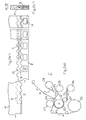
- Fig. 1 shows under g) one of two flat partial printing media A and B coplanar assembled with mutual overlap print carrier A / B.
- the partial print carrier A consists of a single layer or layer 1 of paper.
- the partial print carrier B is a laminate of approximately corresponding thickness of three layers 2, 3 and 4, wherein the layers 2 and 4 may also be a paper layer or a film layer and the layer 3 is a so-called Schallsim harsh which allows a detachment of the layer 2 of it while remaining on the layer 4.
- the partial printing substrates A and B are each weakened along an edge strip 5 or 6 by removing a strip-shaped partial layer 7 on the partial printing substrate A or a strip-shaped layer 8 on the partial printing substrate B in their thickness.
- the print carrier A and B can be provided in advance with cuts 9 and 10 respectively.
- Under a) and b) shows Fig. 1 the two partial printing carrier A and B in the original state, but already provided with such incisions 9 and 10.
- the strip-shaped sub-layer 7 of the paper layer 1 along the incision 9 of the paper layer 1 and thus the partial printing carrier A is shown separated, the separation by tearing under defibration of Paper material is done.
- the strip-shaped layer 8 along the incision 10 is shown detached from the partial pressure carrier B, wherein it forms part of the layer 2 and has detached from the Schallsim harsh 3.
- an adhesive 11 is applied in strip form, as is Fig. 1 e) shows.
- Fig. 1 f the two partial print carrier A and B with their edge strips 5 and 6 in mutual overlap finally glued together so that they come to lie substantially coplanar, like this Fig. 1 under g) shows.
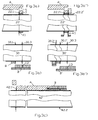
- Fig. 2 shows under a) a device for producing a print carrier A / B according to Fig. 1 in an endless process using partial printing media A and B, which are present as continuous webs and are unrolled from supply rolls 20 and 21.
- Fig. 2 shows Fig. 2 Supervision of the webs A and B in passing through the device of Fig. 2 a)
- c) is a section through the finished print carrier A / B shown.
- the web A of a first punching unit I with an underlying punching cylinder 22 and an overhead counter-cylinder 23 is supplied, wherein it runs in the punching unit on the counter-cylinder 23.
- the punching cylinder 22 is provided with at least one peripheral cutting edge for the attachment of the recess 9 of Fig. 1 during passage of the web A through the gap between the two cylinders 22 and 23 provided.
- a roller 24 abuts on the punching cylinder 22, via which a first adhesive strip K1 removed from a roll 25 with a carrying film layer and an adhesive layer is transferred onto the punching cylinder 22 with the adhesive layer facing outwards.
- a cover for the adhesive layer for example in the form of a silicone paper S1 is removed from the adhesive strip K1 and fed to a roll 26 on which it is wound up.
- the adhesive strip K1 comes in the gap between the two cylinders 22 and 23 with the web A in contact and is there under pressure firmly glued to this. Then it runs - with entrainment of a partial layer of the paper layer of the web A, as will be explained below - further around the punching cylinder 22 around to a deflection roller 27, via which it is away from the punching cylinder and a reeling at 28 is supplied.
- the adhesive strip K1 is dimensioned with respect to its width and relative to the web A and the incision 9 in this causing cutting edge 22.1 ( Fig. 3 a) ) is aligned so that it comes to lie between one of the side edges of the web A and the recess 9 and preferably also substantially fills the distance region between them. In particular, it rests on the punching cylinder 22 close to the cutting edge 22.1.
- the adhesive force of the adhesive layer of the adhesive strip K1 on the paper material of the web A is selected to be higher than the internal strength of the paper material, this tears or shreds in the running direction in said edge strip 5 in such a way that a partial layer of the paper layer corresponding to the partial layer. 7 from Fig. 1 adhering to the adhesive tape K1 remains on the punching cylinder 22, while the web A, moreover, rotates around the counter-cylinder 23.
- the partial layer 7 torn off by the adhesive strip K1 and adhering to it is rolled up on the roll 28 together with the adhesive strip K1.
- the specific tear conditions can be kept precisely constant in the procedure described in the flow, so that there is an approximately constant depth of travel with a correspondingly constant weakening of the web A along its edge strip 5.
- the web A with its weakened edge strip 5 is guided in the other via various pulleys to, inter alia, a second punching unit II around, which will be described below.
- the second punching unit II comprises an overhead punching cylinder 30 and an underlying counter-cylinder 31.
- This second punching unit II the web B is supplied from the supply roll 21 so that it runs on the counter-cylinder 31.
- the punching cylinder 30 is like the punching cylinder 22 with at least one peripheral cutting edge (30.1 in Fig. 3 b) ) for the attachment of the incision 10 of Fig. 1 during passage of the web B through the gap between the cylinders 30 and 31 provided.
- the strip-shaped layer 8 of Fig. 1 d) It is then cut free from the web B and can then be wound on a roll 32 around the punching cylinder 30.
- the web B with its weakened edge strip 6 is subsequently fed to a station III, in which an adhesive corresponding to the adhesive 11 of Fig. 1 e) strip is applied to the weakened edge strip 6.
- the adhesive 11 is applied dry by means of a pair of rollers 33, 34 and supplied thereto by a supply roll 35 on which it is arranged between two cover layers of silicone paper S2 and S3.
- One, S2, of these covering layers is drawn off from the roller 33 by a roller 36 before applying the adhesive layer 11 and rolled up on a roller 37.
- the other, S3, of these cover layers is removed only after the application of the adhesive 11 to the web B via a roller 38 thereof and wound on a roll 39.
- the adhesive 11 is then exposed on the top of the web B on the edge strip 6.
- its adhesive force must be significantly lower than that of the covering layer S3 compared with the covering layer S2.
- a further station IV with two pressure rollers 40 and 41 the web A and the web B are brought together and glued together in overlap of their two weakened edge strips 5 and 6 with the adhesive 11 under pressure, as well as from Fig. 2c) is apparent. It is important that the pressure is exerted by the rollers 40, 41 in the overlapping area, for which purpose a so-called dressing may be provided there.
- Fig. 2 a) It can be seen how the web A is guided around the pressure roller 40 and connected to the web B.
- Fig. 2 b) It can be seen that the two webs A and B are laterally offset from each other through the device, that in the station IV with the pressure rollers 40 and 41 both weakened edge strips fit each other exactly in the desired overlap and be pressed.
- a print carrier A / B according to the present invention already finished, albeit in the form of a continuous web, which could be wound on a roll 46 and provided for further continuous processing, for example, a printing company.
- a third punching unit V is provided with a punching cylinder 42 and a counter-cylinder 43, wherein on the punching cylinder 42 at least one aligned transversely to the direction of the web A / B cutting edge for cutting individual sheets from the web A / B is present.
- 44 denotes a device for taking over and destacking the separated sheets and 45 a sheet stack.
- the sheets may have common formats such as A4 or Letter.
- Fig. 3 illustrates under a), b) and c) the conditions on the three punching cylinders 22, 30 and 42 in the punching units I, II and V, wherein the individual figures each show longitudinal sections through the punching cylinder and wherein the cutting planes each as in Fig. 2 a) are indicated by dashed lines indicated.
- Fig. 3 a) shows the conditions on the punching cylinder 22 of the first punching unit I.
- the cutting plane is slightly obliquely chosen here, so that they the upper edge of the punching cylinder 22 shortly after the gap between him and the only in Fig. 2 a) illustrated mating cylinder 23 cuts.
- the circumferential on the punching cylinder 22 cutting edge for generating the recess 9 in the web A is denoted by 22.1 and formed on a thin blanking sheet, which is magnetically held on the punching cylinder 22.
- the punching cylinder 22 is to the way, like the other punching cylinder incidentally also formed as a magnetic cylinder.
- the adhesive tape K1 is, as already described, fed to the punching cylinder 22 in such a way that it bears tightly against the cutting edge 22.1. In the gap between the punching cylinder 22 and the counter-cylinder 23, the cutting edge 22.1 penetrates into the web A. Also, the adhesive strip K1 is glued to the web A under high pressure there. Practically at the same time begins in the gap and the demolition and separation of the sub-layer 7 of the web A by the adhesive strip K1 with the adhering to him sub-layer 7 on the punching cylinder 22 over a certain Rotation angle continues to run while the web A revolves around the counter-cylinder 23 and after the gap, as in Fig. 3 a) can be seen, removed from the adhesive strip K1 and the sub-layer 7.
- Fig. 3 b shows the conditions on the punching cylinder 30 of the second punching unit II.
- the cutting plane is again slightly obliquely chosen here, so that they the lower edge of the punching cylinder 30 shortly after the gap between him and the only in Fig. 2 a) dargestellen counter cylinder 31 cuts.
- the rotating on the punching cylinder 30 cutting edge for generating the incision 10 in the web B is designated 30.1 and in turn formed on a thin blanking sheet, which is magnetically held on the punching cylinder 30.
- the strip-shaped sublayer 8 of the web B cut free by the incision 10 is pulled off the web B by continuing to run on the punching cylinder 30 over a certain angle of rotation while the web B leaves the gap between the punching cylinder 30 and the counter-cylinder in a straight line ,
- the edge strips 5 and 6 of the two partial printing substrates A and B are each aligned straight and parallel to each other, both in terms of their outer edges and the cuts 9 and 10.
- the two cutting edges 22.1 'and 22.2' can also be advantageously used to cut out of the roll 25, for example with straight edges supplied adhesive tape K1 exactly in the wavy contour adhesive tape K1 ', of course, cutting waste accumulates here, however, can be removed together with the cover S1.
- the depth of the recess 9 plays practically no role in this context. This results in an edge-sharp separation of the sub-layer 7, even if the depth of the incision 9 is slightly less than the thickness of the sub-layer 7.
- the adhesive force of the device of Fig. 2 a) used adhesive strip K1 on the paper surface does not play a significant role in the thickness of the sub-layer 7, provided that this adhesive force is only large enough.
- the tear-off angle is determined on the one hand by the diameter of the punching cylinder 22 and on the other hand by that of the counter-cylinder 23.
- these diameters are 110-150 mm for the punching cylinder 22 and 60-140 mm for the counter-cylinder 23 and are therefore relatively large, which results in a relatively small pull-off angle and a thickness that is usually very low for practice for the torn-off partial layer 7.
- the modified punching unit I 'as shown in FIG Fig.2 d) is shown. In this, the web A and the adhesive strip K1 with the attached sub-layer 7 on a the punching and the counter-cylinder downstream roller pair 29 are separated from each other with a significantly smaller diameter.
- the thickness of the partial layer 7 can be set relatively precisely to the respective desired value, in particular in the range between 20-120 .mu.m, for example a thickness of 25 .mu.m for papers with 80 g / m.sup.2 and a thickness of 50 .mu.m for papers with 120 g / m2 is suitable.
- the thickness of the sub-layer can be 7 to 100 microns.
- Laminate used for the partial print carrier B or the web B is especially suitable for the production of integrated cards, in particular if the layer 2 is sufficiently thick, stiff and thus self-supporting.
- the device of Fig. 2 a) due to the punching units present in it anyway in the same pass along with the connection of the two webs A and B at least in the laminate of the web B in the layer 2 also just yet to produce such integrated cards.
- Fig. 3b ' is shown and designated 30.3 and cut with this the web B on the side of the layer 2 to the depth of Shulleimtik 3.
- the cards thus cut free from the layer 2 along their circumference are in Fig.2 b ) and Fig. 2 b ') with 12 and the corresponding cut in the layer 2 in Fig. 3 b) and Fig. 3 b ') is denoted by 13.
- the integrated cards 12 are held in the web B or in the finished print carrier A / B by the Schwarz 3 on the layer 4, but can be because of the separation properties of Schwarz 3 detached from the layer 4 and dissolved out of the print carrier A / B.
- a punching plate may be provided, for example, with a peripheral cutting edge 42.1, 42.1 individual print carrier sheets from the web A / B could be punched out to produce a stamped grid by this cutting edge 42.1 (in contrast to the cutting of the web under cross-cutting the same).
- the layer 4 of the web B could be cut with a peripheral cutting edge 42.2.
- the partial print carriers A and B were interconnected coplanarly with mutual overlap of their two weakened edge strips 5 and 6.
- Fig. 4 shows under a) - c) as in principle also would be possible without mutual overlapping of these edge strips on impact using a strip 15 or two strips 15 and 16, wherein the strip or strips bridge the joint area in each case.
- the total thickness of the residual thickness of the two edge strips and the thickness of the strip or stripes should again correspond approximately to the thickness of the two partial printing substrates A and B.
- the strips 15 and 16 may in particular be adhesive strips.
- partial pressure carriers A and B are in Fig. 4 not specified further in their structure.
- both partial print carriers could be a uniform paper layer.
- One or both partial print carrier could also be a multilayer laminate such as that for the partial print carrier B in FIG Fig. 1 shown and in the Fig. 2 and 3 used for making integrated cards.
- the layer 2 could be, in particular, a plastic film, for example of polyester, with a thickness in the range between 75 and 250 ⁇ m.
- the sound insulating layer could have a thickness in the range of 3 to 10 ⁇ m and the layer 4 could be a carrier layer with a thickness of 23 to 36 ⁇ m. It would result in this case, a total thickness for the partial print carrier B and thus preferably also for the paper material of the partial printing carrier A between 101 - 296 microns.
- the paper material would preferably be one which has a large volume at low weight, ie a low density.
- the two edge strips 5, 6 could, in particular in the case of a connection with mutual overlap, have a width of between 3 and 12 mm, but preferably between 4 and 8 mm.
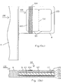
- FIGS. 5 to 8 Further selected examples of the layer structure of the two partial printing substrates A and B are explained, which on the one hand enables their inventive compound and on the other hand, the production of different integrated products, wherein in the FIGS. 5 to 7 the partial print carrier A in each case again consists only of a uniform paper layer and the partial print carrier B is in each case a multilayer laminate.
- the partial print carrier B from top to bottom has the following layer structure: a first Foliendeck für 50, a first pressure-sensitive adhesive layer 51, a paper layer 52, a second pressure-sensitive adhesive layer 53, a second Foliendeck für 54, a Schallsim für 55 and a support layer of paper or foil 56.
- Edge strip is a strip with the layers 50-54 removed from the Schwarzlleim für 55 and bonded there in overlap with a weakened edge strip of the partial print carrier A with an adhesive 57.
- the partial print carrier B from top to bottom, for example, consisting of paper layer 60, a pressure-sensitive adhesive layer 61, a silicone release layer 62 and a support layer 63 made of paper or foil.
- a strip with the layers 62 and 63 is removed from the pressure-sensitive adhesive layer 61 and bonded there in overlap with a weakened edge strip of the partial print carrier A using the pressure-sensitive adhesive of the pressure-sensitive adhesive layer 61.
- a partial self-adhesive label 65 is punched in the partial print carrier B, which due to the separation properties of the release layer 62 liberated and dissolved out under b) in Fig. 6 is shown.
- Fig. 7 shows that from a the laminate of the partial print carrier B of Fig. 6
- a non-sticky folding card 71 on the outside could be produced, which after folding and gluing together of their parts 72 and 73 over the thickness of the layer 70 more than twice the thickness.
- the layer 70 could advantageously be a relatively thick film layer here.
- Fig. 8 shows an embodiment in which also the partial print carrier A is a multilayer laminate and in addition to an upper paper layer 80 has a pressure-sensitive adhesive layer 81 and a carrier layer 82 made of tear-resistant film.
- This construction has the particular advantage that no extra adhesive strip is required for tearing off a partial layer of the paper layer 80 to its peripheral weakening, because such is already present through the layers 81 and 82. It is sufficient in this respect to provide the partial print carrier A with an incision, after which the integral layer of the paper layer 80 can be torn off immediately with the integrated adhesive strip.
- the partial print carrier B of Fig. 8 has the reverse layer order as the partial print carrier of Fig. 6 or 7 with the layers 83-86, wherein the layer 86 is a transparent film layer.
- a strip with the layers 83 and 84 is removed, wherein the layer 84 is indeed a release layer, which can easily be detached from the pressure-sensitive adhesive layer 85.
- the pressure-sensitive adhesive of this pressure-sensitive adhesive layer is used directly for the connection of the two partial printing substrates A and B, so that no extra adhesive is required for this purpose.
- a flip-card 90 in which a print 91 previously applied to the paper layer 80 of the partial print carrier A is protected beneath a transparent film layer.
- a first partial card 87 is punched free in the partial print carrier A by a first punching, but this is still held by individual webs in the carrier layer 82 in the partial printing carrier A.
- a second partial card 88 is punched free by a second punching, which is also held by individual webs in the layer 86 in the partial printing B carrier.
- the part designated by 89 comprising the layers 83 and 84 is removed from the partial print carrier B, whereby the region of the adhesive keeper layer 85 below this is uncovered.
- the partial print carrier B is folded onto the partial print carrier A around the connection zone as a joint, wherein the exposed pressure-sensitive adhesive layer 85 comes into contact with the surface of the partial card 87 provided with the mentioned imprint 91 and adheres to it can be.
- the finished flip-card 90 can be removed by breaking the mentioned webs from the print carrier A / B.
- Print media A / B according to the invention are ultimately required in the form of single sheets for their intended use, the formats A4 being 297 ⁇ 210 mm or letter 297 ⁇ 216 mm being the most common. If only a simple integrated card or label in the usual check card format of 85 x 54 mm is present in the partial print carrier B, this is less than half as wide as the partial print carrier B, even if it is arranged on a narrow side of the A4 or letter format , More than half of the material, which is usually much more expensive in comparison with the partial printing substrate A, for the partial printing substrate B is not utilized in this case.
- Fig. 2 b) shows this case. In contrast, training would be like them Fig.
- FIG. 9 a shows and in which the partial print carrier B extends only over half of the narrow side of the print carrier sheet or the partial print carrier A, in practice fully satisfy.
- Fig. 9b) shows the same print carrier sheet folded easily, the half-width partial print carrier B is supported and protected by the full width partial print carrier A and can be inserted easily in this form, for example, in an envelope.
- the method can be carried out with a device corresponding to that of Fig. 2a with the punching units I, II and III, with only additional units for the supply and connection of the third partial printing carrier web A2 with the partial printing carrier web B1 must be provided.
- the unrolling of the partial printing carrier web A2 can take place from the same shaft as for the partial printing carrier A1.
- the weakening of the edge strips, the various punching and gluing must be done in duplicate.
- Fig. 9 Supervision on the Trains A1, A2 and B1 in the passage through the units I - IV of a correspondingly formed device.
- the middle web B1 is, for example, a multilayer laminate according to the Fig. 5 , which is especially suitable for the production of integrated cards 12.
- the two outer partial print carriers A1, A2 can be paper webs.
- the resulting three-part print carrier web A1 / B1 / A2 shows Fig. 9 under d) and e) in sections C1 - C1 in Fig. 9c) or C2 - C2 in Fig. 9 f) ,
- the three-part print carrier web A1 / B1 / A2 are printed sheets 92 accordingly Fig. 9 a) oriented in pairs in opposite directions.
- the dividing line 93 between the opposing print carriers 92 runs alternately along the outer edges of the middle partial print carrier B1, as shown in FIG Fig. 9 e) is indicated and in between transversely through the middle partial print carrier B1 therethrough.
- the print carrier sheets 92 in the punching unit III are also cut to the desired format (punched lines 94), whereby a stamped grid is obtained.
- the print carrier sheets 92 in the punching unit III are also cut to the desired format (punched lines 94), whereby a stamped grid is obtained.
- Fig. 10 shows a) still another print carrier sheet 100 according to the invention in plan view, in which the partial print carrier B extends only over half of the narrow side of the print carrier sheet or the partial print carrier A.
- a folding card 101 is integrated here, the parts of which are designated 102 and 103.
- a magnetic strip 104 for storing information as an optional supplement.
- this print carrier sheet can be prepared by the method described above from a three-part print carrier web, with even the writing or reading of the magnetic stripe 104 could already be done on the current print carrier web.
- the layer structure of the print carrier 100 is made Fig. 10b) seen.
- the partial print carrier A as also shown, it may once again be a simple, edge-weakened paper layer.
- the partial print carrier B is a multilayer Laminate and has from top to bottom a layer 105 such as a plastic film, a pressure-sensitive adhesive view 106, a layer 107 such as paper, a further pressure-sensitive adhesive layer 108, a silicone release layer 109 and a support layer 110 such as paper or foil.
- a strip with the layers 109 and 110 is removed from the pressure-sensitive adhesive layer 108 and the partial print carrier B is glued there in overlap with a weakened edge strip of the partial print carrier A using the pressure-sensitive adhesive of the pressure-sensitive adhesive layer 108.
- the folding card 101 is punched with respect to the outer circumference of its two parts 102 and 103 and can be removed because of the separation properties of the release layer 109 from the partial print carrier B. be like this Fig. 10 under c) shows.
- a further punching line 112 is present as a folding aid, which in the layer 105 as a continuous full section, in the layer 107, however, as a perforation with webs and / or as a layer not completely through this Bleed is executed.
- the two parts 102 and 103 of the folding card 101 merely hang together via the layer 107 and, in this case, also only via individual webs and / or over a certain residual thickness. This is recognizable in Fig. 10d) , wherein here the cut line of the representation in the region of a punched web 113 between the two parts 102 and 103 is selected.
- Fig. 10 the folded folded and with respect to their parts 102 and 103 glued together folding card 101.
- the originating from the layer 105, the outer and thereby the outer layers of the folding card 101 forming layers have no connection with each other.
- Their vollum secured smooth and web-free cut edge essentially determines the outer contour of the folding card 101.
- the inner webs 113 between serving as the core layers of the folding card, originating from the layer 107 layers, however, are visually barely recognizable tactile virtually palpable.
- the folding card 101 as a whole in spite of the existing webs 113, gives the impression of a card on all sides. This is particularly pronounced when the cover layers are made of a relatively thick and stiff film and the core layers are thinner Consist of paper layer.
- To automatically read and write the magnetic stripe 104 on the finished card 101 it should have some rigidity anyway.
- Fig. 11 shows under a) one of two flat partial printing media A and B coplanar with mutual overlap assembled print carrier A / B similar to that of Fig. 1 g) ,
- the partial pressure carriers A and B are in Fig. 11 not specified further in their structure.
- both partial print carriers could be a uniform paper layer.
- One of the partial print carrier could also be a multilayer laminate such as that for the partial print carrier B in FIG Fig. 1 shown and in the Fig. 2 and 3 used for making integrated cards.
- the two partial print carriers A and B are in Fig. 11 a) each weakened edge and are coplanar with these edge strips 205 and 206 in mutual overlap by means of a special double-sided adhesive tape 210 connected to each other.
- the double-sided adhesive tape 210 has two outer adhesive layers 211 and 212 and a supporting layer 213 therebetween, which may be a simple film layer.
- Transponders which are also referred to as RFID tags, are passive memory chips without their own power supply but with antenna for contactless encoding with information or for contactless reading of information stored in them.
- Such transponders are usually mounted on a plurality of thin, laminated film layers (in Fig. 11 not shown) and can be produced according to the prior art for the present application already sufficiently thin and in strip form with eg only 10 mm wide at about 100 mm in length. A partial or even complete printing technology production is possible.
- the print carrier of Fig. 11 a is printable on both sides of the entire surface.
- the transponder 213 also does not cause any local thickening of the print carrier A / B, unlike when, for example, it was glued onto the print carrier like a label or laminated between two layers, as usual in the prior art. In the latter case, in order to avoid differences in thickness, the transponder would have to be designed to be the same size as the print carrier as a whole or else compensating layers would have to be laminated next to the transponder, both of which would not be very economical. The same applies to the lamination of a transponder between the same sized paper layers in the region of a weakened strip in one or both paper layers.
- the transponder In order for the transponder to come to lie properly in the bends possibly produced in the punching unit V, it must be suitably dimensioned with respect to its length and must also be controlled.
- the control can be achieved for example by means of a so-called insetting group (not shown), which is arranged between the supply roll 35 and the roller pair 33, 34 and by which the transponder web is stretched more or less slightly if necessary.
- To control the transponder track must be provided with tax stamps.
- transponders in print carrier sheets 92 of the type of Fig. 9 a If they are to be incorporated with an A4 or Letter format, they may only be half the width of the print carrier sheets in their length, so that one transponder can fit per print carrier sheet.
- Fig. 11b shows an embodiment according to the of Fig. 4a ), wherein the two edge strips 205 and 206 here do not overlap each other and are connected to each other with an adhesive strip 215.
- the adhesive strip 215 has a cover layer 216, in particular made of paper, a Hafkleber für 217 and between these two layers a transponder 218 corresponding to that of Fig. 11 a) on. Again, the transponder 218 is hidden in the print carrier A / B integrated and causes no local thickening of the print carrier.
- the print carrier of Fig. 11c) is a modification of the print carrier of Fig. 11b) , wherein here only along the weakened edge strip 205 of the partial print carrier A, an adhesive strip corresponding to the adhesive strip 215 with transponder 218 of Fig. 11b) is glued.
- This embodiment makes sense if it is all about providing a partial print carrier A with a transponder without thickness application and the partial print carrier B would not be of additional use.
- the adhesive tape 215 containing the transponder could also be regarded as a special type of partial print carrier B which simply lacks a thickened portion.
- the print carrier of Fig. 11d) is a modification of the print carrier of Fig. 11c)
- a weakening into which an adhesive strip corresponding to the adhesive strip 215 with transponder 218 of FIG Fig. 11b) is glued.
- the weakening along the strip 221 can in particular be generated again by tearing off a strip-like partial layer, for example after a prior provision of the print carrier D with possibly two parallel cuts, as described above, for example for the weakened edge strips 5, 6.
- the two interconnected partial pressure carrier should be as equal as possible thick. However, certain thickness differences can be tolerable. At least to +/- 5% thickness difference, the resulting flatness will be sufficient for most applications.
- Integrated cards, folding cards or labels typically have dimensions of 55 by 85 mm, so that the partial print carrier B preferably used for their production can have a width of 80 mm. If the partial print carrier B is arranged recordable in a format of an A4 sheet along one of its narrow sides, a height of at least more than 200 mm results for the partial print carrier A, so that the partial print carrier A, which indeed consists of a cost-effective paper material can be made in terms of area, the largest part of the print carrier A / B.
- the gradation along the marginal strip of the partial printing substrate B could be achieved not only by weaknesses with removal of individual layers but also by other measures, in particular directly in the laminate production.
- inventive print carrier A / B with integrated card can be produced in a single pass, wherein the method and the device used therefor may have to be slightly modified, depending on the layer structure of the partial print carrier used.
- the method and the device used therefor may have to be slightly modified, depending on the layer structure of the partial print carrier used.
- the print carrier of Fig. 8 no extra adhesive strip K1 and no glue 11 needed. It could also be that an adhesive is already present in the web A and that after the exposure of this adhesive only an uncoated ribbon would have to be applied. Possibly. the tearing off of the partial layer of the paper layer can also be carried out completely without the aid of an adhesive strip. It would also be possible to use only the first punching unit of Fig.
Landscapes
- Making Paper Articles (AREA)
- Credit Cards Or The Like (AREA)
- Printing Methods (AREA)
- Laminated Bodies (AREA)
Claims (14)
- Support d'impression (A/B; A'/B' ; A1/B1/A2) assemblé de façon coplanaire, composé d'au moins deux supports d'impression plans partiels (A, B ; A', B'), l'un des supports d'impression partiels (A ; A' ; A1, A2) comportant une couche de papier (1, 80), caractérisé en ce que l'épaisseur de la couche de papier (1, 80) d'un support d'impression partiel (A ; A') est réduite par enlèvement d'une couche partielle (7) le long d'une bande en bordure (5 ; 5'), et caractérisé en ce que la couche partielle (7) est retirée par arrachement, et caractérisé en ce que l'autre support d'impression partiel (B ; B') présente une bande en bordure (6 ; 6') dont l'épaisseur est réduite par rapport au reste du support d'impression partiel, et caractérisé en ce que les deux supports d'impression partiels (A, B ; A', B') sont reliés l'un à l'autre le long de leur deux bandes en bordure (5,6; 5', 6').
- Support d'impression selon la revendication 1, caractérisé en ce que l'une ou les deux bandes en bordure (5, 6; 5', 6') présentent une largeur comprise entre 3 et 12 mm, de préférence toutefois entre 4 et 8 mm.
- Support d'impression selon l'une des revendications 1 et 2, caractérisé en ce que les deux supports d'impression partiels (A, B ; A', B') sont reliés l'un à l'autre par chevauchement par les deux bandes en bordure le long de leur deux bandes en bordure (5, 6 ; 5', 6').
- Support d'impression selon l'une des revendications 1 et 2, caractérisé en ce que les deux supports d'impression partiels (A, B) sont reliés l'un à l'autre bord à bord par au moins une bande (15, 16) le long de leur deux bandes en bordure (5, 6).
- Support d'impression selon l'une des revendications 1 à 4, caractérisé en ce que les deux supports d'impression partiels (A, B ; A', B') sont à peu près de la même épaisseur.
- Support d'impression selon l'une des revendications 1 à 5, caractérisé en ce que son épaisseur, au niveau où les deux supports d'impression partiels (A, B ; A', B') sont reliés l'un à l'autre le long de leur deux bandes en bordure (5, 6, 5', 6'), n'est pas plus grande que l'épaisseur du plus épais des deux supports d'impression partiels.
- Support d'impression selon l'une des revendications 1 à 6, caractérisé en ce que la bande en bordure (5 ; 5') de la couche de papier (1) est limitée, par rapport au reste de la couche de papier (1), par une entaille (9 ; 9') dans la couche de papier (1).
- Support d'impression selon l'une des revendications 1 à 7, caractérisé en ce que l'autre support d'impression partiel (B ; B') est un stratifié avec au moins deux couches séparables l'une de l'autre (2, 4 ; 50 - 54, 56 ; 60, 63 ; 83, 86), desquelles au moins l'une des couches (2 ; 50 - 54 ; 63 ; 83) est éloignée le long de la bande en bordure (8).
- Support d'impression selon l'une des revendications 1 à 8, caractérisé en ce que les bordures de l'une ou des deux bandes en bordure (5, 6 ; 5', 6') sont formées de manière plane ou ondulée sur une face ou sur leurs deux faces.
- Support d'impression selon l'une des revendications 1 à 9, caractérisé en ce que l'autre support d'impression partiel (B ; B') est plus court dans le sens de la bande en bordure (8), et en particulier est deux fois moins long que le support d'impression partiel (A ; A') entourant la couche de papier (1 ; 80).
- Support d'impression selon l'une des revendications 1 à 3 ou 5 à 10, caractérisé en ce que l'autre support d'impression partiel (B) est un stratifié avec une couche utile relativement plus épaisse (60; 70) en papier ou en film, une couche adhésive autocollante (61), une couche de séparation en silicone (62) et avec une couche de support relativement plus mince (63) en papier ou en film et dont l'épaisseur de cet autre support d'impression partiel (B) est réduite le long de la bande en bordure par enlèvement de la couche de support (63) et de la couche de séparation en silicone (62) de la couche adhésive autocollante (61), et caractérisé en ce que les deux supports d'impression partiels (A, B) sont encollés par chevauchement le long de leur deux bandes en bordure au moyen de la colle adhésive de la couche adhésive autocollante (61).
- Support d'impression partiel (A ; A') en vue de la fabrication d'un support d'impression (A/B ; A'/B') selon l'une des revendications 1 à 11 avec une couche de papier (1 ; 80), dont l'épaisseur est réduite le long d'une bande en bordure (5 ; 5') par enlèvement d'une couche partielle (7), la couche partielle (7) étant retirée par arrachement.
- Support d'impression partiel (A ; A') selon la revendication 12, caractérisé en ce qu'une couche de colle recouverte par une couche de revêtement détachable est mise en place sur la bande (5) de la couche de papier (1).
- Procédé destiné à la fabrication de supports d'impression (A1/B1 ; A2/B1) selon la revendication 10 au moyen de deux supports d'impression partiels externes (A1, A2) et d'un support d'impression partiel central (B1), les deux supports d'impression partiels externes (A1, A2) comportant chacun une couche de papier, et dont l'épaisseur de chacun étant réduite le long d'une bande en bordure (5.1, 5.2) par enlèvement d'une couche partielle, et le support d'impression partiel central (B1) présentant deux bandes en bordure (6.1, 6.2) disposées à l'opposé l'une de l'autre, et dont l'épaisseur est réduite par rapport au reste du support d'impression partiel central, caractérisé en ce que les supports d'impression partiels externes (A1, A2) sont chacun reliés le long de leur bande en bordure (5.1, 5.2) par l'une des bandes en bordure (6.1, 6.2) du support d'impression partiel central (B1), et caractérisé en ce que les supports d'impression partiels (A1, B 1, A2) ainsi reliés les uns aux autres sont divisés dans au moins deux des supports d'impression par une ligne de séparation (93), qui traverse entre ceux-ci le support d'impression partiel central (B1), et est guidée en alternance le long de l'une des bandes en bordure (5.1, 6.1, 5.2, 6.2) disposées à l'opposé l'une de l'autre.
Applications Claiming Priority (4)
| Application Number | Priority Date | Filing Date | Title |
|---|---|---|---|
| CH7852008 | 2008-05-09 | ||
| CH8392008 | 2008-06-03 | ||
| US12/313,360 US8267430B2 (en) | 2008-05-09 | 2008-11-19 | Coplanar-joined printing carrier made from at least two partial printing carriers, the partial printing carriers, and the method for their fabrication |
| PCT/CH2009/000153 WO2009135332A2 (fr) | 2008-05-09 | 2009-05-11 | Support d'impression composé d'au moins deux supports d'impression partiels assemblés de façon coplanaire, supports d'impression partiels et procédé de fabrication de ceux-ci |
Publications (2)
| Publication Number | Publication Date |
|---|---|
| EP2285586A2 EP2285586A2 (fr) | 2011-02-23 |
| EP2285586B1 true EP2285586B1 (fr) | 2014-10-08 |
Family
ID=41050859
Family Applications (1)
| Application Number | Title | Priority Date | Filing Date |
|---|---|---|---|
| EP20090741650 Not-in-force EP2285586B1 (fr) | 2008-05-09 | 2009-05-11 | Support d'impression composé d'au moins deux supports d'impression partiels assemblés de façon coplanaire, supports d'impression partiels et procédé de fabrication de ceux-ci |
Country Status (8)
| Country | Link |
|---|---|
| US (2) | US8267430B2 (fr) |
| EP (1) | EP2285586B1 (fr) |
| CN (1) | CN102015321A (fr) |
| AU (1) | AU2009244023B2 (fr) |
| BR (1) | BRPI0912533A2 (fr) |
| CA (1) | CA2723748A1 (fr) |
| WO (1) | WO2009135332A2 (fr) |
| ZA (1) | ZA201008773B (fr) |
Families Citing this family (5)
| Publication number | Priority date | Publication date | Assignee | Title |
|---|---|---|---|---|
| CH702529A1 (de) | 2010-01-14 | 2011-07-15 | Fofitec Ag | Formular mit integrierter Faltkarte, Laminat zur Herstellung des Formulars und Verfahren zur Herstellung einer Faltkarte. |
| US8770488B2 (en) | 2010-08-12 | 2014-07-08 | Fofitec Ag | Method for the production of punched parts in web- or sheet-like print substrates and their further processing |
| US20130156987A1 (en) * | 2011-12-20 | 2013-06-20 | Fofitec Ag | Multilayer material, method for production thereof and printing stock produced therewith |
| US8846192B2 (en) | 2012-01-19 | 2014-09-30 | Ralph Giammarco | Enhanced film carrier |
| CH709365A1 (de) | 2014-03-11 | 2015-09-15 | Fofitec Ag | Aus wenigstens zwei flächigen Teildruckträgern koplanar zusammengefügter Druckträger. |
Family Cites Families (14)
| Publication number | Priority date | Publication date | Assignee | Title |
|---|---|---|---|---|
| NL8502769A (nl) * | 1984-12-07 | 1986-07-01 | Dojel Bernhard | Toegangskaart. |
| US5131686A (en) | 1990-09-20 | 1992-07-21 | Carlson Thomas S | Method for producing identification cards |
| US5403236A (en) * | 1993-03-04 | 1995-04-04 | Moore Business Forms, Inc. | ID card for printers held by repositional adhesive |
| US5522956A (en) * | 1994-01-24 | 1996-06-04 | Mccannel; Duncan | Card-carrying sheets, process of making and method of using the same |
| ES2112640T3 (es) | 1994-01-26 | 1998-04-01 | Fofitec Ag | Formulario con tarjeta separable, asi como material de soporte y material de recubrimiento, y procedimiento para su fabricacion. |
| US6159570A (en) * | 1994-10-24 | 2000-12-12 | Avery Dennison Corporation | Laminated card assembly |
| DE19741563A1 (de) | 1996-09-25 | 1998-03-26 | Fofitec Ag | Formular mit integrierter, herauslösbarer Karte, Herstellungsverfahren und Mehrschichtmaterial dafür |
| US6991259B2 (en) * | 1997-12-02 | 2006-01-31 | Strata-Tac, Inc. | Apparatus and method for improved business form with integrated card |
| US6352287B2 (en) * | 1997-12-02 | 2002-03-05 | Strata-Tac, Inc. | Apparatus and method for improved patch for business forms with integrated cards |
| US7374631B1 (en) * | 1998-09-22 | 2008-05-20 | Avery Dennison Corporation | Methods of forming printable media using a laminate sheet construction |
| WO2000041895A1 (fr) | 1999-01-13 | 2000-07-20 | Fofitec Ag | Support d'impression monte, dont les composants sont assembles entre eux sans recouvrement |
| US6749230B1 (en) * | 2000-05-18 | 2004-06-15 | Charles L. Casagrande | Business form with imaging compatible punch-out card and method |
| CH697456B1 (de) | 2004-04-13 | 2008-10-31 | Fofitec Ag | Bedruckbarer, blattförmiger Trà ger, Stapel solcher Trà ger und Verfahren zu ihrer Herstellung. |
| US7627972B2 (en) * | 2004-07-15 | 2009-12-08 | Avery Dennison Corporation | Printing stock with a label for making a security badge |
-
2008
- 2008-11-19 US US12/313,360 patent/US8267430B2/en not_active Expired - Fee Related
-
2009
- 2009-05-11 BR BRPI0912533A patent/BRPI0912533A2/pt not_active IP Right Cessation
- 2009-05-11 US US12/736,778 patent/US20110070403A1/en not_active Abandoned
- 2009-05-11 EP EP20090741650 patent/EP2285586B1/fr not_active Not-in-force
- 2009-05-11 CA CA 2723748 patent/CA2723748A1/fr not_active Abandoned
- 2009-05-11 CN CN2009801165013A patent/CN102015321A/zh active Pending
- 2009-05-11 WO PCT/CH2009/000153 patent/WO2009135332A2/fr active Application Filing
- 2009-05-11 AU AU2009244023A patent/AU2009244023B2/en not_active Ceased
-
2010
- 2010-12-07 ZA ZA2010/08773A patent/ZA201008773B/en unknown
Also Published As
| Publication number | Publication date |
|---|---|
| WO2009135332A3 (fr) | 2010-01-14 |
| WO2009135332A2 (fr) | 2009-11-12 |
| ZA201008773B (en) | 2012-01-25 |
| CN102015321A (zh) | 2011-04-13 |
| US8267430B2 (en) | 2012-09-18 |
| EP2285586A2 (fr) | 2011-02-23 |
| CA2723748A1 (fr) | 2009-11-12 |
| AU2009244023A1 (en) | 2009-11-12 |
| US20110070403A1 (en) | 2011-03-24 |
| BRPI0912533A2 (pt) | 2017-06-20 |
| US20090277351A1 (en) | 2009-11-12 |
| AU2009244023B2 (en) | 2015-11-19 |
Similar Documents
| Publication | Publication Date | Title |
|---|---|---|
| DE69933734T2 (de) | Etikettenbogen | |
| EP1268283B1 (fr) | Procede et dispositif de production des supports de donnees pourvus d'un transpondeur integre | |
| EP2285586B1 (fr) | Support d'impression composé d'au moins deux supports d'impression partiels assemblés de façon coplanaire, supports d'impression partiels et procédé de fabrication de ceux-ci | |
| EP1432631B1 (fr) | Bande adhesive detectable par machine | |
| DE60116139T2 (de) | Mehrschichtiges etikett sowie verfahren und vorrichtung zu dessen herstellung | |
| EP2603362A2 (fr) | Procédé de production de pièces estampées dans des supports d'impression en forme de bandes ou de feuilles, leur usinage ultérieur et les produits du procédé | |
| WO2011085505A1 (fr) | Formulaire comportant une carte pliante intégrée, et procédé de fabrication d'une carte pliante | |
| EP2821218B9 (fr) | Procédé de fabrication d'un étiquette adhésive composite imprimée | |
| WO1998026938A1 (fr) | Formulaire a carte integree | |
| WO2005100006A1 (fr) | Support imprimable sous forme de feuille, pile de tels supports et procede de production correspondant | |
| WO2008043193A2 (fr) | Formulaire comprenant une carte pliable pouvant être produite au moyen de ce formulaire et matériaux multicouches servant à produire un tel formulaire | |
| WO2011085506A1 (fr) | Formulaire comportant une carte pliante intégrée, et procédé de fabrication d'une carte pliante | |
| DE10134867B4 (de) | Verfahren und Vorrichtung zur Herstellung von Etiketten und aus diesem Verfahren erhältliches Etikett | |
| WO2008128362A1 (fr) | Formulaire avec carte pliante et distributeur pour la fabrication d'un tel formulaire | |
| EP3008668B1 (fr) | Procédé de fabrication pour des supports de données portatifs | |
| EP2794283A1 (fr) | Procédé de production d'un support d'impression | |
| DE102008020831B4 (de) | Booklet-Etikett und Verfahren zur Herstellung eines Booklet-Etiketts | |
| DE102016113965A1 (de) | Verfahren zur Herstellung von Etiketten und Schichtverbund | |
| CH709365A1 (de) | Aus wenigstens zwei flächigen Teildruckträgern koplanar zusammengefügter Druckträger. | |
| EP1648712B1 (fr) | Materiau de distribution servant a produire des objets comportant des cartes collees, procede de production et utilisation dudit materiau de distribution | |
| WO2003020532A1 (fr) | Matiere multicouche et formulaires produits au moyen de celle-ci | |
| DE3426635C2 (fr) | ||
| DE102020006911A1 (de) | Verfahren und Vorrichtung zum Zwischenspeichern von flexiblen Flachteilen | |
| DE20122264U1 (de) | Vorrichtung zum Herstellen von Datenträgern mit integriertem Transponder | |
| EP0737955A1 (fr) | Etiquette auto-collante |
Legal Events
| Date | Code | Title | Description |
|---|---|---|---|
| PUAI | Public reference made under article 153(3) epc to a published international application that has entered the european phase |
Free format text: ORIGINAL CODE: 0009012 |
|
| 17P | Request for examination filed |
Effective date: 20101125 |
|
| AK | Designated contracting states |
Kind code of ref document: A2 Designated state(s): AT BE BG CH CY CZ DE DK EE ES FI FR GB GR HR HU IE IS IT LI LT LU LV MC MK MT NL NO PL PT RO SE SI SK TR |
|
| AX | Request for extension of the european patent |
Extension state: AL BA RS |
|
| DAX | Request for extension of the european patent (deleted) | ||
| 17Q | First examination report despatched |
Effective date: 20130411 |
|
| GRAP | Despatch of communication of intention to grant a patent |
Free format text: ORIGINAL CODE: EPIDOSNIGR1 |
|
| INTG | Intention to grant announced |
Effective date: 20140318 |
|
| GRAP | Despatch of communication of intention to grant a patent |
Free format text: ORIGINAL CODE: EPIDOSNIGR1 |
|
| RIC1 | Information provided on ipc code assigned before grant |
Ipc: B42D 15/00 20060101ALI20140724BHEP Ipc: B42D 5/02 20060101AFI20140724BHEP |
|
| GRAS | Grant fee paid |
Free format text: ORIGINAL CODE: EPIDOSNIGR3 |
|
| GRAA | (expected) grant |
Free format text: ORIGINAL CODE: 0009210 |
|
| INTG | Intention to grant announced |
Effective date: 20140813 |
|
| RAP1 | Party data changed (applicant data changed or rights of an application transferred) |
Owner name: FOFITEC AG |
|
| AK | Designated contracting states |
Kind code of ref document: B1 Designated state(s): AT BE BG CH CY CZ DE DK EE ES FI FR GB GR HR HU IE IS IT LI LT LU LV MC MK MT NL NO PL PT RO SE SI SK TR |
|
| REG | Reference to a national code |
Ref country code: GB Ref legal event code: FG4D Free format text: NOT ENGLISH |
|
| REG | Reference to a national code |
Ref country code: CH Ref legal event code: EP Ref country code: AT Ref legal event code: REF Ref document number: 690377 Country of ref document: AT Kind code of ref document: T Effective date: 20141015 |
|
| REG | Reference to a national code |
Ref country code: IE Ref legal event code: FG4D Free format text: LANGUAGE OF EP DOCUMENT: GERMAN |
|
| REG | Reference to a national code |
Ref country code: DE Ref legal event code: R096 Ref document number: 502009010064 Country of ref document: DE Effective date: 20141120 |
|
| REG | Reference to a national code |
Ref country code: CH Ref legal event code: NV Representative=s name: RENTSCH PARTNER AG, CH |
|
| REG | Reference to a national code |
Ref country code: NL Ref legal event code: VDEP Effective date: 20141008 |
|
| REG | Reference to a national code |
Ref country code: LT Ref legal event code: MG4D |
|
| PG25 | Lapsed in a contracting state [announced via postgrant information from national office to epo] |
Ref country code: NL Free format text: LAPSE BECAUSE OF FAILURE TO SUBMIT A TRANSLATION OF THE DESCRIPTION OR TO PAY THE FEE WITHIN THE PRESCRIBED TIME-LIMIT Effective date: 20141008 |
|
| PG25 | Lapsed in a contracting state [announced via postgrant information from national office to epo] |
Ref country code: IS Free format text: LAPSE BECAUSE OF FAILURE TO SUBMIT A TRANSLATION OF THE DESCRIPTION OR TO PAY THE FEE WITHIN THE PRESCRIBED TIME-LIMIT Effective date: 20150208 Ref country code: NO Free format text: LAPSE BECAUSE OF FAILURE TO SUBMIT A TRANSLATION OF THE DESCRIPTION OR TO PAY THE FEE WITHIN THE PRESCRIBED TIME-LIMIT Effective date: 20150108 Ref country code: LT Free format text: LAPSE BECAUSE OF FAILURE TO SUBMIT A TRANSLATION OF THE DESCRIPTION OR TO PAY THE FEE WITHIN THE PRESCRIBED TIME-LIMIT Effective date: 20141008 Ref country code: PT Free format text: LAPSE BECAUSE OF FAILURE TO SUBMIT A TRANSLATION OF THE DESCRIPTION OR TO PAY THE FEE WITHIN THE PRESCRIBED TIME-LIMIT Effective date: 20150209 Ref country code: ES Free format text: LAPSE BECAUSE OF FAILURE TO SUBMIT A TRANSLATION OF THE DESCRIPTION OR TO PAY THE FEE WITHIN THE PRESCRIBED TIME-LIMIT Effective date: 20141008 Ref country code: FI Free format text: LAPSE BECAUSE OF FAILURE TO SUBMIT A TRANSLATION OF THE DESCRIPTION OR TO PAY THE FEE WITHIN THE PRESCRIBED TIME-LIMIT Effective date: 20141008 |
|
| PG25 | Lapsed in a contracting state [announced via postgrant information from national office to epo] |
Ref country code: GR Free format text: LAPSE BECAUSE OF FAILURE TO SUBMIT A TRANSLATION OF THE DESCRIPTION OR TO PAY THE FEE WITHIN THE PRESCRIBED TIME-LIMIT Effective date: 20150109 Ref country code: LV Free format text: LAPSE BECAUSE OF FAILURE TO SUBMIT A TRANSLATION OF THE DESCRIPTION OR TO PAY THE FEE WITHIN THE PRESCRIBED TIME-LIMIT Effective date: 20141008 Ref country code: SE Free format text: LAPSE BECAUSE OF FAILURE TO SUBMIT A TRANSLATION OF THE DESCRIPTION OR TO PAY THE FEE WITHIN THE PRESCRIBED TIME-LIMIT Effective date: 20141008 Ref country code: HR Free format text: LAPSE BECAUSE OF FAILURE TO SUBMIT A TRANSLATION OF THE DESCRIPTION OR TO PAY THE FEE WITHIN THE PRESCRIBED TIME-LIMIT Effective date: 20141008 Ref country code: CY Free format text: LAPSE BECAUSE OF FAILURE TO SUBMIT A TRANSLATION OF THE DESCRIPTION OR TO PAY THE FEE WITHIN THE PRESCRIBED TIME-LIMIT Effective date: 20141008 Ref country code: PL Free format text: LAPSE BECAUSE OF FAILURE TO SUBMIT A TRANSLATION OF THE DESCRIPTION OR TO PAY THE FEE WITHIN THE PRESCRIBED TIME-LIMIT Effective date: 20141008 |
|
| REG | Reference to a national code |
Ref country code: DE Ref legal event code: R097 Ref document number: 502009010064 Country of ref document: DE |
|
| PG25 | Lapsed in a contracting state [announced via postgrant information from national office to epo] |
Ref country code: RO Free format text: LAPSE BECAUSE OF FAILURE TO SUBMIT A TRANSLATION OF THE DESCRIPTION OR TO PAY THE FEE WITHIN THE PRESCRIBED TIME-LIMIT Effective date: 20141008 Ref country code: CZ Free format text: LAPSE BECAUSE OF FAILURE TO SUBMIT A TRANSLATION OF THE DESCRIPTION OR TO PAY THE FEE WITHIN THE PRESCRIBED TIME-LIMIT Effective date: 20141008 Ref country code: EE Free format text: LAPSE BECAUSE OF FAILURE TO SUBMIT A TRANSLATION OF THE DESCRIPTION OR TO PAY THE FEE WITHIN THE PRESCRIBED TIME-LIMIT Effective date: 20141008 Ref country code: DK Free format text: LAPSE BECAUSE OF FAILURE TO SUBMIT A TRANSLATION OF THE DESCRIPTION OR TO PAY THE FEE WITHIN THE PRESCRIBED TIME-LIMIT Effective date: 20141008 Ref country code: SK Free format text: LAPSE BECAUSE OF FAILURE TO SUBMIT A TRANSLATION OF THE DESCRIPTION OR TO PAY THE FEE WITHIN THE PRESCRIBED TIME-LIMIT Effective date: 20141008 |
|
| PLBE | No opposition filed within time limit |
Free format text: ORIGINAL CODE: 0009261 |
|
| STAA | Information on the status of an ep patent application or granted ep patent |
Free format text: STATUS: NO OPPOSITION FILED WITHIN TIME LIMIT |
|
| PG25 | Lapsed in a contracting state [announced via postgrant information from national office to epo] |
Ref country code: IT Free format text: LAPSE BECAUSE OF FAILURE TO SUBMIT A TRANSLATION OF THE DESCRIPTION OR TO PAY THE FEE WITHIN THE PRESCRIBED TIME-LIMIT Effective date: 20141008 |
|
| 26N | No opposition filed |
Effective date: 20150709 |
|
| GBPC | Gb: european patent ceased through non-payment of renewal fee |
Effective date: 20150511 |
|
| PG25 | Lapsed in a contracting state [announced via postgrant information from national office to epo] |
Ref country code: MC Free format text: LAPSE BECAUSE OF FAILURE TO SUBMIT A TRANSLATION OF THE DESCRIPTION OR TO PAY THE FEE WITHIN THE PRESCRIBED TIME-LIMIT Effective date: 20141008 Ref country code: LU Free format text: LAPSE BECAUSE OF FAILURE TO SUBMIT A TRANSLATION OF THE DESCRIPTION OR TO PAY THE FEE WITHIN THE PRESCRIBED TIME-LIMIT Effective date: 20150511 |
|
| PG25 | Lapsed in a contracting state [announced via postgrant information from national office to epo] |
Ref country code: SI Free format text: LAPSE BECAUSE OF FAILURE TO SUBMIT A TRANSLATION OF THE DESCRIPTION OR TO PAY THE FEE WITHIN THE PRESCRIBED TIME-LIMIT Effective date: 20141008 |
|
| PG25 | Lapsed in a contracting state [announced via postgrant information from national office to epo] |
Ref country code: GB Free format text: LAPSE BECAUSE OF NON-PAYMENT OF DUE FEES Effective date: 20150511 |
|
| REG | Reference to a national code |
Ref country code: FR Ref legal event code: PLFP Year of fee payment: 8 |
|
| REG | Reference to a national code |
Ref country code: GB Ref legal event code: S28 Free format text: APPLICATION FILED |
|
| REG | Reference to a national code |
Ref country code: AT Ref legal event code: MM01 Ref document number: 690377 Country of ref document: AT Kind code of ref document: T Effective date: 20150511 |
|
| PGFP | Annual fee paid to national office [announced via postgrant information from national office to epo] |
Ref country code: CH Payment date: 20160519 Year of fee payment: 8 Ref country code: IE Payment date: 20160610 Year of fee payment: 8 Ref country code: DE Payment date: 20160520 Year of fee payment: 8 |
|
| PG25 | Lapsed in a contracting state [announced via postgrant information from national office to epo] |
Ref country code: AT Free format text: LAPSE BECAUSE OF NON-PAYMENT OF DUE FEES Effective date: 20150511 |
|
| PGFP | Annual fee paid to national office [announced via postgrant information from national office to epo] |
Ref country code: FR Payment date: 20160520 Year of fee payment: 8 |
|
| REG | Reference to a national code |
Ref country code: GB Ref legal event code: S28 Free format text: APPLICATION WITHDRAWN Effective date: 20160906 |
|
| PG25 | Lapsed in a contracting state [announced via postgrant information from national office to epo] |
Ref country code: MT Free format text: LAPSE BECAUSE OF FAILURE TO SUBMIT A TRANSLATION OF THE DESCRIPTION OR TO PAY THE FEE WITHIN THE PRESCRIBED TIME-LIMIT Effective date: 20141008 |
|
| PG25 | Lapsed in a contracting state [announced via postgrant information from national office to epo] |
Ref country code: HU Free format text: LAPSE BECAUSE OF FAILURE TO SUBMIT A TRANSLATION OF THE DESCRIPTION OR TO PAY THE FEE WITHIN THE PRESCRIBED TIME-LIMIT; INVALID AB INITIO Effective date: 20090511 Ref country code: BG Free format text: LAPSE BECAUSE OF FAILURE TO SUBMIT A TRANSLATION OF THE DESCRIPTION OR TO PAY THE FEE WITHIN THE PRESCRIBED TIME-LIMIT Effective date: 20141008 |
|
| PG25 | Lapsed in a contracting state [announced via postgrant information from national office to epo] |
Ref country code: BE Free format text: LAPSE BECAUSE OF NON-PAYMENT OF DUE FEES Effective date: 20150531 |
|
| PG25 | Lapsed in a contracting state [announced via postgrant information from national office to epo] |
Ref country code: TR Free format text: LAPSE BECAUSE OF FAILURE TO SUBMIT A TRANSLATION OF THE DESCRIPTION OR TO PAY THE FEE WITHIN THE PRESCRIBED TIME-LIMIT Effective date: 20141008 |
|
| REG | Reference to a national code |
Ref country code: CH Ref legal event code: PCAR Free format text: NEW ADDRESS: BELLERIVESTRASSE 203 POSTFACH, 8034 ZUERICH (CH) |
|
| REG | Reference to a national code |
Ref country code: DE Ref legal event code: R119 Ref document number: 502009010064 Country of ref document: DE |
|
| REG | Reference to a national code |
Ref country code: CH Ref legal event code: PL |
|
| REG | Reference to a national code |
Ref country code: IE Ref legal event code: MM4A |
|
| PG25 | Lapsed in a contracting state [announced via postgrant information from national office to epo] |
Ref country code: LI Free format text: LAPSE BECAUSE OF NON-PAYMENT OF DUE FEES Effective date: 20170531 Ref country code: CH Free format text: LAPSE BECAUSE OF NON-PAYMENT OF DUE FEES Effective date: 20170531 |
|
| REG | Reference to a national code |
Ref country code: FR Ref legal event code: ST Effective date: 20180131 |
|
| PG25 | Lapsed in a contracting state [announced via postgrant information from national office to epo] |
Ref country code: IE Free format text: LAPSE BECAUSE OF NON-PAYMENT OF DUE FEES Effective date: 20170511 Ref country code: DE Free format text: LAPSE BECAUSE OF NON-PAYMENT OF DUE FEES Effective date: 20171201 |
|
| PG25 | Lapsed in a contracting state [announced via postgrant information from national office to epo] |
Ref country code: FR Free format text: LAPSE BECAUSE OF NON-PAYMENT OF DUE FEES Effective date: 20170531 |
|
| PG25 | Lapsed in a contracting state [announced via postgrant information from national office to epo] |
Ref country code: MK Free format text: LAPSE BECAUSE OF FAILURE TO SUBMIT A TRANSLATION OF THE DESCRIPTION OR TO PAY THE FEE WITHIN THE PRESCRIBED TIME-LIMIT Effective date: 20141008 |