EP2284857B1 - Elément de protection contre les surtensions - Google Patents
Elément de protection contre les surtensions Download PDFInfo
- Publication number
- EP2284857B1 EP2284857B1 EP10007818.7A EP10007818A EP2284857B1 EP 2284857 B1 EP2284857 B1 EP 2284857B1 EP 10007818 A EP10007818 A EP 10007818A EP 2284857 B1 EP2284857 B1 EP 2284857B1
- Authority
- EP
- European Patent Office
- Prior art keywords
- overvoltage protection
- overvoltage
- protection element
- limiting component
- housing
- Prior art date
- Legal status (The legal status is an assumption and is not a legal conclusion. Google has not performed a legal analysis and makes no representation as to the accuracy of the status listed.)
- Not-in-force
Links
Images
Classifications
-
- H—ELECTRICITY
- H01—ELECTRIC ELEMENTS
- H01H—ELECTRIC SWITCHES; RELAYS; SELECTORS; EMERGENCY PROTECTIVE DEVICES
- H01H37/00—Thermally-actuated switches
- H01H37/74—Switches in which only the opening movement or only the closing movement of a contact is effected by heating or cooling
- H01H37/76—Contact member actuated by melting of fusible material, actuated due to burning of combustible material or due to explosion of explosive material
- H01H37/761—Contact member actuated by melting of fusible material, actuated due to burning of combustible material or due to explosion of explosive material with a fusible element forming part of the switched circuit
- H01H2037/762—Contact member actuated by melting of fusible material, actuated due to burning of combustible material or due to explosion of explosive material with a fusible element forming part of the switched circuit using a spring for opening the circuit when the fusible element melts
Definitions
- the invention relates to an overvoltage protection element having a housing, with at least one overvoltage limiting component arranged in the housing, in particular a varistor, with two connection contacts for the electrical connection of the overvoltage protection element to the current or signal path to be protected, with an electrically conductive connection element and with one on the Wherein the first terminal contact is directly in electrical contact with the first pole of the overvoltage limiting component, wherein in the normal state of the overvoltage protection element, the connecting element with both the second terminal contact and with the second pole of the overvoltage limiting component via a thermally disconnecting compound in electrically conductive Contact, which then disconnects when the temperature of the overvoltage limiting device exceeds a predetermined limit temperature, and w obei is separated thermal connection, the connecting element is moved by the force of the spring system from the contact position by being moved out of the gap between the second terminal contact and the second pole of the overvoltage limiting component, so that the connecting element no longer electrically conductive contact with the second Terminal contact and the second pole of the overvoltage
- an overvoltage protection element which has a thermal separation device for monitoring the state of a varistor.
- the first connection element is connected via a flexible conductor to a rigid separation element whose end remote from the flexible conductor is connected via a solder joint to a connection lug provided on the varistor.
- the other connection element is connected via a flexible conductor fixed to the varistor or a terminal lug on the varistor.
- the separating element is acted upon by a spring system with a force which results in the separating element being linearly moved away from the connecting lug during the separation of the soldering connection, with the result that the varistor is electrically cut off in the event of thermal overloading.
- an overvoltage protection element in which the monitoring of the state of a varistor according to the principle of a temperature switch, so that when overheating of the varistor a provided between the varistor and a separator solder joint is separated, resulting in an electrical separation of the varistor.
- a plastic element is pushed by the restoring force of a spring from a first position to a second position in which the formed as a resilient metal tongue separating element is thermally and electrically separated from the varistor by the plastic element, so that a possibly between the metal tongue and the contact point of the varistor arcing arc is deleted. Since the plastic element has two color markings arranged next to one another, it also simultaneously functions as an optical status indicator, so that the state of the overvoltage protection element can be read directly on site.
- the DE 695 03 743 T2 discloses an overvoltage protection element with two varistors, which has two separating means, which can individually separate the varistors at their end of life.
- the separating means each have a resilient separating tongue, wherein the first end of the separating tongue firmly connected to the first terminal and the second end of the separating tongue is attached in the normal state of the overvoltage protection element via a solder joint to a connecting tongue on the varistor. If there is an inadmissible heating of the varistor, this leads to a melting of the solder joint.
- the separation tongue Since the separation tongue is deflected in the soldered state (normal state of the overvoltage protection element) from its rest position and thus biased, the free end of the separation tongue springs when softening the solder joint of the connecting tongue of the varistor, whereby the varistor is electrically disconnected.
- the cross section of the separation tongue may not be too large, so that it has a sufficient spring property.
- this also leads to a limitation of the maximum permissible pulse current.
- overvoltage protection element From the DE 699 04 274 T2 is an initially described overvoltage protection element known.
- this overvoltage protection element one end of a rigid spring-loaded metallic slide is soldered in the normal state of the overvoltage protection element both to the first connection element and to a connection lug connected to the varistor.
- An inadmissible heating of the varistor also leads here to a heating of the solder joint, so that the slider is pulled due to the force acting on it a spring from the junction between the first terminal and the terminal lug, resulting in an electrical separation of the varistor.
- the DE 10 2007 042 991 A1 discloses an overvoltage protection element comprising a housing, at least one varistor disposed in the housing, a pair of metallic stirrups as the electrically conductive connecting element, a spring, and a spring loaded slide as part of a mechanical severing device.
- the mutually parallel ends of the two current-dividing metallic bracket take in their midst a contact lug of the varistor, wherein the closed position is secured by a solder.
- the bracket enclose a space in which the spring-loaded slider is arranged.
- the known overvoltage protection elements are generally designed as a "protective plug", which together with a device lower part form an overvoltage protection device.
- a surge protection device which is intended to protect, for example, the phase-leading conductors L1, L2, L3 and the neutral conductor N and possibly also the earth conductor PE, corresponding terminals for the individual conductors are provided in the known surge protection devices on the device base.
- the connection contacts are designed as plug pins to the overvoltage protection element, which are arranged in the lower part of the device corresponding, connected to the terminals sockets, so that the overvoltage protection element is simply plugged onto the device base.
- overvoltage protection devices In such overvoltage protection devices, the installation and assembly by plugging the surge protection elements is very simple and time-saving feasible.
- overvoltage protection devices partially still have a changeover contact as a signal transmitter for Listeldung the state of at least one overvoltage protection element and an optical status display in the individual overvoltage protection elements.
- the status display indicates whether the overvoltage-limiting component arranged in the overvoltage protection element is still functional or not.
- varistors are used as overvoltage limiting component, although it is also possible to use gas-filled surge arresters, spark gaps or diodes depending on the intended use of the overvoltage protection element.
- thermal separation devices which are based on the melting of a solder joint, have to fulfill several tasks.
- a secure and good electrical connection between the first connection element and the overvoltage limiting component must be ensured.
- the separation point When a certain limit temperature is exceeded, the separation point must be a safe separation of the overvoltage limiting component and a permanent insulation resistance and tracking resistance guarantee.
- overvoltage protection element moreover have the smallest possible dimensions so that the overvoltage protection devices do not exceed the dimensions specified for DIN rail devices, this leads to the known overvoltage protection devices being able to be used only in the lower and middle power classes, ie for pulse currents ⁇ 65 kA.
- the present invention is therefore based on the object to provide an initially described overvoltage protection element, in which the aforementioned disadvantages are avoided. It should be ensured both a safe and good electrical connection in the normal state and a safe separation of a defective overvoltage limiting device. In addition, the highest possible insulation and tracking resistance should be achieved even with the smallest possible size of the overvoltage protection element, so that the overvoltage protection element can derive the highest possible pulse currents.
- the electrically conductive connecting element which is arranged in the normal state of the overvoltage protection element between the second terminal contact and the second pole of the overvoltage limiting component and electrically connected to both, is connected to an insulating separating element that with a disconnected thermal connection between the second terminal contact and is arranged on the second pole of the overvoltage limiting component, a possibly resulting when opening the separation point arc is reliably deleted by the retracting into the separation point insulating separator.
- an error of the overvoltage protection element is thus after the separation of the Soldering the conductive connecting element by the force of the spring system out of the gap between the second terminal contact and the second pole of the overvoltage limiting device moves out and moves the insulating separator into the space inside.
- the electrically conductive connecting element and the insulating separating element can be formed and connected to one another.
- the insulating separator may be formed, for example, by an insulating material circuit board having a region in which the surface of the circuit board is conductive on both sides, the conductive surfaces being electrically connected to each other by vias.
- the separator may also be made of a conductive material which is insulated except in the region of the connecting element, for example comprising an insulating coating or an insulating cover.
- the insulating separating element are formed by a rigid insulating material and the conductive connecting element of at least one metal piece, wherein the metal piece is preferably pressed in a formed in the insulating plate opening.
- the insulating separating element and the conductive connecting element are then firmly connected to each other, and form a common component, whereby on the one hand the assembly of the overvoltage protection element is simplified, on the other hand it is ensured that the conductive connecting element and the insulating separating element always move together.
- the second terminal contact is fixedly connected to a rigid metallic connection element, in which case in the normal state of the overvoltage protection element, the end of the rigid metallic terminal element facing away from the second terminal contact via a thermally disconnecting compound, d. H. via a solder connection to which one side of the conductive connection element is connected.
- the rigid metallic connecting element can be dimensioned so that it can easily transmit pulse currents with very high amplitudes.
- the second pole of the overvoltage limiting component or a connection lug connected to the pole is then soldered to one side of the connection element and the rigid metallic connection element is soldered to the other side of the connection element, so that the second connection contact via the metallic connection element and the Connecting element is electrically conductively connected to the second pole of the overvoltage limiting component or the terminal strap of the second pole.
- a release carriage is movably disposed within the housing, on which the spring system engages such that when separated thermal connection of the release carriage is moved by the force of the spring system from a first position to a second position.
- the release slide is connected to the insulating separating element or connecting element such that in the first position of the triggering slide the electrically conductive connecting element and in the second position of the triggering slide the insulating separating element between the second connecting contact and the second pole of the overvoltage limiting component or the connection tab is arranged.
- the release carriage thus serves to move the electrically conductive connection element out of the intermediate space between the second connection contact or the rigid metal connection element connected to the second connection contact and the second pole or the connection lug connected to the second pole. Since the conductive connecting element is firmly connected to the insulating separating element, the separating element is simultaneously moved into the intermediate space.
- At least one driving hook is arranged on the release carriage, which receives a portion of the insulating separating element.
- the insulating separating element is thus, preferably at its lower edge, received by the driving hook, so that the insulating separating element - and thus the conductive connecting element - is moved during the movement of the trigger slide from the first position to the second position upwards, so that the Pushed connecting element out of the intermediate space and the insulating separating element is pushed into the intermediate space.
- the connecting element is thus the only current-carrying element which is movably arranged.
- the metallic connection element like the connection contact, is rigid, so that both elements can be designed to be correspondingly robust and with a correspondingly large cross section, in order to be able to transmit large pulse currents safely.
- the overvoltage protection element according to the invention is advantageously designed as a "protective plug" so that it forms an overvoltage protection device together with a corresponding device lower part.
- the lower device part has a telecommunications contact for remote notification of the state of the overvoltage protection element.
- a trigger pin is provided in the overvoltage protection element, which protrudes through an opening in the bottom of the housing.
- the release pin is connected to the release carriage, so that moved simultaneously by the movement of the release carriage from the first position to the second position, the release pin, d. H. is raised.
- a quiver-like bore is formed in the release carriage, in which the release pin is arranged.
- the release pin serves at the same time for fastening or guiding two coil springs, which together with the release pin form the spring system.
- the two coil springs are arranged on the release pin, which has a flange in its central region, so that the one coil spring engages on the one hand on the housing and on the other hand on the flange of the release pin and the other coil spring on the one hand on the flange and on the other hand on the release carriage.
- error system is on the DE 42 41 311 C2 and referenced there and described spring system.
- an optical status indicator is provided which indicates whether the overvoltage-limiting component arranged in the overvoltage protection element is still functional or not.
- a colored display surface is preferably formed on the release carriage, wherein the display surface or a certain area of the display surface is arranged below a viewing window formed in the housing depending on the position of the release carriage.
- the viewing window can preferably be formed in the top of the housing, so that the status display is easy to read even when the overvoltage protection device is snapped onto a mounting rail.
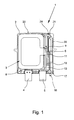
- the figures show an overvoltage protection element 1 with a housing 2, wherein a surge-limiting component 3 is arranged in the housing 2.
- the overvoltage limiting device is a varistor 3;
- a double varistor or a gas-filled surge arrester can be used as overvoltage limiting component 3.
- the as a protective plug formed overvoltage protection element 1 has two terminal contacts designed as a blade contacts 4, 5, which can be plugged into corresponding sockets of a device lower part, not shown here.
- the overvoltage protection element 1 also has a conductive connecting element 6 and a spring system 7.
- the two poles of the varistor 3 are each connected to a connecting lug 8, 9, wherein in the normal state of the overvoltage protection element 1, the varistor 3 is connected via the two connecting lugs 8, 9 with the two connection contacts 4, 5.
- the first terminal contact 4 is directly - preferably in one piece - connected to the terminal lug 8 of the first pole of the overvoltage limiting component 3.
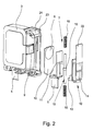
- the electrically conductive connecting element 6 is fixedly connected to an insulating separator 10, wherein in the illustrated embodiment, the connecting element 6 is formed by a metal piece and the insulating separator 10 by a rigid insulating plate having an opening in which the metal piece is pressed.
- the second connection contact 5 is fixedly connected to a rigid metallic connection element 11, which in the present case is designed as a connection angle.
- the rigid metallic connection element 11 is dimensioned so that it can derive pulse currents> 65 kA.
- the connecting element 6 is soldered, on the one hand, to the connecting lug 9 of the second pole of the varistor 3 and, on the other hand, to the end of the rigid connecting element 11 facing away from the second connecting contact 5, so that the second connecting contact 5 in the case of existing solder connections via the connecting element 11, Connecting element 6 and the terminal lug 9 is connected to the second pole of the varistor 3. Due to the robust design of these current-carrying mechanical parts, as already explained, even large pulse currents can be safely transmitted and thus dissipated.
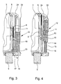
- the connecting element 6 is pushed by the force of the spring system 7 from the contact position up and at the same time the insulating separating element 10 is inserted into the intermediate space between the connecting lug 9 and the rigid connecting element 11.
- An emerging when opening the separation point arc is thus deleted directly by the retracting into the separation point insulating separator 10 so that a high insulation and tracking resistance and rapid quenching of an arc can be ensured without the distance between the terminal lug 9 of the second pole and the associated terminal contact 5 and the connection element 11 must be increased.
- the overvoltage protection element 1 can thus have relatively small dimensions, so that it is particularly suitable as a plug part in a latched onto a mounting rail device base. Since not the connection element 11 but only the connecting element 6 is moved, the connecting element 11 designed as a connection angle can be designed to be correspondingly robust and with a sufficiently large cross section.
- the overvoltage protection element 1 still has a release slide 12, which is preferably made of plastic.
- the release carriage 12 has in its lower region two driving hooks 13, which engage under the underside of the separating element 10.
- a one-sided closed bore 14 is formed in the release carriage 12, in which a release pin 15 is inserted, the lower end 16 protrudes from a arranged in the bottom 17 of the housing 2 opening, so that by the release pin 15 in a - not here shown - device lower part arranged switch a telecommunications contact can be operated.
- the release pin 15 has in its central region a circumferential flange 18, on whose front side in each case a plugged onto the trigger pin 15 coil spring 19 is present.
- the two coil springs 19 are tensioned, so that the lower coil spring 19 on the one hand on the housing 2 and on the other hand on the lower end face of the flange 18 and the upper coil spring 19 engages on the one hand on the upper end face of the flange 18 and on the other hand acting as a quiver on one side closed bore 14 in the release carriage 12.
- the separating element 10 entering the intermediate space interrupts the electrical connection between the second pole of the varistor 3 and the second connecting contact 5, so that the varistor 3 is electrically disconnected. At the same time an occurring switching arc is interrupted by the entering into the space separator 10 and thus deleted.
- an optical status display is provided, which can be recognized by a viewing window 21 formed in the upper side 20 of the housing 2.
- the optical state display is formed in the illustrated embodiment in that the release carriage 12 has a flexible colored display surface 22 which covers a formed on the inner housing 23 of the overvoltage protection element 1 differently colored area 24 in the second, upper position of the release carriage 12.
- the area 24 of the inner housing 23, which is located below the viewing window 21, for example, is dyed green, so that this green area 24 in the first, lower position of the trigger carriage 12 ( Fig. 3 ) is visible through the viewing window 21 in the top 20 of the housing 2.
- the flexible display surface 22 covers the colored area 24 of the inner housing, so that now through the viewing window 21 in the housing 2, the display surface 22 of the Shutter slide 12 is visible. If this display area 22 is dyed red, for example, it is quickly and easily recognizable through the viewing window 21 whether the varistor 3 is still functional (green status display) or defective and has therefore been disconnected electrically (red status display).
- the display surface 22 may also be formed bicolor-green area and red area, wherein, depending on the position of the release carriage 12, a portion of the display surface 22 through the viewing window 21 is visible.
Landscapes
- Chemical & Material Sciences (AREA)
- Engineering & Computer Science (AREA)
- Combustion & Propulsion (AREA)
- Fuses (AREA)
- Thermistors And Varistors (AREA)
- Emergency Protection Circuit Devices (AREA)
Claims (11)
- Élément de protection contre les surtensions muni d'un boîtier (2), comprenant au moins un composant de limitation des surtensions (3) disposé dans le boîtier (2), notamment une varistance, comprenant deux contacts de raccordement (4, 5) destinés au raccordement électrique de l'élément de protection contre les surtensions (1) au chemin de courant ou de signal à protéger, comprenant un élément de liaison (6) électriquement conducteur et comprenant un système à ressort (7) agissant sur l'élément de liaison (6),
le premier contact de raccordement (4) se trouvant en contact électriquement conducteur directement avec le premier pôle du composant de limitation des surtensions (3),
dans l'état normal de l'élément de protection contre les surtensions (1), l'élément de liaison (6) se trouvant en contact électriquement conducteur à la fois avec le deuxième contact de raccordement (5) et avec le deuxième pôle du composant de limitation des surtensions (3) par le biais d'une liaison à déconnexion thermique, laquelle s'ouvre lorsque la température du composant de limitation des surtensions (3) dépasse une température limite prédéfinie,
et, lorsque la liaison thermique est ouverte, l'élément de liaison (6) étant déplacé hors de la position de contact par la force du système à ressort (7), en ce qu'il est déplacé hors de l'espace intermédiaire entre le deuxième contact de raccordement (5) et le deuxième pôle du composant de limitation des surtensions (3) de sorte que l'élément de liaison (6) n'a plus aucun contact électriquement conducteur avec le deuxième contact de raccordement (5) et le deuxième pôle du composant de limitation des surtensions (3),
caractérisé en ce
que l'élément de liaison (6) électriquement conducteur est relié à demeure avec un élément de coupure isolant (10), l'élément de liaison (6) conducteur et l'élément de coupure (10) formant un composant commun, et
en ce que lorsque la liaison thermique est ouverte, l'élément de coupure isolant (10) est déplacé par la force du système à ressort (7) dans l'espace intermédiaire entre le deuxième contact de raccordement (5) et le deuxième pôle du composant de limitation des surtensions (3). - Élément de protection contre les surtensions selon la revendication 1, caractérisé en ce que l'élément de liaison (6) électriquement conducteur est formé par au moins une pièce métallique qui est ou sont disposée(s) dans l'élément de coupure isolant (10).
- Élément de protection contre les surtensions selon la revendication 1 ou 2, caractérisé en ce que l'élément de coupure isolant (10) est constitué d'une plaque en matériau isolant rigide.
- Élément de protection contre les surtensions selon l'une des revendications 1 à 3, caractérisé en ce qu'un élément de raccordement métallique (11) rigide est relié à demeure avec le deuxième contact de raccordement (5), une liaison à déconnexion thermique étant respectivement formée entre l'élément de liaison (6) et l'élément de raccordement métallique (11) ainsi qu'entre l'élément de liaison (6) et le deuxième pôle du composant de limitation des surtensions (3) dans l'état normal de l'élément de protection contre les surtensions (1).
- Élément de protection contre les surtensions selon l'une des revendications 1 à 4, caractérisé en ce qu'à l'intérieur du boîtier (2) est disposé mobile un coulisseau de déclenchement (12), lequel est relié avec l'élément de coupure isolant (10) et sur lequel vient en prise le système à ressort (7) de telle sorte que lorsque la liaison thermique est ouverte, le coulisseau de déclenchement (12) est déplacé par la force du système à ressort (7) d'une première position dans une deuxième position, l'élément de liaison (6) électriquement conducteur étant disposé entre le deuxième contact de raccordement (5) et le deuxième pôle du composant de limitation des surtensions (3) dans la première position du coulisseau de déclenchement (12), et l'élément de coupure isolant (10) y étant disposé dans la deuxième position du coulisseau de déclenchement (12).
- Élément de protection contre les surtensions selon la revendication 5, caractérisé en ce qu'au moins un crochet d'entraînement (13) est disposé sur le coulisseau de déclenchement (12), lequel accueille une portion de l'élément de coupure isolant (10).
- Élément de protection contre les surtensions selon la revendication 5 ou 6, caractérisé en ce que dans le coulisseau de déclenchement (12) est formé un alésage (14) dans lequel est disposée une goupille de déclenchement (15) destinée à actionner un contact de signalisation à distance qui fait saillie à travers une ouverture dans le côté inférieur (17) du boîtier (2).
- Élément de protection contre les surtensions selon la revendication 7, caractérisé en ce que la goupille de déclenchement (15) possède une bride (18) et le système à ressort (7) se compose de deux ressorts hélicoïdaux (19) qui sont disposés sur la goupille de déclenchement (15), l'un des ressorts hélicoïdaux (19) venant en prise d'un côté sur le boîtier (2) et de l'autre côté sur la bride (18) de la goupille de déclenchement (15) et l'autre ressort hélicoïdal (19) venant en prise d'un côté sur la bride (18) et de l'autre côté sur le coulisseau de déclenchement (12).
- Élément de protection contre les surtensions selon l'une des revendications 1 à 8, caractérisé en ce qu'il existe un indicateur d'état visuel et une fenêtre d'observation (21) est formée dans le boîtier (2).
- Élément de protection contre les surtensions selon la revendication 9, caractérisé en ce que le coulisseau de déclenchement (12) possède une surface d'indication (22) en couleur, la surface d'indication (22) ou une zone donnée de la surface d'indication (22), suivant la position du coulisseau de déclenchement (12), étant disposée au-dessous de la fenêtre d'observation (21) dans le boîtier (2).
- Élément de protection contre les surtensions selon la revendication 10, caractérisé en ce que le composant de limitation des surtensions (3) est au moins partiellement entouré par un boîtier interne (23), le boîtier interne (23) étant réalisé en couleur, par exemple en vert, au moins dans la zone (24) qui est disposée au-dessous de la fenêtre d'observation (21) dans le boîtier (2), et en ce que la surface d'indication (22) en couleur du coulisseau de déclenchement (12) est réalisée flexible et, dans la deuxième position du coulisseau de déclenchement (12), recouvre la zone colorée (24) du boîtier interne (23).
Priority Applications (1)
| Application Number | Priority Date | Filing Date | Title |
|---|---|---|---|
| SI201031082T SI2284857T1 (sl) | 2009-08-05 | 2010-07-28 | Element za varovanje pred električnim udarom |
Applications Claiming Priority (1)
| Application Number | Priority Date | Filing Date | Title |
|---|---|---|---|
| DE102009036125A DE102009036125A1 (de) | 2009-08-05 | 2009-08-05 | Überspannungsschutzelement |
Publications (3)
| Publication Number | Publication Date |
|---|---|
| EP2284857A2 EP2284857A2 (fr) | 2011-02-16 |
| EP2284857A3 EP2284857A3 (fr) | 2012-07-25 |
| EP2284857B1 true EP2284857B1 (fr) | 2015-11-25 |
Family
ID=43037704
Family Applications (1)
| Application Number | Title | Priority Date | Filing Date |
|---|---|---|---|
| EP10007818.7A Not-in-force EP2284857B1 (fr) | 2009-08-05 | 2010-07-28 | Elément de protection contre les surtensions |
Country Status (6)
| Country | Link |
|---|---|
| US (1) | US8477469B2 (fr) |
| EP (1) | EP2284857B1 (fr) |
| JP (1) | JP5669475B2 (fr) |
| CN (1) | CN102024542B (fr) |
| DE (1) | DE102009036125A1 (fr) |
| SI (1) | SI2284857T1 (fr) |
Cited By (2)
| Publication number | Priority date | Publication date | Assignee | Title |
|---|---|---|---|---|
| EP3460938A4 (fr) * | 2016-05-17 | 2019-06-12 | Guangxi NQT Electronic Technology Co., Ltd | Appareil de protection contre les surtensions à coupure rapide empêchant l'arc |
| EP4216237A3 (fr) * | 2022-01-24 | 2023-09-13 | Raycap IP Development LTD | Modules et ensembles de dispositif de protection contre les surtensions |
Families Citing this family (27)
| Publication number | Priority date | Publication date | Assignee | Title |
|---|---|---|---|---|
| DE102009053145A1 (de) | 2009-11-05 | 2011-05-12 | Phoenix Contact Gmbh & Co. Kg | Überspannungsschutzelement |
| FR2958789B1 (fr) * | 2010-04-09 | 2012-05-11 | Abb France | Dispositif de protection contre les surtensions transitoires a deconnecteur thermique ameliore |
| US8699197B2 (en) * | 2010-08-27 | 2014-04-15 | Cooper Technologies Company | Compact transient voltage surge suppression device |
| US8699198B2 (en) * | 2010-08-27 | 2014-04-15 | Cooper Technologies Company | Compact transient voltage surge suppression device |
| DE102011018556A1 (de) | 2011-02-18 | 2012-08-23 | Dehn + Söhne Gmbh + Co. Kg | Überspannungsschutzeinrichtung, umfassend mindestens einen Überspannungsableiter |
| US9165702B2 (en) * | 2011-03-07 | 2015-10-20 | James P. Hagerty | Thermally-protected varistor |
| CZ304868B6 (cs) * | 2011-04-01 | 2014-12-17 | Saltek S.R.O. | Svodič přepětí s výměnným modulem přepěťové ochrany |
| EP2541579B1 (fr) * | 2011-06-30 | 2015-11-04 | Epcos Ag | Dispositif électrique |
| DE102011052689B4 (de) * | 2011-08-12 | 2016-09-01 | Phoenix Contact Gmbh & Co. Kg | Gasgefüllter Überspannungsableiter mit indirekter Überwachung einer Kurzschlussfeder |
| DE102011052803A1 (de) * | 2011-08-18 | 2013-02-21 | Phoenix Contact Gmbh & Co. Kg | Basiselement zur Aufnahme eines Überspannungsschutzmoduls |
| DE102011053414B4 (de) | 2011-09-08 | 2016-11-17 | Phoenix Contact Gmbh & Co. Kg | Überspannungsschutzgerät mit einer thermischen Abtrennvorrichtung |
| ITMI20130915A1 (it) * | 2013-06-04 | 2014-12-05 | Con Trade S R L | Scaricatore di sovratensioni dotato di un dispositivo di segnalazione del suo stato di degrado. |
| DE102013021936B3 (de) * | 2013-10-08 | 2015-02-12 | Dehn + Söhne Gmbh + Co. Kg | Kompakte, vorkonfektionierbare Überspannungsschutzvorrichtung |
| DE102013022348B4 (de) * | 2013-10-22 | 2016-01-07 | Dehn + Söhne Gmbh + Co. Kg | Überspannungsschutzeinrichtung, aufweisend mindestens einen Überspannungsableiter und eine, mit dem Überspannungsableiter in Reihe geschaltete, thermisch auslösbare Schalteinrichtung |
| CN203761042U (zh) * | 2014-03-28 | 2014-08-06 | 佛山市浦斯电子有限公司 | 一种带灭弧的电涌抑制器 |
| DE102015213050A1 (de) | 2015-07-13 | 2017-01-19 | Phoenix Contact Gmbh & Co. Kg | Varistor mit einer Abtrennvorrichtung |
| DE102016015593B4 (de) * | 2016-06-10 | 2021-07-08 | Dehn Se + Co Kg | Überspannungsschutzanordnung mit mehreren, auf einer ersten Seite einer n-eckigen Trägerplatte angeordeten, scheibenförmigen Varistoren |
| DE102017112429B4 (de) * | 2017-06-06 | 2019-07-18 | Phoenix Contact Gmbh & Co. Kg | Überspannungsschutzelement |
| DE102017113852B4 (de) | 2017-06-22 | 2019-05-02 | Phoenix Contact Gmbh & Co. Kg | Überspannungsschutzelement |
| DE102017124219A1 (de) | 2017-10-18 | 2019-04-18 | Phoenix Contact Gmbh & Co. Kg | Überspannungsschutzgerät |
| DE102017124224B4 (de) * | 2017-10-18 | 2023-03-02 | Phoenix Contact Gmbh & Co. Kg | Überspannungsschutzgerät |
| DE102017131154B4 (de) * | 2017-12-22 | 2023-08-17 | Phoenix Contact Gmbh & Co. Kg | Überspannungsschutzanordnung |
| DE102018116354A1 (de) * | 2018-02-27 | 2019-08-29 | Dehn + Söhne Gmbh + Co. Kg | Überspannungsschutzanordnung, bestehend aus einer in einem isolierenden Gehäuse befindlichen Hörnerfunkenstrecke |
| DE102018125520A1 (de) * | 2018-10-15 | 2020-04-16 | Dehn Se + Co Kg | Überspannungsschutzgerät mit mehreren Überspannungsableitern und diesen jeweils zugeordneter, insbesondere thermischer, Abtrennvorrichtung |
| DE102019110006A1 (de) * | 2019-04-16 | 2020-10-22 | Phoenix Contact Gmbh & Co. Kg | Überspannungsschutzgerät |
| DE102019112680B4 (de) | 2019-05-15 | 2021-08-12 | Phoenix Contact Gmbh & Co. Kg | Überspannungsschutzgerät |
| DE102020121195A1 (de) | 2020-08-12 | 2022-02-17 | Phoenix Contact Gmbh & Co. Kg | Überspannungsschutzgerät |
Family Cites Families (12)
| Publication number | Priority date | Publication date | Assignee | Title |
|---|---|---|---|---|
| JPS5998590U (ja) * | 1982-12-22 | 1984-07-04 | 株式会社日辰電機製作所 | 避雷器回路用素子 |
| JPS59162795U (ja) * | 1983-04-15 | 1984-10-31 | 東京電力株式会社 | 避雷器の開放装置 |
| DE4241311C2 (de) | 1992-12-08 | 1995-06-08 | Phoenix Contact Gmbh & Co | Temperaturschalter mit einem Bausteingehäuse |
| FR2727806A1 (fr) | 1994-12-05 | 1996-06-07 | Soule Sa | Dispositif de protection a l'encontre de surtensions transitoires a base de varistances et deconnecteurs thermiques |
| JPH09134809A (ja) * | 1995-11-10 | 1997-05-20 | Matsushita Electric Ind Co Ltd | 安全保障機能付サージ吸収器 |
| US6430019B1 (en) * | 1998-06-08 | 2002-08-06 | Ferraz S.A. | Circuit protection device |
| FR2783365B1 (fr) | 1998-09-15 | 2000-12-01 | Soule Materiel Electr | Dispositif de protection d'installations electriques contre les perturbations de l'alimentation |
| DE202004006227U1 (de) | 2004-04-16 | 2004-09-16 | Phoenix Contact Gmbh & Co. Kg | Überspannungsschutzgerät |
| ES2386546T3 (es) * | 2004-04-19 | 2012-08-22 | Abb France | Dispositivo de protección contra las sobretensiones provisto de medios de desconexión y de visualización mejorados |
| RU2412496C2 (ru) * | 2005-08-05 | 2011-02-20 | Кива Спол. С Р.О. | Устройство защиты от перенапряжения с сигнализацией состояния |
| DE102007006617B3 (de) * | 2007-02-06 | 2008-09-04 | Phoenix Contact Gmbh & Co. Kg | Überspannungsschutzelement |
| DE102007042991B4 (de) * | 2007-06-11 | 2009-09-17 | Dehn + Söhne Gmbh + Co. Kg | Überspannungsschutzgerät mit im thermischen Überlastfall aktivierter mechanischer Abtrennvorrichtung |
-
2009
- 2009-08-05 DE DE102009036125A patent/DE102009036125A1/de not_active Ceased
-
2010
- 2010-07-28 SI SI201031082T patent/SI2284857T1/sl unknown
- 2010-07-28 EP EP10007818.7A patent/EP2284857B1/fr not_active Not-in-force
- 2010-08-03 US US12/849,541 patent/US8477469B2/en not_active Expired - Fee Related
- 2010-08-05 JP JP2010176245A patent/JP5669475B2/ja not_active Expired - Fee Related
- 2010-08-05 CN CN201010511619.0A patent/CN102024542B/zh not_active Expired - Fee Related
Cited By (2)
| Publication number | Priority date | Publication date | Assignee | Title |
|---|---|---|---|---|
| EP3460938A4 (fr) * | 2016-05-17 | 2019-06-12 | Guangxi NQT Electronic Technology Co., Ltd | Appareil de protection contre les surtensions à coupure rapide empêchant l'arc |
| EP4216237A3 (fr) * | 2022-01-24 | 2023-09-13 | Raycap IP Development LTD | Modules et ensembles de dispositif de protection contre les surtensions |
Also Published As
| Publication number | Publication date |
|---|---|
| SI2284857T1 (sl) | 2016-03-31 |
| DE102009036125A1 (de) | 2011-02-10 |
| JP2011034973A (ja) | 2011-02-17 |
| EP2284857A3 (fr) | 2012-07-25 |
| EP2284857A2 (fr) | 2011-02-16 |
| JP5669475B2 (ja) | 2015-02-12 |
| CN102024542B (zh) | 2015-09-30 |
| US20110032651A1 (en) | 2011-02-10 |
| CN102024542A (zh) | 2011-04-20 |
| US8477469B2 (en) | 2013-07-02 |
Similar Documents
| Publication | Publication Date | Title |
|---|---|---|
| EP2284857B1 (fr) | Elément de protection contre les surtensions | |
| DE102008048644B4 (de) | Überspannungsschutzgerät mit einem oder mehreren parallel geschalteten, in einer baulichen Einheit befindlichen überspannungsbegrenzenden Elementen | |
| DE102008031917B4 (de) | Überspannungschutzelement | |
| DE102011102941B4 (de) | Funkenstrecke mit mehreren in Reihe geschalteten, in einer Stapelanordnung befindlichen Einzelfunkenstrecken | |
| EP3120372B1 (fr) | Dispositif de protection contre les surtensions comprenant au moins un parafoudre et un moyen de commutation de court-circuit qui est précontraint par ressort, qui peut être déclenché thermiquement et qui est monté parallèlement au parafoudre | |
| DE102008029670B4 (de) | Überspannungsschutzelement | |
| DE102009053145A1 (de) | Überspannungsschutzelement | |
| DE202014103262U1 (de) | Überspannungsschutzelement | |
| DE102013022348B4 (de) | Überspannungsschutzeinrichtung, aufweisend mindestens einen Überspannungsableiter und eine, mit dem Überspannungsableiter in Reihe geschaltete, thermisch auslösbare Schalteinrichtung | |
| DE102012004678A1 (de) | Überspannungsschutzgerät | |
| DE102008061323B3 (de) | Überspannungsschutzelement | |
| EP2267850B1 (fr) | Elément de protection contre les surtensions | |
| DE102008013447A1 (de) | Überspannungsableiter mit einem Gehäuse und mindestens einem Ableitelement | |
| DE102017124224B4 (de) | Überspannungsschutzgerät | |
| EP2280457A2 (fr) | Elément de protection contre les surtensions | |
| DE102017112429B4 (de) | Überspannungsschutzelement | |
| DE202019103666U1 (de) | Überspannungsschutzelement und Überspannungsschutzgerät | |
| DE102017105029B4 (de) | Abschaltelement und Überspannungsschutzanordnung mit einem Abschaltelement | |
| DE102019117973B3 (de) | Überspannungsschutzelement | |
| DE102017124219A1 (de) | Überspannungsschutzgerät | |
| DE102017113852B4 (de) | Überspannungsschutzelement | |
| DE102017131154B4 (de) | Überspannungsschutzanordnung | |
| DE202012012287U1 (de) | Überspannungsschutzelement | |
| DE202020103719U1 (de) | Überspannungsschutzelement und Überspannungsschutzgerät | |
| DE202019103664U1 (de) | Überspannungsschutzelement |
Legal Events
| Date | Code | Title | Description |
|---|---|---|---|
| PUAI | Public reference made under article 153(3) epc to a published international application that has entered the european phase |
Free format text: ORIGINAL CODE: 0009012 |
|
| AK | Designated contracting states |
Kind code of ref document: A2 Designated state(s): AL AT BE BG CH CY CZ DE DK EE ES FI FR GB GR HR HU IE IS IT LI LT LU LV MC MK MT NL NO PL PT RO SE SI SK SM TR |
|
| AX | Request for extension of the european patent |
Extension state: BA ME RS |
|
| PUAL | Search report despatched |
Free format text: ORIGINAL CODE: 0009013 |
|
| AK | Designated contracting states |
Kind code of ref document: A3 Designated state(s): AL AT BE BG CH CY CZ DE DK EE ES FI FR GB GR HR HU IE IS IT LI LT LU LV MC MK MT NL NO PL PT RO SE SI SK SM TR |
|
| AX | Request for extension of the european patent |
Extension state: BA ME RS |
|
| RIC1 | Information provided on ipc code assigned before grant |
Ipc: H02H 9/04 20060101ALN20120619BHEP Ipc: H01C 7/12 20060101ALN20120619BHEP Ipc: H01H 37/76 20060101AFI20120619BHEP |
|
| 17P | Request for examination filed |
Effective date: 20130125 |
|
| GRAP | Despatch of communication of intention to grant a patent |
Free format text: ORIGINAL CODE: EPIDOSNIGR1 |
|
| RIC1 | Information provided on ipc code assigned before grant |
Ipc: H01H 37/76 20060101AFI20150518BHEP Ipc: H02H 9/04 20060101ALN20150518BHEP Ipc: H01C 7/12 20060101ALN20150518BHEP |
|
| INTG | Intention to grant announced |
Effective date: 20150608 |
|
| GRAS | Grant fee paid |
Free format text: ORIGINAL CODE: EPIDOSNIGR3 |
|
| GRAA | (expected) grant |
Free format text: ORIGINAL CODE: 0009210 |
|
| AK | Designated contracting states |
Kind code of ref document: B1 Designated state(s): AL AT BE BG CH CY CZ DE DK EE ES FI FR GB GR HR HU IE IS IT LI LT LU LV MC MK MT NL NO PL PT RO SE SI SK SM TR |
|
| REG | Reference to a national code |
Ref country code: GB Ref legal event code: FG4D Free format text: NOT ENGLISH |
|
| REG | Reference to a national code |
Ref country code: CH Ref legal event code: EP |
|
| REG | Reference to a national code |
Ref country code: AT Ref legal event code: REF Ref document number: 762969 Country of ref document: AT Kind code of ref document: T Effective date: 20151215 |
|
| REG | Reference to a national code |
Ref country code: IE Ref legal event code: FG4D Free format text: LANGUAGE OF EP DOCUMENT: GERMAN |
|
| REG | Reference to a national code |
Ref country code: DE Ref legal event code: R096 Ref document number: 502010010670 Country of ref document: DE |
|
| REG | Reference to a national code |
Ref country code: LT Ref legal event code: MG4D |
|
| REG | Reference to a national code |
Ref country code: NL Ref legal event code: MP Effective date: 20160225 |
|
| PG25 | Lapsed in a contracting state [announced via postgrant information from national office to epo] |
Ref country code: NO Free format text: LAPSE BECAUSE OF FAILURE TO SUBMIT A TRANSLATION OF THE DESCRIPTION OR TO PAY THE FEE WITHIN THE PRESCRIBED TIME-LIMIT Effective date: 20160225 Ref country code: LT Free format text: LAPSE BECAUSE OF FAILURE TO SUBMIT A TRANSLATION OF THE DESCRIPTION OR TO PAY THE FEE WITHIN THE PRESCRIBED TIME-LIMIT Effective date: 20151125 Ref country code: ES Free format text: LAPSE BECAUSE OF FAILURE TO SUBMIT A TRANSLATION OF THE DESCRIPTION OR TO PAY THE FEE WITHIN THE PRESCRIBED TIME-LIMIT Effective date: 20151125 Ref country code: NL Free format text: LAPSE BECAUSE OF FAILURE TO SUBMIT A TRANSLATION OF THE DESCRIPTION OR TO PAY THE FEE WITHIN THE PRESCRIBED TIME-LIMIT Effective date: 20151125 Ref country code: IS Free format text: LAPSE BECAUSE OF FAILURE TO SUBMIT A TRANSLATION OF THE DESCRIPTION OR TO PAY THE FEE WITHIN THE PRESCRIBED TIME-LIMIT Effective date: 20160325 Ref country code: HR Free format text: LAPSE BECAUSE OF FAILURE TO SUBMIT A TRANSLATION OF THE DESCRIPTION OR TO PAY THE FEE WITHIN THE PRESCRIBED TIME-LIMIT Effective date: 20151125 |
|
| PG25 | Lapsed in a contracting state [announced via postgrant information from national office to epo] |
Ref country code: GR Free format text: LAPSE BECAUSE OF FAILURE TO SUBMIT A TRANSLATION OF THE DESCRIPTION OR TO PAY THE FEE WITHIN THE PRESCRIBED TIME-LIMIT Effective date: 20160226 Ref country code: FI Free format text: LAPSE BECAUSE OF FAILURE TO SUBMIT A TRANSLATION OF THE DESCRIPTION OR TO PAY THE FEE WITHIN THE PRESCRIBED TIME-LIMIT Effective date: 20151125 Ref country code: SE Free format text: LAPSE BECAUSE OF FAILURE TO SUBMIT A TRANSLATION OF THE DESCRIPTION OR TO PAY THE FEE WITHIN THE PRESCRIBED TIME-LIMIT Effective date: 20151125 Ref country code: PT Free format text: LAPSE BECAUSE OF FAILURE TO SUBMIT A TRANSLATION OF THE DESCRIPTION OR TO PAY THE FEE WITHIN THE PRESCRIBED TIME-LIMIT Effective date: 20160325 Ref country code: LV Free format text: LAPSE BECAUSE OF FAILURE TO SUBMIT A TRANSLATION OF THE DESCRIPTION OR TO PAY THE FEE WITHIN THE PRESCRIBED TIME-LIMIT Effective date: 20151125 Ref country code: PL Free format text: LAPSE BECAUSE OF FAILURE TO SUBMIT A TRANSLATION OF THE DESCRIPTION OR TO PAY THE FEE WITHIN THE PRESCRIBED TIME-LIMIT Effective date: 20151125 |
|
| REG | Reference to a national code |
Ref country code: FR Ref legal event code: PLFP Year of fee payment: 7 |
|
| PG25 | Lapsed in a contracting state [announced via postgrant information from national office to epo] |
Ref country code: CZ Free format text: LAPSE BECAUSE OF FAILURE TO SUBMIT A TRANSLATION OF THE DESCRIPTION OR TO PAY THE FEE WITHIN THE PRESCRIBED TIME-LIMIT Effective date: 20151125 |
|
| REG | Reference to a national code |
Ref country code: DE Ref legal event code: R097 Ref document number: 502010010670 Country of ref document: DE |
|
| PG25 | Lapsed in a contracting state [announced via postgrant information from national office to epo] |
Ref country code: EE Free format text: LAPSE BECAUSE OF FAILURE TO SUBMIT A TRANSLATION OF THE DESCRIPTION OR TO PAY THE FEE WITHIN THE PRESCRIBED TIME-LIMIT Effective date: 20151125 Ref country code: RO Free format text: LAPSE BECAUSE OF FAILURE TO SUBMIT A TRANSLATION OF THE DESCRIPTION OR TO PAY THE FEE WITHIN THE PRESCRIBED TIME-LIMIT Effective date: 20151125 Ref country code: SK Free format text: LAPSE BECAUSE OF FAILURE TO SUBMIT A TRANSLATION OF THE DESCRIPTION OR TO PAY THE FEE WITHIN THE PRESCRIBED TIME-LIMIT Effective date: 20151125 Ref country code: DK Free format text: LAPSE BECAUSE OF FAILURE TO SUBMIT A TRANSLATION OF THE DESCRIPTION OR TO PAY THE FEE WITHIN THE PRESCRIBED TIME-LIMIT Effective date: 20151125 Ref country code: SM Free format text: LAPSE BECAUSE OF FAILURE TO SUBMIT A TRANSLATION OF THE DESCRIPTION OR TO PAY THE FEE WITHIN THE PRESCRIBED TIME-LIMIT Effective date: 20151125 |
|
| PLBE | No opposition filed within time limit |
Free format text: ORIGINAL CODE: 0009261 |
|
| STAA | Information on the status of an ep patent application or granted ep patent |
Free format text: STATUS: NO OPPOSITION FILED WITHIN TIME LIMIT |
|
| 26N | No opposition filed |
Effective date: 20160826 |
|
| PG25 | Lapsed in a contracting state [announced via postgrant information from national office to epo] |
Ref country code: BE Free format text: LAPSE BECAUSE OF NON-PAYMENT OF DUE FEES Effective date: 20160731 |
|
| REG | Reference to a national code |
Ref country code: CH Ref legal event code: PL |
|
| GBPC | Gb: european patent ceased through non-payment of renewal fee |
Effective date: 20160728 |
|
| PG25 | Lapsed in a contracting state [announced via postgrant information from national office to epo] |
Ref country code: MC Free format text: LAPSE BECAUSE OF FAILURE TO SUBMIT A TRANSLATION OF THE DESCRIPTION OR TO PAY THE FEE WITHIN THE PRESCRIBED TIME-LIMIT Effective date: 20151125 |
|
| PG25 | Lapsed in a contracting state [announced via postgrant information from national office to epo] |
Ref country code: CH Free format text: LAPSE BECAUSE OF NON-PAYMENT OF DUE FEES Effective date: 20160731 Ref country code: LI Free format text: LAPSE BECAUSE OF NON-PAYMENT OF DUE FEES Effective date: 20160731 |
|
| REG | Reference to a national code |
Ref country code: IE Ref legal event code: MM4A |
|
| PG25 | Lapsed in a contracting state [announced via postgrant information from national office to epo] |
Ref country code: GB Free format text: LAPSE BECAUSE OF NON-PAYMENT OF DUE FEES Effective date: 20160728 |
|
| REG | Reference to a national code |
Ref country code: FR Ref legal event code: PLFP Year of fee payment: 8 |
|
| PG25 | Lapsed in a contracting state [announced via postgrant information from national office to epo] |
Ref country code: IE Free format text: LAPSE BECAUSE OF NON-PAYMENT OF DUE FEES Effective date: 20160728 |
|
| PG25 | Lapsed in a contracting state [announced via postgrant information from national office to epo] |
Ref country code: LU Free format text: LAPSE BECAUSE OF NON-PAYMENT OF DUE FEES Effective date: 20160728 Ref country code: IT Free format text: LAPSE BECAUSE OF NON-PAYMENT OF DUE FEES Effective date: 20160728 |
|
| REG | Reference to a national code |
Ref country code: AT Ref legal event code: MM01 Ref document number: 762969 Country of ref document: AT Kind code of ref document: T Effective date: 20160728 |
|
| PG25 | Lapsed in a contracting state [announced via postgrant information from national office to epo] |
Ref country code: AT Free format text: LAPSE BECAUSE OF NON-PAYMENT OF DUE FEES Effective date: 20160728 |
|
| PGFP | Annual fee paid to national office [announced via postgrant information from national office to epo] |
Ref country code: FR Payment date: 20170727 Year of fee payment: 8 |
|
| PGFP | Annual fee paid to national office [announced via postgrant information from national office to epo] |
Ref country code: SI Payment date: 20170714 Year of fee payment: 8 |
|
| PG25 | Lapsed in a contracting state [announced via postgrant information from national office to epo] |
Ref country code: CY Free format text: LAPSE BECAUSE OF FAILURE TO SUBMIT A TRANSLATION OF THE DESCRIPTION OR TO PAY THE FEE WITHIN THE PRESCRIBED TIME-LIMIT Effective date: 20151125 Ref country code: HU Free format text: LAPSE BECAUSE OF FAILURE TO SUBMIT A TRANSLATION OF THE DESCRIPTION OR TO PAY THE FEE WITHIN THE PRESCRIBED TIME-LIMIT; INVALID AB INITIO Effective date: 20100728 |
|
| PG25 | Lapsed in a contracting state [announced via postgrant information from national office to epo] |
Ref country code: MT Free format text: LAPSE BECAUSE OF FAILURE TO SUBMIT A TRANSLATION OF THE DESCRIPTION OR TO PAY THE FEE WITHIN THE PRESCRIBED TIME-LIMIT Effective date: 20151125 Ref country code: TR Free format text: LAPSE BECAUSE OF FAILURE TO SUBMIT A TRANSLATION OF THE DESCRIPTION OR TO PAY THE FEE WITHIN THE PRESCRIBED TIME-LIMIT Effective date: 20151125 Ref country code: MK Free format text: LAPSE BECAUSE OF FAILURE TO SUBMIT A TRANSLATION OF THE DESCRIPTION OR TO PAY THE FEE WITHIN THE PRESCRIBED TIME-LIMIT Effective date: 20151125 |
|
| PG25 | Lapsed in a contracting state [announced via postgrant information from national office to epo] |
Ref country code: BG Free format text: LAPSE BECAUSE OF FAILURE TO SUBMIT A TRANSLATION OF THE DESCRIPTION OR TO PAY THE FEE WITHIN THE PRESCRIBED TIME-LIMIT Effective date: 20151125 |
|
| PG25 | Lapsed in a contracting state [announced via postgrant information from national office to epo] |
Ref country code: AL Free format text: LAPSE BECAUSE OF FAILURE TO SUBMIT A TRANSLATION OF THE DESCRIPTION OR TO PAY THE FEE WITHIN THE PRESCRIBED TIME-LIMIT Effective date: 20151125 |
|
| PG25 | Lapsed in a contracting state [announced via postgrant information from national office to epo] |
Ref country code: FR Free format text: LAPSE BECAUSE OF NON-PAYMENT OF DUE FEES Effective date: 20180731 |
|
| REG | Reference to a national code |
Ref country code: SI Ref legal event code: KO00 Effective date: 20190305 |
|
| PG25 | Lapsed in a contracting state [announced via postgrant information from national office to epo] |
Ref country code: SI Free format text: LAPSE BECAUSE OF NON-PAYMENT OF DUE FEES Effective date: 20180729 |
|
| PGFP | Annual fee paid to national office [announced via postgrant information from national office to epo] |
Ref country code: DE Payment date: 20200928 Year of fee payment: 11 |
|
| REG | Reference to a national code |
Ref country code: DE Ref legal event code: R119 Ref document number: 502010010670 Country of ref document: DE |
|
| PG25 | Lapsed in a contracting state [announced via postgrant information from national office to epo] |
Ref country code: DE Free format text: LAPSE BECAUSE OF NON-PAYMENT OF DUE FEES Effective date: 20220201 |