EP2284566A1 - Diagnostisches Ultraschallgerät - Google Patents
Diagnostisches Ultraschallgerät Download PDFInfo
- Publication number
- EP2284566A1 EP2284566A1 EP10006737A EP10006737A EP2284566A1 EP 2284566 A1 EP2284566 A1 EP 2284566A1 EP 10006737 A EP10006737 A EP 10006737A EP 10006737 A EP10006737 A EP 10006737A EP 2284566 A1 EP2284566 A1 EP 2284566A1
- Authority
- EP
- European Patent Office
- Prior art keywords
- transducer
- sub
- delay
- array
- arrays
- Prior art date
- Legal status (The legal status is an assumption and is not a legal conclusion. Google has not performed a legal analysis and makes no representation as to the accuracy of the status listed.)
- Ceased
Links
- 238000002604 ultrasonography Methods 0.000 title claims description 34
- 238000003491 array Methods 0.000 claims abstract description 47
- 238000000034 method Methods 0.000 claims abstract description 26
- 230000000875 corresponding effect Effects 0.000 claims description 13
- 230000002596 correlated effect Effects 0.000 claims description 5
- 238000010586 diagram Methods 0.000 description 11
- 239000000523 sample Substances 0.000 description 9
- 230000005540 biological transmission Effects 0.000 description 6
- 230000001419 dependent effect Effects 0.000 description 6
- 238000013459 approach Methods 0.000 description 1
- 238000004364 calculation method Methods 0.000 description 1
- 230000015556 catabolic process Effects 0.000 description 1
- 238000006731 degradation reaction Methods 0.000 description 1
- 230000003111 delayed effect Effects 0.000 description 1
- 230000002401 inhibitory effect Effects 0.000 description 1
- 238000012886 linear function Methods 0.000 description 1
- 238000012887 quadratic function Methods 0.000 description 1
- 238000012827 research and development Methods 0.000 description 1
- 238000004088 simulation Methods 0.000 description 1
- 238000012546 transfer Methods 0.000 description 1
Images

Classifications
-
- G—PHYSICS
- G01—MEASURING; TESTING
- G01S—RADIO DIRECTION-FINDING; RADIO NAVIGATION; DETERMINING DISTANCE OR VELOCITY BY USE OF RADIO WAVES; LOCATING OR PRESENCE-DETECTING BY USE OF THE REFLECTION OR RERADIATION OF RADIO WAVES; ANALOGOUS ARRANGEMENTS USING OTHER WAVES
- G01S7/00—Details of systems according to groups G01S13/00, G01S15/00, G01S17/00
- G01S7/52—Details of systems according to groups G01S13/00, G01S15/00, G01S17/00 of systems according to group G01S15/00
- G01S7/52017—Details of systems according to groups G01S13/00, G01S15/00, G01S17/00 of systems according to group G01S15/00 particularly adapted to short-range imaging
- G01S7/52079—Constructional features
- G01S7/5208—Constructional features with integration of processing functions inside probe or scanhead
-
- A—HUMAN NECESSITIES
- A61—MEDICAL OR VETERINARY SCIENCE; HYGIENE
- A61B—DIAGNOSIS; SURGERY; IDENTIFICATION
- A61B8/00—Diagnosis using ultrasonic, sonic or infrasonic waves
- A61B8/44—Constructional features of the ultrasonic, sonic or infrasonic diagnostic device
- A61B8/4483—Constructional features of the ultrasonic, sonic or infrasonic diagnostic device characterised by features of the ultrasound transducer
- A61B8/4494—Constructional features of the ultrasonic, sonic or infrasonic diagnostic device characterised by features of the ultrasound transducer characterised by the arrangement of the transducer elements
-
- G—PHYSICS
- G01—MEASURING; TESTING
- G01S—RADIO DIRECTION-FINDING; RADIO NAVIGATION; DETERMINING DISTANCE OR VELOCITY BY USE OF RADIO WAVES; LOCATING OR PRESENCE-DETECTING BY USE OF THE REFLECTION OR RERADIATION OF RADIO WAVES; ANALOGOUS ARRANGEMENTS USING OTHER WAVES
- G01S15/00—Systems using the reflection or reradiation of acoustic waves, e.g. sonar systems
- G01S15/88—Sonar systems specially adapted for specific applications
- G01S15/89—Sonar systems specially adapted for specific applications for mapping or imaging
- G01S15/8906—Short-range imaging systems; Acoustic microscope systems using pulse-echo techniques
- G01S15/8909—Short-range imaging systems; Acoustic microscope systems using pulse-echo techniques using a static transducer configuration
- G01S15/8915—Short-range imaging systems; Acoustic microscope systems using pulse-echo techniques using a static transducer configuration using a transducer array
- G01S15/8925—Short-range imaging systems; Acoustic microscope systems using pulse-echo techniques using a static transducer configuration using a transducer array the array being a two-dimensional transducer configuration, i.e. matrix or orthogonal linear arrays
-
- G—PHYSICS
- G01—MEASURING; TESTING
- G01S—RADIO DIRECTION-FINDING; RADIO NAVIGATION; DETERMINING DISTANCE OR VELOCITY BY USE OF RADIO WAVES; LOCATING OR PRESENCE-DETECTING BY USE OF THE REFLECTION OR RERADIATION OF RADIO WAVES; ANALOGOUS ARRANGEMENTS USING OTHER WAVES
- G01S15/00—Systems using the reflection or reradiation of acoustic waves, e.g. sonar systems
- G01S15/88—Sonar systems specially adapted for specific applications
- G01S15/89—Sonar systems specially adapted for specific applications for mapping or imaging
- G01S15/8906—Short-range imaging systems; Acoustic microscope systems using pulse-echo techniques
- G01S15/8909—Short-range imaging systems; Acoustic microscope systems using pulse-echo techniques using a static transducer configuration
- G01S15/8915—Short-range imaging systems; Acoustic microscope systems using pulse-echo techniques using a static transducer configuration using a transducer array
- G01S15/8927—Short-range imaging systems; Acoustic microscope systems using pulse-echo techniques using a static transducer configuration using a transducer array using simultaneously or sequentially two or more subarrays or subapertures
-
- G—PHYSICS
- G10—MUSICAL INSTRUMENTS; ACOUSTICS
- G10K—SOUND-PRODUCING DEVICES; METHODS OR DEVICES FOR PROTECTING AGAINST, OR FOR DAMPING, NOISE OR OTHER ACOUSTIC WAVES IN GENERAL; ACOUSTICS NOT OTHERWISE PROVIDED FOR
- G10K11/00—Methods or devices for transmitting, conducting or directing sound in general; Methods or devices for protecting against, or for damping, noise or other acoustic waves in general
- G10K11/18—Methods or devices for transmitting, conducting or directing sound
- G10K11/26—Sound-focusing or directing, e.g. scanning
- G10K11/34—Sound-focusing or directing, e.g. scanning using electrical steering of transducer arrays, e.g. beam steering
- G10K11/341—Circuits therefor
- G10K11/346—Circuits therefor using phase variation
Definitions
- the present invention relates to an ultrasound diagnostic apparatus, and, in particular, to a technique for forming an ultrasound beam using an array transducer.
- Two-dimensional array transducers constructed by two-dimensionally arranging a plurality of transducer elements are known.
- the two-dimensional array transducer is formed, for example, with a few thousand transducer elements which are electrically controlled. With the two-dimensional array transducer, ultrasound beams are two-dimensionally scanned, and echo data are three-dimensionally collected.
- Patent Literature 1 JP 2008-514335 A discloses a technique in which the two-dimensional array transducer is separated into a plurality of sub-arrays, reception signals of, for example, nine (three in vertical x three in lateral) transducer elements in each sub-array are delay-added, to sum signal of each sub-array into one signal at the side of the probe, and, then, the one signal line is connected to the device body.
- the number of channels can be significantly reduced to, for example, 1/9.
- the amount of delay for each of, for example, nine transducer elements belonging to the sub-array is required, and the information is supplied from the device body to the probe.
- the amount of delay is adjusted according to a steering angle of the beam and a depth of focus, the amount of the information to be supplied from the device body to the probe becomes very high. For example, when the amounts of delay for a few thousand transducer elements are transferred, a transfer time of a few tens of microseconds would be required, which may result in other problems, such as reduction in the frame rate.
- Patent Literature 2 JP 2000-33087 A discloses a technique to apply a control such that the depth of focus is fixed at infinity and only the beam steering is considered, to simplify the control of delay and reduce the amount of information.
- the depth of the focus is simply set to infinity, converging of the beam etc. may be degraded and the precision of the beamforming is reduced, resulting in reduction in the resolution or the like of the image.
- the present inventor have researched and developed a technique which maintains the precision of the beamforming while inhibiting increase in the amount of information of the delay process.
- the present invention was conceived in the above-described research and development process, and an advantage of the present invention is that an improved technique is provided for forming an ultrasound beam using an array transducer.
- an ultrasound diagnostic apparatus comprising an array transducer comprising a plurality of transducer elements and divided into a plurality of sub-arrays, and a sub-array processor which executes, for each sub-array, a delay process corresponding to each sub-array based on a delay pattern defining an amount of delay for each of a plurality of the transducer elements belonging to the sub-array, wherein the array transducer is segmented into a plurality of transducer regions, and, for each transducer region, a common delay pattern is set for the plurality of sub-arrays belonging to the transducer region.
- the ultrasound diagnostic apparatus of the above-described configuration because, for each transducer region, a common delay pattern is set for a plurality of sub-arrays belonging to the transducer region, the amount of information related to the delay pattern can be reduced as compared with a case where an individual delay pattern is set for each of the plurality of sub-arrays.
- the delay pattern is set corresponding to each of the plurality of transducer regions, the precision of the beamforming such as the converging of the beam can be improved as compared with a case where a common delay pattern is set for the entire array transducer.
- an improved technique for forming the ultrasound beam using the array transducer is provided. For example, because, for each transducer region, a common delay pattern is set for the plurality of sub-arrays belonging to the transducer region, the amount of information related to the delay pattern can be reduced as compared with a case where an individual delay pattern is set for each of the plurality of sub-arrays. In addition, because a delay pattern corresponding to each of the plurality of transducer regions is set, the precision of the beamforming such as the converging of the beam can be improved as compared with a case where a common delay pattern is set for the entire array transducer.
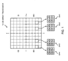
- FIG. 1 is a diagram showing a two-dimensional (2D) array transducer 10 of an ultrasound diagnostic apparatus of a preferred embodiment of the present invention.
- the 2D array transducer 10 is formed by two-dimensionally arranging a plurality of transducer elements.
- a plurality of transducer elements are two-dimensionally arranged in a vertical direction and a lateral direction, and a transducer surface of the 2D array transducer 10 is formed in a square shape as shown in FIG. 1 .
- the plurality of transducer elements may be two-dimensionally arranged in a circular shape so that the transducer surface of the 2D array transducer 10 is formed in a circular shape.
- the 2D array transducer 10 is divided into a plurality of sub-arrays.
- each of a plurality of squares separated in a lattice shape by a dotted line represents a sub-array.
- FIG. 1 shows in an enlarged manner four sub-arrays SA1 - SA4 as representative sub-arrays.
- Each sub-array comprises a plurality of transducer elements.
- each sub-array comprises nine transducer elements.
- nine squares arranged in a lattice shape in each sub-array of SA1 - SA4 represent nine transducer elements.
- the 2D array transducer 10 is segmented into a plurality of transducer regions.
- four regions (quadrants) of (I) - (IV) segmented by x-axis and y-axis of a dot-and-chain line represent four transducer regions.
- each of the transducer regions (I) - (IV) comprises 25 sub-arrays.
- FIG. 1 merely exemplifies one configuration for the preferred embodiment of the present invention, and the number of transducer elements in each sub-array and the number of sub-arrays in each transducer region are not limited to those in the example configuration of FIG. 1 .
- a plurality of transducer elements of the 2D array transducer 10 are electronically controlled, and, with this configuration, the ultrasound beam is two-dimensionally scanned and three-dimensional echo data are collected.
- an amount of delay (delay time) corresponding to each transducer element is set. For example, a transmitted signal which is delayed by the amount of delay corresponding to each transducer element is supplied to the transducer element, and a transmission beam is formed by a plurality of transducer elements of the 2D array transducer 10.
- the reception signals of a plurality of transducer elements of the 2D array transducer 10 are added, to form a reception signal along the reception beam.
- the delay process corresponding to each sub-array is executed based on a delay pattern defining, for each sub-array, an amount of delay for each of the plurality of transducer elements belonging to the sub-array.
- a common delay pattern is set for a plurality of sub-arrays belonging to the transducer region.
- a common delay pattern is set for the sub-array SA1 and the sub-array SA2.
- the letters assigned to the transducer elements in the sub-arrays SA1 and SA2 indicate the amounts of delay for the transducer elements, and the same letter represents the same amount of delay.
- the arrangement pattern of the letters in the sub-array SA1 and the arrangement pattern of the letters in the sub-array SA2 match each other. In other words, the arrangement pattern of the amounts of delay for the plurality of transducer elements in the sub-array SA1 and the arrangement pattern of the amounts of delay for the plurality of transducer elements in the sub-array SA2 match each other.
- a virtual plane is correlated to each of the plurality of transducer regions, and, for each transducer region, a common delay pattern is set based on the correlated virtual plane.
- a second order approximation equation of a delay time ⁇ for the plurality of transducer elements of the 2D array transducer 10 can be split into a term S which depends on steering and a term F which depends on focus.
- the delay time ⁇ can be represented as follows as a quadratic function of coordinates x and y.
- ⁇ c S - F 1
- S x ⁇ sin ⁇ x + y ⁇ cos ⁇ x ⁇ sin ⁇ y 2
- F / 2 ⁇ f x 2 + y 2 - S 2 3
- c the velocity of sound
- ⁇ x a steering angle in the x direction
- ⁇ y a steering angle in the y direction
- f a focus distance (depth).
- F the focus-dependent term
- ⁇ cos ⁇ x ⁇ sin ⁇ y
- ⁇ c becomes a linear equation of a plane.
- the slopes of the plane in the x direction and the y direction are ⁇ and ⁇ , which are known and related to steering. Because the function is a linear function, a difference in delay time between transducer elements is a constant proportional to the slopes ⁇ and ⁇ , and the delay patterns of all sub-arrays in the 2D array transducer 10 are set identical to each other. However, in this case, the focus distance f is infinity.
- slopes a i and b i are determined for each transducer region.
- the index i represents the numbers 1 - 4 of transducer regions (for example, I - IV in FIG. 1 ).
- Equation (5) the slopes of a plane a i and b i must be determined for each transducer region.
- the slopes a i and b i can be determined by setting a regression plane by the least squares method using Equations (3) and (5).
- the slopes a i and b i can be calculated by the following equations.
- the slops a i and b i may be determined by iterative numerical calculations, without the use of Equations (7) and (8).
- a common delay pattern is set for a plurality of sub-arrays in each transducer region as described above, and an amount of sub-delay is set for each transducer element according to the delay pattern.
- an individual amount of main delay is set for each of the plurality of sub-arrays.
- FIG. 2 is a diagram for explaining the amount of sub-delay and the amount of main delay, and is a conceptual diagram showing setting of the amount of delay for the transducer region (I) and the transducer region (III) of FIG. 1 .
- the horizontal axis represents a position of the transducer element, and a plurality of sub-arrays are arranged along the horizontal axis direction, with a width of the sub-array being a constant sub-array width.
- the vertical axis of FIG. 2 represents a magnitude of the amount of delay (delay time).
- a common delay pattern is set for the plurality of sub-arrays in each transducer region. Because of this, in FIG. 2 , an amount of sub-delay having a common slope (inclination) is set for the plurality of sub-arrays belonging to, for example, the transducer region (I).
- an individual amount of main delay is set for each of the plurality of sub-arrays.
- a sum of the amount of main delay and the amount of sub-delay is set as the amount of delay for each transducer element.
- the amount of delay obtained as a sum of the amount of main delay and the amount of sub-delay is set to approach an ideal delay curve.
- a curve shown with a dot-and-chain line represents the ideal delay line.
- the amount of main delay and the amount of sub-delay are suitably adjusted such that the delay pattern of the stairs-shape obtained as a sum of the amounts of delay is along the ideal delay curve. With this configuration, degradation of the beam characteristic can be inhibited.
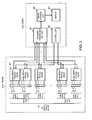
- FIG. 3 is a diagram showing the overall structure of an ultrasound diagnostic apparatus of the present embodiment.
- the ultrasound diagnostic apparatus of FIG. 3 comprises a probe 100 and a body 200, and the probe 100 and the body 200 are connected to each other via a cable.
- the probe 100 comprises the 2D array transducer 10 (refer to FIG. 1 ).
- the 2D array transducer 10 is constructed by two-dimensionally arranging the plurality of transducer elements 12.
- the 2D array transducer 10 is divided into a plurality of sub-arrays 1 ⁇ n and segmented into a plurality of transducer regions I ⁇ IV.
- a sub-array processor 20 is provided for each of the plurality of sub-arrays 1 ⁇ n.
- the sub-array processor 20 executes a delay process corresponding to the sub-array. In the delay process, the delay pattern which is set for each sub-array is used.
- the device body 200 comprises a transmitting/receiving unit 30.
- the transmitting/receiving unit 30 outputs a transmitted signal to which a delay process for individual amount of main delay for each sub-array is applied to each of the plurality of sub-array processors 20.
- the sub-array processor 20 applies a delay process to the transmitted signal by the amount of sub-delay corresponding to each transducer element 12 based on the delay pattern, and outputs the transmitted signal to each transducer element 12. In this manner, the transmitted signal to which the delay process is applied is supplied to the plurality of transducer elements 12 of the 2D array transducer 10, and the transmission beam is formed.
- each sub-array processor 20 applies a delay process on the reception signal obtained from each transducer element 12 based on the delay pattern, and adds the reception signals after the delay process, obtained from the plurality of transducer elements 12 belonging to the sub-array.
- the reception signal to which the addition process is applied for each sub-array processor 20 is sent to the transmitting/receiving unit 30.
- the transmitting/receiving unit 30 applies a delay process by an individual amount of main delay for each sub-array processor 20 to the reception signal obtained from each sub-array processor 20, and adds the reception signals after the delay process, obtained from the plurality of sub-array processors 20. In this manner, the reception signals obtained from the plurality of transducer elements 12 of the 2D array transducer 10 are collected, and echo data along the reception beam are obtained.
- the delay pattern used in transmission and the delay pattern used in reception may be a common pattern or may be different delay patterns between transmission and reception.
- the amount of main delay related to each of the plurality of sub-array processors 20 may be suitably controlled, to obtain echo data while changing the focus depth of the reception beam. In other words, the amount of main delay may be controlled to achieve a reception dynamic focus.
- An image-forming unit 40 forms image data based on echo data obtained along a plurality of reception beams.
- An ultrasound image corresponding to the image data is displayed on a display 50.
- the ultrasound beam is two-dimensionally scanned and echo data are three-dimensionally collected, and a three-dimensional ultrasound image is formed.
- a two-dimensional ultrasound image may be formed.
- a controller 60 integrally controls each unit of the ultrasound diagnostic apparatus of FIG. 3 .
- the controller 60 outputs control data for setting the delay pattern to the plurality of sub-array processors 20.
- a common delay pattern is set for a plurality of sub-arrays in each transducer region. Because of this, the controller 60 may output the same control data to the plurality of sub-arrays processors 20 belonging to the same transducer region. For example, common control data are output to a plurality of sub-array processors 20 belonging to the region I. Therefore, the controller 60 may output control data of a number corresponding to the number of transducer regions (for example, four).
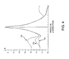
- FIG. 4 is a diagram showing a comparison result related to precision of the beamforming.
- FIG. 4 shows a beam characteristic in the x direction by a sound field simulation.
- the horizontal axis of FIG. 4 shows an angle in the x direction and the vertical axis represents an intensity of the sound field.
- FIG. 4 shows comparison results of three patterns related to the delay control.
- a waveform 72 represents a sound field characteristic in a case where the amount of delay is set for each transducer element while the focus distance is set to infinity and only the steering is considered (refer to Equation (4)).
- a waveform 74 represents a sound field characteristic when the amount of delay is set for each transducer element according to an ideal curve.
- a waveform 70 represents a sound field characteristic resulting from the configuration of the present embodiment.
- the waveform 70 represents a sound field characteristic when a common delay pattern is set for a plurality of sub-arrays in each transducer region, and an individual amount of main delay is set for each of the plurality of sub-arrays.
- the grating lobe is desirably small.
- the waveform 74 because the amount of delay is set for each transducer element according to the ideal curve, the grating lobe is the smallest, and superior beamforming precision is achieved.
- the beam control is a simplified control which sets the focus distance to infinity and considers only the steering, the grating lobe is the largest and the beamforming precision is inferior.
- the waveform 70 which is the sound field resulting from the configuration of the present embodiment, in contrast, has a smaller grating lobe compared to the waveform 72, and the grating lobe is inhibited to a level very close to that of the waveform 74.
- the waveform 74 is the sound field characteristic when the amount of delay is set for each transducer element according to the ideal curve. However, in order to set the amount of delay for each transducer element, a huge amount of information for the amount of delay is required. On the other hand, in the waveform 70, which is the sound field characteristic resulting from the configuration of the present embodiment, because the only requirement is to set a common delay pattern to the plurality of sub-arrays in each transducer region, the amount of information for the amount of delay can be maintained at a low level. For example, if the individual delay pattern is to be set for each of 164 sub-arrays, 164 delay patterns would be required, but in the present embodiment, 4 delay patterns corresponding to the 4 transducer regions may be set. In other words, the number of delay patterns can be dramatically reduced from 164 to 4.
- the precision of the beamforming can be maintained while reducing the number of delay patterns.
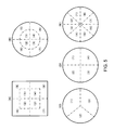
- FIG. 5 is a diagram showing various segmenting patterns of the transducer regions.
- patterns (A) - (E) squares and circles surrounded by solid lines represent a transducer surface of the 2D array transducer, and a dot-and-chain line drawn within the transducer surface represents a boundary of the transducer region.
- the 2D array transducer is segmented into a plurality of transducer regions by a virtual boundary radially extending from the center of the transducer surface, and is further segmented, as necessary, into a plurality of transducer regions by a virtual boundary which is set to surround the center of the transducer surface.
- pattern (A) a square transducer surface is segmented into 8 transducer regions (1) - (8).
- pattern (B) a circular transducer surface is segmented into 8 transducer regions (1) - (8).
- patterns (C) - (E) show example segmenting patterns for a circular transducer surface.
- segmenting patterns can be employed for the transducer regions, and segmenting patterns other than the segmenting patterns shown in FIGs. 1 and 5 may be used.
Landscapes
- Engineering & Computer Science (AREA)
- Physics & Mathematics (AREA)
- Radar, Positioning & Navigation (AREA)
- Remote Sensing (AREA)
- Acoustics & Sound (AREA)
- Health & Medical Sciences (AREA)
- Computer Networks & Wireless Communication (AREA)
- General Physics & Mathematics (AREA)
- Life Sciences & Earth Sciences (AREA)
- Multimedia (AREA)
- Nuclear Medicine, Radiotherapy & Molecular Imaging (AREA)
- Medical Informatics (AREA)
- Gynecology & Obstetrics (AREA)
- Pathology (AREA)
- Radiology & Medical Imaging (AREA)
- Biomedical Technology (AREA)
- Heart & Thoracic Surgery (AREA)
- Biophysics (AREA)
- Molecular Biology (AREA)
- Surgery (AREA)
- Animal Behavior & Ethology (AREA)
- General Health & Medical Sciences (AREA)
- Public Health (AREA)
- Veterinary Medicine (AREA)
- Ultra Sonic Daignosis Equipment (AREA)
- Investigating Or Analyzing Materials By The Use Of Ultrasonic Waves (AREA)
Applications Claiming Priority (1)
| Application Number | Priority Date | Filing Date | Title |
|---|---|---|---|
| JP2009169817A JP5315153B2 (ja) | 2009-07-21 | 2009-07-21 | 超音波診断装置 |
Publications (1)
| Publication Number | Publication Date |
|---|---|
| EP2284566A1 true EP2284566A1 (de) | 2011-02-16 |
Family
ID=42984084
Family Applications (1)
| Application Number | Title | Priority Date | Filing Date |
|---|---|---|---|
| EP10006737A Ceased EP2284566A1 (de) | 2009-07-21 | 2010-06-29 | Diagnostisches Ultraschallgerät |
Country Status (4)
| Country | Link |
|---|---|
| US (1) | US9146306B2 (de) |
| EP (1) | EP2284566A1 (de) |
| JP (1) | JP5315153B2 (de) |
| CN (1) | CN101961249B (de) |
Cited By (1)
| Publication number | Priority date | Publication date | Assignee | Title |
|---|---|---|---|---|
| WO2014182567A1 (en) * | 2013-05-08 | 2014-11-13 | General Electric Company | Ultrasound probe with dynamic focus and associated systems and methods |
Families Citing this family (10)
| Publication number | Priority date | Publication date | Assignee | Title |
|---|---|---|---|---|
| JP5664364B2 (ja) * | 2011-03-11 | 2015-02-04 | セイコーエプソン株式会社 | 超音波センサーおよび電子機器 |
| KR101460692B1 (ko) | 2011-06-09 | 2014-11-13 | 삼성전자주식회사 | 2차원 트랜스듀서-어레이를 구동시키는 장치, 의료영상시스템 및 2차원 트랜스듀서-어레이를 구동시키는 방법 |
| JP5892745B2 (ja) * | 2011-08-18 | 2016-03-23 | 株式会社東芝 | 超音波診断装置 |
| BR112014006480A2 (pt) * | 2011-09-22 | 2017-03-28 | Koninklijke Philips Nv | dispositivo de ultrassom e meio legível em computador para um dispositivo de obtenção de imagem de ultrassom |
| JP2014168500A (ja) * | 2013-03-01 | 2014-09-18 | Hitachi Aloka Medical Ltd | 超音波診断装置 |
| JP6305752B2 (ja) * | 2013-12-17 | 2018-04-04 | キヤノンメディカルシステムズ株式会社 | 超音波診断装置及び超音波プローブ |
| US10806429B2 (en) * | 2015-08-07 | 2020-10-20 | Hitachi, Ltd. | Ultrasonic imaging device and ultrasonic probe |
| JP6059782B1 (ja) * | 2015-10-01 | 2017-01-11 | 株式会社日立製作所 | 超音波診断装置及び遅延データ生成方法 |
| CN105997146A (zh) * | 2016-06-27 | 2016-10-12 | 麦克思商务咨询(深圳)有限公司 | 超声波传感器 |
| EP3966592B1 (de) | 2019-05-06 | 2025-04-23 | Koninklijke Philips N.V. | Verfahren und systeme zur kodierung und dekodierung von hochfrequenzdaten |
Citations (5)
| Publication number | Priority date | Publication date | Assignee | Title |
|---|---|---|---|---|
| EP0430450A2 (de) * | 1989-11-28 | 1991-06-05 | Hewlett-Packard Company | 2-Dimensionales, mit phasengesteuertem Array ausgestattetes Ultraschallabbildungssystem mit verteilter Phasierung |
| JP2000033087A (ja) | 1998-05-28 | 2000-02-02 | Hewlett Packard Co <Hp> | グル―プ内プロセッサを有するフェ―ズドアレイ音響装置 |
| WO2005019856A1 (en) * | 2003-08-25 | 2005-03-03 | Koninklijke Philips Electronics, N.V. | Transmit apodization control for microbeamformers |
| US20050243812A1 (en) * | 2004-04-28 | 2005-11-03 | Siemens Medical So.Utions Usa, Inc. | Dynamic sub-array mapping systems and methods for ultrasound imaging |
| JP2008514335A (ja) | 2004-09-30 | 2008-05-08 | コーニンクレッカ フィリップス エレクトロニクス エヌ ヴィ | マイクロビーム形成を行うトランスデューサの構造 |
Family Cites Families (22)
| Publication number | Priority date | Publication date | Assignee | Title |
|---|---|---|---|---|
| JPS6152864A (ja) * | 1984-08-24 | 1986-03-15 | 株式会社日立製作所 | 超音波受波整相回路 |
| JPH02182245A (ja) * | 1989-01-09 | 1990-07-16 | Fuji Electric Co Ltd | 超音波診断装置の送受信装置 |
| JP2961903B2 (ja) * | 1991-02-07 | 1999-10-12 | 株式会社日立製作所 | 超音波3次元撮像装置 |
| DE4405504B4 (de) * | 1994-02-21 | 2008-10-16 | Siemens Ag | Verfahren und Vorrichtung zum Abbilden eines Objekts mit einem 2-D-Ultraschallarray |
| US5784336A (en) * | 1996-11-18 | 1998-07-21 | Furuno Diagnostics America, Inc. | Delay scheme and apparatus for focussing the transmission and reception of a summed ultrasonic beam |
| JP4090664B2 (ja) | 2000-04-07 | 2008-05-28 | 株式会社日立メディコ | 超音波診断装置 |
| JP2003290228A (ja) * | 2002-03-29 | 2003-10-14 | Ge Medical Systems Global Technology Co Llc | 2次元アレイ超音波探触子の駆動方法および超音波診断装置 |
| JP2004089311A (ja) * | 2002-08-30 | 2004-03-25 | Fuji Photo Film Co Ltd | 超音波送受信装置 |
| JP2004105257A (ja) * | 2002-09-13 | 2004-04-08 | Fuji Photo Film Co Ltd | 超音波送受信装置 |
| JP4386683B2 (ja) * | 2002-09-30 | 2009-12-16 | 富士フイルム株式会社 | 超音波送受信装置及び超音波送受信方法 |
| JP3977827B2 (ja) | 2003-06-25 | 2007-09-19 | アロカ株式会社 | 超音波診断装置 |
| EP1491913B1 (de) * | 2003-06-25 | 2006-09-27 | Aloka Co. Ltd. | Diagnostische ultraschall-bildgebende Vorrichtung mit einem 2D Schallkopf mit variablen Subarrays |
| JP3977826B2 (ja) * | 2003-06-25 | 2007-09-19 | アロカ株式会社 | 超音波診断装置 |
| DE602004002806T2 (de) * | 2003-06-25 | 2007-08-23 | Aloka Co. Ltd., Mitaka | Diagnostische ultraschall-bildgebende Vorrichtung mit 2D Schallkopf mit variablen Subarray-Mustern |
| JP4495430B2 (ja) * | 2003-09-26 | 2010-07-07 | パナソニック株式会社 | 超音波診断装置 |
| JP4557575B2 (ja) * | 2004-03-25 | 2010-10-06 | 株式会社東芝 | 超音波診断装置 |
| JP2005342194A (ja) * | 2004-06-03 | 2005-12-15 | Toshiba Corp | 超音波診断装置 |
| US20090306510A1 (en) * | 2005-06-17 | 2009-12-10 | Kunio Hashiba | Ultrasound Imaging Apparatus |
| US7775982B2 (en) * | 2006-12-15 | 2010-08-17 | General Electric Company | Method and system for sub-aperture processing |
| EP1936404B1 (de) | 2006-12-18 | 2008-12-10 | Aloka Co., Ltd. | Diagnostisches Ultraschallgerät |
| US7798967B2 (en) * | 2006-12-19 | 2010-09-21 | Aloka Co., Ltd. | Ultrasound diagnosis apparatus |
| JP2008229096A (ja) * | 2007-03-22 | 2008-10-02 | Toshiba Corp | 超音波診断装置 |
-
2009
- 2009-07-21 JP JP2009169817A patent/JP5315153B2/ja active Active
-
2010
- 2010-06-29 EP EP10006737A patent/EP2284566A1/de not_active Ceased
- 2010-06-30 US US12/827,099 patent/US9146306B2/en active Active
- 2010-07-20 CN CN201010234562.4A patent/CN101961249B/zh active Active
Patent Citations (6)
| Publication number | Priority date | Publication date | Assignee | Title |
|---|---|---|---|---|
| EP0430450A2 (de) * | 1989-11-28 | 1991-06-05 | Hewlett-Packard Company | 2-Dimensionales, mit phasengesteuertem Array ausgestattetes Ultraschallabbildungssystem mit verteilter Phasierung |
| JP2000033087A (ja) | 1998-05-28 | 2000-02-02 | Hewlett Packard Co <Hp> | グル―プ内プロセッサを有するフェ―ズドアレイ音響装置 |
| US6126602A (en) * | 1998-05-28 | 2000-10-03 | Agilent Technologies, Inc. | Phased array acoustic systems with intra-group processors |
| WO2005019856A1 (en) * | 2003-08-25 | 2005-03-03 | Koninklijke Philips Electronics, N.V. | Transmit apodization control for microbeamformers |
| US20050243812A1 (en) * | 2004-04-28 | 2005-11-03 | Siemens Medical So.Utions Usa, Inc. | Dynamic sub-array mapping systems and methods for ultrasound imaging |
| JP2008514335A (ja) | 2004-09-30 | 2008-05-08 | コーニンクレッカ フィリップス エレクトロニクス エヌ ヴィ | マイクロビーム形成を行うトランスデューサの構造 |
Cited By (3)
| Publication number | Priority date | Publication date | Assignee | Title |
|---|---|---|---|---|
| WO2014182567A1 (en) * | 2013-05-08 | 2014-11-13 | General Electric Company | Ultrasound probe with dynamic focus and associated systems and methods |
| US9239375B2 (en) | 2013-05-08 | 2016-01-19 | General Electric Company | Ultrasound probe with dynamic focus and associated systems and methods |
| CN105339808A (zh) * | 2013-05-08 | 2016-02-17 | 通用电气公司 | 采用动态聚焦的超声探头以及关联系统和方法 |
Also Published As
| Publication number | Publication date |
|---|---|
| US9146306B2 (en) | 2015-09-29 |
| CN101961249B (zh) | 2014-04-02 |
| JP5315153B2 (ja) | 2013-10-16 |
| CN101961249A (zh) | 2011-02-02 |
| JP2011019858A (ja) | 2011-02-03 |
| US20110021921A1 (en) | 2011-01-27 |
Similar Documents
| Publication | Publication Date | Title |
|---|---|---|
| EP2284566A1 (de) | Diagnostisches Ultraschallgerät | |
| US11391838B2 (en) | Ultrasound transducer arrays with variable patch geometries | |
| US5902241A (en) | Large-aperture imaging using transducer array with adaptive element pitch control | |
| US5027820A (en) | Device for the three-dimensional focusing of an ultrasonic beam | |
| JP4675444B2 (ja) | トランスデューサを多重化する装置及び方法 | |
| EP2867697B1 (de) | In verschiedenen ultraschallsystemen betreibbare zweidimensionale ultraschall-wandlergruppen | |
| EP2287631A1 (de) | Ultraschalldiagnosevorrichtung | |
| US8202222B2 (en) | Equal phase two-dimensional array probe | |
| JP6960938B2 (ja) | 1次元パッチを有する2次元超音波アレイトランスデューサ | |
| EP3791204B1 (de) | Ultraschallbildgebung mit komprimierter erfasung und zugehörige vorrichtungen, systeme und verfahren | |
| US10304226B2 (en) | Ultrasound focal zone system and method | |
| CN111050664B (zh) | 超声波诊断装置以及发送控制方法 | |
| EP3191868B1 (de) | Zweidimensionale ultraschallwandleranordnung mit einem nicht rechteckigen aktiven erfassungsbereich | |
| US8506484B2 (en) | Ultrasonic imaging device | |
| CN100455268C (zh) | 超声波诊断装置 | |
| JP2011050490A (ja) | 超音波診断装置 |
Legal Events
| Date | Code | Title | Description |
|---|---|---|---|
| PUAI | Public reference made under article 153(3) epc to a published international application that has entered the european phase |
Free format text: ORIGINAL CODE: 0009012 |
|
| AK | Designated contracting states |
Kind code of ref document: A1 Designated state(s): AL AT BE BG CH CY CZ DE DK EE ES FI FR GB GR HR HU IE IS IT LI LT LU LV MC MK MT NL NO PL PT RO SE SI SK SM TR |
|
| AX | Request for extension of the european patent |
Extension state: BA ME RS |
|
| RAP1 | Party data changed (applicant data changed or rights of an application transferred) |
Owner name: HITACHI ALOKA MEDICAL, LTD. |
|
| 17P | Request for examination filed |
Effective date: 20110810 |
|
| 17Q | First examination report despatched |
Effective date: 20111122 |
|
| STAA | Information on the status of an ep patent application or granted ep patent |
Free format text: STATUS: THE APPLICATION HAS BEEN REFUSED |
|
| 18R | Application refused |
Effective date: 20140210 |