EP2284516B1 - Probenaufnahmegerät für Elementaranalysevorrichtungen - Google Patents
Probenaufnahmegerät für Elementaranalysevorrichtungen Download PDFInfo
- Publication number
- EP2284516B1 EP2284516B1 EP10170555.6A EP10170555A EP2284516B1 EP 2284516 B1 EP2284516 B1 EP 2284516B1 EP 10170555 A EP10170555 A EP 10170555A EP 2284516 B1 EP2284516 B1 EP 2284516B1
- Authority
- EP
- European Patent Office
- Prior art keywords
- sampler
- sample
- sample housing
- gas
- isolation valve
- Prior art date
- Legal status (The legal status is an assumption and is not a legal conclusion. Google has not performed a legal analysis and makes no representation as to the accuracy of the status listed.)
- Active
Links
Images


Classifications
-
- G—PHYSICS
- G01—MEASURING; TESTING
- G01N—INVESTIGATING OR ANALYSING MATERIALS BY DETERMINING THEIR CHEMICAL OR PHYSICAL PROPERTIES
- G01N30/00—Investigating or analysing materials by separation into components using adsorption, absorption or similar phenomena or using ion-exchange, e.g. chromatography or field flow fractionation
- G01N30/02—Column chromatography
- G01N30/04—Preparation or injection of sample to be analysed
- G01N30/24—Automatic injection systems
-
- G—PHYSICS
- G01—MEASURING; TESTING
- G01N—INVESTIGATING OR ANALYSING MATERIALS BY DETERMINING THEIR CHEMICAL OR PHYSICAL PROPERTIES
- G01N1/00—Sampling; Preparing specimens for investigation
- G01N1/28—Preparing specimens for investigation including physical details of (bio-)chemical methods covered elsewhere, e.g. G01N33/50, C12Q
- G01N1/34—Purifying; Cleaning
-
- G—PHYSICS
- G01—MEASURING; TESTING
- G01N—INVESTIGATING OR ANALYSING MATERIALS BY DETERMINING THEIR CHEMICAL OR PHYSICAL PROPERTIES
- G01N31/00—Investigating or analysing non-biological materials by the use of the chemical methods specified in the subgroup; Apparatus specially adapted for such methods
- G01N31/12—Investigating or analysing non-biological materials by the use of the chemical methods specified in the subgroup; Apparatus specially adapted for such methods using combustion
-
- G—PHYSICS
- G01—MEASURING; TESTING
- G01N—INVESTIGATING OR ANALYSING MATERIALS BY DETERMINING THEIR CHEMICAL OR PHYSICAL PROPERTIES
- G01N35/00—Automatic analysis not limited to methods or materials provided for in any single one of groups G01N1/00 - G01N33/00; Handling materials therefor
- G01N35/10—Devices for transferring samples or any liquids to, in, or from, the analysis apparatus, e.g. suction devices, injection devices
- G01N35/1095—Devices for transferring samples or any liquids to, in, or from, the analysis apparatus, e.g. suction devices, injection devices for supplying the samples to flow-through analysers
- G01N35/1097—Devices for transferring samples or any liquids to, in, or from, the analysis apparatus, e.g. suction devices, injection devices for supplying the samples to flow-through analysers characterised by the valves
-
- G—PHYSICS
- G01—MEASURING; TESTING
- G01N—INVESTIGATING OR ANALYSING MATERIALS BY DETERMINING THEIR CHEMICAL OR PHYSICAL PROPERTIES
- G01N1/00—Sampling; Preparing specimens for investigation
- G01N1/28—Preparing specimens for investigation including physical details of (bio-)chemical methods covered elsewhere, e.g. G01N33/50, C12Q
- G01N1/44—Sample treatment involving radiation, e.g. heat
-
- G—PHYSICS
- G01—MEASURING; TESTING
- G01N—INVESTIGATING OR ANALYSING MATERIALS BY DETERMINING THEIR CHEMICAL OR PHYSICAL PROPERTIES
- G01N1/00—Sampling; Preparing specimens for investigation
- G01N1/02—Devices for withdrawing samples
- G01N1/22—Devices for withdrawing samples in the gaseous state
- G01N1/2247—Sampling from a flowing stream of gas
- G01N2001/2267—Sampling from a flowing stream of gas separating gas from liquid, e.g. bubbles
-
- G—PHYSICS
- G01—MEASURING; TESTING
- G01N—INVESTIGATING OR ANALYSING MATERIALS BY DETERMINING THEIR CHEMICAL OR PHYSICAL PROPERTIES
- G01N30/00—Investigating or analysing materials by separation into components using adsorption, absorption or similar phenomena or using ion-exchange, e.g. chromatography or field flow fractionation
- G01N30/02—Column chromatography
- G01N2030/022—Column chromatography characterised by the kind of separation mechanism
- G01N2030/025—Gas chromatography
-
- G—PHYSICS
- G01—MEASURING; TESTING
- G01N—INVESTIGATING OR ANALYSING MATERIALS BY DETERMINING THEIR CHEMICAL OR PHYSICAL PROPERTIES
- G01N30/00—Investigating or analysing materials by separation into components using adsorption, absorption or similar phenomena or using ion-exchange, e.g. chromatography or field flow fractionation
- G01N30/02—Column chromatography
- G01N30/04—Preparation or injection of sample to be analysed
- G01N30/06—Preparation
- G01N30/12—Preparation by evaporation
- G01N2030/125—Preparation by evaporation pyrolising
-
- G—PHYSICS
- G01—MEASURING; TESTING
- G01N—INVESTIGATING OR ANALYSING MATERIALS BY DETERMINING THEIR CHEMICAL OR PHYSICAL PROPERTIES
- G01N30/00—Investigating or analysing materials by separation into components using adsorption, absorption or similar phenomena or using ion-exchange, e.g. chromatography or field flow fractionation
- G01N30/02—Column chromatography
- G01N30/88—Integrated analysis systems specially adapted therefor, not covered by a single one of the groups G01N30/04 - G01N30/86
- G01N2030/8809—Integrated analysis systems specially adapted therefor, not covered by a single one of the groups G01N30/04 - G01N30/86 analysis specially adapted for the sample
- G01N2030/8859—Integrated analysis systems specially adapted therefor, not covered by a single one of the groups G01N30/04 - G01N30/86 analysis specially adapted for the sample inorganic compounds
-
- G—PHYSICS
- G01—MEASURING; TESTING
- G01N—INVESTIGATING OR ANALYSING MATERIALS BY DETERMINING THEIR CHEMICAL OR PHYSICAL PROPERTIES
- G01N30/00—Investigating or analysing materials by separation into components using adsorption, absorption or similar phenomena or using ion-exchange, e.g. chromatography or field flow fractionation
- G01N30/02—Column chromatography
- G01N30/62—Detectors specially adapted therefor
- G01N30/64—Electrical detectors
- G01N30/66—Thermal conductivity detectors
Definitions
- the present invention relates to a sampler for automatic elemental analyzers including a pyrolytic unit, particularly a sampler of the fully tight, sealed type.
- An elemental analyzer including a pyrolytic unit internally or aside, is an instrument intended for analyzing the elemental composition in samples of solid or liquid materials, usually accommodated in e.g. tin or silver cups using oxygen for combustion and carbon for pyrolytic reduction generating gas as reaction products.
- An elemental analyzer comprises a sampler for introducing the sample suitably prepared e.g. in said tin or silver cups or adsorbed in inert material if liquids into a combustion or pyrolytic reactor of the analyzer itself.
- the elemental analyzer further comprises a furnace in which reactor tubes for combustion (usually at temperatures higher than 900°C) or pyrolytic reaction (usually at temperatures between 1200- 1500°C or more) are accommodated for sample combustion or pyrolysis.
- Samples thus converted into a gas mixture flow through a trap to eventually eliminate water or acidic gas and a gas chromatography column which allows the gas to be time separated and then detected by a TCD for stand alone application providing element % result in the mixture; the separated gas can be further analyzed in their isotopic composition entering in continuous flow in an Isotopic Ratio Mass Spectrometer to provide Isotopic Ratio composition of the isotopes included in each element.
- a pneumatic circuit is provided capable of creating a continuous flow of carrier gas, for example Helium or Argon.
- samplers for elemental analyzers used in combustion or pyrolysis can contains traces of residual adsorbed gas, water, vapor or other compound present on the samples as they are, or resulting from pre-treatments or storage. These unwanted material can affect element % results in stand alone combustion and pyrolytic application and indeed isotopic ratio accuracy.
- the object of the present invention is therefore to provide a sampler suitable to eliminate air contamination affecting Nitrogen and Oxygen determination, all other environmental components and gas, vapor, volatile components adsorbed or present in the samples affecting results and to mitigate or at least partially overcome the drawbacks mentioned with reference to the samplers according to the known prior art.
- Another object of the present invention is to allows simultaneous preparation of the samples inside the sampler in the same conditions.
- a further object of the present invention is to allow simultaneous injection of equilibration liquid in the sampler housing for simultaneous equilibration of all samples included in the sampler.
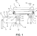
- an elemental analyzer is indicated with the reference number 100.
- An elemental analyzer is an instrument intended for analyzing the elemental composition of liquid or solid samples providing results as % of each element using a TCD Detector in stand alone or results as isotopic ratio using in series an isotopic ratio mass spectrometer IRMS.
- the elemental analyzer 100 comprises a sampler 200 whose task is to introduce the sample to be analyzed and generally filled in tin or silver cups into a system comprising a furnace 300 in which it is usually accommodated a reaction tube 350 and brought to a temperature of about 900 °C or more for combustion applications and between 1200°C - 1500 °C or more for pyrolytic applications, which is thus combusted in presence of Oxygen or converted by Carbon Reduction, providing a gas mixture suitable to be detected by the TCD in stand alone and/or the isotopic ratio mass spectrometer IRMS when this detector is interfaced.
- Gas species produced in the Combustion or Pyrolytic Reduction are coming out from the reaction tube and are flowing into a trap 360 to eliminate undesired acidic gases or water and are than time separated by gas chromatography to obtain peaks of single elements directly related to % composition or isotopic ratio determination.
- a control unit 500 drives the various components of the analyzer 100.
- the focus of the present invention is on the sampler 200.
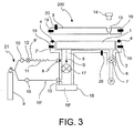
- the sampler 200 comprises a sample housing 2 suitable to accommodate one or more samples as sequence (not shown in the figures).
- the sample housing 2 is preferably delimited by a sample housing body 2' of the sampler 200.
- a sample carousel 1 is provided, on which the samples, generally sealed in tin or silver caps, are loaded.
- the sampler 200 comprises closure means suitable to reversibly seal the sample housing 2, so that, after the samples are accommodated, the closure means can be closed and the samples in the carousel 1 cannot be further contaminated by environmental agents due to the specific design granting full tightness.
- the closure means may comprise a plate 3 acting as a lid for the sample housing 2.
- Tightening means are provided in order to form a gastight enclosure when the lid 3 closes the sample housing 2.
- the tightening means comprise an O-ring 4 providing a gas tightness between the sample housing 2 and the external environment when the plate 3 rests on the sample housing body 2', thereby closing the sample housing 2.
- the whole design ensures an absolute "Zero Blank" for the environmental contamination as proved by sampling from the carousel without samples by using IRMS as supersensitive measure to the contamination by using the corresponding mass of the contaminating agent (e.g. mass of N 2 ).
- the sampler 200 further comprises a sample passage 5 for the passage of the samples loaded in the sample housing 2 into the analyzer.
- the sampler is connected or connectable to the analyzer 100 by means of a connector 18 provided with a connection opening 18'.
- the sample passage 5 is preferably located in the lower part of the sample housing 2, so to allow the samples to drop by gravity from the sample housing 2 to the analyzer through the connection opening 18' (see arrow S in figure 2 ).
- the carousel 1 is able to advance by discrete steps, for example pneumatic or electrical actuated, so to drop each individual sample to be analyzed sequentially from the carousel 1 and to bring it directly above the sample passage 5 at an appropriate time during the analysis cycle.
- the sampler 200 comprises means, such as vacuum system, for pumping environmental gases and vapours out of the sample housing 2 and means for heating the sample housing 2 itself and the one or more samples loaded therein.
- These pumping means may alternatively be included within the sampler or be externally located and connectable to the latter.
- the heating means preferably comprise a plurality of heaters 19, still more preferably inserted into the sample housing body 2', in such a manner that they are able to heat the sampler body, the carousel and in turn the sample cups and samples itself by heat conduction.
- the heating means may further comprise a temperature sensor 20, which may be in turn inserted in the sample housing body 2' and may be connected to the control unit 500. In this manner, the control unit 500 is capable of receiving a temperature signal from the temperature sensor 20 thereby controlling the heaters 19 so to maintain the temperature inside the sample housing 18 at a constant desired value.
- heaters 19 and temperature sensors 20 are also inserted into closure plate 3.
- the pumping means may comprise a pump P and are advantageously suitable to generate a vacuum inside the sample housing 2'. In this manner the atmospheric gases, water and tension volatile compound at the increased vapour temperature due to heat application will allow the process to work far more effectively.
- optimal conditions for the different variety of sample can be selected with gas pumped away from the sample housing 2, such that the isotopic composition accuracy can be improved and troublesome inconveniences limited.
- the sampler 200 comprises a pumping duct 6, preferably located in the lower part of the sample housing 2 to allow the fluid connection of the latter with the pump P.
- pump isolation valve means are provided.
- such pump isolation valve means include a pump isolation valve 7 operatively located between the pump P and the sample housing 2.
- the pump isolation valve 7 is configurable in at least an open configuration and in a close configuration. When the pump isolation valve 7 is in the open configuration, the pump P and the sample housing 2 are in fluid connection, so that gases in the sample housing can be evacuated by the pump P. Instead, when the pump isolation valve 7 is in the closed position, the sample housing 2 and the pump P are not in fluid communication, such that the sample housing is isolated from the pump P.
- the pump isolation valve 7 is of the ON/OFF type.
- the sampler 200 comprises a inert gas circuit 21.
- the sampler 200 is connected or connectable to said inert gas circuit 21.
- the inert gas circuit 21 comprises a flushing duct 8' which is connected or connectable to the sample passage 5 at a first gas port 8.
- the flushing duct 8' is further connected or connectable to a gas cylinder 9 suitable to accommodate pressurized inert gas, for example Helium or Argon. In this manner the inert gas is able to flow from the gas cylinder 9 to the sample housing 2 through the flushing duct 8'.
- the closure plate 3 comprises a gas vent 13 having a purge plug 14 which allows the reversible closure of the gas vent 13.
- the sample housing 2 can be purged from the atmospheric gases and the samples in the sample housing 2 can be maintained in an inert gas environment with a fully sealed enclosure.
- the heating means help the purge process of the Helium.
- Helium flows into the cups which are closed but not sealed.
- Adsorbed gas in geological material or hygroscopic cellulose as important examples as well other pre-treated samples, will release gas or water more efficiently helped by purge action of the most diffusive Helium and temperature application also helping dry sample to remain dry during an autorun full sequence.
- the flushing duct 8' comprises gas cylinder isolation valve means which are operatively interposed between the gas cylinder 9 and the sample housing 2, particularly, between the gas cylinder 9 and the sample passage 5.
- the gas cylinder isolation valve means preferably comprise a gas cylinder isolation valve 12 which is configurable in at least an open configuration, in which the gas cylinder 9 is in communication with the sample housing 2, particularly with the sample passage 5 which is connected with the sample housing 2, and a close position, in which the gas cylinder 9 is isolated from the sample passage.
- the gas cylinder isolation valve 12 is an ON/OFF type valve, such that the admission of the inert gas coming from the gas cylinder 9 into the sample passage 5 and the sample housing 2 can be switched on and off.
- the flushing duct 8' comprises gas restriction means 11 and a pressure regulator 12.
- the pressure regulator 10 has the function of controlling the rate of admission of the inert gas into the sample housing 2, whilst the gas restriction means have the function of slowing the gas flow into the sample housing 2.
- the inert gas circuit 21 comprise a carrier gas duct 15' connected or connectable to the gas cylinder 9 and connected or connectable to the sample passage 5, particularly at a second gas port 15, in such a manner that the pressurized gas form the gas cylinder 9 is capable of passing through the sample passage 5, particularly towards the connection opening 18'.
- the carrier gas duct 15' is operatively in parallel with the flushing duct 8'. Still more advantageously, the carrier gas duct 18' comprises a pressure regulator 16, such that the rate of admission of the inert gas into the sample passage 5 can be controlled.
- sample passage 5 comprises sampler isolation valve means, particularly a sampler isolation valve 17, located in the sample passage 5 itself between the first 8 and the second 15 gas ports, the latter gas port 15 being interposed between the sampler isolation valve 17 and the connection opening 18'.
- the sampler isolation valve 17 is configurable in at least an open configuration and in a close configuration.
- the sampler isolation valve is preferably a valve of the ON/OFF type. In this manner, the sampler isolation valve 17 allows the sampler 200 to be isolated from elemental analyzer, particularly a carrier gas circuit thereof (not shown in the figures), when the sampler is connected to the elemental analyzer.
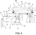
- sampler 200 is provided with an injection unit 22 which allows injection of liquids in the sample housing 2 inside the sampler 200.
- an injection unit 22 allows injection of liquids in the sample housing 2 inside the sampler 200.
- the known prior art requires a pre-treatment of the samples which are added with such liquids before being inserted into the sampler and usually are pre-treated one after the other.
- the injection unit 22 allows the liquid to be injected directly in the sample housing 2 of sampler 200 by a single injection for all the samples in the same condition without the need of removing the samples, thus the samples are treated substantially simultaneously and the results of the analysis are reliable.
- Example of analysis which requires the injection of liquids are: studies of paleoclimate, animal migration, forensic, food and flavour authentication, origin and diagenesis of organic material, complex organic materials such as feathers or keratin. In these cases it is necessary to equilibrate the samples with water at known isotopic composition.
- such equilibration treatment is carried out inside sampler 200.
- the injection unit 22 comprises an injection port, in fluid communication with the sample housing 2 and thus with the samples; a septum through which the liquid is injected in the injection port preferably by using a syringe; a septum holder.
- the liquid comprises water at known Isotope Ratio.
- Both the syringe and the septum may be chosen on the basis of the test to be performed. They may be of any suitable known type and thus they will be no further described.
- heaters 19 and temperature sensors 20 are provided both in the sample housing body 2' and into closure plate 3. Furthermore sampler 200 is provided with an injection unit 22.
- the apparatus is operated in a "degassing mode", in which the environmental gas contaminants (e.g Oxygen from air with different composition from Oxygen in the sample or water in hygroscopic material at different isotopic composition from Oxygen included for instance in Cellulose) are purged away; samples to be analyzed, filled into tin or silver cups closed but not fully tight, are degassed from sample adsorbed gas or dried sample from water or volatile material derived from prior pre-treatments (preparation).
- the environmental gas contaminants e.g Oxygen from air with different composition from Oxygen in the sample or water in hygroscopic material at different isotopic composition from Oxygen included for instance in Cellulose
- samples included in capsules are loaded into the sample housing 2, particularly into the carousel 1.
- the plate 3 acting as a lid, and the purge plug 14 are closed granting full tightness.
- the tank isolation valve 12 and the sampler isolation valve 17 are kept in the close configuration.
- the pump isolation valve 7 is opened, the pump P is activated and the heaters 19 are turned on. In this manner, the atmospheric gases, water vapor and other volatile material are removed from the samples by heating, and are pumped away from the sample housing 2.
- a second possible operating mode is a "purging mode", which takes place after atmospheric gases are purged from the sample housing 2, and the samples to be analyzed also purged from gas adsorbed, water and volatile vapor, according to the degassing mode.
- the pump isolation valve 7 and the sampler isolation valve 17 are kept closed, and the purge plug 14 is opened.
- the pressure regulators 10 and 16 are set to the each other closer pressure.
- the gas cylinder isolation valve 12 is opened, so that the inert gas passes through the sample housing 2 and vents out the atmospheric gases through the gas vent 13.
- the purge plug 14 is closed, the sampler isolation valve 17 is opened and the gas cylinder isolation valve 12 may be closed.
- a preferring operating mode provides that after the samples are heated .to the desired temperature, the liquid is injected by a syringe through the injection unit 22.
- sampler allows the samples to be maintained in an inert gas environment within a fully sealed enclosure, thus preventing contamination from any atmospheric gases.
- sampler allows the samples to be degassed from any residual gas adsorbed or unwanted vapour in the samples eliminated before they are actually introduced into the elemental analyzer for analysis.
- sampler according to the invention allows a simultaneous equilibration in a reduced time and an analytical sequential sampling of equilibrated samples.
- sampler of the invention allows to obtain a procedure which achieve the so called “Identical Treatment” (IT) for all the samples thus obtaining a repeatability of the analysis.
Landscapes
- Health & Medical Sciences (AREA)
- Life Sciences & Earth Sciences (AREA)
- Chemical & Material Sciences (AREA)
- Immunology (AREA)
- Analytical Chemistry (AREA)
- Biochemistry (AREA)
- General Health & Medical Sciences (AREA)
- General Physics & Mathematics (AREA)
- Physics & Mathematics (AREA)
- Pathology (AREA)
- Engineering & Computer Science (AREA)
- Molecular Biology (AREA)
- Combustion & Propulsion (AREA)
- Biomedical Technology (AREA)
- Sampling And Sample Adjustment (AREA)
- Investigating Or Analysing Biological Materials (AREA)
Claims (18)
- Sampler (200), insbesondere Sampler des abgedichteten völlig dichten Typs, für eine Elementaranalyseeinheit (100), umfassend:- ein Probengehäuse (2), welches dazu geeignet ist, eine Mehrzahl von zu analysierenden Proben aufzunehmen;- Verschlussmittel (3, 4), umfassend eine Verschlussplatte (3), welche als ein Deckel des Probengehäuses (2) wirkt und dazu geeignet ist, das Probengehäuse (2) zu öffnen und in einer abdichtenden Weise zu schließen, um die Proben darin aufzunehmen;- einen Probendurchgang (5) mit einer Verbindungöffnung (18') für den Durchtritt einer Probe aus dem Sampler (200) in die Analyseeinheit (100) durch die Verbindungsöffnung (18') und einem Sampler-Isolationsventil (17), welches in einer offenen Konfiguration und in einer geschlossenen Konfiguration zur Isolierung des Samplers (200) von der Elementaranalyseeinheit (100) konfigurierbar ist,- eine Pumpe (P),dadurch gekennzeichnet, dass der Sampler (200) Mittel (19) zum Erwärmen des Probengehäuses (2) und eine Regel-/Steuereinheit (500) umfasst, welche dazu eingerichtet ist, den Sampler in einer entgasenden Weise zu bedienen, wobei die Erwärmungsmittel (19) zum Entfernen von Umweltgasen, Wasserdampf und anderem volatilen Material von den Proben eingeschaltet werden, während die Pumpe (P) aktiviert ist, um die entfernten Umweltgase und Wasserdämpfe von dem Probengehäuse (2) weg zu pumpen.
- Sampler (200) nach dem vorhergehenden Anspruch, wobei die Pumpmittel (P) dazu geeignet sind, ein Vakuum in dem Probengehäuse (2) zu erzeugen.
- Sampler (200) nach Anspruch 1 oder 2, umfassend Pumpen-Isolationsventilmittel (7), welche zwischen den Pumpmitteln (P) und dem Probengehäuse (2) betriebsmäßig angeordnet sind, wobei die Pumpen-Isolationsventilmittel (7) in wenigstens einer offenen Konfiguration, in welcher die Pumpmittel (P) mit dem Probengehäuse (2) in Fluid-Verbindung sind, und einer geschlossenen Position konfigurierbar sind, in welcher das Probengehäuse (2) von den Pumpmitteln (P) fluidisch isoliert ist.
- Sampler (200) nach einem der vorhergehenden Ansprüche, umfassend eine Pumpleitung (6) für eine Fluid-Verbindung zwischen dem Probengehäuse (2) und den Pumpmitteln (P), wobei die Pumpleitung (6) in dem unteren Teil des Probengehäuses (2) angeordnet ist.
- Sampler (200) nach einem der vorhergehenden Ansprüche, wobei die Erwärmungsmittel umfassen:- eine Mehrzahl von Erwärmungselementen (19), welche in einen Probengehäusekörper (2') eingesetzt sind, welcher das Probengehäuse (2) begrenzt,- einen Temperatursensor (20), welcher in dem Probengehäusekörper (2') eingesetzt ist, welcher das Probengehäuse (2) begrenzt,wobei der Temperatursensor (20) mit einer Regel-/Steuereinheit (500) verbunden ist, welche dazu geeignet ist, die Erwärmungsmittel (19) zu regeln/steuern, um die Temperatur des Probengehäuses (2) bei einem im Wesentlichen konstanten Wert als eine Funktion der Temperatur zu halten, welche durch den Temperatursensor (20) ausgelesen wird.
- Sampler (200) nach einem der vorhergehenden Ansprüche, umfassend eine Spülleitung (8'), welche mit dem Probendurchgang (5) verbunden oder verbindbar ist und mit einem Gaszylinder (9) verbunden oder verbindbar ist, welcher dazu geeignet ist, unter Druck stehendes inertes Gas aufzunehmen, wobei die Spülleitung (8') mit dem Probengehäuse (2) derart in Fluid-Verbindung steht, dass das unter Druck stehende inerte Gas von dem Gaszylinder (9) in der Lage ist, durch das Probengehäuse (2) zu treten.
- Sampler (200) nach dem vorhergehenden Anspruch, wobei die Verschlussplatte (3) mit einer schließbaren Gaslüftung (13) derart bereitgestellt ist, dass Gase, welche durch das Probengehäuse (2) treten, ausgespült werden können, wenn die Gaslüftung (13) geöffnet ist.
- Sampler (200) nach dem vorhergehenden Anspruch, umfassend einen Spülstopfen (14), welcher dazu geeignet ist, die Gaslüftung (13) der Verschlussplatte (3) abzudichten.
- Sampler (200) nach einem der Ansprüche 6 bis 8, wobei die Spülleitung (8') Gaszylinder-Isolationsventilmittel (12) umfasst, welche zwischen dem Gaszylinder (9) und dem Probendurchgang (5) betriebsmäßig angeordnet sind, wobei die Gaszylinder-Isolationsventilmittel (12) in wenigstens einer offenen Konfiguration, in welcher der Gaszylinder (9) mit dem Probendurchgang in Verbindung steht, und einer geschlossenen Position konfigurierbar sind, in welcher der Gaszylinder (9) von dem Probendurchgang (5) isoliert ist.
- Sampler (200) nach einem der Ansprüche 6 bis 9, wobei die Spülleitung (8') Gasrückhaltemittel (11) und einen Druckregulator (10) umfasst, um einen Druck des inerten Gases zu regeln/steuern, wenn es durch die Spülleitung (8') strömt.
- Sampler (200) nach einem der Ansprüche 6 bis 10, umfassend eine Trägergasleitung (15'), welche den Probendurchgang (5) mit dem Gaszylinder (9) derart verbindet, dass das unter Druck stehende inerte Gas von dem Gaszylinder (9) in der Lage ist, durch die Verbindungsöffnung (18') des Probendurchgangs (5) zu treten, um in die Analyseeinheit (100) zu strömen.
- Sampler (200) nach dem vorhergehenden Anspruch, wobei die Trägergasleitung (15') parallel zu der Spülleitung (8') angeordnet ist.
- Sampler (200) nach Anspruch 11 oder 12, wobei die Trägergasleitung (15') einen Druckregulator (16) umfasst.
- Sampler (200) nach einem der Ansprüche 11 bis 13, wobei das Sampler-Isolationsventil (17) in dem Probendurchgang (5) zwischen einem ersten (8) und einem zweiten (15) Gasanschluss angeordnet ist, an welchen die Spülleitung (8') und die Trägergasleitung (15') jeweils mit dem Probendurchgang (5) verbunden sind.
- Sampler (200) nach einem der vorhergehenden Ansprüche, ferner umfassend eine Injektionseinheit (22), welche dazu geeignet ist, eine Flüssigkeit in das Probengehäuse (2) zu injizieren.
- Elementaranalyseeinheit (100), umfassend einen Sampler (200) nach einem der vorhergehenden Ansprüche.
- Verfahren zum Bedienen eines Samplers (200) für eine Elementaranalyseeinheit (100), umfassend die Schritte:- Bereitstellen eines Samplers (200) gemäß Ansprüchen 8 und 9 und, in einem Entgasungsmodus,- Beladen von Proben, welche in Kapseln umfasst sind, in das Probengehäuse (2),- nachfolgendes Schließen der Platte (3) und des Spülstopfens (14) des Samplers (200),- Halten des Gaszylinder-Isolationsventils (12) und des Sampler-Isolationsventils (17) in der geschlossenen Konfiguration,- in diesem Zustand, Öffnen des Pumpen-Isolationsventils (7), Aktivieren der Pumpe (P) und Einschalten der Erwärmungselemente (19), um dadurch die atmosphärischen Gase, Wasserdampf und andere volatile Materialien von den Proben durch Erwärmen zu entfernen, und Wegpumpen dieser aus dem Probengehäuse (2).
- Verfahren nach Anspruch 17, umfassend die Schritte eines Spülmodus, welcher stattfindet, nachdem die atmosphärischen Gase aus dem Probengehäuse (2) gespült wurden und nachdem die Proben von absorbiertem Gas, Wasser und volatilem Dampf gemäß dem Entgasungsmodus gereinigt wurden,
wobei die Spülmodusschritte umfassen:- Geschlossenhalten des Pumpen-Isolationsventils (7) und des Sampler-Isolationsventils (17) und Öffnen des Spülstopfens (14),- Öffnen des Gaszylinder-Isolationsventils (12), so dass inertes Gas durch das Probengehäuse (2) tritt und die atmosphärischen Gase durch die Gaslüftung (13) entlüftet,- wenn das Spülen abgeschlossen ist, Schließen des Spülstopfens (14) und Öffnen des Sampler-Isolationsventils (17).
Applications Claiming Priority (1)
| Application Number | Priority Date | Filing Date | Title |
|---|---|---|---|
| ITMI2009A001440A IT1395147B1 (it) | 2009-08-07 | 2009-08-07 | Campionatore per analizzatore elementare |
Publications (2)
| Publication Number | Publication Date |
|---|---|
| EP2284516A1 EP2284516A1 (de) | 2011-02-16 |
| EP2284516B1 true EP2284516B1 (de) | 2018-07-04 |
Family
ID=41719210
Family Applications (1)
| Application Number | Title | Priority Date | Filing Date |
|---|---|---|---|
| EP10170555.6A Active EP2284516B1 (de) | 2009-08-07 | 2010-07-23 | Probenaufnahmegerät für Elementaranalysevorrichtungen |
Country Status (3)
| Country | Link |
|---|---|
| US (1) | US8616073B2 (de) |
| EP (1) | EP2284516B1 (de) |
| IT (1) | IT1395147B1 (de) |
Families Citing this family (6)
| Publication number | Priority date | Publication date | Assignee | Title |
|---|---|---|---|---|
| US20140318275A1 (en) * | 2012-01-13 | 2014-10-30 | Shimadzu Corporation | Auto-sampler |
| CN104459016B (zh) * | 2014-09-25 | 2016-08-17 | 长沙开元仪器股份有限公司 | 一种元素测试仪 |
| CN105784459B (zh) * | 2016-03-15 | 2019-05-21 | 亚洲硅业(青海)有限公司 | 氯硅烷和多晶硅体表金属痕量杂质元素的前处理装置 |
| CN108196005B (zh) * | 2017-12-07 | 2020-07-24 | 中国科学院东北地理与农业生态研究所 | 一种有机液体样品中碳、氮、氢、硫含量的测定方法 |
| CN112730781A (zh) * | 2020-12-24 | 2021-04-30 | 北京林业大学 | 一种原位持续测定森林生态系统稳定水同位素值的系统 |
| CN115494140B (zh) * | 2021-06-17 | 2025-07-29 | 同方威视技术股份有限公司 | 进样装置、分析系统和检测擦拭纸的方法 |
Family Cites Families (5)
| Publication number | Priority date | Publication date | Assignee | Title |
|---|---|---|---|---|
| US4336721A (en) * | 1980-06-03 | 1982-06-29 | Hague International | Gas analyzer |
| DE4223116A1 (de) * | 1992-04-30 | 1993-11-04 | Mikrowellen Labor Systeme | Vorrichtung zur verdampfungsbehandlung von vorzugsweise fluessigen stoffen, insbesondere reagenzstoffen, oder zum aufbereiten oder analysieren von probenmaterial |
| US5866072A (en) * | 1996-02-26 | 1999-02-02 | Cds Analytical, Inc. | Analytical pyrolysis autosampler |
| US5981290A (en) * | 1997-04-07 | 1999-11-09 | The United States Of America As Represented By The Secretary Of Transportation | Microscale combustion calorimeter |
| ITTO20010175U1 (it) * | 2001-09-19 | 2003-03-19 | Eurovector S P A | Campionatore, particolarmente per analizzatori elementari automatici. |
-
2009
- 2009-08-07 IT ITMI2009A001440A patent/IT1395147B1/it active
-
2010
- 2010-07-23 EP EP10170555.6A patent/EP2284516B1/de active Active
- 2010-08-03 US US12/849,660 patent/US8616073B2/en active Active
Non-Patent Citations (1)
| Title |
|---|
| "Zero Blank Autosampler", COSTECH ANALYTICAL, 7 January 2002 (2002-01-07), XP055253548, Retrieved from the Internet <URL:http://www.costechanalytical.com/documentation/Zero Blank Autosampler.pdf> [retrieved on 20160226] * |
Also Published As
| Publication number | Publication date |
|---|---|
| IT1395147B1 (it) | 2012-09-05 |
| US20110030485A1 (en) | 2011-02-10 |
| ITMI20091440A1 (it) | 2011-02-08 |
| EP2284516A1 (de) | 2011-02-16 |
| US8616073B2 (en) | 2013-12-31 |
Similar Documents
| Publication | Publication Date | Title |
|---|---|---|
| EP2284516B1 (de) | Probenaufnahmegerät für Elementaranalysevorrichtungen | |
| US5932482A (en) | Headspace vial apparatus and method | |
| US5792423A (en) | Headspace autosampler apparatus and method | |
| JP4231480B2 (ja) | ガスクロマトグラフィー用の化合物前処理濃縮器 | |
| JP6151764B2 (ja) | クロマトグラフィ分離方法のためのサンプルを調製するための方法及びサンプル調製を実行するためのデバイス | |
| CA2522253C (en) | System and method for extracting headspace vapor | |
| US6119534A (en) | Dynamic headspace outgassing system | |
| US20210156768A1 (en) | Methods and vial closures for headspace microextraction under vacuum | |
| US8247239B2 (en) | System for introducing standard gas into sample container | |
| EP4348215A1 (de) | System und verfahren zur gasprobenahme zur spurenanalyse chemischer verbindungen | |
| US4084440A (en) | Chromatograph injection system | |
| CN201548505U (zh) | 一种差热-气相色谱联用分析装置 | |
| EP1051603B1 (de) | Vorrichtung zur qualifikation von produkten mit leichtflüchtigen bestandteilen | |
| JP2016114456A (ja) | ヘッドスペースオートサンプラおよびそれを用いたガス分析システム | |
| US3647385A (en) | Solid sampler, apparatus and method | |
| US20030064520A1 (en) | Vacuum distillation automatic sampler | |
| De Koning et al. | Automated liner exchange—A novel approach in direct thermal desorption—gas chromatography | |
| WO2003036291A1 (en) | A sampling device for automatic elemental analysers | |
| US7201874B2 (en) | System for automatically extracting and analyzing residual solvents in material samples | |
| CN121253747A (zh) | 用于定量分析电池材料中产生的氧气的装置 | |
| EP3997432B1 (de) | Vorrichtung zur bestimmung eines gasvolumens in einer probe | |
| WO2003083433A2 (en) | Method for analysing a gas sample and apparatus therefor | |
| US8491841B2 (en) | Pressurized gas purge seal for combustion furnace | |
| KR102484109B1 (ko) | 고온, 고압 증기를 활용한 시료 전처리 장치 | |
| RU2339034C1 (ru) | Устройство для парофазного анализа твердой пробы |
Legal Events
| Date | Code | Title | Description |
|---|---|---|---|
| PUAI | Public reference made under article 153(3) epc to a published international application that has entered the european phase |
Free format text: ORIGINAL CODE: 0009012 |
|
| AK | Designated contracting states |
Kind code of ref document: A1 Designated state(s): AL AT BE BG CH CY CZ DE DK EE ES FI FR GB GR HR HU IE IS IT LI LT LU LV MC MK MT NL NO PL PT RO SE SI SK SM TR |
|
| AX | Request for extension of the european patent |
Extension state: BA ME RS |
|
| 17P | Request for examination filed |
Effective date: 20110524 |
|
| 17Q | First examination report despatched |
Effective date: 20160304 |
|
| GRAP | Despatch of communication of intention to grant a patent |
Free format text: ORIGINAL CODE: EPIDOSNIGR1 |
|
| RIN1 | Information on inventor provided before grant (corrected) |
Inventor name: SISTI, LEONARDO |
|
| INTG | Intention to grant announced |
Effective date: 20171025 |
|
| RAP1 | Party data changed (applicant data changed or rights of an application transferred) |
Owner name: EUROVECTOR S.P.A. |
|
| GRAS | Grant fee paid |
Free format text: ORIGINAL CODE: EPIDOSNIGR3 |
|
| GRAA | (expected) grant |
Free format text: ORIGINAL CODE: 0009210 |
|
| RAP1 | Party data changed (applicant data changed or rights of an application transferred) |
Owner name: EUROVECTOR S.R.L. |
|
| AK | Designated contracting states |
Kind code of ref document: B1 Designated state(s): AL AT BE BG CH CY CZ DE DK EE ES FI FR GB GR HR HU IE IS IT LI LT LU LV MC MK MT NL NO PL PT RO SE SI SK SM TR |
|
| REG | Reference to a national code |
Ref country code: GB Ref legal event code: FG4D |
|
| REG | Reference to a national code |
Ref country code: CH Ref legal event code: EP |
|
| REG | Reference to a national code |
Ref country code: AT Ref legal event code: REF Ref document number: 1015038 Country of ref document: AT Kind code of ref document: T Effective date: 20180715 |
|
| REG | Reference to a national code |
Ref country code: IE Ref legal event code: FG4D |
|
| REG | Reference to a national code |
Ref country code: DE Ref legal event code: R096 Ref document number: 602010051608 Country of ref document: DE |
|
| REG | Reference to a national code |
Ref country code: NL Ref legal event code: MP Effective date: 20180704 |
|
| REG | Reference to a national code |
Ref country code: LT Ref legal event code: MG4D |
|
| REG | Reference to a national code |
Ref country code: AT Ref legal event code: MK05 Ref document number: 1015038 Country of ref document: AT Kind code of ref document: T Effective date: 20180704 |
|
| PG25 | Lapsed in a contracting state [announced via postgrant information from national office to epo] |
Ref country code: NL Free format text: LAPSE BECAUSE OF FAILURE TO SUBMIT A TRANSLATION OF THE DESCRIPTION OR TO PAY THE FEE WITHIN THE PRESCRIBED TIME-LIMIT Effective date: 20180704 |
|
| PG25 | Lapsed in a contracting state [announced via postgrant information from national office to epo] |
Ref country code: SE Free format text: LAPSE BECAUSE OF FAILURE TO SUBMIT A TRANSLATION OF THE DESCRIPTION OR TO PAY THE FEE WITHIN THE PRESCRIBED TIME-LIMIT Effective date: 20180704 Ref country code: NO Free format text: LAPSE BECAUSE OF FAILURE TO SUBMIT A TRANSLATION OF THE DESCRIPTION OR TO PAY THE FEE WITHIN THE PRESCRIBED TIME-LIMIT Effective date: 20181004 Ref country code: AT Free format text: LAPSE BECAUSE OF FAILURE TO SUBMIT A TRANSLATION OF THE DESCRIPTION OR TO PAY THE FEE WITHIN THE PRESCRIBED TIME-LIMIT Effective date: 20180704 Ref country code: IS Free format text: LAPSE BECAUSE OF FAILURE TO SUBMIT A TRANSLATION OF THE DESCRIPTION OR TO PAY THE FEE WITHIN THE PRESCRIBED TIME-LIMIT Effective date: 20181104 Ref country code: FI Free format text: LAPSE BECAUSE OF FAILURE TO SUBMIT A TRANSLATION OF THE DESCRIPTION OR TO PAY THE FEE WITHIN THE PRESCRIBED TIME-LIMIT Effective date: 20180704 Ref country code: GR Free format text: LAPSE BECAUSE OF FAILURE TO SUBMIT A TRANSLATION OF THE DESCRIPTION OR TO PAY THE FEE WITHIN THE PRESCRIBED TIME-LIMIT Effective date: 20181005 Ref country code: PL Free format text: LAPSE BECAUSE OF FAILURE TO SUBMIT A TRANSLATION OF THE DESCRIPTION OR TO PAY THE FEE WITHIN THE PRESCRIBED TIME-LIMIT Effective date: 20180704 Ref country code: BG Free format text: LAPSE BECAUSE OF FAILURE TO SUBMIT A TRANSLATION OF THE DESCRIPTION OR TO PAY THE FEE WITHIN THE PRESCRIBED TIME-LIMIT Effective date: 20181004 Ref country code: CZ Free format text: LAPSE BECAUSE OF FAILURE TO SUBMIT A TRANSLATION OF THE DESCRIPTION OR TO PAY THE FEE WITHIN THE PRESCRIBED TIME-LIMIT Effective date: 20180704 Ref country code: LT Free format text: LAPSE BECAUSE OF FAILURE TO SUBMIT A TRANSLATION OF THE DESCRIPTION OR TO PAY THE FEE WITHIN THE PRESCRIBED TIME-LIMIT Effective date: 20180704 |
|
| PG25 | Lapsed in a contracting state [announced via postgrant information from national office to epo] |
Ref country code: LV Free format text: LAPSE BECAUSE OF FAILURE TO SUBMIT A TRANSLATION OF THE DESCRIPTION OR TO PAY THE FEE WITHIN THE PRESCRIBED TIME-LIMIT Effective date: 20180704 Ref country code: AL Free format text: LAPSE BECAUSE OF FAILURE TO SUBMIT A TRANSLATION OF THE DESCRIPTION OR TO PAY THE FEE WITHIN THE PRESCRIBED TIME-LIMIT Effective date: 20180704 Ref country code: HR Free format text: LAPSE BECAUSE OF FAILURE TO SUBMIT A TRANSLATION OF THE DESCRIPTION OR TO PAY THE FEE WITHIN THE PRESCRIBED TIME-LIMIT Effective date: 20180704 Ref country code: ES Free format text: LAPSE BECAUSE OF FAILURE TO SUBMIT A TRANSLATION OF THE DESCRIPTION OR TO PAY THE FEE WITHIN THE PRESCRIBED TIME-LIMIT Effective date: 20180704 |
|
| REG | Reference to a national code |
Ref country code: CH Ref legal event code: PL |
|
| PG25 | Lapsed in a contracting state [announced via postgrant information from national office to epo] |
Ref country code: LU Free format text: LAPSE BECAUSE OF NON-PAYMENT OF DUE FEES Effective date: 20180723 |
|
| REG | Reference to a national code |
Ref country code: BE Ref legal event code: MM Effective date: 20180731 |
|
| REG | Reference to a national code |
Ref country code: DE Ref legal event code: R097 Ref document number: 602010051608 Country of ref document: DE |
|
| REG | Reference to a national code |
Ref country code: IE Ref legal event code: MM4A |
|
| PG25 | Lapsed in a contracting state [announced via postgrant information from national office to epo] |
Ref country code: EE Free format text: LAPSE BECAUSE OF FAILURE TO SUBMIT A TRANSLATION OF THE DESCRIPTION OR TO PAY THE FEE WITHIN THE PRESCRIBED TIME-LIMIT Effective date: 20180704 Ref country code: MC Free format text: LAPSE BECAUSE OF FAILURE TO SUBMIT A TRANSLATION OF THE DESCRIPTION OR TO PAY THE FEE WITHIN THE PRESCRIBED TIME-LIMIT Effective date: 20180704 Ref country code: RO Free format text: LAPSE BECAUSE OF FAILURE TO SUBMIT A TRANSLATION OF THE DESCRIPTION OR TO PAY THE FEE WITHIN THE PRESCRIBED TIME-LIMIT Effective date: 20180704 Ref country code: LI Free format text: LAPSE BECAUSE OF NON-PAYMENT OF DUE FEES Effective date: 20180731 Ref country code: IT Free format text: LAPSE BECAUSE OF FAILURE TO SUBMIT A TRANSLATION OF THE DESCRIPTION OR TO PAY THE FEE WITHIN THE PRESCRIBED TIME-LIMIT Effective date: 20180704 Ref country code: IE Free format text: LAPSE BECAUSE OF NON-PAYMENT OF DUE FEES Effective date: 20180723 Ref country code: CH Free format text: LAPSE BECAUSE OF NON-PAYMENT OF DUE FEES Effective date: 20180731 |
|
| PLBE | No opposition filed within time limit |
Free format text: ORIGINAL CODE: 0009261 |
|
| STAA | Information on the status of an ep patent application or granted ep patent |
Free format text: STATUS: NO OPPOSITION FILED WITHIN TIME LIMIT |
|
| PG25 | Lapsed in a contracting state [announced via postgrant information from national office to epo] |
Ref country code: SK Free format text: LAPSE BECAUSE OF FAILURE TO SUBMIT A TRANSLATION OF THE DESCRIPTION OR TO PAY THE FEE WITHIN THE PRESCRIBED TIME-LIMIT Effective date: 20180704 Ref country code: SM Free format text: LAPSE BECAUSE OF FAILURE TO SUBMIT A TRANSLATION OF THE DESCRIPTION OR TO PAY THE FEE WITHIN THE PRESCRIBED TIME-LIMIT Effective date: 20180704 Ref country code: DK Free format text: LAPSE BECAUSE OF FAILURE TO SUBMIT A TRANSLATION OF THE DESCRIPTION OR TO PAY THE FEE WITHIN THE PRESCRIBED TIME-LIMIT Effective date: 20180704 Ref country code: BE Free format text: LAPSE BECAUSE OF NON-PAYMENT OF DUE FEES Effective date: 20180731 |
|
| 26N | No opposition filed |
Effective date: 20190405 |
|
| GBPC | Gb: european patent ceased through non-payment of renewal fee |
Effective date: 20181004 |
|
| PG25 | Lapsed in a contracting state [announced via postgrant information from national office to epo] |
Ref country code: SI Free format text: LAPSE BECAUSE OF FAILURE TO SUBMIT A TRANSLATION OF THE DESCRIPTION OR TO PAY THE FEE WITHIN THE PRESCRIBED TIME-LIMIT Effective date: 20180704 Ref country code: FR Free format text: LAPSE BECAUSE OF NON-PAYMENT OF DUE FEES Effective date: 20180904 |
|
| PG25 | Lapsed in a contracting state [announced via postgrant information from national office to epo] |
Ref country code: GB Free format text: LAPSE BECAUSE OF NON-PAYMENT OF DUE FEES Effective date: 20181004 |
|
| PG25 | Lapsed in a contracting state [announced via postgrant information from national office to epo] |
Ref country code: MT Free format text: LAPSE BECAUSE OF NON-PAYMENT OF DUE FEES Effective date: 20180723 |
|
| PG25 | Lapsed in a contracting state [announced via postgrant information from national office to epo] |
Ref country code: TR Free format text: LAPSE BECAUSE OF FAILURE TO SUBMIT A TRANSLATION OF THE DESCRIPTION OR TO PAY THE FEE WITHIN THE PRESCRIBED TIME-LIMIT Effective date: 20180704 |
|
| PG25 | Lapsed in a contracting state [announced via postgrant information from national office to epo] |
Ref country code: HU Free format text: LAPSE BECAUSE OF FAILURE TO SUBMIT A TRANSLATION OF THE DESCRIPTION OR TO PAY THE FEE WITHIN THE PRESCRIBED TIME-LIMIT; INVALID AB INITIO Effective date: 20100723 Ref country code: PT Free format text: LAPSE BECAUSE OF FAILURE TO SUBMIT A TRANSLATION OF THE DESCRIPTION OR TO PAY THE FEE WITHIN THE PRESCRIBED TIME-LIMIT Effective date: 20180704 |
|
| PG25 | Lapsed in a contracting state [announced via postgrant information from national office to epo] |
Ref country code: CY Free format text: LAPSE BECAUSE OF FAILURE TO SUBMIT A TRANSLATION OF THE DESCRIPTION OR TO PAY THE FEE WITHIN THE PRESCRIBED TIME-LIMIT Effective date: 20180704 Ref country code: MK Free format text: LAPSE BECAUSE OF NON-PAYMENT OF DUE FEES Effective date: 20180704 |
|
| PGFP | Annual fee paid to national office [announced via postgrant information from national office to epo] |
Ref country code: DE Payment date: 20250725 Year of fee payment: 16 |