EP2284128A2 - Procédé et dispositif de nettoyage d'eaux usées et dispositif de séparation correspondant - Google Patents
Procédé et dispositif de nettoyage d'eaux usées et dispositif de séparation correspondant Download PDFInfo
- Publication number
- EP2284128A2 EP2284128A2 EP20100168800 EP10168800A EP2284128A2 EP 2284128 A2 EP2284128 A2 EP 2284128A2 EP 20100168800 EP20100168800 EP 20100168800 EP 10168800 A EP10168800 A EP 10168800A EP 2284128 A2 EP2284128 A2 EP 2284128A2
- Authority
- EP
- European Patent Office
- Prior art keywords
- separating device
- wastewater
- clear water
- conveying
- biological
- Prior art date
- Legal status (The legal status is an assumption and is not a legal conclusion. Google has not performed a legal analysis and makes no representation as to the accuracy of the status listed.)
- Granted
Links
Images

Classifications
-
- C—CHEMISTRY; METALLURGY
- C02—TREATMENT OF WATER, WASTE WATER, SEWAGE, OR SLUDGE
- C02F—TREATMENT OF WATER, WASTE WATER, SEWAGE, OR SLUDGE
- C02F3/00—Biological treatment of water, waste water, or sewage
- C02F3/02—Aerobic processes
- C02F3/12—Activated sludge processes
- C02F3/1236—Particular type of activated sludge installations
- C02F3/1242—Small compact installations for use in homes, apartment blocks, hotels or the like
-
- C—CHEMISTRY; METALLURGY
- C02—TREATMENT OF WATER, WASTE WATER, SEWAGE, OR SLUDGE
- C02F—TREATMENT OF WATER, WASTE WATER, SEWAGE, OR SLUDGE
- C02F1/00—Treatment of water, waste water, or sewage
- C02F1/34—Treatment of water, waste water, or sewage with mechanical oscillations
-
- C—CHEMISTRY; METALLURGY
- C02—TREATMENT OF WATER, WASTE WATER, SEWAGE, OR SLUDGE
- C02F—TREATMENT OF WATER, WASTE WATER, SEWAGE, OR SLUDGE
- C02F3/00—Biological treatment of water, waste water, or sewage
- C02F3/006—Regulation methods for biological treatment
-
- C—CHEMISTRY; METALLURGY
- C02—TREATMENT OF WATER, WASTE WATER, SEWAGE, OR SLUDGE
- C02F—TREATMENT OF WATER, WASTE WATER, SEWAGE, OR SLUDGE
- C02F3/00—Biological treatment of water, waste water, or sewage
- C02F3/02—Aerobic processes
- C02F3/12—Activated sludge processes
- C02F3/1205—Particular type of activated sludge processes
- C02F3/121—Multistep treatment
-
- C—CHEMISTRY; METALLURGY
- C02—TREATMENT OF WATER, WASTE WATER, SEWAGE, OR SLUDGE
- C02F—TREATMENT OF WATER, WASTE WATER, SEWAGE, OR SLUDGE
- C02F3/00—Biological treatment of water, waste water, or sewage
- C02F3/02—Aerobic processes
- C02F3/12—Activated sludge processes
- C02F3/1236—Particular type of activated sludge installations
- C02F3/1242—Small compact installations for use in homes, apartment blocks, hotels or the like
- C02F3/1247—Small compact installations for use in homes, apartment blocks, hotels or the like comprising circular tanks with elements, e.g. decanters, aeration basins, in the form of segments, crowns or sectors
-
- C—CHEMISTRY; METALLURGY
- C02—TREATMENT OF WATER, WASTE WATER, SEWAGE, OR SLUDGE
- C02F—TREATMENT OF WATER, WASTE WATER, SEWAGE, OR SLUDGE
- C02F3/00—Biological treatment of water, waste water, or sewage
- C02F3/02—Aerobic processes
- C02F3/12—Activated sludge processes
- C02F3/1236—Particular type of activated sludge installations
- C02F3/1263—Sequencing batch reactors [SBR]
-
- C—CHEMISTRY; METALLURGY
- C02—TREATMENT OF WATER, WASTE WATER, SEWAGE, OR SLUDGE
- C02F—TREATMENT OF WATER, WASTE WATER, SEWAGE, OR SLUDGE
- C02F3/00—Biological treatment of water, waste water, or sewage
- C02F3/02—Aerobic processes
- C02F3/12—Activated sludge processes
- C02F3/22—Activated sludge processes using circulation pipes
- C02F3/223—Activated sludge processes using circulation pipes using "air-lift"
-
- C—CHEMISTRY; METALLURGY
- C02—TREATMENT OF WATER, WASTE WATER, SEWAGE, OR SLUDGE
- C02F—TREATMENT OF WATER, WASTE WATER, SEWAGE, OR SLUDGE
- C02F9/00—Multistage treatment of water, waste water or sewage
-
- C—CHEMISTRY; METALLURGY
- C02—TREATMENT OF WATER, WASTE WATER, SEWAGE, OR SLUDGE
- C02F—TREATMENT OF WATER, WASTE WATER, SEWAGE, OR SLUDGE
- C02F2203/00—Apparatus and plants for the biological treatment of water, waste water or sewage
-
- Y—GENERAL TAGGING OF NEW TECHNOLOGICAL DEVELOPMENTS; GENERAL TAGGING OF CROSS-SECTIONAL TECHNOLOGIES SPANNING OVER SEVERAL SECTIONS OF THE IPC; TECHNICAL SUBJECTS COVERED BY FORMER USPC CROSS-REFERENCE ART COLLECTIONS [XRACs] AND DIGESTS
- Y02—TECHNOLOGIES OR APPLICATIONS FOR MITIGATION OR ADAPTATION AGAINST CLIMATE CHANGE
- Y02A—TECHNOLOGIES FOR ADAPTATION TO CLIMATE CHANGE
- Y02A20/00—Water conservation; Efficient water supply; Efficient water use
- Y02A20/20—Controlling water pollution; Waste water treatment
- Y02A20/208—Off-grid powered water treatment
-
- Y—GENERAL TAGGING OF NEW TECHNOLOGICAL DEVELOPMENTS; GENERAL TAGGING OF CROSS-SECTIONAL TECHNOLOGIES SPANNING OVER SEVERAL SECTIONS OF THE IPC; TECHNICAL SUBJECTS COVERED BY FORMER USPC CROSS-REFERENCE ART COLLECTIONS [XRACs] AND DIGESTS
- Y02—TECHNOLOGIES OR APPLICATIONS FOR MITIGATION OR ADAPTATION AGAINST CLIMATE CHANGE
- Y02W—CLIMATE CHANGE MITIGATION TECHNOLOGIES RELATED TO WASTEWATER TREATMENT OR WASTE MANAGEMENT
- Y02W10/00—Technologies for wastewater treatment
- Y02W10/10—Biological treatment of water, waste water, or sewage
Definitions
- the invention relates to a method for the purification of wastewater by means of a small sewage treatment plant, in particular provided for a decentralized use septic system, with an inlet, a pre-treatment, a biological treatment stage and the biological treatment stage associated separation device with a clear water, which method in principle by a continuous process is carried out. Furthermore, the invention relates to a small wastewater treatment plant, especially for a decentralized use intended small wastewater treatment plant, with an inlet, a pre-treatment, a biological treatment stage and the biological treatment stage associated separation device with a clear water outlet. Furthermore, the invention relates to a separation device for such a small wastewater treatment plant.
- Small wastewater treatment plants or small wastewater treatment plants are used for decentralized wastewater disposal in rural areas where, for economic or other reasons, there is no sewer connection or production and therefore centralized wastewater treatment can not take place.
- Small wastewater treatment plants are designed in different ways technically differentiated.
- As a small wastewater treatment plants inter alia, wetland plants, trickling filter plants, fixed bed plants, fluidized bed plants, membrane plants and SBR plants are known. Widely used are the meantime, the so-called SBR systems (S equencing- B atch- R eactor or s equenzielles b iyogettia)).
- the SBR process also known as damming, treats wastewater "in portions".
- a chamber takes over the mechanical pre-treatment. There, the dirt particles settle as mud. Thereafter, the wastewater is transported at certain intervals in the biological treatment area (in said SBR reactor) and cleaned there. There is no direct connection between the mechanical treatment stage and the biological treatment stage.
- the separation between purified Wastewater and activated sludge take place in the same treatment stage only by a temporal separation of the processes.
- a disadvantage is considered in working after the SBR process wastewater treatment plants that the different water levels in the individual treatment stages require a corresponding tightness of the partitions.
- it is disadvantageous that, when retrofitting existing containers, existing passages in the partition walls must be lavishly sealed and sealed.
- conveyors are necessary to promote the wastewater from the mechanical treatment stage in the biological treatment stage.
- a correspondingly large buffer is required in order to be able to store the wastewater accordingly.
- An alternative to purification processes according to the SBR principle is the so-called CBR process known in the marketplace ( C ontinuous B atch R eactor or continuous biological purification), in which, in contrast to the SBR process, the mechanical pre-cleaning and the biological Treatment stage are connected to each other via an opening so that wastewater from the mechanical treatment stage can flow directly into the biological treatment stage.
- a suspended in the biological treatment stage separator separator
- Attached to the separation device is an outlet throttle which limits the outflow from the sewage treatment plant.
- the flow through the inlet is controlled. As a result, if more sewage of the sewage treatment plant flows, as can drain through the outlet throttle, the container or the individual treatment stages are stowed. The overflow is gradually reduced by the outflow from the throttle.
- a disadvantage of this method is that in the separator at the same time take place the settling of the sludge (downward movements) and that an influx of rising to the throttle wastewater (upward movement) take place. Only with a corresponding difference in the downward velocity of the sludge to the upward movement of the wastewater can be prevented that sludge components come into the process. In this case, this separation process only works if the downward velocity of the sludge is greater than the upward movement of the wastewater. But since it is known that the Absetz manufactureen a sludge can vary quite well, this can lead to mud loss due to lack of speed differences. Another disadvantage is that the throttle device can clog and thus larger amounts of wastewater can flow through the emergency overflow.
- the air lift for the excess sludge vent is coupled to the air duct for ventilation.
- excess sludge from the biological stage is conveyed to the mechanical stage at each aeration. This is a permanent deduction of activated sludge in the mechanical stage.
- excess sludge only arises as a function of the respective load, a continuous withdrawal during the aeration phase is not suitable for ensuring a constant or sufficient amount of activated sludge required for the process.
- the object of the invention is therefore to propose a method for purifying wastewater by means of a small sewage treatment plant and a small sewage treatment plant with which the disadvantages pointed out in relation to the above-described SBR and CBR processes are avoided, or at least reduced ,
- the method-related object is achieved by an initially mentioned, generic method in which the throughput of the system is controlled by the clear water withdrawal by discontinuously clear water is withdrawn from the separator by means of a controllable by a control unit pump, such as a compressed air lifter, in a Klarigan motifperiode only a fraction of the water present in the separator is withdrawn as clear water, to which clear water withdrawal the supply of pre-clarified wastewater from the pre-treatment stage is coupled into the biological treatment stage.
- a control unit pump such as a compressed air lifter
- the device-related object is achieved by a small wastewater treatment plant according to the preamble of claim 5, wherein the system has a arranged with its inlet-side mouth in the upper region of the separator clear water discharge pump, such as a compressed air lift.
- a clear water discharge is actively operated.
- a pump such as a compressed air lift is used. This is operated intermittently also for energy saving reasons.
- the pump can be activated by a control unit controlling the processes of the small wastewater treatment plant.
- the clear water delivery periods for removing clear water from the separator are timed so that only a fraction of the liquid contained in the separator - the clear water - is deducted.
- the clear water is removed from the separator from its uppermost area. Consequently, the mouth-side entrance of the present in such a small sewage treatment plant clear water withdrawal pump is arranged in this area of the separator.
- the inflow of pre-clarified wastewater from the pre-treatment stage in the biological treatment stage is coupled to the process of clear water discharge.
- a coupling can be carried out hydraulically, for example, in such a way that, on account of the sinking liquid level in the separating device and thus in the biological treatment stage, a subsequent flow of pre-clarified waste water from the preliminary clarification stage into the biological treatment stage takes place automatically.
- Such an inflow is coupled to the clear water outlet.
- the separation device can be arranged within the biological treatment stage. Likewise, it is possible to follow this to the biological treatment stage. Preferably, the separation device and the biological treatment stage are in a hydraulic connection together. Preferred is an embodiment in which the separation device is arranged within the biological purification stage.
- the treated wastewater is conveyed out of the plant in typically short time intervals with a conveyor.
- the accumulating between the conveying processes in the treatment stages wastewater is thereby reined, since the individual treatment stages are connected to each other via corresponding connection openings or lines.
- the activated sludge accumulating in the separating device for the separation of purified wastewater and activated sludge in the lower region of the separating device passes through an appropriately designed discharge device back into the area of biological wastewater treatment, so that the necessary return sludge cycle is closed.
- the necessary deduction of excess sludge from the biological treatment stage in the region of the mechanical treatment stage is preferably carried out after a ventilation break of at least 15 minutes, optimally after a ventilation break between 30 or 90 minutes in the night hours.
- the suction opening of the excess sludge pump of a preferred embodiment at a defined distance from the bottom of the biological treatment stage to install, so that the operation of the biological stage necessary amount of sludge always remains below the intake and only the actual excess sludge, which is above this level, in the mechanical treatment stage is promoted. This ensures a constant level of activated sludge in the system.
- one or two of the conveyors to be installed if possible in the form of compressed air lifts, directly attached to the separator, so that the transmitted during the conveying process vibrations on the separator dissolving mud particles.
- the suction opening may also be formed so that no floating substances can enter the conveying device through a correspondingly dipped tube.
- connection between the mechanical pretreatment and the biological stage may be interrupted, so that the mechanically pre-treated wastewater is also conveyed by a conveyor in short time intervals or at intervals, which are adapted to the clear water production processes in the biological treatment stage.
- Influence on the length of the clear water withdrawal periods and / or the pauses between two clear water withdrawal periods - ie the periods in which no clear water is withdrawn - may be the liquid level of wastewater present in the pre-treatment stage. It is likewise possible to control the length of clear water withdrawal periods and / or pauses between two clear water withdrawal periods as a function of a change in the liquid level present in the pre-clarification stage.
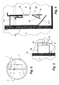
- FIG. 1 shows an example of a small wastewater treatment plant, intended for a decentralized use.
- the small sewage treatment plant has a container 1 with a feed pipe 2 in the container, a drain pipe 3 from the container 1 and a ventilation device 12.
- the container 1 is divided with a partition wall 13 into two chambers, wherein the chambers represent different treatment stages.
- the chamber 4 is used to carry out a mechanical pre-cleaning (primary treatment, sludge storage) and is therefore also to be considered as pre-clarification stage.
- the other chamber - the chamber 5 - is a biological treatment stage.
- the two treatment stages 4, 5 are connected to one another by means of an exemplarily illustrated passage 6 in the dividing wall 13, so that pre-clarified wastewater after the mechanical pre-cleaning, controlled by the hydraulic equilibrium, can run from the chamber 4 into the chamber 5.
- the passage 6 is an opening in the partition wall 13.
- a separating device 7 is installed, which is fastened in the illustrated embodiment with a holding device 16 on the partition wall 13 in a simple manner.
- the holding device 16 is designed as a hook, which over the upper end of the partition 13, as in FIG. 1 evident, attacks.
- a compressed air jack 9 or other conveyor device is installed as a clear water withdrawal pump.
- the separating device 7 is open in the lower region and has a correspondingly formed bevel 11 there. Furthermore, in an exemplary embodiment, one or more openings 10 are contained in the lower region of the separating device 7.
- Another compressed air lifter 8 or another conveyor device for pumping excess sludge from the biological stage 5 into the mechanical pre-cleaning 4 is preferably also at the separating device 7 attached.
- the resulting during operation of one or both conveyor oscillations are used to solve on the separator 7 or on the formed slope 11 sludge, so that this gravitationally back in the biological treatment stage 5 can get.
- the conveying devices 8, 9 are connected in a manner to the separating device 7, so that the vibrations arising during an operation thereof are transmitted to or induced in the separating device 7.
- the pre-clarified by the above processes wastewater passes from the mechanical pre-cleaning 4 through the opening 6 of the partition 13 in the biological treatment stage 5. There, the biological wastewater treatment takes place.
- the air required for the biological wastewater treatment process is supplied via an aerator 12 shown by way of example.
- the schematically illustrated aerator 12 is connected in a manner not shown to a compressor, is supplied to the ambient air for the purpose of ventilation in the biological treatment stage 5.
- biological treatment stage 5 is activated sludge, through which the pre-clarified wastewater is purified.
- the biological purified wastewater can leave the biological treatment stage 5 only by the separation device 7. In the separation device 7 there is a separation of the biologically purified wastewater from the activated sludge.
- one or more openings 10 are attached in a preferred embodiment in the lower region of the separator 7.
- the openings 10 can serve as an inflow and thus for establishing a hydraulic connection between the biological treatment stage 5 and the interior of the separating device 7.
- an influx mainly takes place through the openings 10, while the sedimented activated sludge sediments through the lower opening of the separator 7 and on the slope 7 out.
- the air lift 9 is arranged within the separator 7 such that its mouth-side opening is located in an upper portion of the separator.
- the compressed air lifter 9 conveys at predetermined intervals (for example, every 30 minutes) purified wastewater from the separator 7 in the sequence 3.
- the compressed air lifter 9 and the compressed air lifter 9 acting compressor is connected in a manner not shown to a control unit ,
- the separator 7 typically periodically in periods in which the wastewater in the separator 7 dwells without flow, so that in these periods, the separation of biologically purified wastewater and activated sludge without impairing flows can take place.
- the size of the separation device 7 and the time intervals between two clear water withdrawal processes in this case has a significant influence on the separation process between biologically purified wastewater and the activated sludge.
- the duration of the conveying process and the size of the separating device are matched to one another in such a way that only wastewater from the separating device is always challenged, which has already separated from the activated sludge in the period before the current conveying process. This avoids that during a current conveying process in the separation device 7 nachströmendes wastewater with activated sludge constituents can rise so far that the clear water withdrawal pump, which in the illustrated embodiment by the Air lifter 9 realized clear water is detected with contained activated sludge constituents.
- the compressed air lift 9 is installed in the separation device 7 in such a way that the amount of wastewater conveyed is limited to a lower water level 15, a problem-free separation process of biologically purified wastewater and activated sludge is provided.
- a problem-free separation process of biologically purified wastewater and activated sludge is provided.
- the container 1 via the supply line 2 flows in that increases in both chambers 4, 5, the water level, for example, to the level of the water level 14.
- the water level decreases
- the hydraulic connection to the pre-treatment 4 by means of the passage 6 simultaneously with the withdrawal of clear water from the separator 7 and the biological treatment 5 the same amount of pre-treated wastewater flows into the biological treatment stage. 5 one.
- the height-wise arrangement of the compressed air lift 9 in conjunction with the controller ensures that in a time interval in each case only a fixed amount is conveyed out of the separating device 7 out. This in turn ensures that the time required for the settling process is available. A hydraulic overload of the separator 7 is thus excluded.
- the additional placement of a float within the pre-treatment stage 4 can report a flood alarm or regulate ventilation times or control delivery periods of the compressed air lift 9.
- the container There is a container of 2 m diameter and a division into two chambers by a central partition, which divides the container into two equal halves. Connected to the container are four inhabitants with a daily waste water quantity of 150 l per inhabitant.
- the container has a water depth of 1.2 m.
- the surface area of each treatment step is approximately 1.5 m 2 .
- the average sewage inflow is 0.06 m 3 / h (the so-called Q 10 value).
- the separator has a length of 40 cm and a width of 30 cm and a height of 80 cm. This results in a volume of about 96 I in the separator.
- the clear water withdrawal pump is turned on for 30 minutes every 30 minutes in this example.
- the clear water withdrawal pump has a capacity of 30 l per minute.
- the upper portion of the separator is designed so that it protrudes, for example, 10 cm above the actual water level.
- the drain can prevent a corresponding sealing of the drain pipe, that here an overflow leads to the uncontrolled flow of wastewater with activated sludge.
- the process of biological wastewater treatment increases the activated sludge. This results in excess sludge, which is to promote in the field of mechanical pre-cleaning.
- This process is effected by the air lift 8.
- the air lift 8 is shown in the illustrated Embodiment attached to the separator 7.
- the distance 17 of the intake opening of the compressed air lift 8 causes at a correct distance 17 that each correct amount of excess sludge from the biological treatment stage is promoted out.
- the distance measure moves depending on the settling time for the mud between 10 and 50% of the water depth of the water level 15. Experiments have shown that especially the range between 20 and 30% of the water depth of the water level 15 is a preferred distance measure.
- the settled activated sludge amount which is within the distance measure 17 is the amount of activated sludge necessary for the correct operation of the biological stage 5.
- This amount of activated sludge within the distance 17 can not be promoted by the arrangement of the air lift 8 in the mechanical stage. Only the additionally occurring activated sludge, the so-called excess sludge, which goes beyond the distance 17, is conveyed by the compressed air lifter 8 in the mechanical stage. Due to this special feature, an always constant amount of activated sludge can be secured in the biological stage.
- the airlift 8 can also be used to cause a recirculation.
- the process of denitrification can be optimized.
- the oxidized in the biological stage ammonium can be denitrified under the ideal conditions (absence of atmospheric oxygen, sufficient carbon availability) in the mechanical precursor 4.
- the associated carbon degradation leads to a corresponding reduction in fan performance in the biological stage and to a corresponding Optimization of the pH value (nitrification reduces the pH value by releasing H + ions and the denitrification process can reverse this pH reduction).
- Another advantage of the arrangement is that on the compressed air lifter 8 in addition to the actual sludge production and purified or partially purified wastewater from the biological stage 5 is promoted in the mechanical precursor 4 and thus ensures that due to the hydraulic connection between the two stages 4, 5 carbonaceous wastewater enters the biological stage 5.
- the small wastewater treatment plant is only slightly loaded (under load operation)
- can be supplied by a corresponding recirculation the biological stage with carbon and other nutrients, so that the activated sludge remains active.
- this process ensures an equalization of load fluctuations.
- different delivery times and thus amounts of recirculation water, even for different loads can be set and realized.
- FIGS. 4 and 5 a separator 18 is shown according to another embodiment.
- the separator 18 is designed in principle as the separator 7 of the embodiment of FIGS. 1 to 3 ,
- the separation device 18 is also suspended in a biological treatment stage 5 of a small sewage treatment plant, by means of hooks, which separates the partition wall 13 between the two stages 4, 5.
- the separating device 18 is in FIG. 4 shown in a longitudinal section.
- the separating device 18 has above its slope 11.1 via a on the wall facing away from the partition wall 13 of the container 1 wall 21 inside guide element 19.
- the guide element 19 is inclined inwards in the direction of the slope 11.1.
- the baffle 19 thus forms with the inside of the aforementioned wall 21 of the separator 18 is a downwardly open receptacle 20.
- the receptacle 20 has in its upper end portion within the wall 21 of the separator 18 via one or more openings 22.
- the thus formed Receptacle 20 serves as an air bubble trap, specifically for receiving air bubbles which are introduced into the biological treatment stage 5 through the ventilation 12.1, when they enter through the lower-side opening of the separator 18 in this. These bubbles are trapped due to their tendency to rise. Background of the catching of above the slope 11.1 entering air bubbles within the receptacle 20 is that they do not enter the actual separation device 18, whereby the separation process between activated sludge and purified wastewater would be affected. Is exploited in this principle that the slope 11.1 prevents the ingress of air bubbles that rise vertically below the slope 11.1. This applies in principle also for the areas left open by the slope 11.1. However, it can not be completely prevented that air bubbles occur occasionally as a result of the opening adjoining the wall 21 on the underside of an operation of the ventilation 12.
- the guide element 19 is thus a built-in element which traps air bubbles entering in the manner of a chicane. These enter from the introduced into the wall 21 openings 22 again in the biological stage 5 a.
- the receptacle 20 as an air bubble trap is described above by way of example. For a person skilled in the art, numerous other embodiments result in the same effect, without these having to be described in more detail.
- the openings 10 and 10.1 can, if there is a risk that enter through these unwanted air bubbles in the interior of the respective separation device 7 and 18, also with an air bubble trap, as described in principle above, be equipped.
- the pumps used in the described embodiments can be kept height adjustable. Such height adjustment can be done depending on the liquid level within the respective separation device and thus within the biological treatment stage.
- the opening 6 can also be closed, so that the feeding of the biological treatment stage from the mechanical cleaning via a conveyor, preferably a compressed air lift takes place.
- the container can also be divided by partitions in three or four equal or different sized chambers.
- two or more containers, each with or without a partition represent different treatment levels.
- the different design can be used with the underlying method and the device in the existing distribution.
- a partition penetrating the opening may be present between the Vorschreibhave and the biological treatment stage in the upper part of the partition an open connection through which automatically pre-clarified wastewater from the Vor gleichhave when pumping clear water into the biological treatment stage.
- the separation device can also be provided as a chamber within the container, so that then no separate housing for the separation device must be made.
- the method described here and the devices described are also suitable for retrofitting existing containers, since the existing containers usually have corresponding openings in the partitions, which must be laboriously closed and sealed when retrofitted with conventional SBR systems.
- Another advantage of the short time intervals between two pumping operations of the clear water outlet is that only small amounts of water have to be stored in the system (just for the period between two pumping processes, ie, for example, for 30 minutes).
- valuable container volume for wastewater treatment can be used instead of being used for the storage of wastewater, as is the case with conventional SBR systems where the clear water withdrawal occurs only every six or every eight or every 12 hours or any other long period of time takes place.
Landscapes
- Life Sciences & Earth Sciences (AREA)
- Engineering & Computer Science (AREA)
- Water Supply & Treatment (AREA)
- Hydrology & Water Resources (AREA)
- Environmental & Geological Engineering (AREA)
- Chemical & Material Sciences (AREA)
- Organic Chemistry (AREA)
- Microbiology (AREA)
- Biodiversity & Conservation Biology (AREA)
- Health & Medical Sciences (AREA)
- Molecular Biology (AREA)
- Mechanical Engineering (AREA)
- Biological Treatment Of Waste Water (AREA)
- Activated Sludge Processes (AREA)
Applications Claiming Priority (1)
| Application Number | Priority Date | Filing Date | Title |
|---|---|---|---|
| DE102009032763A DE102009032763A1 (de) | 2009-07-11 | 2009-07-11 | Verfahren und Vorrichtung zur Reinigung von Abwasser |
Publications (3)
| Publication Number | Publication Date |
|---|---|
| EP2284128A2 true EP2284128A2 (fr) | 2011-02-16 |
| EP2284128A3 EP2284128A3 (fr) | 2012-03-28 |
| EP2284128B1 EP2284128B1 (fr) | 2014-10-15 |
Family
ID=43066653
Family Applications (1)
| Application Number | Title | Priority Date | Filing Date |
|---|---|---|---|
| EP20100168800 Not-in-force EP2284128B1 (fr) | 2009-07-11 | 2010-07-08 | Procédé et dispositif de nettoyage d'eaux usées et dispositif de séparation correspondant |
Country Status (2)
| Country | Link |
|---|---|
| EP (1) | EP2284128B1 (fr) |
| DE (1) | DE102009032763A1 (fr) |
Cited By (3)
| Publication number | Priority date | Publication date | Assignee | Title |
|---|---|---|---|---|
| CN102328993A (zh) * | 2011-08-26 | 2012-01-25 | 山东水务环保科技发展有限公司 | 小型污水处理系统 |
| CN106277319A (zh) * | 2016-08-30 | 2017-01-04 | 青岛思普润水处理股份有限公司 | 一种基于MBBR的Bardenpho脱氮除磷工艺 |
| CN118063051A (zh) * | 2024-04-19 | 2024-05-24 | 深圳捷工医疗装备股份有限公司 | 一种医疗污水消毒净化设备 |
Families Citing this family (1)
| Publication number | Priority date | Publication date | Assignee | Title |
|---|---|---|---|---|
| CN107178678B (zh) * | 2017-06-05 | 2019-04-26 | 浙江水利水电学院 | 一种防堵塞的导流管件及其安装方法 |
Family Cites Families (11)
| Publication number | Priority date | Publication date | Assignee | Title |
|---|---|---|---|---|
| DE19538387A1 (de) * | 1995-10-14 | 1997-04-24 | Theodor Zink Gmbh | Verfahren und Vorrichtung zur Umrüstung einer Mehrkammer-Kleinkläranlage |
| EP0893413B1 (fr) * | 1997-07-17 | 2004-01-21 | J.H. & Wilhelm Finger GmbH & Co. KG | Procédé et dispositif pour le traitement biologique de liquides, en particulier pour la complète clarification de l'eau usée |
| US6190554B1 (en) * | 1998-03-04 | 2001-02-20 | Mikkel G. Mandt | Surge anoxic mix sequencing batch reactor systems |
| EP1428800A1 (fr) * | 2002-12-12 | 2004-06-16 | Reinhard Boller | Procédé et dispositif pour le contrôle et la régulation d' un procédé de traítement d'eau résiduaire |
| DE20302765U1 (de) * | 2003-02-19 | 2003-05-15 | Wißmann, Frank, 32457 Porta Westfalica | Kleinkläranlage |
| DE202004001854U1 (de) * | 2004-02-06 | 2004-07-15 | Wissmann Elektronik Gmbh | Kleinkläranlage |
| DE102006024717B4 (de) * | 2006-05-26 | 2018-02-08 | Klaro Gmbh | Verfahren zum Betrieb eines Drucklufthebersystems für eine Kleinkläranlage und Drucklufthebersystem |
| DE202007000048U1 (de) * | 2007-11-22 | 2008-01-17 | Solid-Clair Watersystems Gmbh & Co. Kg | Kompakte Heberanordnung |
| DE102007058177A1 (de) * | 2007-12-02 | 2009-06-04 | Reinhard Boller | Verfahren und Vorrichtung zur Optimierung einer Kleinkläranlagen oder kleinen Kläranlage durch Vermeidung oder Verminderung des Austrages von Schlammpartikeln |
| DE202007016942U1 (de) * | 2007-12-03 | 2008-02-21 | Mall Gmbh | Kläranlage |
| DE202008009513U1 (de) * | 2008-07-14 | 2008-09-11 | PRÄDEL, Birgit | Vorrichtung in Form eines Festbettkörpers |
-
2009
- 2009-07-11 DE DE102009032763A patent/DE102009032763A1/de not_active Withdrawn
-
2010
- 2010-07-08 EP EP20100168800 patent/EP2284128B1/fr not_active Not-in-force
Non-Patent Citations (1)
| Title |
|---|
| None |
Cited By (4)
| Publication number | Priority date | Publication date | Assignee | Title |
|---|---|---|---|---|
| CN102328993A (zh) * | 2011-08-26 | 2012-01-25 | 山东水务环保科技发展有限公司 | 小型污水处理系统 |
| CN106277319A (zh) * | 2016-08-30 | 2017-01-04 | 青岛思普润水处理股份有限公司 | 一种基于MBBR的Bardenpho脱氮除磷工艺 |
| CN106277319B (zh) * | 2016-08-30 | 2019-06-28 | 青岛思普润水处理股份有限公司 | 一种基于MBBR的Bardenpho脱氮除磷工艺 |
| CN118063051A (zh) * | 2024-04-19 | 2024-05-24 | 深圳捷工医疗装备股份有限公司 | 一种医疗污水消毒净化设备 |
Also Published As
| Publication number | Publication date |
|---|---|
| EP2284128A3 (fr) | 2012-03-28 |
| EP2284128B1 (fr) | 2014-10-15 |
| DE102009032763A1 (de) | 2011-01-13 |
Similar Documents
| Publication | Publication Date | Title |
|---|---|---|
| DE102007035910B4 (de) | Verfahren und Vorrichtung zur Rückgewinnung von Magnesiumammoniumphosphat bei der Klärschlammbehandlung | |
| DE1784338A1 (de) | Schlamm-Klaeranlage | |
| DE102007058177A1 (de) | Verfahren und Vorrichtung zur Optimierung einer Kleinkläranlagen oder kleinen Kläranlage durch Vermeidung oder Verminderung des Austrages von Schlammpartikeln | |
| DE102014015488B4 (de) | Zweifunktionaler Druckluftheber für biologische Kläranlagen, Verfahren zu dessen Betrieb und dessen Verwendung | |
| DE102008020938A1 (de) | Verfahren und Vorrichtung zur Optimierung einer Kleinkläranlagen oder kleinen Kläranlage durch Vermeidung oder Verminderung des Austrages von Schlammpartikeln | |
| AT393116B (de) | Verfahren und anlage zum reinigen von abwasser | |
| DE60218657T2 (de) | Vorrichtung und verfahren zur trennung von suspensionen, insbesondere bei abwasserreinigung | |
| EP2284128B1 (fr) | Procédé et dispositif de nettoyage d'eaux usées et dispositif de séparation correspondant | |
| AT515878B1 (de) | Verfahren zur Abwasserklärung | |
| DE202012004597U1 (de) | Kläranlage mit Siphonüberlauf | |
| DE1658101C3 (de) | Vorrichtung zum Reinigen von organische Abfallstoffe enthaltendem Abwasser | |
| EP3740455B1 (fr) | Procédé de récupération de phosphate d'ammonium de magnésium | |
| DE60100345T2 (de) | Abwasserbehandlungssystem | |
| EP0968965A1 (fr) | Système et procédé discontinu pour traitement biologique des eaux usées | |
| EP1031540B1 (fr) | Appareil de traitement de l'eau | |
| DE4307288A1 (de) | Verfahren zur biologischen Abwasserreinigung mit integrierter Pufferung | |
| EP1559686B1 (fr) | Clarificateur avec un dispositif de sortie pour l'eau clarifiée | |
| DE102009039316A1 (de) | Abwasserreinigungsanlage und Verfahren zur Abwasserreinigung | |
| DE2741142A1 (de) | Biologische hausklaeranlage | |
| DE202009017869U1 (de) | Vorrichtung zum Trennen von gasförmigen, flüssigen und festen Stoffen in einem Bioreaktor | |
| DE10123152B4 (de) | Biologische Kläranlage für kommunale, gewerbliche und landwirtschaftliche Abwässer und Verfahren zum Betreiben der Anlage | |
| EP2826753A1 (fr) | Petite station d'épuration des eaux usées | |
| DE19951194A1 (de) | Mehrzweckschacht, Kleinkläranlage und Abwasserbehandlungsverfahren | |
| EP2865652B1 (fr) | Procédé et appareil d'optimisation d'une petite station d'épuration par élimination ou réduction du rejet de particules de boue provenant du dispositif de levage pneumatique pour l'évacuation des eaux clarifiées | |
| EP1434740B1 (fr) | Dispositif de traitement biologique des eaux usees |
Legal Events
| Date | Code | Title | Description |
|---|---|---|---|
| PUAI | Public reference made under article 153(3) epc to a published international application that has entered the european phase |
Free format text: ORIGINAL CODE: 0009012 |
|
| AK | Designated contracting states |
Kind code of ref document: A2 Designated state(s): AL AT BE BG CH CY CZ DE DK EE ES FI FR GB GR HR HU IE IS IT LI LT LU LV MC MK MT NL NO PL PT RO SE SI SK SM TR |
|
| AX | Request for extension of the european patent |
Extension state: BA ME RS |
|
| PUAL | Search report despatched |
Free format text: ORIGINAL CODE: 0009013 |
|
| AK | Designated contracting states |
Kind code of ref document: A3 Designated state(s): AL AT BE BG CH CY CZ DE DK EE ES FI FR GB GR HR HU IE IS IT LI LT LU LV MC MK MT NL NO PL PT RO SE SI SK SM TR |
|
| AX | Request for extension of the european patent |
Extension state: BA ME RS |
|
| RIC1 | Information provided on ipc code assigned before grant |
Ipc: C02F 3/12 20060101AFI20120223BHEP Ipc: C02F 1/34 20060101ALI20120223BHEP Ipc: C02F 3/22 20060101ALI20120223BHEP Ipc: C02F 1/00 20060101ALI20120223BHEP Ipc: C02F 3/00 20060101ALI20120223BHEP Ipc: C02F 9/00 20060101ALI20120223BHEP |
|
| 17P | Request for examination filed |
Effective date: 20120330 |
|
| 17Q | First examination report despatched |
Effective date: 20120530 |
|
| GRAP | Despatch of communication of intention to grant a patent |
Free format text: ORIGINAL CODE: EPIDOSNIGR1 |
|
| INTG | Intention to grant announced |
Effective date: 20131206 |
|
| GRAP | Despatch of communication of intention to grant a patent |
Free format text: ORIGINAL CODE: EPIDOSNIGR1 |
|
| INTG | Intention to grant announced |
Effective date: 20140505 |
|
| GRAS | Grant fee paid |
Free format text: ORIGINAL CODE: EPIDOSNIGR3 |
|
| GRAA | (expected) grant |
Free format text: ORIGINAL CODE: 0009210 |
|
| AK | Designated contracting states |
Kind code of ref document: B1 Designated state(s): AL AT BE BG CH CY CZ DE DK EE ES FI FR GB GR HR HU IE IS IT LI LT LU LV MC MK MT NL NO PL PT RO SE SI SK SM TR |
|
| RAP1 | Party data changed (applicant data changed or rights of an application transferred) |
Owner name: BOLLER, REINHARD |
|
| REG | Reference to a national code |
Ref country code: GB Ref legal event code: FG4D Free format text: NOT ENGLISH Ref country code: CH Ref legal event code: EP |
|
| RIN1 | Information on inventor provided before grant (corrected) |
Inventor name: BOLLER, REINHARD |
|
| REG | Reference to a national code |
Ref country code: IE Ref legal event code: FG4D Free format text: LANGUAGE OF EP DOCUMENT: GERMAN |
|
| REG | Reference to a national code |
Ref country code: AT Ref legal event code: REF Ref document number: 691566 Country of ref document: AT Kind code of ref document: T Effective date: 20141115 |
|
| REG | Reference to a national code |
Ref country code: DE Ref legal event code: R096 Ref document number: 502010008061 Country of ref document: DE Effective date: 20141127 |
|
| REG | Reference to a national code |
Ref country code: NL Ref legal event code: VDEP Effective date: 20141015 |
|
| REG | Reference to a national code |
Ref country code: LT Ref legal event code: MG4D |
|
| PG25 | Lapsed in a contracting state [announced via postgrant information from national office to epo] |
Ref country code: NL Free format text: LAPSE BECAUSE OF FAILURE TO SUBMIT A TRANSLATION OF THE DESCRIPTION OR TO PAY THE FEE WITHIN THE PRESCRIBED TIME-LIMIT Effective date: 20141015 |
|
| PG25 | Lapsed in a contracting state [announced via postgrant information from national office to epo] |
Ref country code: LT Free format text: LAPSE BECAUSE OF FAILURE TO SUBMIT A TRANSLATION OF THE DESCRIPTION OR TO PAY THE FEE WITHIN THE PRESCRIBED TIME-LIMIT Effective date: 20141015 Ref country code: IS Free format text: LAPSE BECAUSE OF FAILURE TO SUBMIT A TRANSLATION OF THE DESCRIPTION OR TO PAY THE FEE WITHIN THE PRESCRIBED TIME-LIMIT Effective date: 20150215 Ref country code: NO Free format text: LAPSE BECAUSE OF FAILURE TO SUBMIT A TRANSLATION OF THE DESCRIPTION OR TO PAY THE FEE WITHIN THE PRESCRIBED TIME-LIMIT Effective date: 20150115 Ref country code: PT Free format text: LAPSE BECAUSE OF FAILURE TO SUBMIT A TRANSLATION OF THE DESCRIPTION OR TO PAY THE FEE WITHIN THE PRESCRIBED TIME-LIMIT Effective date: 20150216 Ref country code: FI Free format text: LAPSE BECAUSE OF FAILURE TO SUBMIT A TRANSLATION OF THE DESCRIPTION OR TO PAY THE FEE WITHIN THE PRESCRIBED TIME-LIMIT Effective date: 20141015 Ref country code: ES Free format text: LAPSE BECAUSE OF FAILURE TO SUBMIT A TRANSLATION OF THE DESCRIPTION OR TO PAY THE FEE WITHIN THE PRESCRIBED TIME-LIMIT Effective date: 20141015 |
|
| PG25 | Lapsed in a contracting state [announced via postgrant information from national office to epo] |
Ref country code: SE Free format text: LAPSE BECAUSE OF FAILURE TO SUBMIT A TRANSLATION OF THE DESCRIPTION OR TO PAY THE FEE WITHIN THE PRESCRIBED TIME-LIMIT Effective date: 20141015 Ref country code: HR Free format text: LAPSE BECAUSE OF FAILURE TO SUBMIT A TRANSLATION OF THE DESCRIPTION OR TO PAY THE FEE WITHIN THE PRESCRIBED TIME-LIMIT Effective date: 20141015 Ref country code: GR Free format text: LAPSE BECAUSE OF FAILURE TO SUBMIT A TRANSLATION OF THE DESCRIPTION OR TO PAY THE FEE WITHIN THE PRESCRIBED TIME-LIMIT Effective date: 20150116 Ref country code: PL Free format text: LAPSE BECAUSE OF FAILURE TO SUBMIT A TRANSLATION OF THE DESCRIPTION OR TO PAY THE FEE WITHIN THE PRESCRIBED TIME-LIMIT Effective date: 20141015 Ref country code: LV Free format text: LAPSE BECAUSE OF FAILURE TO SUBMIT A TRANSLATION OF THE DESCRIPTION OR TO PAY THE FEE WITHIN THE PRESCRIBED TIME-LIMIT Effective date: 20141015 Ref country code: CY Free format text: LAPSE BECAUSE OF FAILURE TO SUBMIT A TRANSLATION OF THE DESCRIPTION OR TO PAY THE FEE WITHIN THE PRESCRIBED TIME-LIMIT Effective date: 20141015 |
|
| REG | Reference to a national code |
Ref country code: DE Ref legal event code: R097 Ref document number: 502010008061 Country of ref document: DE |
|
| PG25 | Lapsed in a contracting state [announced via postgrant information from national office to epo] |
Ref country code: DK Free format text: LAPSE BECAUSE OF FAILURE TO SUBMIT A TRANSLATION OF THE DESCRIPTION OR TO PAY THE FEE WITHIN THE PRESCRIBED TIME-LIMIT Effective date: 20141015 Ref country code: CZ Free format text: LAPSE BECAUSE OF FAILURE TO SUBMIT A TRANSLATION OF THE DESCRIPTION OR TO PAY THE FEE WITHIN THE PRESCRIBED TIME-LIMIT Effective date: 20141015 Ref country code: RO Free format text: LAPSE BECAUSE OF FAILURE TO SUBMIT A TRANSLATION OF THE DESCRIPTION OR TO PAY THE FEE WITHIN THE PRESCRIBED TIME-LIMIT Effective date: 20141015 Ref country code: SK Free format text: LAPSE BECAUSE OF FAILURE TO SUBMIT A TRANSLATION OF THE DESCRIPTION OR TO PAY THE FEE WITHIN THE PRESCRIBED TIME-LIMIT Effective date: 20141015 Ref country code: EE Free format text: LAPSE BECAUSE OF FAILURE TO SUBMIT A TRANSLATION OF THE DESCRIPTION OR TO PAY THE FEE WITHIN THE PRESCRIBED TIME-LIMIT Effective date: 20141015 |
|
| PLBE | No opposition filed within time limit |
Free format text: ORIGINAL CODE: 0009261 |
|
| STAA | Information on the status of an ep patent application or granted ep patent |
Free format text: STATUS: NO OPPOSITION FILED WITHIN TIME LIMIT |
|
| PG25 | Lapsed in a contracting state [announced via postgrant information from national office to epo] |
Ref country code: IT Free format text: LAPSE BECAUSE OF FAILURE TO SUBMIT A TRANSLATION OF THE DESCRIPTION OR TO PAY THE FEE WITHIN THE PRESCRIBED TIME-LIMIT Effective date: 20141015 |
|
| 26N | No opposition filed |
Effective date: 20150716 |
|
| PG25 | Lapsed in a contracting state [announced via postgrant information from national office to epo] |
Ref country code: SI Free format text: LAPSE BECAUSE OF FAILURE TO SUBMIT A TRANSLATION OF THE DESCRIPTION OR TO PAY THE FEE WITHIN THE PRESCRIBED TIME-LIMIT Effective date: 20141015 Ref country code: MC Free format text: LAPSE BECAUSE OF FAILURE TO SUBMIT A TRANSLATION OF THE DESCRIPTION OR TO PAY THE FEE WITHIN THE PRESCRIBED TIME-LIMIT Effective date: 20141015 |
|
| REG | Reference to a national code |
Ref country code: CH Ref legal event code: PL |
|
| GBPC | Gb: european patent ceased through non-payment of renewal fee |
Effective date: 20150708 |
|
| PG25 | Lapsed in a contracting state [announced via postgrant information from national office to epo] |
Ref country code: LU Free format text: LAPSE BECAUSE OF FAILURE TO SUBMIT A TRANSLATION OF THE DESCRIPTION OR TO PAY THE FEE WITHIN THE PRESCRIBED TIME-LIMIT Effective date: 20150708 |
|
| REG | Reference to a national code |
Ref country code: IE Ref legal event code: MM4A |
|
| PG25 | Lapsed in a contracting state [announced via postgrant information from national office to epo] |
Ref country code: CH Free format text: LAPSE BECAUSE OF NON-PAYMENT OF DUE FEES Effective date: 20150731 Ref country code: LI Free format text: LAPSE BECAUSE OF NON-PAYMENT OF DUE FEES Effective date: 20150731 Ref country code: GB Free format text: LAPSE BECAUSE OF NON-PAYMENT OF DUE FEES Effective date: 20150708 |
|
| REG | Reference to a national code |
Ref country code: FR Ref legal event code: ST Effective date: 20160331 |
|
| PG25 | Lapsed in a contracting state [announced via postgrant information from national office to epo] |
Ref country code: FR Free format text: LAPSE BECAUSE OF NON-PAYMENT OF DUE FEES Effective date: 20150731 |
|
| PG25 | Lapsed in a contracting state [announced via postgrant information from national office to epo] |
Ref country code: IE Free format text: LAPSE BECAUSE OF NON-PAYMENT OF DUE FEES Effective date: 20150708 |
|
| REG | Reference to a national code |
Ref country code: AT Ref legal event code: MM01 Ref document number: 691566 Country of ref document: AT Kind code of ref document: T Effective date: 20150708 |
|
| PG25 | Lapsed in a contracting state [announced via postgrant information from national office to epo] |
Ref country code: AT Free format text: LAPSE BECAUSE OF NON-PAYMENT OF DUE FEES Effective date: 20150708 |
|
| PG25 | Lapsed in a contracting state [announced via postgrant information from national office to epo] |
Ref country code: MT Free format text: LAPSE BECAUSE OF FAILURE TO SUBMIT A TRANSLATION OF THE DESCRIPTION OR TO PAY THE FEE WITHIN THE PRESCRIBED TIME-LIMIT Effective date: 20141015 |
|
| PG25 | Lapsed in a contracting state [announced via postgrant information from national office to epo] |
Ref country code: BG Free format text: LAPSE BECAUSE OF FAILURE TO SUBMIT A TRANSLATION OF THE DESCRIPTION OR TO PAY THE FEE WITHIN THE PRESCRIBED TIME-LIMIT Effective date: 20141015 Ref country code: SM Free format text: LAPSE BECAUSE OF FAILURE TO SUBMIT A TRANSLATION OF THE DESCRIPTION OR TO PAY THE FEE WITHIN THE PRESCRIBED TIME-LIMIT Effective date: 20141015 Ref country code: HU Free format text: LAPSE BECAUSE OF FAILURE TO SUBMIT A TRANSLATION OF THE DESCRIPTION OR TO PAY THE FEE WITHIN THE PRESCRIBED TIME-LIMIT; INVALID AB INITIO Effective date: 20100708 |
|
| PG25 | Lapsed in a contracting state [announced via postgrant information from national office to epo] |
Ref country code: BE Free format text: LAPSE BECAUSE OF NON-PAYMENT OF DUE FEES Effective date: 20150731 |
|
| PG25 | Lapsed in a contracting state [announced via postgrant information from national office to epo] |
Ref country code: TR Free format text: LAPSE BECAUSE OF FAILURE TO SUBMIT A TRANSLATION OF THE DESCRIPTION OR TO PAY THE FEE WITHIN THE PRESCRIBED TIME-LIMIT Effective date: 20141015 |
|
| PG25 | Lapsed in a contracting state [announced via postgrant information from national office to epo] |
Ref country code: MK Free format text: LAPSE BECAUSE OF FAILURE TO SUBMIT A TRANSLATION OF THE DESCRIPTION OR TO PAY THE FEE WITHIN THE PRESCRIBED TIME-LIMIT Effective date: 20141015 |
|
| PG25 | Lapsed in a contracting state [announced via postgrant information from national office to epo] |
Ref country code: AL Free format text: LAPSE BECAUSE OF FAILURE TO SUBMIT A TRANSLATION OF THE DESCRIPTION OR TO PAY THE FEE WITHIN THE PRESCRIBED TIME-LIMIT Effective date: 20141015 |
|
| PGFP | Annual fee paid to national office [announced via postgrant information from national office to epo] |
Ref country code: DE Payment date: 20200731 Year of fee payment: 11 |
|
| REG | Reference to a national code |
Ref country code: DE Ref legal event code: R082 Ref document number: 502010008061 Country of ref document: DE Representative=s name: HAVERKAMP PATENTANWAELTE PARTG MBB, DE |
|
| REG | Reference to a national code |
Ref country code: DE Ref legal event code: R119 Ref document number: 502010008061 Country of ref document: DE |
|
| PG25 | Lapsed in a contracting state [announced via postgrant information from national office to epo] |
Ref country code: DE Free format text: LAPSE BECAUSE OF NON-PAYMENT OF DUE FEES Effective date: 20220201 |