EP2284128A2 - Method and device for cleaning waste water and separation device for same - Google Patents
Method and device for cleaning waste water and separation device for same Download PDFInfo
- Publication number
- EP2284128A2 EP2284128A2 EP20100168800 EP10168800A EP2284128A2 EP 2284128 A2 EP2284128 A2 EP 2284128A2 EP 20100168800 EP20100168800 EP 20100168800 EP 10168800 A EP10168800 A EP 10168800A EP 2284128 A2 EP2284128 A2 EP 2284128A2
- Authority
- EP
- European Patent Office
- Prior art keywords
- separating device
- wastewater
- clear water
- conveying
- biological
- Prior art date
- Legal status (The legal status is an assumption and is not a legal conclusion. Google has not performed a legal analysis and makes no representation as to the accuracy of the status listed.)
- Granted
Links
Images

Classifications
-
- C—CHEMISTRY; METALLURGY
- C02—TREATMENT OF WATER, WASTE WATER, SEWAGE, OR SLUDGE
- C02F—TREATMENT OF WATER, WASTE WATER, SEWAGE, OR SLUDGE
- C02F3/00—Biological treatment of water, waste water, or sewage
- C02F3/02—Aerobic processes
- C02F3/12—Activated sludge processes
- C02F3/1236—Particular type of activated sludge installations
- C02F3/1242—Small compact installations for use in homes, apartment blocks, hotels or the like
-
- C—CHEMISTRY; METALLURGY
- C02—TREATMENT OF WATER, WASTE WATER, SEWAGE, OR SLUDGE
- C02F—TREATMENT OF WATER, WASTE WATER, SEWAGE, OR SLUDGE
- C02F1/00—Treatment of water, waste water, or sewage
- C02F1/34—Treatment of water, waste water, or sewage with mechanical oscillations
-
- C—CHEMISTRY; METALLURGY
- C02—TREATMENT OF WATER, WASTE WATER, SEWAGE, OR SLUDGE
- C02F—TREATMENT OF WATER, WASTE WATER, SEWAGE, OR SLUDGE
- C02F3/00—Biological treatment of water, waste water, or sewage
- C02F3/006—Regulation methods for biological treatment
-
- C—CHEMISTRY; METALLURGY
- C02—TREATMENT OF WATER, WASTE WATER, SEWAGE, OR SLUDGE
- C02F—TREATMENT OF WATER, WASTE WATER, SEWAGE, OR SLUDGE
- C02F3/00—Biological treatment of water, waste water, or sewage
- C02F3/02—Aerobic processes
- C02F3/12—Activated sludge processes
- C02F3/1205—Particular type of activated sludge processes
- C02F3/121—Multistep treatment
-
- C—CHEMISTRY; METALLURGY
- C02—TREATMENT OF WATER, WASTE WATER, SEWAGE, OR SLUDGE
- C02F—TREATMENT OF WATER, WASTE WATER, SEWAGE, OR SLUDGE
- C02F3/00—Biological treatment of water, waste water, or sewage
- C02F3/02—Aerobic processes
- C02F3/12—Activated sludge processes
- C02F3/1236—Particular type of activated sludge installations
- C02F3/1242—Small compact installations for use in homes, apartment blocks, hotels or the like
- C02F3/1247—Small compact installations for use in homes, apartment blocks, hotels or the like comprising circular tanks with elements, e.g. decanters, aeration basins, in the form of segments, crowns or sectors
-
- C—CHEMISTRY; METALLURGY
- C02—TREATMENT OF WATER, WASTE WATER, SEWAGE, OR SLUDGE
- C02F—TREATMENT OF WATER, WASTE WATER, SEWAGE, OR SLUDGE
- C02F3/00—Biological treatment of water, waste water, or sewage
- C02F3/02—Aerobic processes
- C02F3/12—Activated sludge processes
- C02F3/1236—Particular type of activated sludge installations
- C02F3/1263—Sequencing batch reactors [SBR]
-
- C—CHEMISTRY; METALLURGY
- C02—TREATMENT OF WATER, WASTE WATER, SEWAGE, OR SLUDGE
- C02F—TREATMENT OF WATER, WASTE WATER, SEWAGE, OR SLUDGE
- C02F3/00—Biological treatment of water, waste water, or sewage
- C02F3/02—Aerobic processes
- C02F3/12—Activated sludge processes
- C02F3/22—Activated sludge processes using circulation pipes
- C02F3/223—Activated sludge processes using circulation pipes using "air-lift"
-
- C—CHEMISTRY; METALLURGY
- C02—TREATMENT OF WATER, WASTE WATER, SEWAGE, OR SLUDGE
- C02F—TREATMENT OF WATER, WASTE WATER, SEWAGE, OR SLUDGE
- C02F9/00—Multistage treatment of water, waste water or sewage
-
- C—CHEMISTRY; METALLURGY
- C02—TREATMENT OF WATER, WASTE WATER, SEWAGE, OR SLUDGE
- C02F—TREATMENT OF WATER, WASTE WATER, SEWAGE, OR SLUDGE
- C02F2203/00—Apparatus and plants for the biological treatment of water, waste water or sewage
-
- Y—GENERAL TAGGING OF NEW TECHNOLOGICAL DEVELOPMENTS; GENERAL TAGGING OF CROSS-SECTIONAL TECHNOLOGIES SPANNING OVER SEVERAL SECTIONS OF THE IPC; TECHNICAL SUBJECTS COVERED BY FORMER USPC CROSS-REFERENCE ART COLLECTIONS [XRACs] AND DIGESTS
- Y02—TECHNOLOGIES OR APPLICATIONS FOR MITIGATION OR ADAPTATION AGAINST CLIMATE CHANGE
- Y02A—TECHNOLOGIES FOR ADAPTATION TO CLIMATE CHANGE
- Y02A20/00—Water conservation; Efficient water supply; Efficient water use
- Y02A20/20—Controlling water pollution; Waste water treatment
- Y02A20/208—Off-grid powered water treatment
-
- Y—GENERAL TAGGING OF NEW TECHNOLOGICAL DEVELOPMENTS; GENERAL TAGGING OF CROSS-SECTIONAL TECHNOLOGIES SPANNING OVER SEVERAL SECTIONS OF THE IPC; TECHNICAL SUBJECTS COVERED BY FORMER USPC CROSS-REFERENCE ART COLLECTIONS [XRACs] AND DIGESTS
- Y02—TECHNOLOGIES OR APPLICATIONS FOR MITIGATION OR ADAPTATION AGAINST CLIMATE CHANGE
- Y02W—CLIMATE CHANGE MITIGATION TECHNOLOGIES RELATED TO WASTEWATER TREATMENT OR WASTE MANAGEMENT
- Y02W10/00—Technologies for wastewater treatment
- Y02W10/10—Biological treatment of water, waste water, or sewage
Definitions
- the invention relates to a method for the purification of wastewater by means of a small sewage treatment plant, in particular provided for a decentralized use septic system, with an inlet, a pre-treatment, a biological treatment stage and the biological treatment stage associated separation device with a clear water, which method in principle by a continuous process is carried out. Furthermore, the invention relates to a small wastewater treatment plant, especially for a decentralized use intended small wastewater treatment plant, with an inlet, a pre-treatment, a biological treatment stage and the biological treatment stage associated separation device with a clear water outlet. Furthermore, the invention relates to a separation device for such a small wastewater treatment plant.
- Small wastewater treatment plants or small wastewater treatment plants are used for decentralized wastewater disposal in rural areas where, for economic or other reasons, there is no sewer connection or production and therefore centralized wastewater treatment can not take place.
- Small wastewater treatment plants are designed in different ways technically differentiated.
- As a small wastewater treatment plants inter alia, wetland plants, trickling filter plants, fixed bed plants, fluidized bed plants, membrane plants and SBR plants are known. Widely used are the meantime, the so-called SBR systems (S equencing- B atch- R eactor or s equenzielles b iyogettia)).
- the SBR process also known as damming, treats wastewater "in portions".
- a chamber takes over the mechanical pre-treatment. There, the dirt particles settle as mud. Thereafter, the wastewater is transported at certain intervals in the biological treatment area (in said SBR reactor) and cleaned there. There is no direct connection between the mechanical treatment stage and the biological treatment stage.
- the separation between purified Wastewater and activated sludge take place in the same treatment stage only by a temporal separation of the processes.
- a disadvantage is considered in working after the SBR process wastewater treatment plants that the different water levels in the individual treatment stages require a corresponding tightness of the partitions.
- it is disadvantageous that, when retrofitting existing containers, existing passages in the partition walls must be lavishly sealed and sealed.
- conveyors are necessary to promote the wastewater from the mechanical treatment stage in the biological treatment stage.
- a correspondingly large buffer is required in order to be able to store the wastewater accordingly.
- An alternative to purification processes according to the SBR principle is the so-called CBR process known in the marketplace ( C ontinuous B atch R eactor or continuous biological purification), in which, in contrast to the SBR process, the mechanical pre-cleaning and the biological Treatment stage are connected to each other via an opening so that wastewater from the mechanical treatment stage can flow directly into the biological treatment stage.
- a suspended in the biological treatment stage separator separator
- Attached to the separation device is an outlet throttle which limits the outflow from the sewage treatment plant.
- the flow through the inlet is controlled. As a result, if more sewage of the sewage treatment plant flows, as can drain through the outlet throttle, the container or the individual treatment stages are stowed. The overflow is gradually reduced by the outflow from the throttle.
- a disadvantage of this method is that in the separator at the same time take place the settling of the sludge (downward movements) and that an influx of rising to the throttle wastewater (upward movement) take place. Only with a corresponding difference in the downward velocity of the sludge to the upward movement of the wastewater can be prevented that sludge components come into the process. In this case, this separation process only works if the downward velocity of the sludge is greater than the upward movement of the wastewater. But since it is known that the Absetz manufactureen a sludge can vary quite well, this can lead to mud loss due to lack of speed differences. Another disadvantage is that the throttle device can clog and thus larger amounts of wastewater can flow through the emergency overflow.
- the air lift for the excess sludge vent is coupled to the air duct for ventilation.
- excess sludge from the biological stage is conveyed to the mechanical stage at each aeration. This is a permanent deduction of activated sludge in the mechanical stage.
- excess sludge only arises as a function of the respective load, a continuous withdrawal during the aeration phase is not suitable for ensuring a constant or sufficient amount of activated sludge required for the process.
- the object of the invention is therefore to propose a method for purifying wastewater by means of a small sewage treatment plant and a small sewage treatment plant with which the disadvantages pointed out in relation to the above-described SBR and CBR processes are avoided, or at least reduced ,
- the method-related object is achieved by an initially mentioned, generic method in which the throughput of the system is controlled by the clear water withdrawal by discontinuously clear water is withdrawn from the separator by means of a controllable by a control unit pump, such as a compressed air lifter, in a Klarigan motifperiode only a fraction of the water present in the separator is withdrawn as clear water, to which clear water withdrawal the supply of pre-clarified wastewater from the pre-treatment stage is coupled into the biological treatment stage.
- a control unit pump such as a compressed air lifter
- the device-related object is achieved by a small wastewater treatment plant according to the preamble of claim 5, wherein the system has a arranged with its inlet-side mouth in the upper region of the separator clear water discharge pump, such as a compressed air lift.
- a clear water discharge is actively operated.
- a pump such as a compressed air lift is used. This is operated intermittently also for energy saving reasons.
- the pump can be activated by a control unit controlling the processes of the small wastewater treatment plant.
- the clear water delivery periods for removing clear water from the separator are timed so that only a fraction of the liquid contained in the separator - the clear water - is deducted.
- the clear water is removed from the separator from its uppermost area. Consequently, the mouth-side entrance of the present in such a small sewage treatment plant clear water withdrawal pump is arranged in this area of the separator.
- the inflow of pre-clarified wastewater from the pre-treatment stage in the biological treatment stage is coupled to the process of clear water discharge.
- a coupling can be carried out hydraulically, for example, in such a way that, on account of the sinking liquid level in the separating device and thus in the biological treatment stage, a subsequent flow of pre-clarified waste water from the preliminary clarification stage into the biological treatment stage takes place automatically.
- Such an inflow is coupled to the clear water outlet.
- the separation device can be arranged within the biological treatment stage. Likewise, it is possible to follow this to the biological treatment stage. Preferably, the separation device and the biological treatment stage are in a hydraulic connection together. Preferred is an embodiment in which the separation device is arranged within the biological purification stage.
- the treated wastewater is conveyed out of the plant in typically short time intervals with a conveyor.
- the accumulating between the conveying processes in the treatment stages wastewater is thereby reined, since the individual treatment stages are connected to each other via corresponding connection openings or lines.
- the activated sludge accumulating in the separating device for the separation of purified wastewater and activated sludge in the lower region of the separating device passes through an appropriately designed discharge device back into the area of biological wastewater treatment, so that the necessary return sludge cycle is closed.
- the necessary deduction of excess sludge from the biological treatment stage in the region of the mechanical treatment stage is preferably carried out after a ventilation break of at least 15 minutes, optimally after a ventilation break between 30 or 90 minutes in the night hours.
- the suction opening of the excess sludge pump of a preferred embodiment at a defined distance from the bottom of the biological treatment stage to install, so that the operation of the biological stage necessary amount of sludge always remains below the intake and only the actual excess sludge, which is above this level, in the mechanical treatment stage is promoted. This ensures a constant level of activated sludge in the system.
- one or two of the conveyors to be installed if possible in the form of compressed air lifts, directly attached to the separator, so that the transmitted during the conveying process vibrations on the separator dissolving mud particles.
- the suction opening may also be formed so that no floating substances can enter the conveying device through a correspondingly dipped tube.
- connection between the mechanical pretreatment and the biological stage may be interrupted, so that the mechanically pre-treated wastewater is also conveyed by a conveyor in short time intervals or at intervals, which are adapted to the clear water production processes in the biological treatment stage.
- Influence on the length of the clear water withdrawal periods and / or the pauses between two clear water withdrawal periods - ie the periods in which no clear water is withdrawn - may be the liquid level of wastewater present in the pre-treatment stage. It is likewise possible to control the length of clear water withdrawal periods and / or pauses between two clear water withdrawal periods as a function of a change in the liquid level present in the pre-clarification stage.
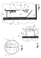
- FIG. 1 shows an example of a small wastewater treatment plant, intended for a decentralized use.
- the small sewage treatment plant has a container 1 with a feed pipe 2 in the container, a drain pipe 3 from the container 1 and a ventilation device 12.
- the container 1 is divided with a partition wall 13 into two chambers, wherein the chambers represent different treatment stages.
- the chamber 4 is used to carry out a mechanical pre-cleaning (primary treatment, sludge storage) and is therefore also to be considered as pre-clarification stage.
- the other chamber - the chamber 5 - is a biological treatment stage.
- the two treatment stages 4, 5 are connected to one another by means of an exemplarily illustrated passage 6 in the dividing wall 13, so that pre-clarified wastewater after the mechanical pre-cleaning, controlled by the hydraulic equilibrium, can run from the chamber 4 into the chamber 5.
- the passage 6 is an opening in the partition wall 13.
- a separating device 7 is installed, which is fastened in the illustrated embodiment with a holding device 16 on the partition wall 13 in a simple manner.
- the holding device 16 is designed as a hook, which over the upper end of the partition 13, as in FIG. 1 evident, attacks.
- a compressed air jack 9 or other conveyor device is installed as a clear water withdrawal pump.
- the separating device 7 is open in the lower region and has a correspondingly formed bevel 11 there. Furthermore, in an exemplary embodiment, one or more openings 10 are contained in the lower region of the separating device 7.
- Another compressed air lifter 8 or another conveyor device for pumping excess sludge from the biological stage 5 into the mechanical pre-cleaning 4 is preferably also at the separating device 7 attached.
- the resulting during operation of one or both conveyor oscillations are used to solve on the separator 7 or on the formed slope 11 sludge, so that this gravitationally back in the biological treatment stage 5 can get.
- the conveying devices 8, 9 are connected in a manner to the separating device 7, so that the vibrations arising during an operation thereof are transmitted to or induced in the separating device 7.
- the pre-clarified by the above processes wastewater passes from the mechanical pre-cleaning 4 through the opening 6 of the partition 13 in the biological treatment stage 5. There, the biological wastewater treatment takes place.
- the air required for the biological wastewater treatment process is supplied via an aerator 12 shown by way of example.
- the schematically illustrated aerator 12 is connected in a manner not shown to a compressor, is supplied to the ambient air for the purpose of ventilation in the biological treatment stage 5.
- biological treatment stage 5 is activated sludge, through which the pre-clarified wastewater is purified.
- the biological purified wastewater can leave the biological treatment stage 5 only by the separation device 7. In the separation device 7 there is a separation of the biologically purified wastewater from the activated sludge.
- one or more openings 10 are attached in a preferred embodiment in the lower region of the separator 7.
- the openings 10 can serve as an inflow and thus for establishing a hydraulic connection between the biological treatment stage 5 and the interior of the separating device 7.
- an influx mainly takes place through the openings 10, while the sedimented activated sludge sediments through the lower opening of the separator 7 and on the slope 7 out.
- the air lift 9 is arranged within the separator 7 such that its mouth-side opening is located in an upper portion of the separator.
- the compressed air lifter 9 conveys at predetermined intervals (for example, every 30 minutes) purified wastewater from the separator 7 in the sequence 3.
- the compressed air lifter 9 and the compressed air lifter 9 acting compressor is connected in a manner not shown to a control unit ,
- the separator 7 typically periodically in periods in which the wastewater in the separator 7 dwells without flow, so that in these periods, the separation of biologically purified wastewater and activated sludge without impairing flows can take place.
- the size of the separation device 7 and the time intervals between two clear water withdrawal processes in this case has a significant influence on the separation process between biologically purified wastewater and the activated sludge.
- the duration of the conveying process and the size of the separating device are matched to one another in such a way that only wastewater from the separating device is always challenged, which has already separated from the activated sludge in the period before the current conveying process. This avoids that during a current conveying process in the separation device 7 nachströmendes wastewater with activated sludge constituents can rise so far that the clear water withdrawal pump, which in the illustrated embodiment by the Air lifter 9 realized clear water is detected with contained activated sludge constituents.
- the compressed air lift 9 is installed in the separation device 7 in such a way that the amount of wastewater conveyed is limited to a lower water level 15, a problem-free separation process of biologically purified wastewater and activated sludge is provided.
- a problem-free separation process of biologically purified wastewater and activated sludge is provided.
- the container 1 via the supply line 2 flows in that increases in both chambers 4, 5, the water level, for example, to the level of the water level 14.
- the water level decreases
- the hydraulic connection to the pre-treatment 4 by means of the passage 6 simultaneously with the withdrawal of clear water from the separator 7 and the biological treatment 5 the same amount of pre-treated wastewater flows into the biological treatment stage. 5 one.
- the height-wise arrangement of the compressed air lift 9 in conjunction with the controller ensures that in a time interval in each case only a fixed amount is conveyed out of the separating device 7 out. This in turn ensures that the time required for the settling process is available. A hydraulic overload of the separator 7 is thus excluded.
- the additional placement of a float within the pre-treatment stage 4 can report a flood alarm or regulate ventilation times or control delivery periods of the compressed air lift 9.
- the container There is a container of 2 m diameter and a division into two chambers by a central partition, which divides the container into two equal halves. Connected to the container are four inhabitants with a daily waste water quantity of 150 l per inhabitant.
- the container has a water depth of 1.2 m.
- the surface area of each treatment step is approximately 1.5 m 2 .
- the average sewage inflow is 0.06 m 3 / h (the so-called Q 10 value).
- the separator has a length of 40 cm and a width of 30 cm and a height of 80 cm. This results in a volume of about 96 I in the separator.
- the clear water withdrawal pump is turned on for 30 minutes every 30 minutes in this example.
- the clear water withdrawal pump has a capacity of 30 l per minute.
- the upper portion of the separator is designed so that it protrudes, for example, 10 cm above the actual water level.
- the drain can prevent a corresponding sealing of the drain pipe, that here an overflow leads to the uncontrolled flow of wastewater with activated sludge.
- the process of biological wastewater treatment increases the activated sludge. This results in excess sludge, which is to promote in the field of mechanical pre-cleaning.
- This process is effected by the air lift 8.
- the air lift 8 is shown in the illustrated Embodiment attached to the separator 7.
- the distance 17 of the intake opening of the compressed air lift 8 causes at a correct distance 17 that each correct amount of excess sludge from the biological treatment stage is promoted out.
- the distance measure moves depending on the settling time for the mud between 10 and 50% of the water depth of the water level 15. Experiments have shown that especially the range between 20 and 30% of the water depth of the water level 15 is a preferred distance measure.
- the settled activated sludge amount which is within the distance measure 17 is the amount of activated sludge necessary for the correct operation of the biological stage 5.
- This amount of activated sludge within the distance 17 can not be promoted by the arrangement of the air lift 8 in the mechanical stage. Only the additionally occurring activated sludge, the so-called excess sludge, which goes beyond the distance 17, is conveyed by the compressed air lifter 8 in the mechanical stage. Due to this special feature, an always constant amount of activated sludge can be secured in the biological stage.
- the airlift 8 can also be used to cause a recirculation.
- the process of denitrification can be optimized.
- the oxidized in the biological stage ammonium can be denitrified under the ideal conditions (absence of atmospheric oxygen, sufficient carbon availability) in the mechanical precursor 4.
- the associated carbon degradation leads to a corresponding reduction in fan performance in the biological stage and to a corresponding Optimization of the pH value (nitrification reduces the pH value by releasing H + ions and the denitrification process can reverse this pH reduction).
- Another advantage of the arrangement is that on the compressed air lifter 8 in addition to the actual sludge production and purified or partially purified wastewater from the biological stage 5 is promoted in the mechanical precursor 4 and thus ensures that due to the hydraulic connection between the two stages 4, 5 carbonaceous wastewater enters the biological stage 5.
- the small wastewater treatment plant is only slightly loaded (under load operation)
- can be supplied by a corresponding recirculation the biological stage with carbon and other nutrients, so that the activated sludge remains active.
- this process ensures an equalization of load fluctuations.
- different delivery times and thus amounts of recirculation water, even for different loads can be set and realized.
- FIGS. 4 and 5 a separator 18 is shown according to another embodiment.
- the separator 18 is designed in principle as the separator 7 of the embodiment of FIGS. 1 to 3 ,
- the separation device 18 is also suspended in a biological treatment stage 5 of a small sewage treatment plant, by means of hooks, which separates the partition wall 13 between the two stages 4, 5.
- the separating device 18 is in FIG. 4 shown in a longitudinal section.
- the separating device 18 has above its slope 11.1 via a on the wall facing away from the partition wall 13 of the container 1 wall 21 inside guide element 19.
- the guide element 19 is inclined inwards in the direction of the slope 11.1.
- the baffle 19 thus forms with the inside of the aforementioned wall 21 of the separator 18 is a downwardly open receptacle 20.
- the receptacle 20 has in its upper end portion within the wall 21 of the separator 18 via one or more openings 22.
- the thus formed Receptacle 20 serves as an air bubble trap, specifically for receiving air bubbles which are introduced into the biological treatment stage 5 through the ventilation 12.1, when they enter through the lower-side opening of the separator 18 in this. These bubbles are trapped due to their tendency to rise. Background of the catching of above the slope 11.1 entering air bubbles within the receptacle 20 is that they do not enter the actual separation device 18, whereby the separation process between activated sludge and purified wastewater would be affected. Is exploited in this principle that the slope 11.1 prevents the ingress of air bubbles that rise vertically below the slope 11.1. This applies in principle also for the areas left open by the slope 11.1. However, it can not be completely prevented that air bubbles occur occasionally as a result of the opening adjoining the wall 21 on the underside of an operation of the ventilation 12.
- the guide element 19 is thus a built-in element which traps air bubbles entering in the manner of a chicane. These enter from the introduced into the wall 21 openings 22 again in the biological stage 5 a.
- the receptacle 20 as an air bubble trap is described above by way of example. For a person skilled in the art, numerous other embodiments result in the same effect, without these having to be described in more detail.
- the openings 10 and 10.1 can, if there is a risk that enter through these unwanted air bubbles in the interior of the respective separation device 7 and 18, also with an air bubble trap, as described in principle above, be equipped.
- the pumps used in the described embodiments can be kept height adjustable. Such height adjustment can be done depending on the liquid level within the respective separation device and thus within the biological treatment stage.
- the opening 6 can also be closed, so that the feeding of the biological treatment stage from the mechanical cleaning via a conveyor, preferably a compressed air lift takes place.
- the container can also be divided by partitions in three or four equal or different sized chambers.
- two or more containers, each with or without a partition represent different treatment levels.
- the different design can be used with the underlying method and the device in the existing distribution.
- a partition penetrating the opening may be present between the Vorschreibhave and the biological treatment stage in the upper part of the partition an open connection through which automatically pre-clarified wastewater from the Vor gleichhave when pumping clear water into the biological treatment stage.
- the separation device can also be provided as a chamber within the container, so that then no separate housing for the separation device must be made.
- the method described here and the devices described are also suitable for retrofitting existing containers, since the existing containers usually have corresponding openings in the partitions, which must be laboriously closed and sealed when retrofitted with conventional SBR systems.
- Another advantage of the short time intervals between two pumping operations of the clear water outlet is that only small amounts of water have to be stored in the system (just for the period between two pumping processes, ie, for example, for 30 minutes).
- valuable container volume for wastewater treatment can be used instead of being used for the storage of wastewater, as is the case with conventional SBR systems where the clear water withdrawal occurs only every six or every eight or every 12 hours or any other long period of time takes place.
Landscapes
- Life Sciences & Earth Sciences (AREA)
- Engineering & Computer Science (AREA)
- Water Supply & Treatment (AREA)
- Hydrology & Water Resources (AREA)
- Environmental & Geological Engineering (AREA)
- Chemical & Material Sciences (AREA)
- Organic Chemistry (AREA)
- Microbiology (AREA)
- Biodiversity & Conservation Biology (AREA)
- Mechanical Engineering (AREA)
- Health & Medical Sciences (AREA)
- Molecular Biology (AREA)
- Biological Treatment Of Waste Water (AREA)
- Activated Sludge Processes (AREA)
Abstract
Description
Gegenstand der Erfindung ist ein Verfahren zur Reinigung von Abwasser mittels einer Kleinkläranlage, insbesondere einer für einen dezentralen Einsatz vorgesehenen Kleinkläranlage, mit einem Zulauf, einer Vorklärstufe, einer biologischen Behandlungsstufe und einer der biologischen Behandlungsstufe zugeordneten Trennvorrichtung mit einem Klarwasserabzug, welches Verfahren prinzipiell nach einem Durchlaufverfahren durchgeführt wird. Ferner betrifft die Erfindung eine Kleinkläranlage, insbesondere für einen dezentralen Einsatz vorgesehene Kleinkläranlage, mit einem Zulauf, einer Vorklärstufe, einer biologischen Behandlungsstufe und einer der biologischen Behandlungsstufe zugeordneten Trennvorrichtung mit einem Klarwasserabzug. Des Weiteren betrifft die Erfindung eine Trennvorrichtung für eine solche Kleinkläranlage.The invention relates to a method for the purification of wastewater by means of a small sewage treatment plant, in particular provided for a decentralized use septic system, with an inlet, a pre-treatment, a biological treatment stage and the biological treatment stage associated separation device with a clear water, which method in principle by a continuous process is carried out. Furthermore, the invention relates to a small wastewater treatment plant, especially for a decentralized use intended small wastewater treatment plant, with an inlet, a pre-treatment, a biological treatment stage and the biological treatment stage associated separation device with a clear water outlet. Furthermore, the invention relates to a separation device for such a small wastewater treatment plant.
Kleinkläranlagen oder kleine Kläranlagen dienen der dezentralen Abwasserbeseitigung in ländlich strukturierten Gebieten, in denen aus wirtschaftlichen oder sonstigen Gründen heraus kein Kanalanschluss vorhanden ist oder hergestellt werden und daher eine zentrale Abwasserreinigung nicht erfolgen kann. Hier wird die aus den bestehenden gesetzlichen Verpflichtungen heraus resultierende Notwendigkeit einer Abwasserreinigung durch Kleinkläranlagen realisiert. Kleinkläranlagen sind in vielfältiger Weise technisch differenziert ausgestaltet. Als Kleinkläranlagen sind unter anderem Pflanzenkläranlagen, Tropfkörperanlagen, Festbettanlagen, Wirbelbettanlagen, Membrananlagen und SBR-Anlagen bekannt. Weit verbreitet sind zwischenzeitlich die so genannten SBR-Anlagen (Sequencing-Batch-Reactor bzw. sequenzielles biologisches Reinigungsverfahren).Small wastewater treatment plants or small wastewater treatment plants are used for decentralized wastewater disposal in rural areas where, for economic or other reasons, there is no sewer connection or production and therefore centralized wastewater treatment can not take place. Here, the need for wastewater treatment through small wastewater treatment plants resulting from the existing legal obligations is realized. Small wastewater treatment plants are designed in different ways technically differentiated. As a small wastewater treatment plants, inter alia, wetland plants, trickling filter plants, fixed bed plants, fluidized bed plants, membrane plants and SBR plants are known. Widely used are the meantime, the so-called SBR systems (S equencing- B atch- R eactor or s equenzielles b iologisches R agreement protocol).
Das SBR-Verfahren, auch Aufstauverfahren genannt, behandelt das Abwasser "portionsweise". Eine Kammer übernimmt die mechanische Vorklärung. Dort setzen sich die Schmutzpartikel als Schlamm ab. Danach wird das Abwasser in bestimmten Zeitabständen in den biologischen Klärbereich (in genannten SBR-Reaktor) transportiert und dort gereinigt. Zwischen der mechanischen Behandlungsstufe und der biologischen Behandlungsstufe besteht keine direkte Verbindung. Die Trennung zwischen gereinigtem Abwasser und dem Belebtschlamm findet in der gleichen Behandlungsstufe nur durch eine zeitliche Trennung der Vorgänge statt.The SBR process, also known as damming, treats wastewater "in portions". A chamber takes over the mechanical pre-treatment. There, the dirt particles settle as mud. Thereafter, the wastewater is transported at certain intervals in the biological treatment area (in said SBR reactor) and cleaned there. There is no direct connection between the mechanical treatment stage and the biological treatment stage. The separation between purified Wastewater and activated sludge take place in the same treatment stage only by a temporal separation of the processes.
Nachteilig wird bei nach dem SBR-Verfahren arbeitenden Kleinkläranlagen angesehen, dass die unterschiedlichen Wasserspiegel in den einzelnen Behandlungsstufen eine entsprechende Dichtigkeit der Trennwände erfordern. Insbesondere ist von Nachteil, dass bei Nachrüstung vorhandener Behälter vorhandene Durchlässe in den Trennwänden aufwändig verschlossen und abgedichtet werden müssen. Weiterhin sind Fördereinrichtungen notwendig, um das Abwasser aus der mechanischen Behandlungsstufe in die biologische Behandlungsstufe zu fördern. Zudem ist durch die Zykluszeit von 6 bis 12 Stunden (je nach Fabrikat) ein entsprechend großer Puffer notwendig, um das anfallende Abwasser entsprechend zwischenspeichern zu können. Weiterhin wird als nachteilig angesehen, dass bei den konventionellen SBR Systemen bei dem Klarwasserabzug große Wassermengen in kurzer Zeit in die der Kleinkläranlage nachgeschalteten Versickerungsanlagen gefördert werden. Viele Versickerungsanlagen können diese großen Wassermengen in den wenigen Minuten der Förderung nicht aufnehmen, so dass es hier zu einem Rückstau in die SBR Anlage und damit zu einem nicht gewünschten Aufwirbeln des abgesetzten Belebtschlammes kommt. Dies wiederum führt dazu, dass der aufgewirbelte Belebtschlamm während des Klarwasserabzuges in die Versickerungsanlage gefördert wird und diese dadurch zugesetzt wird. Eine aufwändige Sanierung ist die Folge.A disadvantage is considered in working after the SBR process wastewater treatment plants that the different water levels in the individual treatment stages require a corresponding tightness of the partitions. In particular, it is disadvantageous that, when retrofitting existing containers, existing passages in the partition walls must be lavishly sealed and sealed. Furthermore, conveyors are necessary to promote the wastewater from the mechanical treatment stage in the biological treatment stage. In addition, due to the cycle time of 6 to 12 hours (depending on the make), a correspondingly large buffer is required in order to be able to store the wastewater accordingly. Furthermore, it is considered disadvantageous that in the conventional SBR systems in the clear water discharge large amounts of water are promoted in a short time in the small wastewater treatment plant downstream infiltration systems. Many infiltration systems can not absorb these large amounts of water in the few minutes of production, so that there is a backflow into the SBR plant and thus to an undesired stirring up of the settled activated sludge. This in turn means that the fluidized activated sludge is conveyed during the clear water discharge in the infiltration system and this is thereby added. A complex renovation is the result.
Eine Alternative zu Reinigungsverfahren gemäß dem SBR-Prinzip stellt das im Markt bekannte so genannte CBR-Verfahren (Continuous-Batch-Reactor bzw. kontinuierliche biologische Reinigung) dar, bei dem im Gegensatz zum SBR-Verfahren die mechanische Vorreinigung und die biologische Behandlungsstufe über eine Öffnung miteinander verbunden sind, so dass Abwasser aus der mechanischen Behandlungsstufe direkt in die biologische Behandlungsstufe fließen kann. In einer in die biologische Behandlungsstufe eingehängten Trennvorrichtung (Separator) findet die notwendige Trennung zwischen gereinigtem Abwasser und Belebtschlamm statt. An die Trennvorrichtung ist eine Ablaufdrossel angebracht, die den Abfluss aus der Kläranlage begrenzt. Gesteuert wird bei dem CBR-Verfahren der Durchsatz durch den Zulauf. Dies hat zur Folge, dass, wenn mehr Abwasser der Kläranlage zufließt, als durch die Ablaufdrossel abfließen kann, der Behälter beziehungsweise die einzelnen Behandlungsstufen eingestaut werden. Der Überstau wird nach und nach durch den Abfluss aus der Drossel abgebaut.An alternative to purification processes according to the SBR principle is the so-called CBR process known in the marketplace ( C ontinuous B atch R eactor or continuous biological purification), in which, in contrast to the SBR process, the mechanical pre-cleaning and the biological Treatment stage are connected to each other via an opening so that wastewater from the mechanical treatment stage can flow directly into the biological treatment stage. In a suspended in the biological treatment stage separator (separator), the necessary separation between purified wastewater and activated sludge takes place. Attached to the separation device is an outlet throttle which limits the outflow from the sewage treatment plant. In the CBR process, the flow through the inlet is controlled. As a result, if more sewage of the sewage treatment plant flows, as can drain through the outlet throttle, the container or the individual treatment stages are stowed. The overflow is gradually reduced by the outflow from the throttle.
Nachteilig bei diesem Verfahren ist, dass in dem Separator zeitgleich die Absetzvorgänge des Schlammes (Abwärtsbewegungen) und dass ein Zustrom von zu der Drossel hin aufsteigendem Abwasser (Aufwärtsbewegung) stattfinden. Nur bei einer entsprechenden Differenz der Abwärtsgeschwindigkeit des Schlammes zu der Aufwärtsbewegung des Abwassers kann verhindert werden, dass Schlammbestandteile mit in den Ablauf kommen. Dabei funktioniert dieser Trennvorgang nur, wenn die Abwärtsgeschwindigkeit des Schlammes größer ist als die Aufwärtsbewegung des Abwassers. Da aber bekannt ist, dass die Absetzeigenschaften eines Schlammes durchaus variieren können, kann es hier zu Schlammabtrieb aufgrund fehlender Geschwindigkeitsdifferenzen kommen. Weiterhin ist von Nachteil, dass die Drosselvorrichtung verstopfen kann und somit auch größere Mengen Abwasser über den Notüberlauf fließen können. Sobald der Notüberlauf aktiv ist, steigt die Geschwindigkeit des aufwärtsströmenden Abwassers, so dass die Geschwindigkeit des aufwärtsströmenden Abwassers größer ist als die Geschwindigkeit des sich abwärts bewegenden Schlammes. Dies führt zu einem entsprechend massivem Schlammabtrieb und einer damit einhergehenden Gewässerverschmutzung sowie einem Verlust an Biomasse in dem biologischen Behandlungssystem.A disadvantage of this method is that in the separator at the same time take place the settling of the sludge (downward movements) and that an influx of rising to the throttle wastewater (upward movement) take place. Only with a corresponding difference in the downward velocity of the sludge to the upward movement of the wastewater can be prevented that sludge components come into the process. In this case, this separation process only works if the downward velocity of the sludge is greater than the upward movement of the wastewater. But since it is known that the Absetzzeigenschaften a sludge can vary quite well, this can lead to mud loss due to lack of speed differences. Another disadvantage is that the throttle device can clog and thus larger amounts of wastewater can flow through the emergency overflow. As soon as the emergency overflow is active, the velocity of the upflowing waste water increases, so that the velocity of the upflowing wastewater is greater than the velocity of the downwardly moving sludge. This leads to a correspondingly massive sludge output and associated water pollution as well as a loss of biomass in the biological treatment system.
Weiterhin ist bei dem CBR-Verfahren der Druckluftheber für den Überschussschlammabzug an die Luftleitung für die Belüftung gekoppelt. Dadurch wird bei jeder Belüftung Überschussschlamm aus der biologischen Stufe in die mechanische Stufe gefördert. Hierbei handelt es sich um einen ständigen Abzug von Belebtschlamm in die mechanische Stufe. Da aber Überschussschlamm nur in Abhängigkeit der jeweiligen Belastung entsteht, ist ein kontinuierlicher Abzug während der Belüftungsphase nicht geeignet, eine für das Verfahren erforderliche gleichbleibende bzw. ausreichende Belebtschlammmenge zu gewährleisten. Im Unterlastbetrieb wird zu viel Belebtschlamm in die mechanische Vorstufe befördert (bei Unterlast entsteht eben nur wenig Überschussschlamm, obwohl durch die permanente Überschussschlammförderung ständig Belebtschlamm in die mechanische Stufe gefördert wird), bei entsprechend hoher Last kann die feste Kopplung der Überschussschlammförderung an die Belüftung auch zu einer zu niedrigen Entnahme von Belebtschlamm und damit zu einem zu hohen Belebtschlammanteil in der biologischen Stufe führen.Furthermore, in the CBR process, the air lift for the excess sludge vent is coupled to the air duct for ventilation. As a result, excess sludge from the biological stage is conveyed to the mechanical stage at each aeration. This is a permanent deduction of activated sludge in the mechanical stage. However, since excess sludge only arises as a function of the respective load, a continuous withdrawal during the aeration phase is not suitable for ensuring a constant or sufficient amount of activated sludge required for the process. In under load operation, too much activated sludge is transported to the mechanical precursor (in case of underload, only a little surplus sludge is produced, although due to the permanent surplus sludge production, activated sludge constantly enters the sludge tank mechanical stage is promoted), with a correspondingly high load, the strong coupling of excess sludge production to the ventilation can also lead to too low a removal of activated sludge and thus to an excess of activated sludge in the biological stage.
Ausgehend von dem vorstehend diskutierten Stand der Technik liegt der Erfindung daher die Aufgabe zugrunde, ein Verfahren zur Reinigung von Abwasser mittels einer Kleinkläranlage sowie eine Kleinkläranlage vorzuschlagen, mit dem die zu den vorbeschriebenen SBR- und CBR-Verfahren aufgezeigten Nachteile vermieden, zumindest jedoch reduziert sind.Based on the prior art discussed above, the object of the invention is therefore to propose a method for purifying wastewater by means of a small sewage treatment plant and a small sewage treatment plant with which the disadvantages pointed out in relation to the above-described SBR and CBR processes are avoided, or at least reduced ,
Gelöst wird die verfahrensbezogene Aufgabe durch ein eingangs genanntes, gattungsgemäßes Verfahren, bei dem der Durchsatz der Anlage durch den Klarwasserabzug gesteuert wird, indem mittels einer durch eine Steuereinheit ansteuerbaren Pumpe, etwa eines Drucklufthebers diskontinuierlich Klarwasser aus der Trennvorrichtung abgezogen wird, wobei in einer Klarwasserförderperiode nur ein Bruchteil des in der Trennvorrichtung befindlichen Wassers als Klarwasser abgezogen wird, an welchen Klarwasserabzug der Zulauf von vorgeklärtem Abwasser aus der Vorklärstufe in die biologische Behandlungsstufe gekoppelt ist.The method-related object is achieved by an initially mentioned, generic method in which the throughput of the system is controlled by the clear water withdrawal by discontinuously clear water is withdrawn from the separator by means of a controllable by a control unit pump, such as a compressed air lifter, in a Klarwasserförderperiode only a fraction of the water present in the separator is withdrawn as clear water, to which clear water withdrawal the supply of pre-clarified wastewater from the pre-treatment stage is coupled into the biological treatment stage.
Die vorrichtungsbezogene Aufgabe wird erfindungsgemäß durch eine Kleinkläranlage gemäß dem Oberbegriff des Anspruchs 5 gelöst, bei der die Anlage über eine mit ihrer eingangsseitigen Mündung im oberen Bereich der Trennvorrichtung angeordnete Klarwasserabzugspumpe, etwa einen Druckluftheber verfügt.The device-related object is achieved by a small wastewater treatment plant according to the preamble of
Unter dem im Oberbegriff des unabhängigen Anspruch benutzten Begriff, dass das Verfahren prinzipiell nach einem Durchlaufverfahren durchgeführt wird, ist im Rahmen dieser Ausführungen zur Unterscheidung gegenüber einem SBR-Verfahren zu verstehen. Somit umfasst dieser Begriff einen Betrieb einer Kleinkläranlage, in der eine Reinigung nicht chargenweise (batchweise) und demzufolge ein Flüssigkeitswechsel batchweise in einer Stufe erfolgt. Somit sind unter diesem Begriff sämtliche Verfahren zum Betrieb einer Kleinkläranlage zu verstehen, bei denen im weitesten Sinne ein kontinuierlicher Durchsatz vorgesehen ist. Dieses Verfahren beinhaltet, bei denen, wie beansprucht ein Klarwasserabzug periodisch vorgenommen wird und mit einem solchen Klarwasserabzug nur einen Teil des in einer Trennvorrichtung befindlichen Flüssigkeit abgezogen wird. Der in diesem Zusammenhang verwendete Begriff eines Durchlaufverfahrens bezieht sich nicht auf eine notwendige hydraulische Verbindung der einzelnen Prozessbecken bzw. Stufen.Under the term used in the preamble of the independent claim that the method is carried out in principle by a continuous process, is to be understood in the context of these statements to distinguish it from an SBR process. Thus, this term includes operation of a small wastewater treatment plant, in which a cleaning is not batchwise and thus a liquid change batchwise in one stage. Thus, this term means all processes for operating a small wastewater treatment plant, in which a continuous throughput is provided in the broadest sense. This method involves using as claimed a clear water withdrawal periodically is withdrawn and with such a clear water withdrawal only a part of the liquid contained in a separator. The term of a continuous process used in this context does not refer to a necessary hydraulic connection of the individual process tanks or stages.
Bei dem beanspruchten Verfahren wird ein Klarwasserabzug aktiv betrieben. Als Aktor zum Abziehen von Klarwasser aus der Trennvorrichtung wird eine Pumpe, beispielsweise ein Druckluftheber verwendet. Dieser wird auch aus Energiespargründen diskontinuierlich betrieben. Die Pumpe ist durch eine die Prozesse der Kleinkläranlage steuernde Steuereinheit ansteuerbar. Die Klarwasserförderperioden zum Abziehen von Klarwasser aus der Trennvorrichtung sind zeitlich so bemessen, dass nur ein Bruchteil der in der Trennvorrichtung befindlichen Flüssigkeit - das Klarwasser - abgezogen wird. Abgezogen wird das Klarwasser aus der Trennvorrichtung aus seinem obersten Bereich. Mithin ist der mündungsseitige Eingang der bei einer solchen Kleinkläranlage vorhandenen Klarwasserabzugspumpe in diesem Bereich der Trennvorrichtung angeordnet. Bei diesem Verfahren ist ferner vorgesehen, dass der Zufluss von vorgeklärtem Abwasser aus der Vorklärstufe in die biologische Behandlungsstufe an den Vorgang eines Klarwasserabzuges gekoppelt ist. Eine solche Kopplung kann beispielsweise hydraulisch erfolgen, und zwar dergestalt, dass allein aufgrund des sinkenden Flüssigkeitsspiegels in der Trennvorrichtung und damit in der biologischen Behandlungsstufe ein Nachströmen von vorgeklärtem Abwasser aus der Vorklärstufe in die biologische Behandlungsstufe selbsttätig erfolgt. Selbstverständlich ist es ebenfalls möglich, Abwasser aus der Vorklärstufe mittels einer Pumpe, beispielsweise einem Druckluftheber, in die biologische Behandlungsstufe zu fördern. Bei einer solchen Ausgestaltung besteht die Möglichkeit, den Zufluss von vorgeklärtem Abwasser in die biologische Behandlungsstufe zeitlich versetzt zu dem Klarwasserabzug durchzuführen. Auch ein solcher Zufluss ist an den Klarwasserabzug gekoppelt.In the claimed process, a clear water discharge is actively operated. As an actuator for removing clear water from the separator, a pump, such as a compressed air lift is used. This is operated intermittently also for energy saving reasons. The pump can be activated by a control unit controlling the processes of the small wastewater treatment plant. The clear water delivery periods for removing clear water from the separator are timed so that only a fraction of the liquid contained in the separator - the clear water - is deducted. The clear water is removed from the separator from its uppermost area. Consequently, the mouth-side entrance of the present in such a small sewage treatment plant clear water withdrawal pump is arranged in this area of the separator. In this method, it is further provided that the inflow of pre-clarified wastewater from the pre-treatment stage in the biological treatment stage is coupled to the process of clear water discharge. Such a coupling can be carried out hydraulically, for example, in such a way that, on account of the sinking liquid level in the separating device and thus in the biological treatment stage, a subsequent flow of pre-clarified waste water from the preliminary clarification stage into the biological treatment stage takes place automatically. Of course, it is also possible to promote wastewater from the Vorklärstufe by means of a pump, such as a compressed air lift, in the biological treatment stage. In such an embodiment, it is possible to carry out the inflow of pre-clarified wastewater in the biological treatment stage with a time offset to the clear water withdrawal. Such an inflow is coupled to the clear water outlet.
Die Trennvorrichtung kann innerhalb der biologischen Behandlungsstufe angeordnet sein. Gleichfalls ist es möglich, diese der biologischen Behandlungsstufe nachzuschalten. Vorzugsweise stehen die Trennvorrichtung und die biologische Behandlungsstufe in einer hydraulischen Verbindung miteinander. Bevorzugt ist eine Ausgestaltung, bei der die Trennvorrichtung innerhalb der biologischen Reinigungsstufe angeordnet ist.The separation device can be arranged within the biological treatment stage. Likewise, it is possible to follow this to the biological treatment stage. Preferably, the separation device and the biological treatment stage are in a hydraulic connection together. Preferred is an embodiment in which the separation device is arranged within the biological purification stage.
Bei einem Betrieb der Anlage wird in dem zur Trennung von gereinigtem Abwasser und dem Belebtschlamm abgetrennten Teil das gereinigte Abwasser in typischerweise kurzen Zeitintervallen mit einer Fördereinrichtung aus der Anlage gefördert. Das zwischen den Fördervorgängen sich in den Behandlungsstufen ansammelnde Abwasser wird dabei eingestaut, da die einzelnen Behandlungsstufen über entsprechende Verbindungsöffnungen oder Leitungen miteinander verbunden sind. Der sich in der Trennvorrichtung zur Trennung von gereinigtem Abwasser und Belebtschlamm im unteren Bereich der Trennvorrichtung ansammelnde Belebtschlamm gelangt über eine entsprechend ausgebildete Ableitungsvorrichtung wieder in den Bereich der biologischen Abwasserbehandlung, so dass hierüber der notwendige Rücklaufschlammkreislauf geschlossen wird. Der notwendige Abzug von Überschussschlamm aus der biologischen Behandlungsstufe in den Bereich der mechanischen Behandlungsstufe erfolgt dabei vorzugsweise nach einer Belüftungspause von mindestens 15 Minuten, optimal nach einer Belüftungspause zwischen 30 oder 90 Minuten in den Nachtstunden. Dabei ist die Ansaugöffnung der Überschussschlammpumpe einer bevorzugten Ausführung in einem definierten Abstand von der Sohle der biologischen Behandlungsstufe anzubringen, damit die zum Betrieb der biologischen Stufe notwendige Schlammmenge unterhalb der Ansaugöffnung stets verbleibt und nur der tatsächlich überschüssige Schlamm, der oberhalb dieses Niveaus liegt, in die mechanische Behandlungsstufe gefördert wird. Dadurch kann ein gleich bleibender Gehalt an Belebtschlamm in der Anlage gewährleistet werden.During operation of the plant, in the part separated for the separation of purified wastewater and the activated sludge, the treated wastewater is conveyed out of the plant in typically short time intervals with a conveyor. The accumulating between the conveying processes in the treatment stages wastewater is thereby reined, since the individual treatment stages are connected to each other via corresponding connection openings or lines. The activated sludge accumulating in the separating device for the separation of purified wastewater and activated sludge in the lower region of the separating device passes through an appropriately designed discharge device back into the area of biological wastewater treatment, so that the necessary return sludge cycle is closed. The necessary deduction of excess sludge from the biological treatment stage in the region of the mechanical treatment stage is preferably carried out after a ventilation break of at least 15 minutes, optimally after a ventilation break between 30 or 90 minutes in the night hours. In this case, the suction opening of the excess sludge pump of a preferred embodiment at a defined distance from the bottom of the biological treatment stage to install, so that the operation of the biological stage necessary amount of sludge always remains below the intake and only the actual excess sludge, which is above this level, in the mechanical treatment stage is promoted. This ensures a constant level of activated sludge in the system.
In einer vorzugsweisen Ausgestaltung wird einer oder zwei der einzubauenden Fördereinrichtungen, möglichst in Form von Drucklufthebern, an der Trennvorrichtung direkt befestigt, so dass die während des Fördervorganges übertragenen Schwingungen an der Trennvorrichtung anhaftende Schlammpartikel lösen.In a preferred embodiment, one or two of the conveyors to be installed, if possible in the form of compressed air lifts, directly attached to the separator, so that the transmitted during the conveying process vibrations on the separator dissolving mud particles.
Weiterhin kann mit einer vorzugsweise Ausgestaltung der Fördereinrichtung für den Klarwasserabzug mit einer entsprechend ausgebildeten Ansaugöffnung sich möglicherweise angesammelter Schwimmschlamm direkt mit heraus gefördert werden, so dass es hier nicht zu einer Ansammlung größerer Schwimmschlamm Mengen kommt, die eine entsprechende Probennahme in der Trennvorrichtung erschweren. In einer alternativen Ausgestaltung kann die Ansaugöffnung auch so ausgebildet sein, dass durch ein entsprechend getauchtes Rohr keine Schwimmstoffe in die Fördervorrichtung gelangen können.Furthermore, with a preferred embodiment of the conveyor for the clear water outlet with a correspondingly shaped suction possibly accumulated scum directly be promoted out with, so that it does not come to an accumulation of larger quantities of scum that complicate a corresponding sampling in the separator. In an alternative embodiment, the suction opening may also be formed so that no floating substances can enter the conveying device through a correspondingly dipped tube.
In einer besonderen Ausgestaltung kann die Verbindung zwischen der mechanischen Vorbehandlung und der biologischen Stufe unterbrochen sein, so dass das mechanisch vorgereinigte Abwasser ebenfalls durch eine Fördereinrichtung in kurzen Zeitabständen beziehungsweise in Zeitabständen, die an die Klarwasser Fördervorgänge angepasst sind, in die biologische Behandlungsstufe gefördert wird.In a particular embodiment, the connection between the mechanical pretreatment and the biological stage may be interrupted, so that the mechanically pre-treated wastewater is also conveyed by a conveyor in short time intervals or at intervals, which are adapted to the clear water production processes in the biological treatment stage.
Einfluss auf die Länge der Klarwasserabzugsperioden und/oder der zwischen zwei Klarwasserabzugsperioden befindlichen Pausen - also den Perioden, in denen kein Klarwasser abgezogen wird - kann der in der Vorklärstufe vorhandene Flüssigkeitsspiegel von darin befindlichem Abwasser sein. Gleichfalls besteht die Möglichkeit, die Länge von Klarwasserabzugsperioden und/oder zwischen zwei Klarwasserabzugsperioden befindlicher Pausen in Abhängigkeit von einer Änderung des in der Vorklärstufe befindlichen Flüssigkeitsspiegels zu steuern.Influence on the length of the clear water withdrawal periods and / or the pauses between two clear water withdrawal periods - ie the periods in which no clear water is withdrawn - may be the liquid level of wastewater present in the pre-treatment stage. It is likewise possible to control the length of clear water withdrawal periods and / or pauses between two clear water withdrawal periods as a function of a change in the liquid level present in the pre-clarification stage.
Weitere Vorteile und Ausgestaltungen der Erfindung ergeben sich aus der nachfolgenden Beschreibung von Ausführungsbeispielen unter Bezugnahme auf die beigefügten Figuren. Es zeigen:
- Fig. 1:
- einen schematisierten Querschnitt durch eine Kleinkläranlage,
- Fig. 2:
- einen weiteren Querschnitt durch die
Kleinkläranlage der Figur 1 , wobei die Schnittebene gegenüber der Schnittdarstellung der Fi-gur 1 um 90 Grad versetzt ist, - Fig. 3:
- eine geschnittene Draufsicht auf die
Kleinkläranlage der Figuren 1 und 2 , - Fig. 4:
- einen Ausschnitt aus einer weiteren Kleinkläranlage, die prinzi- piell derjenigen der
Figur 1 entspricht, zum Darstellen einer darin befindlichen Trennvorrichtung mit ihrem Klarwasserabzug und - Fig. 5:
- eine Draufsicht auf die
Trennvorrichtung der Figur 4 .
- Fig. 1:
- a schematic cross section through a small wastewater treatment plant,
- Fig. 2:
- another cross section through the small wastewater treatment plant of
FIG. 1 , wherein the sectional plane is offset from the sectional view of FIG. 1 by 90 degrees, - 3:
- a sectional plan view of the small wastewater treatment plant of
Figures 1 and 2 . - 4:
- a section of another small sewage treatment plant, the pri- especially those of
FIG. 1 corresponds to representing a separation device therein with its clear water outlet and - Fig. 5:
- a plan view of the separator of the
FIG. 4 ,
In der biologischen Behandlungsstufe ist eine Trennvorrichtung 7 eingebaut, die bei dem dargestellten Ausführungsbeispiel mit einer Haltevorrichtung 16 an der Trennwand 13 auf einfache Weise befestigt ist. Die Haltevorrichtung 16 ist als Haken konzipiert, die über den oberen Abschluss der Trennwand 13, wie in
Ein weiterer Druckluftheber 8 oder eine sonstige Förderervorrichtung zur Förderung von Überschussschlamm aus der biologischen Stufe 5 in die mechanische Vorreinigung 4 ist vorzugsweise ebenfalls an der Trennvorrichtung 7 befestigt. Neben einer einfachen Montage, die die in der biologischen Reinigungsstufe 5 angeordnete Trennvorrichtung 7 bietet, werden die beim Betrieb einer oder beider Fördereinrichtung entstehenden Schwingungen genutzt, um an der Trennvorrichtung 7 oder an der ausgebildeten Schräge 11 anhaftenden Schlamm zu lösen, damit dieser schwerkraftbedingt wieder in die biologische Behandlungsstufe 5 gelangen kann. Um dieses zu ermöglichen versteht es sich, dass die Fördereinrichtungen 8, 9 in einer Art und Weise an die Trennvorrichtung 7 angeschlossen sind, damit die bei einem Betrieb derselben entstehenden Schwingungen auf die Trennvorrichtung 7 übertragen bzw. in diese induziert werden.Another compressed air lifter 8 or another conveyor device for pumping excess sludge from the
Nachfolgend ist die Funktionsweise der Kleinkläranlage 1 beschrieben:The operation of the small
Anfallendes Abwasser wird dem Behälter 1 mit dem Zulaufrohr 2 zugeführt und gelangt somit in die mechanische Vorreinigung 4. Dort trennen sich Stoffe, deren spezifisches Gewicht sich vom Abwasser unterscheidet, durch Absetzvorgänge vom Abwasser. Stoffe mit einem höheren spezifischen Gewicht sedimentieren und sammeln sich im unteren Bereich der mechanischen Vorreinigung 4. Der so abgesetzte Schlamm wird z. B. jährlich oder bedarfsgerecht von einem Saugwagen entfernt. Stoffe mit einem geringeren spezifischen Gewicht als Wasser schwimmen auf.Accumulating wastewater is fed to the
Das durch die vorbeschriebenen Vorgänge vorgeklärte Abwasser gelangt aus der mechanischen Vorreinigung 4 durch die Öffnung 6 der Trennwand 13 in die biologische Behandlungsstufe 5. Dort findet die biologische Abwasserreinigung statt. Die zum biologischen Abwasserreinigungsprozess notwendige Luft wird über einen beispielhaft dargestellten Belüfter 12 zugeführt. Der schematisiert dargestellte Belüfter 12 ist in nicht näher dargestellter Art und Weise an einen Verdichter angeschlossen, mit dem Umgebungsluft für die Zwecke der Belüftung in die biologische Behandlungsstufe 5 zugeführt wird. In der biologischen Behandlungsstufe 5 befindet sich Belebtschlamm, durch den das vorgeklärte Abwasser gereinigt wird. Das biologische gereinigte Abwasser kann die biologische Behandlungsstufe 5 nur durch die Trennvorrichtung 7 verlassen. In der Trennvorrichtung 7 findet eine Trennung des biologisch gereinigten Abwassers von dem Belebtschlamm statt. Aufgrund des Dichteunterschiedes sinkt der Belebtschlamm in der Trennvorrichtung 7 nach unten und gelangt über die ausgebildete Schräge 11 wieder zurück in die biologische Behandlungsstufe 5. Um den Absetzvorgang in möglichst geringem Maß zu beeinträchtigen, sind in einer vorzugsweisen Ausgestaltung im unteren Bereich der Trennvorrichtung 7 eine oder mehrere Öffnungen 10 angebracht. Die Öffnungen 10 können als Zufluss und somit zum Herstellen einer hydraulischen Verbindung zwischen der biologischen Behandlungsstufe 5 und dem Inneren der Trennvorrichtung 7 dienen. Somit erfolgt ein Zustrom vornehmlich durch die Öffnungen 10 hinweg, während der sedimentierte Belebtschlamm durch die untere Öffnung der Trennvorrichtung 7 hindurch und auf die Schräge 7 hin sedimentiert.The pre-clarified by the above processes wastewater passes from the
Der Druckluftheber 9 ist innerhalb der Trennvorrichtung 7 dergestalt angeordnet, damit sich seine mündungsseitige Öffnung in einem oberen Abschnitt der Trennvorrichtung befindet.The air lift 9 is arranged within the separator 7 such that its mouth-side opening is located in an upper portion of the separator.
Der Druckluftheber 9 fördert in vorbestimmten Zeitabständen (beispielsweise alle 30 Minuten) gereinigtes Abwasser aus der Trennvorrichtung 7 in den Ablauf 3. Zu diesem Zweck ist der Druckluftheber 9 bzw. der den Druckluftheber 9 beaufschlagende Verdichter in nicht näher dargestellter Art und Weise an eine Steuereinheit angeschlossen. Durch das periodische Fördern von Abwasser des in der Trennvorrichtung 7 typischerweise regelmäßig in Zeiträumen, in denen das Abwasser in der Trennvorrichtung 7 ohne Fließbewegung verweilt, so dass in diesen Zeiträumen die Trennung von biologisch gereinigtem Abwasser und Belebtschlamm ohne beeinträchtigende Strömungen stattfinden kann. Die Größe der Trennvorrichtung 7 sowie die Zeitabstände zwischen zwei Klarwasserabzugsvorgängen hat hierbei maßgeblichen Einfluss auf den Trennungsvorgang zwischen biologisch gereinigtem Abwasser und dem Belebtschlamm. Die Dauer des Fördervorganges sowie die Größe der Trennvorrichtung sind dergestalt aufeinander abgestimmt, das nur immer Abwasser aus der Trennvorrichtung herausgefordert wird, welches sich bereits in den Zeitraum vor dem aktuellen Fördervorgang von dem Belebtschlamm getrennt hat. Damit wird vermieden, dass während eines aktuellen Fördervorganges in die Trennvorrichtung 7 nachströmendes Abwasser mit Belebtschlammbestandteilen so weit aufsteigen kann, dass die Klarwasserabzugspumpe, die bei dem dargestellten Ausführungsbeispiel durch den Druckluftheber 9 realisiert ist Klarwasser mit noch enthaltenen Belebtschlammbestandteilen erfasst. Wird in einer beispielhaften Ausgestaltung der Druckluftheber 9 in der Trennvorrichtung 7 so eingebaut, dass die geförderte Abwassermenge begrenzt ist auf ein unteres Wasserniveau 15, ist ein problemloser Trennungsvorgang von biologisch gereinigtem Abwasser und Belebtschlamm gegeben. Zwischen zwei Fördervorgängen des Drucklufthebers 9 sorgt Abwasser, welches in dieser Zeit den Behälter 1 über die Zulaufleitung 2 zufließt dafür, dass in beiden Kammern 4, 5 der Wasserspiegel ansteigt, beispielsweise auf das Niveau des Wasserspiegels 14. Bei dem nächsten Fördervorgang sinkt der Wasserspiegel in der Trennvorrichtung 7 und damit in der biologischen Behandlungsstufe 5. Infolge der hydraulischen Verbindung zu der Vorklärstufe 4 mittels des Durchganges 6 strömt gleichzeitig mit dem Abzug von Klarwasser aus der Trennvorrichtung 7 bzw. der biologischen Reinigungsstufe 5 dieselbe Menge an vorgeklärtem Abwasser in die biologische Behandlungsstufe 5 ein. Durch die Steuerung kann dabei die Laufzeit für den Druckluftheber 9 begrenzt werden. Damit sorgt die höhenmäßige Anordnung des Drucklufthebers 9 in Verbindung mit der Steuerung dafür, dass in einem Zeitintervall jeweils nur eine fest definierte Menge aus der Trennvorrichtung 7 heraus gefördert wird. Dies wiederum gewährleistet, dass für den Absetzvorgang der jeweils erforderliche Zeitraum zur Verfügung steht. Eine hydraulische Überlastung der Trennvorrichtung 7 ist damit ausgeschlossen. Das zusätzliche Anordnen eines Schwimmers innerhalb der Vorklärstufe 4 kann einen Hochwasseralarm melden oder Belüftungszeiten regulieren oder Förderzeiträume des Drucklufthebers 9 steuern.The compressed air lifter 9 conveys at predetermined intervals (for example, every 30 minutes) purified wastewater from the separator 7 in the
Der vorstehend beschriebene Prozess soll aufgrund seiner Relevanz nachfolgend an einem Beispiel verdeutlicht werden:Due to its relevance, the process described above should be illustrated by an example below:
Vorhanden ist ein Behälter mit 2 m Durchmesser und eine Aufteilung in zwei Kammern durch eine mittige Trennwand, die den Behälter in zwei gleichgroße Hälften aufgeteilt. An den Behälter angeschlossen sind vier Einwohner mit einer täglichen Abwassermenge von 150 I pro Einwohner. Der Behälter hat eine Wassertiefe von 1,2 m. Die Oberfläche jeder Behandlungsstufe beträgt circa 1,5 m2. Der durchschnittliche Abwasserzufluss beträgt 0,06 m3/h (der so genannte Q10 Wert). Die Trennvorrichtung hat eine Länge von 40 cm und einer Breite von 30 cm und eine Höhe von 80 cm. Damit ergibt sich ein Volumen von circa 96 I in der Trennvorrichtung. Die Klarwasserabzugspumpe wird in diesem Beispiel alle 30 Minuten für je eine Minute eingeschaltet. Die Klarwasserabzugspumpe hat eine Förderleistung von 30 I pro Minute. Während die Klarwasserabzugspumpe diese 30 I gereinigtes Abwasser aus der Trennvorrichtung in den Ablauf der Anlage fördert, strömen im unteren Bereich der Trennvorrichtung eben diese 30 I nach, wobei diese nachströmende Menge noch ein Gemisch aus gereinigtem Abwasser und Belebtschlamm darstellt. Durch die Größe der Trennvorrichtung von circa 96 I verweilt das Abwasser circa 1,5 Stunden durchschnittlich in der Trennvorrichtung (umgerechnet mit einer Entnahme von 30 I pro halbe Stunde und einem Volumen der Trennvorrichtung von circa 96 I). Diese beispielhafte Berechnung verdeutlicht, dass durch das Förderintervall, die Fördermenge sowie das Volumen der Trennvorrichtung stets eine entsprechende Absetzzeit für eine gesicherte Trennung von gereinigtem Abwasser und Schlamm gewährleistet ist. Gleichzeitig ist gewährleistet, dass aus der Anlage immer nur aus dem oberen Bereich gereinigtes Abwasser ohne Belebtschlamm heraus gefördert wird. In dem Beispiel ergibt sich ein rechnerischer Aufstau in beiden Behandlungsstufen von circa 1 Zentimeter (in einer Stunde fließen theoretisch circa 60 I Abwasser der Anlage zu, somit in einer halben Stunde zirka 30 I). Zwischen zwei Fördervorgängen für den Klarwasserabzug sammeln sich somit jeweils zirka 30 I an. Dadurch, dass beide Behandlungsstufen mit einem Durchlass hydraulisch miteinander verbunden sind, ergibt sich bei einer Oberfläche von rund 3 m2 ein Einstau bzw. Aufstau von 1 Zentimeter. Die Trennvorrichtung, der Druckluftheber für den Klarwasserabzug sowie der Ablauf sind dabei so gestaltet, dass auch ein höherer Einstau (z.B. bei einem Badewannenstoß oder einem sonstigen erhöhten hydraulischen Zulauf) keine Probleme verursacht. Hierzu wird der obere Bereich der Trennvorrichtung so konstruiert, dass er zum Beispiel 10 cm über dem eigentlichen Wasserspiegel hinausragt. Am Ablauf kann eine entsprechende Abdichtung des Ablaufrohres verhindern, dass hier ein Überstau zum unkontrollierten Abfließen von Abwasser mit Belebtschlamm führt.There is a container of 2 m diameter and a division into two chambers by a central partition, which divides the container into two equal halves. Connected to the container are four inhabitants with a daily waste water quantity of 150 l per inhabitant. The container has a water depth of 1.2 m. The surface area of each treatment step is approximately 1.5 m 2 . The average sewage inflow is 0.06 m 3 / h (the so-called Q 10 value). The separator has a length of 40 cm and a width of 30 cm and a height of 80 cm. This results in a volume of about 96 I in the separator. The clear water withdrawal pump is turned on for 30 minutes every 30 minutes in this example. The clear water withdrawal pump has a capacity of 30 l per minute. While the clear water withdrawal pump promotes this 30 l of purified wastewater from the separator in the flow of the plant, flow in the lower part of the separator just these 30 I, this inflowing amount is still a mixture of purified wastewater and activated sludge. Due to the size of the separation device of about 96 l, the wastewater lingers for about 1.5 hours on average in the separation device (converted with a withdrawal of 30 l per half hour and a volume of the separation device of about 96 l). This exemplary calculation makes it clear that a corresponding settling time for a reliable separation of purified wastewater and sludge is always ensured by the delivery interval, the delivery rate and the volume of the separation device. At the same time, it is ensured that wastewater purified from the plant is only pumped out of the upper area without activated sludge. In the example, a calculated accumulation results in both treatment steps of about 1 centimeter (in one hour theoretically about 60 l of waste water flow to the system, thus in about half an hour about 30 l). In each case, approximately 30 l accumulate between two pumping processes for clear water discharge. The fact that both treatment stages are hydraulically connected to one another with a passage, resulting in a surface of about 3 m 2, a jam or accumulation of 1 centimeter. The separator, the compressed air lift for the clear water outlet and the drain are designed so that even a higher congestion (eg in a bathtub shock or other increased hydraulic inlet) causes no problems. For this purpose, the upper portion of the separator is designed so that it protrudes, for example, 10 cm above the actual water level. At the drain can prevent a corresponding sealing of the drain pipe, that here an overflow leads to the uncontrolled flow of wastewater with activated sludge.
Durch den Prozess der biologischen Abwasserreinigung vermehrt sich der Belebtschlamm. Es entsteht dabei Überschussschlamm, der in den Bereich der mechanischen Vorreinigung zu fördern ist. Dieser Vorgang wird durch den Druckluftheber 8 bewirkt. Der Druckluftheber 8 ist bei dem dargestellten Ausführungsbeispiel an der Trennvorrichtung 7 befestigt. Der Abstand 17 der Ansaugöffnung des Drucklufthebers 8 bewirkt bei einem korrekten Abstandsmaß 17, dass jeweils die korrekte Menge an Überschussschlamm aus der biologischen Behandlungsstufe heraus gefördert wird. Das Abstandsmaß bewegt sich in Abhängigkeit der Absetzzeit für den Schlamm zwischen 10 und 50% der Wassertiefe des Wasserspiegels 15. Versuche haben gezeigt, dass speziell der Bereich zwischen 20 und 30% der Wassertiefe des Wasserspiegels 15 ein bevorzugtes Abstandsmaß darstellt. Die abgesetzte Belebtschlammmenge, die sich innerhalb des Abstandsmaßes 17 befindet, ist die zum korrekten Betrieb der biologischen Stufe 5 notwendige Belebtschlammmenge. Diese Belebtschlammmenge innerhalb des Abstandsmaßes 17 kann durch die Anordnung des Drucklufthebers 8 nicht in die mechanische Stufe gefördert werden. Nur der zusätzlich entstehende Belebtschlamm, der so genannte Überschussschlamm, der über das Abstandsmaß 17 hinausgeht, wird von dem Druckluftheber 8 in die mechanische Stufe gefördert. Durch diese Besonderheit kann eine stets gleich bleibende Belebtschlammmenge in der biologischen Stufe gesichert werden.The process of biological wastewater treatment increases the activated sludge. This results in excess sludge, which is to promote in the field of mechanical pre-cleaning. This process is effected by the air lift 8. The air lift 8 is shown in the illustrated Embodiment attached to the separator 7. The
Für den Überschussschlammabzug ist es erforderlich, einmal oder mehrmals am Tag die Belüftung durch eine entsprechende Programmierung in der Steuerung für einen Zeitraum zu unterbrechen, damit sich der Belebtschlamm in der biologischen Behandlungsstufe absetzen und der Druckluftheber 8 die über das Abstandsmaß 17 hinausgehende Menge an Belebtschlamm als Überschussschlamm in die mechanische Stufe fördern kann.For the excess sludge removal, it is necessary once or several times a day to interrupt the ventilation by a corresponding programming in the controller for a period of time to settle the activated sludge in the biological treatment stage and the airlift 8 the amount of activated sludge exceeding the
Der Druckluftheber 8 kann zudem dazu genutzt werden, eine Rezirkulation zu bewirken. Dadurch, dass über den Druckluftheber neben der eigentlichen Schlammförderung auch gereinigtes beziehungsweise teilgereinigtes Abwasser aus der biologischen Stufe in die mechanische Vorstufe 4 gefördert wird, kann der Prozess der Denitrifikation optimiert werden. Das in der biologischen Stufe oxidierte Ammonium kann unter den idealen Bedingungen (Abwesenheit von Luftsauerstoff, ausreichendes Kohlenstoffdargebot) in der mechanischen Vorstufe 4 denitrifiziert werden. Der damit einhergehende Kohlenstoffabbau führt zu einer entsprechenden Reduktion an Gebläseleistung in der biologischen Stufe sowie zu einer entsprechenden Optimierung des pH Wertes (durch die Nitrifikation wird durch das freisetzen von H+ Ionen der pH-Wert abgesenkt; durch den Prozess der Denitrifikation kann diese pH-Wert Absenkung wieder aufgehoben werden).The airlift 8 can also be used to cause a recirculation. As a result of the fact that purified or partially purified wastewater from the biological stage is conveyed into the
Ein weiterer Vorteil der Anordnung besteht darin, dass über den Druckluftheber 8 neben der eigentlichen Schlammförderung auch gereinigtes beziehungsweise teilgereinigtes Abwasser aus der biologischen Stufe 5 in die mechanische Vorstufe 4 gefördert wird und damit dafür sorgt, dass infolge der hydraulischen Verbindung zwischen den beiden Stufen 4, 5 kohlenstoffhaltiges Abwasser in die biologische Stufe 5 gelangt. Insbesondere im Zeiträumen, in denen die Kleinkläranlage nur gering belastet wird (Unterlastbetrieb), kann durch eine entsprechende Rezirkulation die biologische Stufe mit Kohlenstoff und sonstigen Nährstoffen versorgt werden, so dass der Belebtschlamm aktiv bleibt. Weiterhin sorgt dieser Vorgang für eine Vergleichmäßigung von Belastungsschwankungen. In Verbindung mit einer entsprechend programmierten Steuerung können verschiedene Förderzeiten und damit Rezirkulationswassermengen, auch für unterschiedliche Belastungen, eingestellt und verwirklicht werden.Another advantage of the arrangement is that on the compressed air lifter 8 in addition to the actual sludge production and purified or partially purified wastewater from the
In den
Bei dem Leitelement 19 handelt es sich somit um ein Einbauelement, welches nach Art einer Schikane eintretende Luftblasen fängt. Diese treten aus den in die Wand 21 eingebrachten Durchbrechungen 22 wieder in die biologische Stufe 5 ein. Die Aufnahme 20 als Luftblasenfalle ist vorstehend beispielhaft beschrieben. Für einen Fachmann ergeben sich zahlreiche andere Ausgestaltungen, dasselbe zu bewirken, ohne dass diese im Einzelnen näher beschrieben werden müssten.The
Die Öffnungen 10 bzw. 10.1 können, sollte die Gefahr bestehen, dass durch diese unerwünschte Luftblasen in das Innere der jeweiligen Trennvorrichtung 7 bzw. 18 eintreten, ebenfalls mit einer Luftblasenfalle, wie vorstehend prinzipiell beschrieben, ausgerüstet sein.The openings 10 and 10.1 can, if there is a risk that enter through these unwanted air bubbles in the interior of the
Aus der Draufsicht der
Die bei den beschriebenen Ausführungsbeispielen eingesetzten Pumpen können höhenverstellbar gehalten sein. Eine solche Höhenverstellbarkeit kann in Abhängigkeit von dem Flüssigkeitsspiegel innerhalb der jeweiligen Trennvorrichtung und somit innerhalb der biologischen Behandlungsstufe erfolgen.The pumps used in the described embodiments can be kept height adjustable. Such height adjustment can be done depending on the liquid level within the respective separation device and thus within the biological treatment stage.
In einer anderen Ausgestaltung einer Kleinkläranlage kann die Öffnung 6 auch verschlossen werden, so dass auch die Beschickung der biologischen Reinigungsstufe aus der mechanischen Reinigung über eine Fördereinrichtung, vorzugsweise einen Druckluftheber erfolgt.In another embodiment of a small sewage treatment plant, the opening 6 can also be closed, so that the feeding of the biological treatment stage from the mechanical cleaning via a conveyor, preferably a compressed air lift takes place.
Die in den Figuren ersichtliche Aufteilung ist nur beispielhaft. So kann der Behälter auch durch Trennwände in drei oder vier gleichgroße oder unterschiedlich große Kammern geteilt sein. In gleicher Weise können auch zwei oder mehrere Behälter, jeweils mit oder ohne Trennwand, verschiedene Behandlungsstufen darstellen. Die unterschiedliche Ausgestaltung (Behälter Aufteilung, Behälter Anzahl) kann mit dem hier zu Grunde liegenden Verfahren und der Vorrichtung in der jeweils vorhandenen Aufteilung genutzt werden. Anstelle einer die Trennwand durchgreifenden Öffnung, wie in den Ausführungsbeispielen beschrieben, kann zwischen der Vorklärstufe und der biologischen Behandlungsstufe im oberen Bereich der Trennwand eine offene Verbindung vorhanden sein, durch die selbsttätig vorgeklärtes Abwasser aus der Vorklärstufe beim Abpumpen von Klarwasser in die biologische Behandlungsstufe fließt.The distribution shown in the figures is only an example. Thus, the container can also be divided by partitions in three or four equal or different sized chambers. In the same way, two or more containers, each with or without a partition, represent different treatment levels. The different design (container division, container number) can be used with the underlying method and the device in the existing distribution. Instead of a partition penetrating the opening, as described in the embodiments, may be present between the Vorklärstufe and the biological treatment stage in the upper part of the partition an open connection through which automatically pre-clarified wastewater from the Vorklärstufe when pumping clear water into the biological treatment stage.
Um zu verhindern, dass während der Belüftung Belebtschlamm aus der biologischen Behandlungsstufe in die Vorklärstufe läuft, kann, unabhängig davon, an welcher Stelle sich innerhalb der Trennwand die Öffnung befindet, durch konstruktive Maßnahmen begegnet werden. Möglich ist dieses beispielsweise durch eine Tauchwand, ein getauchtes Rohr oder eine Kombination dieser beiden Elemente oder durch eine anderweitige Maßnahme. Gleiches gilt auch auf Seiten der Vorklärstufe um zu verhindern, dass bei einer Schlammentnahme und dem damit verbundenen Absinken des Wasserspiegels in der Vorklärstufe Belebtschlamm aus der biologischen Reinigungsstufe in die Vorklärstufe gelangt.In order to prevent activated sludge from the biological treatment stage from running into the pre-treatment stage during the ventilation, it is possible, regardless of where the opening is located inside the partition wall, to take constructive measures. This is possible for example by a baffle, a submerged pipe or a combination of these two elements or by some other measure. The same applies on the part of the pre-treatment stage in order to prevent activated sludge from the biological treatment stage from reaching the pre-treatment stage when the sludge is taken down and the associated sinking of the water level in the pre-clarification stage takes place.
Bezüglich der Konzeption der Trennvorrichtung kann diese auch als einer Kammer innerhalb des Behälters vorgesehen sein, sodass dann kein separates Gehäuse für die Trennvorrichtung hergestellt werden muss.With regard to the design of the separation device, it can also be provided as a chamber within the container, so that then no separate housing for the separation device must be made.
Das hier beschriebene Verfahren und die beschriebenen Vorrichtungen eignen sich auch für die Nachrüstung bestehender Behälter, da die bestehenden Behälter in der Regel in den Trennwänden entsprechende Öffnungen besitzen, die bei einer Nachrüstung mit konventionellen SBR-Systemen aufwändig verschlossen und abgedichtet werden müssen.The method described here and the devices described are also suitable for retrofitting existing containers, since the existing containers usually have corresponding openings in the partitions, which must be laboriously closed and sealed when retrofitted with conventional SBR systems.
Weiterhin ist von großem Vorteil, das in kurzen Zeiträumen (z. B. alle 30 Minuten) kleine definierte Wassermengen aus der Anlage herausgefordert werden. Insbesondere bei den häufig nachgeschalteten Versickerungsanlagen ergibt sich hierdurch der Vorteil, dass diese nicht überlastet werden und es auch zu keinem Einstau der Versickerungsanlagen mit den bekannten nachteiligen Folgen kommt.Furthermore, it is of great advantage that in short periods of time (eg every 30 minutes) small defined amounts of water from the plant are challenged. In particular, in the case of the often downstream infiltration systems, this results in the advantage that they are not overloaded and there is also no congestion of the infiltration systems with the known adverse consequences.
Ein weiterer Vorteil der kurzen Zeiträume zwischen zwei Fördervorgängen des Klarwasserabzuges ist, dass in der Anlage nur geringe Wassermengen gespeichert werden müssen (gerade nur für den Zeitraum zwischen zwei Fördervorgängen, also z. B. für 30 Minuten). Damit kann wertvolles Behältervolumen für die Abwasserreinigung verwendet werden, anstatt es für die Speicherung von Abwasser zu verwenden, wie es bei konventionellen SBR-Systemen der Fall ist, bei denen der Klarwasserabzug nur alle sechs oder alle acht oder alle 12 Stunden oder einem sonstigen langen Zeitraum stattfindet.Another advantage of the short time intervals between two pumping operations of the clear water outlet is that only small amounts of water have to be stored in the system (just for the period between two pumping processes, ie, for example, for 30 minutes). Thus, valuable container volume for wastewater treatment can be used instead of being used for the storage of wastewater, as is the case with conventional SBR systems where the clear water withdrawal occurs only every six or every eight or every 12 hours or any other long period of time takes place.
Claims (14)
Applications Claiming Priority (1)
| Application Number | Priority Date | Filing Date | Title |
|---|---|---|---|
| DE102009032763A DE102009032763A1 (en) | 2009-07-11 | 2009-07-11 | Process and apparatus for the purification of wastewater |
Publications (3)
| Publication Number | Publication Date |
|---|---|
| EP2284128A2 true EP2284128A2 (en) | 2011-02-16 |
| EP2284128A3 EP2284128A3 (en) | 2012-03-28 |
| EP2284128B1 EP2284128B1 (en) | 2014-10-15 |
Family
ID=43066653
Family Applications (1)
| Application Number | Title | Priority Date | Filing Date |
|---|---|---|---|
| EP20100168800 Not-in-force EP2284128B1 (en) | 2009-07-11 | 2010-07-08 | Method and device for cleaning waste water and separation device for same |
Country Status (2)
| Country | Link |
|---|---|
| EP (1) | EP2284128B1 (en) |
| DE (1) | DE102009032763A1 (en) |
Cited By (3)
| Publication number | Priority date | Publication date | Assignee | Title |
|---|---|---|---|---|
| CN102328993A (en) * | 2011-08-26 | 2012-01-25 | 山东水务环保科技发展有限公司 | Small-scale sewage treatment system |
| CN106277319A (en) * | 2016-08-30 | 2017-01-04 | 青岛思普润水处理股份有限公司 | A kind of Bardenpho denitrification dephosphorization technique based on MBBR |
| CN118063051A (en) * | 2024-04-19 | 2024-05-24 | 深圳捷工医疗装备股份有限公司 | Medical sewage disinfection and purification equipment |
Families Citing this family (1)
| Publication number | Priority date | Publication date | Assignee | Title |
|---|---|---|---|---|
| CN107178678B (en) * | 2017-06-05 | 2019-04-26 | 浙江水利水电学院 | A kind of anticlogging water conservancy diversion pipe fitting and its installation method |
Family Cites Families (11)
| Publication number | Priority date | Publication date | Assignee | Title |
|---|---|---|---|---|
| DE19538387A1 (en) * | 1995-10-14 | 1997-04-24 | Theodor Zink Gmbh | Small-scale water treatment plant conversion |
| ATE258149T1 (en) * | 1997-07-17 | 2004-02-15 | J H & Wilhelm Finger Gmbh & Co | METHOD AND DEVICE FOR THE BIOLOGICAL TREATMENT OF LIQUIDS, IN PARTICULAR FOR THE FULLY BIOLOGICAL CLARIFICATION OF WASTEWATER |
| US6190554B1 (en) * | 1998-03-04 | 2001-02-20 | Mikkel G. Mandt | Surge anoxic mix sequencing batch reactor systems |
| DE10356208A1 (en) * | 2002-12-12 | 2004-06-24 | Reinhard Boller | Process to operate small-scale waste water treatment process in a sequential batch reactor or water retained by a lagoon dam, using depth pressure measurements |
| DE20302765U1 (en) * | 2003-02-19 | 2003-05-15 | Wißmann, Frank, 32457 Porta Westfalica | Small-scale sequencing batch reactor for waste water treatment is delivered as assembled unit with single air line from external compressor |
| DE202004001854U1 (en) * | 2004-02-06 | 2004-07-15 | Wissmann Elektronik Gmbh | Small-scale sequence batch waste water purification treatment reactor start-up process is by guided pressure sensors linked to regulator unit |
| DE102006024717B4 (en) * | 2006-05-26 | 2018-02-08 | Klaro Gmbh | Method for operating a compressed air lift system for a small wastewater treatment plant and compressed air lift system |
| DE202007000048U1 (en) * | 2007-11-22 | 2008-01-17 | Solid-Clair Watersystems Gmbh & Co. Kg | Compact lifter arrangement |
| DE102007058177A1 (en) * | 2007-12-02 | 2009-06-04 | Reinhard Boller | Method and device for optimizing small clarification plant by preventing/reducing discharge of mud particles in the plant with sequencing batch reactor process, and/or other technical plant by a simple device, consist of a mammoth pump |
| DE202007016942U1 (en) * | 2007-12-03 | 2008-02-21 | Mall Gmbh | sewage plant |
| DE202008009513U1 (en) * | 2008-07-14 | 2008-09-11 | PRÄDEL, Birgit | Device in the form of a fixed-bed body |
-
2009
- 2009-07-11 DE DE102009032763A patent/DE102009032763A1/en not_active Withdrawn
-
2010
- 2010-07-08 EP EP20100168800 patent/EP2284128B1/en not_active Not-in-force
Non-Patent Citations (1)
| Title |
|---|
| None |
Cited By (4)
| Publication number | Priority date | Publication date | Assignee | Title |
|---|---|---|---|---|
| CN102328993A (en) * | 2011-08-26 | 2012-01-25 | 山东水务环保科技发展有限公司 | Small-scale sewage treatment system |
| CN106277319A (en) * | 2016-08-30 | 2017-01-04 | 青岛思普润水处理股份有限公司 | A kind of Bardenpho denitrification dephosphorization technique based on MBBR |
| CN106277319B (en) * | 2016-08-30 | 2019-06-28 | 青岛思普润水处理股份有限公司 | A kind of Bardenpho denitrification dephosphorization technique based on MBBR |
| CN118063051A (en) * | 2024-04-19 | 2024-05-24 | 深圳捷工医疗装备股份有限公司 | Medical sewage disinfection and purification equipment |
Also Published As
| Publication number | Publication date |
|---|---|
| EP2284128B1 (en) | 2014-10-15 |
| EP2284128A3 (en) | 2012-03-28 |
| DE102009032763A1 (en) | 2011-01-13 |
Similar Documents
| Publication | Publication Date | Title |
|---|---|---|
| DE102007035910B4 (en) | Process and apparatus for recovering magnesium ammonium phosphate in sewage sludge treatment | |
| DE1784338A1 (en) | Sludge treatment plant | |
| DE102007058177A1 (en) | Method and device for optimizing small clarification plant by preventing/reducing discharge of mud particles in the plant with sequencing batch reactor process, and/or other technical plant by a simple device, consist of a mammoth pump | |
| DE102014015488B4 (en) | Bi-functional air lift for biological wastewater treatment plants, method of its operation and its use | |
| DE102008020938A1 (en) | Method and device to optimize small sewage treatment-/small purification plants by avoiding/reducing discharge of sludge particles in the small sewage treatment and purification plants and/or other technical plants, comprise mammoth pump | |
| AT393116B (en) | METHOD AND SYSTEM FOR WASTE WATER TREATMENT | |
| DE60218657T2 (en) | DEVICE AND METHOD FOR SEPARATING SUSPENSIONS, ESPECIALLY FOR WASTEWATER CLEANING | |
| EP2284128B1 (en) | Method and device for cleaning waste water and separation device for same | |
| AT515878B1 (en) | Sewage treatment process | |
| DE202012004597U1 (en) | Wastewater treatment plant with siphon overflow | |
| DE1658101C3 (en) | Device for purifying waste water containing organic waste | |
| DE60100345T2 (en) | Waste water treatment system | |
| EP0968965A1 (en) | System and batch process for biological waste water treatment | |
| EP1031540B1 (en) | Apparatus for water treatment | |
| EP3740455B1 (en) | Method for recovering magnesium ammonium phosphate | |
| EP1657222B1 (en) | Method and apparatus for biological treatment of a suspension in a bioreactor. | |
| DE4307288A1 (en) | Process for biological wastewater treatment with integrated buffering | |
| EP1559686B1 (en) | Clarification device with outlet device for clarified water | |
| DE102009039316A1 (en) | Wastewater treatment plant and process for wastewater treatment | |
| DE2741142A1 (en) | Domestic sewage treatment - in two biological stages with self-induced sludge recycling | |
| DE202009017869U1 (en) | Device for separating gaseous, liquid and solid substances in a bioreactor | |
| DE10123152B4 (en) | Biological wastewater treatment plant for municipal, commercial and agricultural wastewater and process for operating the plant | |
| EP2826753A1 (en) | Small waste water treatment plant | |
| DE19951194A1 (en) | Multi-purpose shaft, small sewage treatment plant and wastewater treatment process | |
| EP2865652B1 (en) | Method and device for optimizing a small sewage treatment plant by avoiding or reducing the output of sludge particles from the compressed air lifting system for clear water extraction |
Legal Events
| Date | Code | Title | Description |
|---|---|---|---|
| PUAI | Public reference made under article 153(3) epc to a published international application that has entered the european phase |
Free format text: ORIGINAL CODE: 0009012 |
|
| AK | Designated contracting states |
Kind code of ref document: A2 Designated state(s): AL AT BE BG CH CY CZ DE DK EE ES FI FR GB GR HR HU IE IS IT LI LT LU LV MC MK MT NL NO PL PT RO SE SI SK SM TR |
|
| AX | Request for extension of the european patent |
Extension state: BA ME RS |
|
| PUAL | Search report despatched |
Free format text: ORIGINAL CODE: 0009013 |
|
| AK | Designated contracting states |
Kind code of ref document: A3 Designated state(s): AL AT BE BG CH CY CZ DE DK EE ES FI FR GB GR HR HU IE IS IT LI LT LU LV MC MK MT NL NO PL PT RO SE SI SK SM TR |
|
| AX | Request for extension of the european patent |
Extension state: BA ME RS |
|
| RIC1 | Information provided on ipc code assigned before grant |
Ipc: C02F 3/12 20060101AFI20120223BHEP Ipc: C02F 1/34 20060101ALI20120223BHEP Ipc: C02F 3/22 20060101ALI20120223BHEP Ipc: C02F 1/00 20060101ALI20120223BHEP Ipc: C02F 3/00 20060101ALI20120223BHEP Ipc: C02F 9/00 20060101ALI20120223BHEP |
|
| 17P | Request for examination filed |
Effective date: 20120330 |
|
| 17Q | First examination report despatched |
Effective date: 20120530 |
|
| GRAP | Despatch of communication of intention to grant a patent |
Free format text: ORIGINAL CODE: EPIDOSNIGR1 |
|
| INTG | Intention to grant announced |
Effective date: 20131206 |
|
| GRAP | Despatch of communication of intention to grant a patent |
Free format text: ORIGINAL CODE: EPIDOSNIGR1 |
|
| INTG | Intention to grant announced |
Effective date: 20140505 |
|
| GRAS | Grant fee paid |
Free format text: ORIGINAL CODE: EPIDOSNIGR3 |
|
| GRAA | (expected) grant |
Free format text: ORIGINAL CODE: 0009210 |
|
| AK | Designated contracting states |
Kind code of ref document: B1 Designated state(s): AL AT BE BG CH CY CZ DE DK EE ES FI FR GB GR HR HU IE IS IT LI LT LU LV MC MK MT NL NO PL PT RO SE SI SK SM TR |
|
| RAP1 | Party data changed (applicant data changed or rights of an application transferred) |
Owner name: BOLLER, REINHARD |
|
| REG | Reference to a national code |
Ref country code: GB Ref legal event code: FG4D Free format text: NOT ENGLISH Ref country code: CH Ref legal event code: EP |
|
| RIN1 | Information on inventor provided before grant (corrected) |
Inventor name: BOLLER, REINHARD |
|
| REG | Reference to a national code |
Ref country code: IE Ref legal event code: FG4D Free format text: LANGUAGE OF EP DOCUMENT: GERMAN |
|
| REG | Reference to a national code |
Ref country code: AT Ref legal event code: REF Ref document number: 691566 Country of ref document: AT Kind code of ref document: T Effective date: 20141115 |
|
| REG | Reference to a national code |
Ref country code: DE Ref legal event code: R096 Ref document number: 502010008061 Country of ref document: DE Effective date: 20141127 |
|
| REG | Reference to a national code |
Ref country code: NL Ref legal event code: VDEP Effective date: 20141015 |
|
| REG | Reference to a national code |
Ref country code: LT Ref legal event code: MG4D |
|
| PG25 | Lapsed in a contracting state [announced via postgrant information from national office to epo] |
Ref country code: NL Free format text: LAPSE BECAUSE OF FAILURE TO SUBMIT A TRANSLATION OF THE DESCRIPTION OR TO PAY THE FEE WITHIN THE PRESCRIBED TIME-LIMIT Effective date: 20141015 |
|
| PG25 | Lapsed in a contracting state [announced via postgrant information from national office to epo] |
Ref country code: LT Free format text: LAPSE BECAUSE OF FAILURE TO SUBMIT A TRANSLATION OF THE DESCRIPTION OR TO PAY THE FEE WITHIN THE PRESCRIBED TIME-LIMIT Effective date: 20141015 Ref country code: IS Free format text: LAPSE BECAUSE OF FAILURE TO SUBMIT A TRANSLATION OF THE DESCRIPTION OR TO PAY THE FEE WITHIN THE PRESCRIBED TIME-LIMIT Effective date: 20150215 Ref country code: NO Free format text: LAPSE BECAUSE OF FAILURE TO SUBMIT A TRANSLATION OF THE DESCRIPTION OR TO PAY THE FEE WITHIN THE PRESCRIBED TIME-LIMIT Effective date: 20150115 Ref country code: PT Free format text: LAPSE BECAUSE OF FAILURE TO SUBMIT A TRANSLATION OF THE DESCRIPTION OR TO PAY THE FEE WITHIN THE PRESCRIBED TIME-LIMIT Effective date: 20150216 Ref country code: FI Free format text: LAPSE BECAUSE OF FAILURE TO SUBMIT A TRANSLATION OF THE DESCRIPTION OR TO PAY THE FEE WITHIN THE PRESCRIBED TIME-LIMIT Effective date: 20141015 Ref country code: ES Free format text: LAPSE BECAUSE OF FAILURE TO SUBMIT A TRANSLATION OF THE DESCRIPTION OR TO PAY THE FEE WITHIN THE PRESCRIBED TIME-LIMIT Effective date: 20141015 |
|
| PG25 | Lapsed in a contracting state [announced via postgrant information from national office to epo] |
Ref country code: SE Free format text: LAPSE BECAUSE OF FAILURE TO SUBMIT A TRANSLATION OF THE DESCRIPTION OR TO PAY THE FEE WITHIN THE PRESCRIBED TIME-LIMIT Effective date: 20141015 Ref country code: HR Free format text: LAPSE BECAUSE OF FAILURE TO SUBMIT A TRANSLATION OF THE DESCRIPTION OR TO PAY THE FEE WITHIN THE PRESCRIBED TIME-LIMIT Effective date: 20141015 Ref country code: GR Free format text: LAPSE BECAUSE OF FAILURE TO SUBMIT A TRANSLATION OF THE DESCRIPTION OR TO PAY THE FEE WITHIN THE PRESCRIBED TIME-LIMIT Effective date: 20150116 Ref country code: PL Free format text: LAPSE BECAUSE OF FAILURE TO SUBMIT A TRANSLATION OF THE DESCRIPTION OR TO PAY THE FEE WITHIN THE PRESCRIBED TIME-LIMIT Effective date: 20141015 Ref country code: LV Free format text: LAPSE BECAUSE OF FAILURE TO SUBMIT A TRANSLATION OF THE DESCRIPTION OR TO PAY THE FEE WITHIN THE PRESCRIBED TIME-LIMIT Effective date: 20141015 Ref country code: CY Free format text: LAPSE BECAUSE OF FAILURE TO SUBMIT A TRANSLATION OF THE DESCRIPTION OR TO PAY THE FEE WITHIN THE PRESCRIBED TIME-LIMIT Effective date: 20141015 |
|
| REG | Reference to a national code |
Ref country code: DE Ref legal event code: R097 Ref document number: 502010008061 Country of ref document: DE |
|
| PG25 | Lapsed in a contracting state [announced via postgrant information from national office to epo] |
Ref country code: DK Free format text: LAPSE BECAUSE OF FAILURE TO SUBMIT A TRANSLATION OF THE DESCRIPTION OR TO PAY THE FEE WITHIN THE PRESCRIBED TIME-LIMIT Effective date: 20141015 Ref country code: CZ Free format text: LAPSE BECAUSE OF FAILURE TO SUBMIT A TRANSLATION OF THE DESCRIPTION OR TO PAY THE FEE WITHIN THE PRESCRIBED TIME-LIMIT Effective date: 20141015 Ref country code: RO Free format text: LAPSE BECAUSE OF FAILURE TO SUBMIT A TRANSLATION OF THE DESCRIPTION OR TO PAY THE FEE WITHIN THE PRESCRIBED TIME-LIMIT Effective date: 20141015 Ref country code: SK Free format text: LAPSE BECAUSE OF FAILURE TO SUBMIT A TRANSLATION OF THE DESCRIPTION OR TO PAY THE FEE WITHIN THE PRESCRIBED TIME-LIMIT Effective date: 20141015 Ref country code: EE Free format text: LAPSE BECAUSE OF FAILURE TO SUBMIT A TRANSLATION OF THE DESCRIPTION OR TO PAY THE FEE WITHIN THE PRESCRIBED TIME-LIMIT Effective date: 20141015 |
|
| PLBE | No opposition filed within time limit |
Free format text: ORIGINAL CODE: 0009261 |
|
| STAA | Information on the status of an ep patent application or granted ep patent |
Free format text: STATUS: NO OPPOSITION FILED WITHIN TIME LIMIT |
|
| PG25 | Lapsed in a contracting state [announced via postgrant information from national office to epo] |
Ref country code: IT Free format text: LAPSE BECAUSE OF FAILURE TO SUBMIT A TRANSLATION OF THE DESCRIPTION OR TO PAY THE FEE WITHIN THE PRESCRIBED TIME-LIMIT Effective date: 20141015 |
|
| 26N | No opposition filed |
Effective date: 20150716 |
|
| PG25 | Lapsed in a contracting state [announced via postgrant information from national office to epo] |
Ref country code: SI Free format text: LAPSE BECAUSE OF FAILURE TO SUBMIT A TRANSLATION OF THE DESCRIPTION OR TO PAY THE FEE WITHIN THE PRESCRIBED TIME-LIMIT Effective date: 20141015 Ref country code: MC Free format text: LAPSE BECAUSE OF FAILURE TO SUBMIT A TRANSLATION OF THE DESCRIPTION OR TO PAY THE FEE WITHIN THE PRESCRIBED TIME-LIMIT Effective date: 20141015 |
|
| REG | Reference to a national code |
Ref country code: CH Ref legal event code: PL |
|
| GBPC | Gb: european patent ceased through non-payment of renewal fee |
Effective date: 20150708 |
|
| PG25 | Lapsed in a contracting state [announced via postgrant information from national office to epo] |
Ref country code: LU Free format text: LAPSE BECAUSE OF FAILURE TO SUBMIT A TRANSLATION OF THE DESCRIPTION OR TO PAY THE FEE WITHIN THE PRESCRIBED TIME-LIMIT Effective date: 20150708 |
|
| REG | Reference to a national code |
Ref country code: IE Ref legal event code: MM4A |
|
| PG25 | Lapsed in a contracting state [announced via postgrant information from national office to epo] |
Ref country code: CH Free format text: LAPSE BECAUSE OF NON-PAYMENT OF DUE FEES Effective date: 20150731 Ref country code: LI Free format text: LAPSE BECAUSE OF NON-PAYMENT OF DUE FEES Effective date: 20150731 Ref country code: GB Free format text: LAPSE BECAUSE OF NON-PAYMENT OF DUE FEES Effective date: 20150708 |
|
| REG | Reference to a national code |
Ref country code: FR Ref legal event code: ST Effective date: 20160331 |
|
| PG25 | Lapsed in a contracting state [announced via postgrant information from national office to epo] |
Ref country code: FR Free format text: LAPSE BECAUSE OF NON-PAYMENT OF DUE FEES Effective date: 20150731 |
|
| PG25 | Lapsed in a contracting state [announced via postgrant information from national office to epo] |
Ref country code: IE Free format text: LAPSE BECAUSE OF NON-PAYMENT OF DUE FEES Effective date: 20150708 |
|
| REG | Reference to a national code |
Ref country code: AT Ref legal event code: MM01 Ref document number: 691566 Country of ref document: AT Kind code of ref document: T Effective date: 20150708 |
|
| PG25 | Lapsed in a contracting state [announced via postgrant information from national office to epo] |
Ref country code: AT Free format text: LAPSE BECAUSE OF NON-PAYMENT OF DUE FEES Effective date: 20150708 |
|
| PG25 | Lapsed in a contracting state [announced via postgrant information from national office to epo] |
Ref country code: MT Free format text: LAPSE BECAUSE OF FAILURE TO SUBMIT A TRANSLATION OF THE DESCRIPTION OR TO PAY THE FEE WITHIN THE PRESCRIBED TIME-LIMIT Effective date: 20141015 |
|
| PG25 | Lapsed in a contracting state [announced via postgrant information from national office to epo] |
Ref country code: BG Free format text: LAPSE BECAUSE OF FAILURE TO SUBMIT A TRANSLATION OF THE DESCRIPTION OR TO PAY THE FEE WITHIN THE PRESCRIBED TIME-LIMIT Effective date: 20141015 Ref country code: SM Free format text: LAPSE BECAUSE OF FAILURE TO SUBMIT A TRANSLATION OF THE DESCRIPTION OR TO PAY THE FEE WITHIN THE PRESCRIBED TIME-LIMIT Effective date: 20141015 Ref country code: HU Free format text: LAPSE BECAUSE OF FAILURE TO SUBMIT A TRANSLATION OF THE DESCRIPTION OR TO PAY THE FEE WITHIN THE PRESCRIBED TIME-LIMIT; INVALID AB INITIO Effective date: 20100708 |
|
| PG25 | Lapsed in a contracting state [announced via postgrant information from national office to epo] |
Ref country code: BE Free format text: LAPSE BECAUSE OF NON-PAYMENT OF DUE FEES Effective date: 20150731 |
|
| PG25 | Lapsed in a contracting state [announced via postgrant information from national office to epo] |
Ref country code: TR Free format text: LAPSE BECAUSE OF FAILURE TO SUBMIT A TRANSLATION OF THE DESCRIPTION OR TO PAY THE FEE WITHIN THE PRESCRIBED TIME-LIMIT Effective date: 20141015 |
|
| PG25 | Lapsed in a contracting state [announced via postgrant information from national office to epo] |
Ref country code: MK Free format text: LAPSE BECAUSE OF FAILURE TO SUBMIT A TRANSLATION OF THE DESCRIPTION OR TO PAY THE FEE WITHIN THE PRESCRIBED TIME-LIMIT Effective date: 20141015 |
|
| PG25 | Lapsed in a contracting state [announced via postgrant information from national office to epo] |
Ref country code: AL Free format text: LAPSE BECAUSE OF FAILURE TO SUBMIT A TRANSLATION OF THE DESCRIPTION OR TO PAY THE FEE WITHIN THE PRESCRIBED TIME-LIMIT Effective date: 20141015 |
|
| PGFP | Annual fee paid to national office [announced via postgrant information from national office to epo] |
Ref country code: DE Payment date: 20200731 Year of fee payment: 11 |
|
| REG | Reference to a national code |
Ref country code: DE Ref legal event code: R082 Ref document number: 502010008061 Country of ref document: DE Representative=s name: HAVERKAMP PATENTANWAELTE PARTG MBB, DE |
|
| REG | Reference to a national code |
Ref country code: DE Ref legal event code: R119 Ref document number: 502010008061 Country of ref document: DE |
|
| PG25 | Lapsed in a contracting state [announced via postgrant information from national office to epo] |
Ref country code: DE Free format text: LAPSE BECAUSE OF NON-PAYMENT OF DUE FEES Effective date: 20220201 |