EP2282396B1 - Herstellungsverfahren für geschrägte Käfigläufer und geschrägter Käfigläufer - Google Patents
Herstellungsverfahren für geschrägte Käfigläufer und geschrägter Käfigläufer Download PDFInfo
- Publication number
- EP2282396B1 EP2282396B1 EP09167044A EP09167044A EP2282396B1 EP 2282396 B1 EP2282396 B1 EP 2282396B1 EP 09167044 A EP09167044 A EP 09167044A EP 09167044 A EP09167044 A EP 09167044A EP 2282396 B1 EP2282396 B1 EP 2282396B1
- Authority
- EP
- European Patent Office
- Prior art keywords
- short
- grooves
- rotor core
- cage
- rotor
- Prior art date
- Legal status (The legal status is an assumption and is not a legal conclusion. Google has not performed a legal analysis and makes no representation as to the accuracy of the status listed.)
- Active
Links
- 238000004519 manufacturing process Methods 0.000 title claims description 13
- 239000000463 material Substances 0.000 claims description 50
- RYGMFSIKBFXOCR-UHFFFAOYSA-N Copper Chemical compound [Cu] RYGMFSIKBFXOCR-UHFFFAOYSA-N 0.000 claims description 22
- 239000010949 copper Substances 0.000 claims description 22
- 229910052802 copper Inorganic materials 0.000 claims description 22
- 238000000034 method Methods 0.000 claims description 21
- XAGFODPZIPBFFR-UHFFFAOYSA-N aluminium Chemical compound [Al] XAGFODPZIPBFFR-UHFFFAOYSA-N 0.000 claims description 17
- 229910052782 aluminium Inorganic materials 0.000 claims description 17
- 238000004512 die casting Methods 0.000 claims description 13
- 238000005266 casting Methods 0.000 claims description 9
- 238000003780 insertion Methods 0.000 claims description 7
- 230000037431 insertion Effects 0.000 claims description 7
- 238000004804 winding Methods 0.000 claims description 2
- 239000004411 aluminium Substances 0.000 claims 2
- 241000555745 Sciuridae Species 0.000 description 17
- 238000003475 lamination Methods 0.000 description 8
- 238000010276 construction Methods 0.000 description 3
- 229910000976 Electrical steel Inorganic materials 0.000 description 2
- 238000006073 displacement reaction Methods 0.000 description 2
- 230000002500 effect on skin Effects 0.000 description 1
- 230000000694 effects Effects 0.000 description 1
- 210000003608 fece Anatomy 0.000 description 1
- 239000007788 liquid Substances 0.000 description 1
- 239000000155 melt Substances 0.000 description 1
- 238000002844 melting Methods 0.000 description 1
- 230000008018 melting Effects 0.000 description 1
- 238000004080 punching Methods 0.000 description 1
- 239000007787 solid Substances 0.000 description 1
Images


Classifications
-
- H—ELECTRICITY
- H02—GENERATION; CONVERSION OR DISTRIBUTION OF ELECTRIC POWER
- H02K—DYNAMO-ELECTRIC MACHINES
- H02K15/00—Methods or apparatus specially adapted for manufacturing, assembling, maintaining or repairing of dynamo-electric machines
- H02K15/0012—Manufacturing cage rotors
-
- B—PERFORMING OPERATIONS; TRANSPORTING
- B22—CASTING; POWDER METALLURGY
- B22D—CASTING OF METALS; CASTING OF OTHER SUBSTANCES BY THE SAME PROCESSES OR DEVICES
- B22D19/00—Casting in, on, or around objects which form part of the product
- B22D19/0054—Casting in, on, or around objects which form part of the product rotors, stators for electrical motors
-
- H—ELECTRICITY
- H02—GENERATION; CONVERSION OR DISTRIBUTION OF ELECTRIC POWER
- H02K—DYNAMO-ELECTRIC MACHINES
- H02K17/00—Asynchronous induction motors; Asynchronous induction generators
- H02K17/02—Asynchronous induction motors
- H02K17/16—Asynchronous induction motors having rotors with internally short-circuited windings, e.g. cage rotors
- H02K17/165—Asynchronous induction motors having rotors with internally short-circuited windings, e.g. cage rotors characterised by the squirrel-cage or other short-circuited windings
-
- H—ELECTRICITY
- H02—GENERATION; CONVERSION OR DISTRIBUTION OF ELECTRIC POWER
- H02K—DYNAMO-ELECTRIC MACHINES
- H02K17/00—Asynchronous induction motors; Asynchronous induction generators
- H02K17/02—Asynchronous induction motors
- H02K17/16—Asynchronous induction motors having rotors with internally short-circuited windings, e.g. cage rotors
- H02K17/18—Asynchronous induction motors having rotors with internally short-circuited windings, e.g. cage rotors having double-cage or multiple-cage rotors
-
- H—ELECTRICITY
- H02—GENERATION; CONVERSION OR DISTRIBUTION OF ELECTRIC POWER
- H02K—DYNAMO-ELECTRIC MACHINES
- H02K17/00—Asynchronous induction motors; Asynchronous induction generators
- H02K17/02—Asynchronous induction motors
- H02K17/16—Asynchronous induction motors having rotors with internally short-circuited windings, e.g. cage rotors
- H02K17/20—Asynchronous induction motors having rotors with internally short-circuited windings, e.g. cage rotors having deep-bar rotors
-
- Y—GENERAL TAGGING OF NEW TECHNOLOGICAL DEVELOPMENTS; GENERAL TAGGING OF CROSS-SECTIONAL TECHNOLOGIES SPANNING OVER SEVERAL SECTIONS OF THE IPC; TECHNICAL SUBJECTS COVERED BY FORMER USPC CROSS-REFERENCE ART COLLECTIONS [XRACs] AND DIGESTS
- Y10—TECHNICAL SUBJECTS COVERED BY FORMER USPC
- Y10T—TECHNICAL SUBJECTS COVERED BY FORMER US CLASSIFICATION
- Y10T29/00—Metal working
- Y10T29/49—Method of mechanical manufacture
- Y10T29/49002—Electrical device making
- Y10T29/49009—Dynamoelectric machine
- Y10T29/49012—Rotor
Definitions
- the invention relates to a method for producing a slanted squirrel-cage rotor for an asynchronous machine, as well as to a squirrel cage roller which can be produced with such a method.
- New efficiency standards for standard asynchronous machines such as IE1, IE2 and IE3 require an increased use of materials, as the length of these machines must comply to comply with these standards.
- With the widely evaluated aluminum die casting process it will become increasingly difficult in the future to meet the growing demands on the efficiency of the machines.
- An asynchronous machine produced in this way has the advantage that the efficiency is due to the copper rods inserted into the grooves in the range of an asynchronous with copper die-cast rotor, their production costs, however, are significantly lower. This is due to the fact that the die casting process is carried out with aluminum, which has a much lower melting temperature than copper.
- a manufacturing method and a squirrel cage according to the preamble of claim 1 and 7 are made JP 10028360 and JP 8 223 878 known.
- the invention has for its object to improve the efficiency of such an asynchronous machine.
- the invention enables the economical production of a highly efficient squirrel-cage rotor for an asynchronous machine with excellent operating characteristics.
- Efficiency standards such as IE1, IE2, IE3 mentioned in the introduction are made possible by the hybrid construction of the squirrel cage rotor according to the invention in terms of a significantly more economical construction compared to a cast copper rotor.
- the squirrel cage shorting bars are made of a material with a higher specific conductance than the material of the shorting rings.
- aluminum may be used, for example, for the first material of the shorting rings and copper for the second material of the shorting bars.
- Aluminum short-circuit rings can already be cast from a melt at a temperature of about 600 ° C, which makes this process very easy to control. Due to the very conductive short-circuit bars, the efficiency of the cage rotor is very good.
- the use of aluminum as the first material significantly reduces the moment of inertia of the squirrel-cage, for example, compared to a solid copper rotor, which results in an increase in machine dynamics and a further improvement in efficiency, particularly in highly dynamic applications.
- the invention is based on the finding that such a hybrid squirrel cage rotor can be further improved in terms of its performance when the rotor core is made beveled.
- Such a skew avoids harmonics in the magnetic rotating field, reduces noise and significantly reduces torque ripple.
- the groove filling with the short-circuit bars of the more conductive second material is increased by the fact that the short-circuit bars already have such an inclination before being inserted into the rotor laminations that they can be introduced into the slanted rotor laminations in such a manner that they are largely free of tension before application of the cast first material they almost completely fill a groove area considered in the radial direction, so that the first material can not penetrate into the inner groove area during the casting process.
- This has the consequence that in the radially inner region of the Läufererblechwees almost exclusively the short-circuit bars of the comparatively conductive second material are arranged, while the remaining residual cross-section of the grooves can be filled with the first material.
- starting bars for the asynchronous machine can be formed very easily in this way.
- the purpose of these starting rods is to cause a higher electrical resistance during startup of the asynchronous machine. Since during startup due to the skin effect, a current displacement in the squirrel cage takes place from the inner region to the outer region, the current flows in this moment primarily in the radially outer groove region in which the first material is located.
- the cross-section of the short-circuiting rods can advantageously also be chosen such that the slanted rods completely fill the grooves. In this way you get the maximum possible copper fill factor.
- the filling of a remaining after insertion of the short-circuit bars residual cross-section of the grooves succeeds in a very advantageous embodiment of the invention in that the equipped with the short-circuit bars grooves are filled by a die-casting with the first material and the short-circuit rings are produced by the die-casting process.
- the short-circuiting rods are inserted into the grooves in such a way that an outwardly lying groove region viewed in the radial direction of the squirrel cage is filled with the first material by die-casting.
- the short-circuit rings made of aluminum can advantageously be produced, resulting in a total of a comparatively lighter and thus less inert squirrel cage rotor.
- a particularly pronounced reduction of the harmonic content in the rotating field, the torque ripple and the machine noise is achieved in an advantageous embodiment of the invention in that the skew corresponds to a slot pitch.
- the method further comprises producing the rotor core stack by stacking electrical sheets in the axial direction, wherein the electrical steel sheets are so rotated against each other that the said skew results.
- An asynchronous machine having a stator winding stator and a squirrel cage rotor constructed according to any of the above-described embodiments is significantly cheaper to manufacture than a copper diecast rotor, yet meets efficiency standards that can not be achieved with a comparatively simple aluminum diecast rotor and has excellent operating properties by the skew according to the invention.
- the efficiency of the machine is particularly high because the pre-twisting of the short-circuit bars completely fills the entire inside slot area with the short-circuit bars.
- the Figures 1 and 2 show a twisted shorting bar 3 for insertion into slots of a rotor core according to an embodiment of the invention.
- the rotation of the shorting bar 3 is characterized by a twist angle 13, which characterizes a displacement caused by the rotation in the circumferential direction of the machine of the two Kurz practitionerstabenden.
- Such a shorting bar 3, which is embodied, for example, as a copper rod, can be introduced into the slots of a slanted rotor core packet with virtually no tension.
- FIG. 3 a Läufererblechken 5 of a squirrel cage 1 according to an embodiment of the invention in side view. Dotted is the caused by the slope course of the grooves of the rotor core 5 shown, are inserted into the short-circuit bars. After inserting these shorting bars each short-circuit rings 6 are cast on the rotor core 5 lamination. In this casting process also remaining residual cross-sections in the grooves, which are not filled by the short-circuit bars, filled with the casting material.
- FIG. 4 shows an end view of the rotor core 5 according to FIG. 3 , It is a partial sectional view, in which it can be seen that a first end face groove end 14 is offset by exactly one slot pitch 9 of a second end face groove end 15 of the same groove in the circumferential direction by the skewing.
- FIG. 5 shows a sectional view of the rotor core 5 according to FIG. 4 with straight short-circuiting rods 11.
- the illustrated assignment of the grooves 4 can be generated by either the straight shorting bars 11 are inserted into a not yet slanted rotor laminations 5, and then the already stocked rotor laminations 5 is skewed by rotation.
- the short-circuiting rods 11 are brought into a corresponding inclined position.
- a free space 16 results in a radially inner groove area 7, with the result that the groove fill factor in the groove area 7 lying inside is reduced.
- a similar effect is achieved by a manufacturing method in which the straight shorting bars 11 are inserted into an already slanted rotor core 5.
- a radially outer groove region 8 is filled with the first material. Since this material, which is preferably an aluminum die-cast material, has a lower electrical conductance compared to the short-circuit bars 11, starting bars for the asynchronous machine are realized in this way.
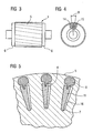
- FIG. 6 shows a sectional view of the rotor core 5 according to FIG. 4 with twisted short-circuit bars 12.
- the complete internal groove area 7 with the short-circuit bar 12 which is in particular is a twisted copper rod, filled.
- This high groove filling ensures the highest possible efficiency.
- a starting rod made of aluminum die cast material is realized. Due to the almost one-hundred percent groove filling in the radially inner groove region 7 with the copper rod, the aluminum diecasting material is almost exclusively located in the outer groove region 8, where it forms the high ohmic resistance of the short-circuit cage desired in the starting torque.
- FIG. 7 shows the straight shorting bar 11, which in the rotor core 5 according to FIG. 5 was introduced.
- FIG. 8 the already twisted shorting bar 12, with the according to FIG. 6 the greatest possible groove filling can be achieved.
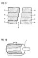
- FIG. 9 shows a section through a slanted Läufererblechvers comprising axially stacked electrical steel sheets 10.
- the electrical sheets 10 are in this case rotated against each other so that the desired groove bevel, for example, results in exactly one slot pitch.
- the rotor core can be made of the illustrated electrical sheets 10.
- the rotor laminations may be made by stacking the electrical laminations 10 on a filament mandrel having a tapered filament groove.
- FIG. 10 finally shows an asynchronous machine 2 with a squirrel cage according to an embodiment of the invention. Due to the hybrid construction of this asynchronous machine 2, which has a cage rotor made of copper rods, which are connected to each other at the front via aluminum die-cast rings, high efficiencies are achieved. Since the squirrel cage is designed slanted, the asynchronous machine has a very low harmonic content, is very quiet and is characterized by low torque ripple.
Priority Applications (6)
| Application Number | Priority Date | Filing Date | Title |
|---|---|---|---|
| EP09167044A EP2282396B1 (de) | 2009-08-03 | 2009-08-03 | Herstellungsverfahren für geschrägte Käfigläufer und geschrägter Käfigläufer |
| US13/388,412 US20120133236A1 (en) | 2009-08-03 | 2010-07-27 | Method for producing beveled cage rotor and beveled cage rotor |
| CN201080034580.6A CN102474163B (zh) | 2009-08-03 | 2010-07-27 | 斜槽式笼型转子的制造方法和斜槽式笼型转子 |
| RU2012108118/07A RU2548369C2 (ru) | 2009-08-03 | 2010-07-27 | Способ изготовления перекошенных короткозамкнутых роторов и перекошенный короткозамкнутый ротор |
| PCT/EP2010/060906 WO2011015494A1 (de) | 2009-08-03 | 2010-07-27 | Herstellungsverfahren für geschrägte käfigläufer und geschrägter käfigläufer |
| BR112012002606-2A BR112012002606B1 (pt) | 2009-08-03 | 2010-07-27 | Método para produzir um rotor em gaiola para uma máquina assíncrona, rotor em gaiola para uma máquina assíncrona e máquina assíncrona |
Applications Claiming Priority (1)
| Application Number | Priority Date | Filing Date | Title |
|---|---|---|---|
| EP09167044A EP2282396B1 (de) | 2009-08-03 | 2009-08-03 | Herstellungsverfahren für geschrägte Käfigläufer und geschrägter Käfigläufer |
Publications (2)
| Publication Number | Publication Date |
|---|---|
| EP2282396A1 EP2282396A1 (de) | 2011-02-09 |
| EP2282396B1 true EP2282396B1 (de) | 2012-12-05 |
Family
ID=41401689
Family Applications (1)
| Application Number | Title | Priority Date | Filing Date |
|---|---|---|---|
| EP09167044A Active EP2282396B1 (de) | 2009-08-03 | 2009-08-03 | Herstellungsverfahren für geschrägte Käfigläufer und geschrägter Käfigläufer |
Country Status (6)
| Country | Link |
|---|---|
| US (1) | US20120133236A1 (zh) |
| EP (1) | EP2282396B1 (zh) |
| CN (1) | CN102474163B (zh) |
| BR (1) | BR112012002606B1 (zh) |
| RU (1) | RU2548369C2 (zh) |
| WO (1) | WO2011015494A1 (zh) |
Cited By (1)
| Publication number | Priority date | Publication date | Assignee | Title |
|---|---|---|---|---|
| US11095172B2 (en) | 2016-08-05 | 2021-08-17 | Molabo Gmbh | Electric machine |
Families Citing this family (42)
| Publication number | Priority date | Publication date | Assignee | Title |
|---|---|---|---|---|
| DE102011078784A1 (de) | 2011-07-07 | 2013-01-10 | Siemens Ag | Elektrische Maschine mit Rotorinnenbelüftung |
| JP5562307B2 (ja) * | 2011-08-30 | 2014-07-30 | 日立オートモティブシステムズ株式会社 | かご形回転子および回転電機 |
| DE102011082353B4 (de) | 2011-09-08 | 2021-04-01 | Siemens Aktiengesellschaft | Stator für einen Elektromotor |
| DE102012203695A1 (de) | 2012-03-08 | 2013-09-12 | Siemens Aktiengesellschaft | Elektrische Maschine mit einer Zweikreiskühlung |
| DE102012203697A1 (de) | 2012-03-08 | 2013-09-12 | Siemens Aktiengesellschaft | Elektrische Maschine mit einem Rotor zur Kühlung der elektrischen Maschine |
| JP6013062B2 (ja) * | 2012-07-24 | 2016-10-25 | 株式会社日立製作所 | 誘導電動機およびこれを用いた鉄道車両 |
| DE102012213070A1 (de) | 2012-07-25 | 2014-01-30 | Siemens Aktiengesellschaft | Kühlmantel mit einem Dichtmittel |
| DE102012213059A1 (de) | 2012-07-25 | 2014-01-30 | Siemens Aktiengesellschaft | Kühlmantel |
| EP2744089A1 (de) | 2012-12-14 | 2014-06-18 | Siemens Aktiengesellschaft | Zuverlässiger Käfigläufer |
| JP5843980B2 (ja) * | 2012-12-26 | 2016-01-13 | 三菱電機株式会社 | かご形回転子の製造方法および誘導電動機の製造方法 |
| DE102013203937A1 (de) | 2013-03-07 | 2014-09-11 | Siemens Aktiengesellschaft | Elektrische Maschine ohne Resolver |
| CN105122595B (zh) | 2013-04-11 | 2019-07-05 | 西门子公司 | 磁阻电动机和附属的转子 |
| US10284032B2 (en) | 2013-04-12 | 2019-05-07 | Siemens Aktiengesellschaft | Reluctance rotor with runup aid |
| EP2928047A1 (de) | 2014-03-31 | 2015-10-07 | Siemens Aktiengesellschaft | Reluktanzrotor mit mechanischer Stabilisierung |
| DE102014210339A1 (de) | 2014-06-02 | 2015-12-03 | Siemens Aktiengesellschaft | Käfigläufer einer Asynchronmaschine |
| EP2961039B1 (de) | 2014-06-23 | 2019-10-02 | Siemens Aktiengesellschaft | Mechanisch stabilisierter Rotor für einen Reluktanzmotor |
| EP3070824A1 (de) | 2015-03-19 | 2016-09-21 | Siemens Aktiengesellschaft | Rotor einer synchronen Reluktanzmaschine |
| RU2677871C1 (ru) | 2015-07-17 | 2019-01-22 | Сименс Акциенгезелльшафт | Реактивный ротор с дополнительным собственным намагничиванием |
| EP3142228A1 (de) | 2015-09-10 | 2017-03-15 | Siemens Aktiengesellschaft | Stator für eine elektrische maschine, elektrische maschine sowie herstellungsverfahren |
| CN105356687B (zh) * | 2015-11-11 | 2017-10-03 | 成都中车电机有限公司 | 一种对牵引电动机鼠笼转子冲片无损伤的导条拆卸方法 |
| ES2667490T3 (es) | 2015-12-14 | 2018-05-11 | Siemens Aktiengesellschaft | Alineación de rotor para la reducción de las vibraciones y los ruidos |
| EP3193431A1 (de) | 2016-01-14 | 2017-07-19 | Siemens Aktiengesellschaft | Elektroblech mit gedrucktem steg |
| EP3252933A1 (de) | 2016-06-03 | 2017-12-06 | Siemens Aktiengesellschaft | Dynamoelektrische maschine mit einem thermosiphon |
| EP3258578A1 (de) | 2016-06-16 | 2017-12-20 | Siemens Aktiengesellschaft | Käfigläufer einer asynchronmaschine |
| DE102016225180A1 (de) * | 2016-12-15 | 2018-06-21 | Continental Automotive Gmbh | Elektrische Maschine |
| EP3402057A1 (de) * | 2017-05-09 | 2018-11-14 | Siemens Aktiengesellschaft | Verfahren zur herstellung eines kurzschlussläufers einer asynchronmaschine |
| FR3069731B1 (fr) | 2017-07-31 | 2021-12-24 | Leroy Somer Moteurs | Rotor a cage injectee |
| FR3069725B1 (fr) | 2017-07-31 | 2021-01-29 | Leroy Somer Moteurs | Rotor a cage injectee |
| FR3069735B1 (fr) | 2017-07-31 | 2023-01-20 | Leroy Somer Moteurs | Rotor a cage injectee |
| FR3069734B1 (fr) * | 2017-07-31 | 2022-12-30 | Leroy Somer Moteurs | Rotor a cage injectee |
| FR3069733B1 (fr) | 2017-07-31 | 2023-05-05 | Leroy Somer Moteurs | Rotor a cage injectee |
| FR3069727B1 (fr) | 2017-07-31 | 2021-02-12 | Leroy Somer Moteurs | Rotor a cage injectee |
| FR3069730B1 (fr) | 2017-07-31 | 2021-08-20 | Leroy Somer Moteurs | Rotor a cage injectee |
| FR3069732B1 (fr) | 2017-07-31 | 2021-02-12 | Leroy Somer Moteurs | Rotor a cage injectee |
| FR3069726B1 (fr) | 2017-07-31 | 2020-12-11 | Leroy Somer Moteurs | Rotor a cage injectee |
| CN107612167A (zh) * | 2017-09-28 | 2018-01-19 | 浙江兴轮电驱动有限公司 | 电机转子及电机 |
| EP3627661B1 (de) | 2018-09-21 | 2021-06-02 | Siemens Aktiengesellschaft | Käfigläufer und herstellung eines käfigläufers |
| CN111082608B (zh) * | 2019-11-26 | 2020-11-24 | 华北电力大学 | 一种高压大功率笼型电机转子铜条消谐槽加工方法 |
| CN110932430A (zh) * | 2019-12-17 | 2020-03-27 | 安徽艾格赛特电机科技有限公司 | 一种插铜铸铝混合结构的转子及其制造方法 |
| DE102020116383A1 (de) | 2020-06-22 | 2021-12-23 | Valeo Siemens Eautomotive Germany Gmbh | Verfahren zur Herstellung eines geschrägten Stators |
| DE102020121380A1 (de) | 2020-08-14 | 2022-02-17 | Dr. Ing. H.C. F. Porsche Aktiengesellschaft | Stator für eine elektrische Maschine, Verfahren zu seiner Herstellung, elektrische Maschine und Kraftfahrzeug |
| CN113241918A (zh) * | 2021-05-21 | 2021-08-10 | 博能传动(苏州)有限公司 | 一种嵌铜铸铝结构转子 |
Family Cites Families (12)
| Publication number | Priority date | Publication date | Assignee | Title |
|---|---|---|---|---|
| DE4308683A1 (de) | 1993-03-18 | 1994-09-22 | Siemens Ag | Käfigläufer für eine Asynchronmaschine |
| JPH08149768A (ja) * | 1994-11-25 | 1996-06-07 | Hitachi Ltd | 誘導電動機のダイカスト回転子 |
| JPH08223878A (ja) * | 1995-02-09 | 1996-08-30 | Hitachi Ltd | 誘導電動機 |
| JPH1028360A (ja) * | 1996-07-11 | 1998-01-27 | Hitachi Ltd | 誘導電動機およびその回転子 |
| KR100201857B1 (ko) * | 1996-12-03 | 1999-06-15 | 윤종용 | 농형회전자 |
| JPH10234166A (ja) * | 1997-02-19 | 1998-09-02 | Hitachi Ltd | 誘導電動機の回転子 |
| RU2127016C1 (ru) * | 1998-06-09 | 1999-02-27 | Селиванов Николай Павлович | Способ изготовления асинхронного электродвигателя и асинхронный электродвигатель с короткозамкнутым ротором |
| RU2130681C1 (ru) * | 1998-06-09 | 1999-05-20 | Селиванов Николай Павлович | Способ изготовления асинхронного электродвигателя и асинхронный электродвигатель с короткозамкнутым ротором |
| EP1139549A3 (en) * | 2000-03-29 | 2002-06-05 | SANYO ELECTRIC Co., Ltd. | Sealed motor compressor |
| US6998752B2 (en) * | 2000-12-27 | 2006-02-14 | Hitachi, Ltd. | Dynamo-electric machine |
| JP2005278373A (ja) * | 2004-03-26 | 2005-10-06 | Jatco Ltd | 誘導電動機の回転子 |
| JP5019451B2 (ja) * | 2007-11-15 | 2012-09-05 | 東芝産業機器製造株式会社 | 回転子 |
-
2009
- 2009-08-03 EP EP09167044A patent/EP2282396B1/de active Active
-
2010
- 2010-07-27 RU RU2012108118/07A patent/RU2548369C2/ru not_active IP Right Cessation
- 2010-07-27 US US13/388,412 patent/US20120133236A1/en not_active Abandoned
- 2010-07-27 BR BR112012002606-2A patent/BR112012002606B1/pt active IP Right Grant
- 2010-07-27 CN CN201080034580.6A patent/CN102474163B/zh active Active
- 2010-07-27 WO PCT/EP2010/060906 patent/WO2011015494A1/de active Application Filing
Cited By (1)
| Publication number | Priority date | Publication date | Assignee | Title |
|---|---|---|---|---|
| US11095172B2 (en) | 2016-08-05 | 2021-08-17 | Molabo Gmbh | Electric machine |
Also Published As
| Publication number | Publication date |
|---|---|
| CN102474163A (zh) | 2012-05-23 |
| EP2282396A1 (de) | 2011-02-09 |
| WO2011015494A1 (de) | 2011-02-10 |
| RU2012108118A (ru) | 2013-09-10 |
| CN102474163B (zh) | 2014-10-29 |
| US20120133236A1 (en) | 2012-05-31 |
| BR112012002606B1 (pt) | 2019-10-15 |
| RU2548369C2 (ru) | 2015-04-20 |
| BR112012002606A2 (pt) | 2016-03-22 |
Similar Documents
| Publication | Publication Date | Title |
|---|---|---|
| EP2282396B1 (de) | Herstellungsverfahren für geschrägte Käfigläufer und geschrägter Käfigläufer | |
| EP3178155B1 (de) | Rotor, reluktanzmaschine und herstellungsverfahren für rotor | |
| EP2288004B1 (de) | Käfigläufer mit Anlaufstab | |
| EP2299565B1 (de) | Kühlung eines Asynchronläufers | |
| EP3178152B1 (de) | Rotor und reluktanzmaschine | |
| EP2891234B1 (de) | Käfigläufer und stab mit einem einschnitt | |
| DE19542962C1 (de) | Kurzschlußläufer für eine Asynchronmaschine und ein Verfahren zur Herstellung desselben | |
| EP2891233B1 (de) | Käfigläufer mit deformierbarer lagerung | |
| WO2020020787A1 (de) | Rotor, elektromotor, verfahren zur herstellung eines rotors sowie verwendung eines rotors bzw. elektromotors | |
| EP2885858B1 (de) | Käfigrotor für eine elektrische maschine | |
| EP2149970B1 (de) | Rotor für Asynchronmaschinen | |
| DE102005030797A1 (de) | Käfigläufer einer Induktionsmaschine | |
| DE102009051488A1 (de) | Käfigläufer mit funktionaler Läufernut | |
| EP3145059A1 (de) | Käfigläufer | |
| DE102008015327B4 (de) | Rotor einer elektrischen Maschine und Motor mit einem derartigen Rotor | |
| EP1883150A2 (de) | Läufer einer elektrischen Asynchronmaschine | |
| WO2023217783A1 (de) | Rotor eines käfigläufer-motors und verfahren zu seiner herstellung | |
| DE102020212636A1 (de) | Rotor für eine elektrische Maschine, elektrische Maschine und Kraftfahrzeug | |
| WO2017029216A1 (de) | Rotorpaket für eine synchronreluktanzmaschine | |
| DE102019123552A1 (de) | Verfahren zur Herstellung eines Rotors, Rotor sowie Asynchronmotor | |
| EP3706288A1 (de) | Blechpaket für eine elektrische maschine | |
| EP3425778A1 (de) | Verfahren zur herstellung eines kurzschlussringes aus einem metallband | |
| DE10247483A1 (de) | Elektrische Maschine | |
| EP3133719A1 (de) | Rotor einer synchronen reluktanzmaschine | |
| AT508881A1 (de) | Rotor für asynchronmaschinen |
Legal Events
| Date | Code | Title | Description |
|---|---|---|---|
| PUAI | Public reference made under article 153(3) epc to a published international application that has entered the european phase |
Free format text: ORIGINAL CODE: 0009012 |
|
| AK | Designated contracting states |
Kind code of ref document: A1 Designated state(s): AT BE BG CH CY CZ DE DK EE ES FI FR GB GR HR HU IE IS IT LI LT LU LV MC MK MT NL NO PL PT RO SE SI SK SM TR |
|
| AX | Request for extension of the european patent |
Extension state: AL BA RS |
|
| 17P | Request for examination filed |
Effective date: 20110808 |
|
| 17Q | First examination report despatched |
Effective date: 20110905 |
|
| GRAP | Despatch of communication of intention to grant a patent |
Free format text: ORIGINAL CODE: EPIDOSNIGR1 |
|
| GRAC | Information related to communication of intention to grant a patent modified |
Free format text: ORIGINAL CODE: EPIDOSCIGR1 |
|
| GRAC | Information related to communication of intention to grant a patent modified |
Free format text: ORIGINAL CODE: EPIDOSCIGR1 |
|
| GRAS | Grant fee paid |
Free format text: ORIGINAL CODE: EPIDOSNIGR3 |
|
| GRAA | (expected) grant |
Free format text: ORIGINAL CODE: 0009210 |
|
| AK | Designated contracting states |
Kind code of ref document: B1 Designated state(s): AT BE BG CH CY CZ DE DK EE ES FI FR GB GR HR HU IE IS IT LI LT LU LV MC MK MT NL NO PL PT RO SE SI SK SM TR |
|
| REG | Reference to a national code |
Ref country code: GB Ref legal event code: FG4D Free format text: NOT ENGLISH |
|
| REG | Reference to a national code |
Ref country code: CH Ref legal event code: EP |
|
| REG | Reference to a national code |
Ref country code: AT Ref legal event code: REF Ref document number: 587731 Country of ref document: AT Kind code of ref document: T Effective date: 20121215 |
|
| REG | Reference to a national code |
Ref country code: IE Ref legal event code: FG4D Free format text: LANGUAGE OF EP DOCUMENT: GERMAN |
|
| REG | Reference to a national code |
Ref country code: DE Ref legal event code: R096 Ref document number: 502009005560 Country of ref document: DE Effective date: 20130131 |
|
| RAP2 | Party data changed (patent owner data changed or rights of a patent transferred) |
Owner name: SIEMENS AKTIENGESELLSCHAFT |
|
| PG25 | Lapsed in a contracting state [announced via postgrant information from national office to epo] |
Ref country code: NO Free format text: LAPSE BECAUSE OF FAILURE TO SUBMIT A TRANSLATION OF THE DESCRIPTION OR TO PAY THE FEE WITHIN THE PRESCRIBED TIME-LIMIT Effective date: 20130305 Ref country code: SE Free format text: LAPSE BECAUSE OF FAILURE TO SUBMIT A TRANSLATION OF THE DESCRIPTION OR TO PAY THE FEE WITHIN THE PRESCRIBED TIME-LIMIT Effective date: 20121205 Ref country code: FI Free format text: LAPSE BECAUSE OF FAILURE TO SUBMIT A TRANSLATION OF THE DESCRIPTION OR TO PAY THE FEE WITHIN THE PRESCRIBED TIME-LIMIT Effective date: 20121205 Ref country code: LT Free format text: LAPSE BECAUSE OF FAILURE TO SUBMIT A TRANSLATION OF THE DESCRIPTION OR TO PAY THE FEE WITHIN THE PRESCRIBED TIME-LIMIT Effective date: 20121205 Ref country code: HR Free format text: LAPSE BECAUSE OF FAILURE TO SUBMIT A TRANSLATION OF THE DESCRIPTION OR TO PAY THE FEE WITHIN THE PRESCRIBED TIME-LIMIT Effective date: 20121205 Ref country code: ES Free format text: LAPSE BECAUSE OF FAILURE TO SUBMIT A TRANSLATION OF THE DESCRIPTION OR TO PAY THE FEE WITHIN THE PRESCRIBED TIME-LIMIT Effective date: 20130316 |
|
| REG | Reference to a national code |
Ref country code: NL Ref legal event code: VDEP Effective date: 20121205 |
|
| REG | Reference to a national code |
Ref country code: LT Ref legal event code: MG4D |
|
| PG25 | Lapsed in a contracting state [announced via postgrant information from national office to epo] |
Ref country code: GR Free format text: LAPSE BECAUSE OF FAILURE TO SUBMIT A TRANSLATION OF THE DESCRIPTION OR TO PAY THE FEE WITHIN THE PRESCRIBED TIME-LIMIT Effective date: 20130306 Ref country code: PL Free format text: LAPSE BECAUSE OF FAILURE TO SUBMIT A TRANSLATION OF THE DESCRIPTION OR TO PAY THE FEE WITHIN THE PRESCRIBED TIME-LIMIT Effective date: 20121205 Ref country code: LV Free format text: LAPSE BECAUSE OF FAILURE TO SUBMIT A TRANSLATION OF THE DESCRIPTION OR TO PAY THE FEE WITHIN THE PRESCRIBED TIME-LIMIT Effective date: 20121205 Ref country code: SI Free format text: LAPSE BECAUSE OF FAILURE TO SUBMIT A TRANSLATION OF THE DESCRIPTION OR TO PAY THE FEE WITHIN THE PRESCRIBED TIME-LIMIT Effective date: 20121205 |
|
| PG25 | Lapsed in a contracting state [announced via postgrant information from national office to epo] |
Ref country code: EE Free format text: LAPSE BECAUSE OF FAILURE TO SUBMIT A TRANSLATION OF THE DESCRIPTION OR TO PAY THE FEE WITHIN THE PRESCRIBED TIME-LIMIT Effective date: 20121205 Ref country code: IS Free format text: LAPSE BECAUSE OF FAILURE TO SUBMIT A TRANSLATION OF THE DESCRIPTION OR TO PAY THE FEE WITHIN THE PRESCRIBED TIME-LIMIT Effective date: 20130405 Ref country code: SK Free format text: LAPSE BECAUSE OF FAILURE TO SUBMIT A TRANSLATION OF THE DESCRIPTION OR TO PAY THE FEE WITHIN THE PRESCRIBED TIME-LIMIT Effective date: 20121205 Ref country code: BG Free format text: LAPSE BECAUSE OF FAILURE TO SUBMIT A TRANSLATION OF THE DESCRIPTION OR TO PAY THE FEE WITHIN THE PRESCRIBED TIME-LIMIT Effective date: 20130305 Ref country code: CZ Free format text: LAPSE BECAUSE OF FAILURE TO SUBMIT A TRANSLATION OF THE DESCRIPTION OR TO PAY THE FEE WITHIN THE PRESCRIBED TIME-LIMIT Effective date: 20121205 |
|
| PG25 | Lapsed in a contracting state [announced via postgrant information from national office to epo] |
Ref country code: PT Free format text: LAPSE BECAUSE OF FAILURE TO SUBMIT A TRANSLATION OF THE DESCRIPTION OR TO PAY THE FEE WITHIN THE PRESCRIBED TIME-LIMIT Effective date: 20130405 Ref country code: NL Free format text: LAPSE BECAUSE OF FAILURE TO SUBMIT A TRANSLATION OF THE DESCRIPTION OR TO PAY THE FEE WITHIN THE PRESCRIBED TIME-LIMIT Effective date: 20121205 Ref country code: RO Free format text: LAPSE BECAUSE OF FAILURE TO SUBMIT A TRANSLATION OF THE DESCRIPTION OR TO PAY THE FEE WITHIN THE PRESCRIBED TIME-LIMIT Effective date: 20121205 |
|
| PLBE | No opposition filed within time limit |
Free format text: ORIGINAL CODE: 0009261 |
|
| STAA | Information on the status of an ep patent application or granted ep patent |
Free format text: STATUS: NO OPPOSITION FILED WITHIN TIME LIMIT |
|
| PG25 | Lapsed in a contracting state [announced via postgrant information from national office to epo] |
Ref country code: DK Free format text: LAPSE BECAUSE OF FAILURE TO SUBMIT A TRANSLATION OF THE DESCRIPTION OR TO PAY THE FEE WITHIN THE PRESCRIBED TIME-LIMIT Effective date: 20121205 |
|
| 26N | No opposition filed |
Effective date: 20130906 |
|
| PG25 | Lapsed in a contracting state [announced via postgrant information from national office to epo] |
Ref country code: CY Free format text: LAPSE BECAUSE OF FAILURE TO SUBMIT A TRANSLATION OF THE DESCRIPTION OR TO PAY THE FEE WITHIN THE PRESCRIBED TIME-LIMIT Effective date: 20121205 |
|
| PG25 | Lapsed in a contracting state [announced via postgrant information from national office to epo] |
Ref country code: IT Free format text: LAPSE BECAUSE OF FAILURE TO SUBMIT A TRANSLATION OF THE DESCRIPTION OR TO PAY THE FEE WITHIN THE PRESCRIBED TIME-LIMIT Effective date: 20121205 |
|
| REG | Reference to a national code |
Ref country code: DE Ref legal event code: R097 Ref document number: 502009005560 Country of ref document: DE Effective date: 20130906 |
|
| BERE | Be: lapsed |
Owner name: SIEMENS A.G. Effective date: 20130831 |
|
| REG | Reference to a national code |
Ref country code: CH Ref legal event code: PL |
|
| GBPC | Gb: european patent ceased through non-payment of renewal fee |
Effective date: 20130803 |
|
| PG25 | Lapsed in a contracting state [announced via postgrant information from national office to epo] |
Ref country code: LI Free format text: LAPSE BECAUSE OF NON-PAYMENT OF DUE FEES Effective date: 20130831 Ref country code: MC Free format text: LAPSE BECAUSE OF FAILURE TO SUBMIT A TRANSLATION OF THE DESCRIPTION OR TO PAY THE FEE WITHIN THE PRESCRIBED TIME-LIMIT Effective date: 20121205 Ref country code: CH Free format text: LAPSE BECAUSE OF NON-PAYMENT OF DUE FEES Effective date: 20130831 |
|
| REG | Reference to a national code |
Ref country code: IE Ref legal event code: MM4A |
|
| PG25 | Lapsed in a contracting state [announced via postgrant information from national office to epo] |
Ref country code: BE Free format text: LAPSE BECAUSE OF NON-PAYMENT OF DUE FEES Effective date: 20130831 |
|
| PG25 | Lapsed in a contracting state [announced via postgrant information from national office to epo] |
Ref country code: GB Free format text: LAPSE BECAUSE OF NON-PAYMENT OF DUE FEES Effective date: 20130803 Ref country code: IE Free format text: LAPSE BECAUSE OF NON-PAYMENT OF DUE FEES Effective date: 20130803 |
|
| PG25 | Lapsed in a contracting state [announced via postgrant information from national office to epo] |
Ref country code: SM Free format text: LAPSE BECAUSE OF FAILURE TO SUBMIT A TRANSLATION OF THE DESCRIPTION OR TO PAY THE FEE WITHIN THE PRESCRIBED TIME-LIMIT Effective date: 20121205 |
|
| PG25 | Lapsed in a contracting state [announced via postgrant information from national office to epo] |
Ref country code: TR Free format text: LAPSE BECAUSE OF FAILURE TO SUBMIT A TRANSLATION OF THE DESCRIPTION OR TO PAY THE FEE WITHIN THE PRESCRIBED TIME-LIMIT Effective date: 20121205 Ref country code: MT Free format text: LAPSE BECAUSE OF FAILURE TO SUBMIT A TRANSLATION OF THE DESCRIPTION OR TO PAY THE FEE WITHIN THE PRESCRIBED TIME-LIMIT Effective date: 20121205 |
|
| PG25 | Lapsed in a contracting state [announced via postgrant information from national office to epo] |
Ref country code: HU Free format text: LAPSE BECAUSE OF FAILURE TO SUBMIT A TRANSLATION OF THE DESCRIPTION OR TO PAY THE FEE WITHIN THE PRESCRIBED TIME-LIMIT; INVALID AB INITIO Effective date: 20090803 Ref country code: MK Free format text: LAPSE BECAUSE OF FAILURE TO SUBMIT A TRANSLATION OF THE DESCRIPTION OR TO PAY THE FEE WITHIN THE PRESCRIBED TIME-LIMIT Effective date: 20121205 Ref country code: LU Free format text: LAPSE BECAUSE OF NON-PAYMENT OF DUE FEES Effective date: 20130803 |
|
| REG | Reference to a national code |
Ref country code: AT Ref legal event code: MM01 Ref document number: 587731 Country of ref document: AT Kind code of ref document: T Effective date: 20140803 |
|
| PG25 | Lapsed in a contracting state [announced via postgrant information from national office to epo] |
Ref country code: AT Free format text: LAPSE BECAUSE OF NON-PAYMENT OF DUE FEES Effective date: 20140803 |
|
| REG | Reference to a national code |
Ref country code: FR Ref legal event code: PLFP Year of fee payment: 8 |
|
| REG | Reference to a national code |
Ref country code: FR Ref legal event code: PLFP Year of fee payment: 9 |
|
| REG | Reference to a national code |
Ref country code: FR Ref legal event code: PLFP Year of fee payment: 10 |
|
| PGFP | Annual fee paid to national office [announced via postgrant information from national office to epo] |
Ref country code: FR Payment date: 20230822 Year of fee payment: 15 |
|
| PGFP | Annual fee paid to national office [announced via postgrant information from national office to epo] |
Ref country code: DE Payment date: 20231019 Year of fee payment: 15 |