EP2281294B1 - Hochspannungs-messwandler mit flexibler isolierung - Google Patents
Hochspannungs-messwandler mit flexibler isolierung Download PDFInfo
- Publication number
- EP2281294B1 EP2281294B1 EP09757030A EP09757030A EP2281294B1 EP 2281294 B1 EP2281294 B1 EP 2281294B1 EP 09757030 A EP09757030 A EP 09757030A EP 09757030 A EP09757030 A EP 09757030A EP 2281294 B1 EP2281294 B1 EP 2281294B1
- Authority
- EP
- European Patent Office
- Prior art keywords
- insulation
- high voltage
- voltage transducer
- compressible
- flexible
- Prior art date
- Legal status (The legal status is an assumption and is not a legal conclusion. Google has not performed a legal analysis and makes no representation as to the accuracy of the status listed.)
- Active
Links
Images



Classifications
-
- H—ELECTRICITY
- H01—ELECTRIC ELEMENTS
- H01F—MAGNETS; INDUCTANCES; TRANSFORMERS; SELECTION OF MATERIALS FOR THEIR MAGNETIC PROPERTIES
- H01F38/00—Adaptations of transformers or inductances for specific applications or functions
- H01F38/20—Instruments transformers
-
- H—ELECTRICITY
- H01—ELECTRIC ELEMENTS
- H01B—CABLES; CONDUCTORS; INSULATORS; SELECTION OF MATERIALS FOR THEIR CONDUCTIVE, INSULATING OR DIELECTRIC PROPERTIES
- H01B3/00—Insulators or insulating bodies characterised by the insulating materials; Selection of materials for their insulating or dielectric properties
- H01B3/18—Insulators or insulating bodies characterised by the insulating materials; Selection of materials for their insulating or dielectric properties mainly consisting of organic substances
- H01B3/30—Insulators or insulating bodies characterised by the insulating materials; Selection of materials for their insulating or dielectric properties mainly consisting of organic substances plastics; resins; waxes
- H01B3/46—Insulators or insulating bodies characterised by the insulating materials; Selection of materials for their insulating or dielectric properties mainly consisting of organic substances plastics; resins; waxes silicones
-
- H—ELECTRICITY
- H01—ELECTRIC ELEMENTS
- H01F—MAGNETS; INDUCTANCES; TRANSFORMERS; SELECTION OF MATERIALS FOR THEIR MAGNETIC PROPERTIES
- H01F27/00—Details of transformers or inductances, in general
- H01F27/02—Casings
- H01F27/022—Encapsulation
-
- H—ELECTRICITY
- H01—ELECTRIC ELEMENTS
- H01F—MAGNETS; INDUCTANCES; TRANSFORMERS; SELECTION OF MATERIALS FOR THEIR MAGNETIC PROPERTIES
- H01F41/00—Apparatus or processes specially adapted for manufacturing or assembling magnets, inductances or transformers; Apparatus or processes specially adapted for manufacturing materials characterised by their magnetic properties
- H01F41/005—Impregnating or encapsulating
-
- H—ELECTRICITY
- H01—ELECTRIC ELEMENTS
- H01F—MAGNETS; INDUCTANCES; TRANSFORMERS; SELECTION OF MATERIALS FOR THEIR MAGNETIC PROPERTIES
- H01F27/00—Details of transformers or inductances, in general
- H01F27/28—Coils; Windings; Conductive connections
- H01F27/32—Insulating of coils, windings, or parts thereof
- H01F27/327—Encapsulating or impregnating
-
- H—ELECTRICITY
- H01—ELECTRIC ELEMENTS
- H01F—MAGNETS; INDUCTANCES; TRANSFORMERS; SELECTION OF MATERIALS FOR THEIR MAGNETIC PROPERTIES
- H01F38/00—Adaptations of transformers or inductances for specific applications or functions
- H01F38/20—Instruments transformers
- H01F38/22—Instruments transformers for single phase AC
- H01F38/24—Voltage transformers
- H01F38/26—Constructions
-
- H—ELECTRICITY
- H01—ELECTRIC ELEMENTS
- H01F—MAGNETS; INDUCTANCES; TRANSFORMERS; SELECTION OF MATERIALS FOR THEIR MAGNETIC PROPERTIES
- H01F38/00—Adaptations of transformers or inductances for specific applications or functions
- H01F38/20—Instruments transformers
- H01F38/22—Instruments transformers for single phase AC
- H01F38/28—Current transformers
- H01F38/30—Constructions
-
- H—ELECTRICITY
- H01—ELECTRIC ELEMENTS
- H01F—MAGNETS; INDUCTANCES; TRANSFORMERS; SELECTION OF MATERIALS FOR THEIR MAGNETIC PROPERTIES
- H01F41/00—Apparatus or processes specially adapted for manufacturing or assembling magnets, inductances or transformers; Apparatus or processes specially adapted for manufacturing materials characterised by their magnetic properties
- H01F41/02—Apparatus or processes specially adapted for manufacturing or assembling magnets, inductances or transformers; Apparatus or processes specially adapted for manufacturing materials characterised by their magnetic properties for manufacturing cores, coils, or magnets
- H01F41/04—Apparatus or processes specially adapted for manufacturing or assembling magnets, inductances or transformers; Apparatus or processes specially adapted for manufacturing materials characterised by their magnetic properties for manufacturing cores, coils, or magnets for manufacturing coils
- H01F41/12—Insulating of windings
- H01F41/127—Encapsulating or impregnating
Definitions
- the invention relates to a high-voltage transducer with an insulation.
- the high-voltage transducers are installed in networks to measure voltages and currents for the following tasks: power measurement, grid monitoring in terms of disturbances, load flow control in the networks, optimization or minimization of losses in the networks, etc.
- US 3,525,908 discloses a high voltage transducer according to the preamble of claim 1.
- SF 6 insulation mentioned in point 3 above is more problematic for outdoor converters, as SF 6 can escape into the atmosphere if a shell or a sealing system of the outdoor converter is damaged.
- a pressure gauge of the necessary gas pressure is little used, as experience has shown that used measuring instruments represent a weak point. Switchgear systems with SF 6 insulation are to be judged much more favorably, since they are constantly monitored, and strict legal conditions must be met.
- High-voltage transducers equipped with oil paper and SF 6 insulation are labor-intensive to manufacture. In order to produce more cost-effectively, these labor-intensive insulation should be replaced by a more cost-effective insulation.
- a high voltage transducer is in Fig. 1 in section, a measuring part of a high-voltage current transformer according to the prior art with an oil-paper insulation 512 shown.
- the high voltage current transformer comprises a metal housing (head) 501 which is at high voltage potential 516.
- the high voltage current transformer comprises a conductor 502 which carries a current I p to be measured and how the housing 501 is at high voltage potential 516.
- measuring cores 504 are installed for the detection of the current I p .
- a gap 505 between the oil-paper insulation 512 and the housing 501 is filled with oil.
- a bushing 506 (controlled insulation) comprises a metallic support tube 507 at ground potential 508 and any insulator 509, e.g. Oil-based paper (OIP), resin-impregnated crepe paper (RIP), kraft paper (RBP), films with a suitable impregnating agent such as SF 6 , air or oil.
- An insulator 510 is the necessary insulator between the housing at high voltage potential 516 and ground.
- a compensating bellows 511 is necessary for oil-paper insulation and compensates for a temperature-related volume change of the oil.
- a high-voltage voltage converter according to the prior art is shown as another example of a high-voltage transducer.
- the high voltage voltage converter comprises a housing 523b, which is at ground potential 528, a trapezoidal layer winding 531 with insulation, a bushing 526, an insulator 529 and an iron core 524.
- a high voltage electrode 521 on high voltage potential 536 and a ground electrode 523a at ground potential 528 and the housing 523b (ground potential 528) an oil-paper insulation 532 is used.
- Below ground electrode 523a is a secondary winding 535 arranged.
- the high-voltage voltage converter comprises as a voltage connection 522 a metal tube 527 in the bushing 526 with an active part, the voltage connection 522 being connected to the high-voltage electrode 521.
- the trapezoidal layer winding 531 is connected to the high voltage electrode 521 and the ground electrode 523a (ground potential 528).
- the high voltage voltage converter comprises an oil gap 525, analogous to the gap 505 (see Fig. 1 ).
- the oil-paper insulation comprises a ply insulation between the trapezoidal ply wrap 531 and a final-distance insulation 533.
- the end-distance insulation 533 is disposed between a ply winding end 534 and the housing 523b at ground potential 528.
- the present invention has for its object to provide a high-voltage transducer, which does not have the disadvantages associated with an oil or SF 6 insulation, can also be used at high voltages and can be produced inexpensively.
- the independent claim 10 relates to a method for producing a high-voltage transducer according to the invention. Vorheilhafte embodiments emerge from the dependent claims.
- a high-voltage transducer according to the invention has an insulation comprising a flexible and compressible silicone gel insulation.
- Compressible insulation allows use existing converter designs for widely varying temperature ranges.
- the silicone gel insulation is an excellent insulation that is dry and flexible and will not cause environmental damage if damaged.
- the high-voltage transducer according to the invention is a current transformer with a head insulation against ground for the measurement of a current in a switchgear, wherein the insulation between high voltage and ground comprises the flexible and compressible silicone gel insulation. This eliminates the need for an oil compensation bellows required in the prior art.
- the high-voltage transducer is an inductive voltage transformer for measuring a primary voltage U p between phase and earth or between phase and neutral in single-, two- and three-phase systems, with a primary winding and one or more secondary windings, the insulation between layer winding and housing includes flexible and compressible silicone gel insulation.
- the flexible and compressible silicone gel insulation of the inventive high voltage transducer has at least one resin and a hardener, e.g. B. WACKER SilGel® 612.
- a hardener e.g. B. WACKER SilGel® 612.
- the outstanding properties of two-component (epoxy and polyurethane resin) resins lead to insulation that has a very low viscosity in the unpolymerized state and is easily degassed and shed. These properties and a sum of trials and considerations led to the selection of a two component silicone gel casting resin.
- the WACKER SilGel® 612 is a pourable, room temperature addition-curing two-component silicone insulation. It does not vulcanize to a silicone rubber in the conventional sense, but gives a soft gel-like insulation.
- WACKER SilGel® 612 will be delivered without any free silicone fluids.
- the cross-linked silicone gel is soft and flexible. It has a high dielectric strength, which corresponds to the operating field strengths of the prior art oil paper insulation.
- the insulation produced with the silicone gel used can be used in the following temperature ranges, which are typically required for high-voltage transducers: outside temperature of -50 ° C to + 60 ° C or operating temperature of the insulation due to the self-heating of the high-voltage transducer of -50 ° C to + 100 ° C.
- the flexible and compressible silicone gel insulation of the high-voltage transducer according to the invention has a compressible filler.
- a filler of compressible hollow microspheres was determined by experiments using gas, e.g. B. with pentane or isobutane, are filled.
- gas e.g. B. with pentane or isobutane
- Various fill levels eg 10%, 30%, 50%
- compression tests were carried out to achieve the required compressibility.
- Different hollow microspheres with different spherical size, coating, material and filling gas were tested as filler. Dielectric tests with ball-and-ball arrangement and plate-plate arrangement (criterion 1% of the breakdown field strength) were made.
- the resulting hollow microspheres have a diameter in the range of 10 microns to 80 microns, preferably from 20 microns to 30 microns.
- the hollow microspheres have a wall thickness of 1.5 microns to 2.5 microns.
- the size of the spheres resulted from a compromise on the partial discharge freedom of the cured crosslinked bicomponent insulating resin, price, miscibility and electrical requirements determined by experimental breakdown tests. Also, the filler adds to the breakdown field strength and field strength without shortening the life. All of this is done incorporating requirements for treating a casting surface of an inner core shell and an inner header housing wall for high electrical field strengths.
- the compressible filler comprises hollow microspheres.
- the hollow microspheres are z. B. the type Expancel 091 DE40d30 the company Expancel.
- the said hollow microspheres have proven to be particularly advantageous, but another filler is quite conceivable.
- the proportion of hollow microspheres is 20% to 50%, preferably 30% to 40%.
- the hollow microspheres each have a thermoplastic shell which is provided with a size for bonding the hollow microspheres to the silicone gel.
- the hollow microspheres are inside with a gas, eg. For example, isobutane or pentane, filled.
- the sizing has the function of a primer on the hollow microsphere so that the silicone gel can adhere well.
- the flexible and compressible silicone gel insulation between -50 ° C and + 60 ° C ambient temperature is compressible by 15% to 30% in the inventive high-voltage transducer.
- the necessary compressibility depends on the size of the converter housing. Due to the compressibility of the necessary in the prior art ⁇ lkompensationsbalg omitted.
- Another aspect of the present invention relates to a method of making a high voltage transducer in accordance with the present invention having flexible and compressible silicone gel insulation comprising a resin, a hardener, and a filler, wherein the resin comprises filler and the hardener contains filler be premixed separately under vacuum.
- resin, hardener and filler are mixed with a mixer under vacuum, then filled into a housing under vacuum and finally pressurized. After filling, the vacuum is broken and the silicone gel insulation at 20 ° C by 15% until 30% compressed. The filling allows a minimization of the work required for the production of the insulation.
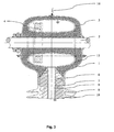
- a first embodiment of a high-voltage current transformer according to the invention is shown as a high-voltage transducer with a flexible and compressible silicone gel insulation 13, which in comparison to the prior art, the oil-paper insulation 512 (see Fig. 1 ) replaced.
- the high-voltage current transformer comprises a housing (head) 1 made of metal, which is at high voltage potential 16. Also, the high-voltage current transformer comprises a conductor 2, which leads a current I p to be measured and how the housing 1 is at high-voltage potential 16.
- measuring cores 4 are installed for the detection of the current I p .
- a bushing 6 or controlled insulation comprises a metallic support tube 7 at ground potential 8 and any insulating material 9, z. B.
- oil-paper OIP
- resin impregnated Crepe paper RIP
- kraft paper RBP
- films with a suitable impregnating agent such as SF 6 , air or oil.
- An insulator 10 is the necessary insulator between the housing at high voltage potential 16 and ground.
- An oil expansion component see compensating bellows 511 in Fig. 1 ), which is necessary for oil-paper insulation and compensates for a temperature-related expansion of the oil, is not needed.
- a section through a second embodiment of a high voltage voltage converter according to the invention as a high voltage transducer with a flexible and compressible silicone gel insulation 36 is shown, which in comparison to the prior art, the end distance insulation 533 (see Fig. 2 ) and the oil slit 525 (see Fig. 2 ) replaced.
- the high voltage voltage converter comprises a housing 23b, which is at ground potential 28, a high voltage electrode 21 at high voltage potential 26, an earth electrode 23a and an iron core 24. Below the earth electrode 23a, a secondary winding 35 is arranged.
- the high-voltage voltage converter comprises as a voltage connection a metal tube 27 in a passage with an active part 29, wherein the voltage terminal is connected to the high-voltage electrode 21.
- a trapezoidal layer winding 31 as a primary winding with layer windings and a layer winding end 34 are connected to the high voltage electrode 21 and the ground potential 28.
- the insulation between the ply windings must continue to exist for the construction of the trapezoidal ply winding 31.
- the insulation between the ply windings must be compatible with the silicone gel insulation, and the silicone gel insulation must adhere very well to the ply windings so that it can can not form columns that lead to partial discharges.
Landscapes
- Engineering & Computer Science (AREA)
- Power Engineering (AREA)
- Manufacturing & Machinery (AREA)
- Physics & Mathematics (AREA)
- Spectroscopy & Molecular Physics (AREA)
- Organic Insulating Materials (AREA)
- Transformers For Measuring Instruments (AREA)
- Transducers For Ultrasonic Waves (AREA)
- Measuring Fluid Pressure (AREA)
- Ultra Sonic Daignosis Equipment (AREA)
- Insulating Of Coils (AREA)
Description
- Die Erfindung betrifft einen Hochspannungs-Messwandler mit einer Isolierung.
- Die Hochspannungs-Messwandler werden in Netze eingebaut, um Spannungen und Ströme für folgende Aufgaben zu messen: Leistungsmessung, Netzüberwachung in Bezug auf Störungen, Lastflussregelung in den Netzen, Optimierung bzw. Minimierung der Verluste in den Netzen, etc.
-
US 3 525 908 offenbart einen Hochspannungs-Messwandler gemäß Oberbegriff des Anspruchs 1. - Stand der Technik sind folgende Hochspannungs-Messwandler mit Isolierungen für einen Spannungsbereich von 6 kV bis 800 kV Wechsel- oder Gleichspannung:
- 1. Epoxydharz oder Polyurethanharz Feststoff-Isolierungen im Bereich von 6 kV bis 100 kV für Innenraum- und Freiluftschaltanlagen.
- 2. Ölpapier-Isolierungen für den Bereich von 72.5 kV bis 800 kV und höher.
- 3. SF6-Isolierungen für den Bereich von 72.5 kV bis 800 kV und höher.
- Die vorstehend unter Punkt 2 und Punkt 3 genannten Isolierungen haben aus der Sicht der Umweltverträglichkeit gewisse Nachteile: Bei Beschädigung einer Hülle der Isolierung der unter Punkt 2 genannten Ölpapier-Isolierung kann eine sehr geringe Menge an Öl austreten, obwohl die modernen Hochspannungs-Messwandler ölarm gebaut sind. Beim Einsatz von reinem Mineralöl ist diese geringe Menge jedoch abbaubar. Verglichen mit der SF6-Isolierung ist mit der Ölpapier-Isolierung eine sehr kompakte und hochausgenutzte Isolierung möglich, die Stand der Technik ist. Auch eine noch so geringe Leckage an Hüllen und Dichtungssystemen wird durch eine braune Farbe sofort bemerkt.
- Die vorstehend unter Punkt 3 genannte SF6-Isolierung ist für Freiluftwandler problematischer, da bei Beschädigung einer Hülle oder eines Dichtsystems des Freiluftwandlers SF6 in die Atmosphäre austreten kann. Eine Druckanzeige des notwendigen Gasdruckes wird wenig benutzt, da die Erfahrung gezeigt hat, dass hierfür verwendete Messgeräte einen Schwachpunkt darstellen. Wesentlich günstiger sind Schaltanlagen mit SF6-Isolierungen zu beurteilen, da sie laufend überwacht werden, und scharfe gesetzliche Auflagen erfüllt werden müssen.
- Der Einsatz der vorstehend unter Punkt 1 genannten Epoxydharz oder Polyurethan-Harz Feststoff-Isolierungen als Elektrogiessharz-Isolierungen stösst bei hohen Spannungen an Grenzen infolge der durch Erwärmung im Innern der Wandler hervorgerufenen mechanischen Spannungen. Ausserdem ist sie fest, starr und nicht flexibel. Hingegen ist sie eine trockene Isolierung, d.h. bei einer Zerstörung der Isolierung durch Überspannung, beispielsweise bei Blitzeinschlag, treten keine schädlichen Produkte auf.
- Mit Ölpapier- und SF6-Isolierungen ausgestattete Hochspannungs-Messwandler sind arbeitsintensiv in der Herstellung. Um kostengünstiger produzieren zu können, sollen diese arbeitsintensiven Isolierungen durch eine kostengünstigere Isolierung ersetzt werden.
- Als Beispiel eines Hochspannungs-Messwandlers ist in
Fig. 1 im Schnitt ein Messteil eines Hochspannungsstromwandlers gemäss dem Stand der Technik mit einer Öl-Papierisolierung 512 gezeigt. Der Hochspannungsstromwandler umfasst ein Gehäuse (Kopf) 501 aus Metall, welches auf Hochspannungspotential 516 liegt. Ebenfalls umfasst der Hochspannungsstromwandler einen Leiter 502, der einen zu messenden Strom Ip führt und wie das Gehäuse 501 auf Hochspannungspotential 516 liegt. In einer inneren Kernschale 503 sind Messkerne 504 für die Erfassung des Stroms Ip eingebaut. Ein Spalt 505 zwischen der Öl-Papierisolierung 512 und dem Gehäuse 501 ist mit Öl gefüllt. Eine Durchführung 506 (gesteuerte Isolierung) umfasst ein metallisches Trägerrohr 507 auf Erdpotential 508 und einen beliebigen Isolierstoff 509, z. B. Öl-Papier (OIP), harzimprägniertes Krepp-Papier (RIP), Hartpapier (RBP), Folien mit einem geeigneten Imprägniermittel wie SF6, Luft oder Öl. Ein Isolator 510 ist der notwendige Isolator zwischen dem Gehäuse auf Hochspannungspotential 516 und Erde. Ein Kompensationsbalg 511 ist für Öl-Papier-Isolierungen notwendig und kompensiert eine temperaturbedingte Volumenänderung des Öls. - In
Fig. 2 ist im Schnitt ein Hochspannungs-Spannungswandler gemäss dem Stand der Technik als weiteres Beispiel eines Hochspannungs-Messwandlers gezeigt. Der Hochspannungs-Spannungswandler umfasst ein Gehäuse 523b, welches auf Erdpotential 528 liegt, eine trapezförmige Lagenwicklung 531 mit Isolierung, eine Durchführung 526, einen Isolator 529 und einen Eisenkern 524. Als Isolierung zwischen einer Hochspannungs-Elektrode 521 auf Hochspannungs-potential 536 und einer Erdelektrode 523a auf Erdpotential 528 bzw. dem Gehäuse 523b (Erdpotential 528) wird eine Öl-Papier-Isolierung 532 verwendet. Unterhalb der Erdelektrode 523a ist eine Sekundärwicklung 535 angeordnet. Der Hochspannungs-Spannungswandler umfasst als Spannungsanschluss 522 ein Metallrohr 527 in der Durchführung 526 mit einem Aktivteil, wobei der Spannungsanschluss 522 mit der Hochspannungs-Elektrode 521 verbunden ist. Die trapezförmige Lagenwicklung 531 ist mit der Hochspannungs-Elektrode 521 und der Erdelektrode 523a (Erdpotential 528) verbunden. Der Hochspannungs-Spannungswandler umfasst einen Ölspalt 525, analog zum Spalt 505 (sieheFig. 1 ). Die Öl-Papier-Isolierung umfasst eine Lagenisolierung zwischen der trapezförmigen Lagenwicklung 531 und einer Enddistanz-Isolierung 533. Die Enddistanz-Isolierung 533 ist zwischen einem Lagen-Wicklungsende 534 und dem Gehäuse 523b auf Erdpotential 528 angeordnet. - Der vorliegenden Erfindung liegt die Aufgabe zugrunde, einen Hochspannungs-Messwandler vorzuschlagen, welcher die mit einer Öl- oder SF6-Isolierung verbundenen Nachteile nicht aufweist, auch bei hohen Spannungen einsetzbar ist und kostengünstig hergestellt werden kann.
- Diese Aufgabe wird durch den erfindungsgemässen Hochspannungs-Messwandler gelöst, wie er im unabhängigen Patentanspruch 1 definiert ist. Der unabhängige Patentanspruch 10 bezieht sich auf ein Verfahren zur Herstellung eines erfindungsgemässen Hochspannungs-Messwandlers. Vorheilhafte Ausführungsvarianten ergeben sich aus den abhängigen Patentansprüchen.
- Das Wesen der Erfindung besteht darin, dass ein erfindungsgemässer Hochspannungs-Messwandler eine Isolierung aufweist, die eine flexible und komprimierbare Silikon-Gel-Isolierung umfasst. Eine komprimierbare Isolierung erlaubt den Einsatz vorhandener Wandlerkonstruktionen für stark variierende Temperaturbereiche. Die Silikon-Gel-Isolierung ist eine hervorragende Isolierung, die trocken und flexibel ist und die bei Beschädigungen keine Umweltverschmutzungen zur Folge hat.
- Im Speziellen ist der erfindungsgemässe Hochspannungs-Messwandler ein Stromwandler mit einer Kopfisolierung gegen Erde für die Messung eines Stromes in einer Schaltanlage, wobei die Isolierung zwischen Hochspannung und Erde die flexible und komprimierbare Silikon-Gel-Isolierung umfasst. Dadurch kann ein beim Stand der Technik erforderlicher Öl-Kompensationsbalg entfallen.
- Im Speziellen ist der erfindungsgemässe Hochspannungs-Messwandler ein induktiver Spannungswandler für die Messung einer Primärspannung Up zwischen Phase und Erde oder zwischen Phase und Nullleiter in Ein-, Zwei- und Dreiphasensystemen, mit einer Primärwicklung und einer oder mehreren Sekundärwicklungen, wobei die Isolierung zwischen Lagenwicklung und Gehäuse die flexible und komprimierbare Silikon-Gel-Isolierung umfasst.
- Im Speziellen weist die flexible und komprimierbare Silikon-Gel-Isolierung des erfindungsgemässen Hochspannungs-Messwandler mindestens ein Harz und einen Härter auf, z. B. WACKER SilGel® 612. Die hervorragenden Eigenschaften von elektrischen Zweikomponenten-Harzen (Epoxyd- und Polyurethanharz) führen zu einer Isolierung, die eine sehr niedrige Viskosität im nicht polymerisierten Zustand besitzt und sich leicht entgasen und vergiessen lässt. Diese Eigenschaften und eine Summe von Versuchen und Überlegungen führten zu der Auswahl eines Zweikomponenten Silikongel-Giessharzes. Das WACKER SilGel® 612 ist eine giessbare, bei Raumtemperatur additionsvernetzende Zweikomponenten-Silikonisolierung. Es vulkanisiert nicht zu einem Silikongummi im herkömmlichen Sinn, sondern ergibt eine weiche gelartige Isolierung. Diese ist durch die folgenden Merkmale charakterisiert: sie besitzt eine sehr niedrige Härte (Silikon-Gel), ist eine glasklare Verbindung, besitzt eine ausgeprägte Eigenklebrigkeit und weist exzellente Isolierungseigenschaften auf. Desweiteren wird das WACKER SilGel® 612 ohne Anteile an freien Silikonflüssigkeiten geliefert. Das vernetzte Silikon-Gel ist weich und flexibel. Es weist eine hohe dielektrische Festigkeit auf, die den Betriebsfeldstärken der Ölpapier-Isolierungen des Stands der Technik entsprechen. Die mit dem verwendeten Silikon-Gel hergestellte Isolierung lässt sich in den folgenden Temperaturbereichen einsetzen, die typischerweise für Hochspannungs-Messwandler gefordert werden: Aussentemperatur von -50°C bis +60°C bzw. Einsatztemperatur der Isolierung aufgrund der Eigenerwärmung des Hochspannungs-Messwandlers von -50°C bis +100°C.
- Im Speziellen weist die flexible und komprimierbare Silikon-Gel-Isolierung des erfindungsgemässen Hochspannungs-Messwandler einen komprimierbaren Füllstoff auf. Für die Komprimierbarkeit des Basismaterials, zur Senkung der Kosten und zur Reduzierung des Gewichts des Basismaterials wurde ein Füllstoff aus komprimierbaren Mikrohohlkugeln durch Versuche ermittelt, die mit Gas, z. B. mit Pentan oder Isobutan, gefüllt sind. Es wurden verschiedene Füllgrade (z. B. 10%, 30%, 50%) untersucht und Druckversuche vorgenommen, um die geforderte Komprimierbarkeit zu erreichen. Verschiedene Mikrohohlkugeln mit unterschiedlicher Kugelgrösse, -Beschichtung, -Material und Füllgas wurden als Füllstoff getestet. Durchschlagsversuche mit Kugel-Kugel-Anordnung und Platte-Platte-Anordnung (Kriterium 1% der Durchschlagsfeldstärke) wurden vorgenommen. Die daraus resultierenden Mikrohohlkugeln haben einen Durchmesser im Bereich von 10 µm bis 80 µm, vorzugsweise von 20 µm bis 30 µm. Die Mikrohohlkugeln weisen eine Wandstärke von 1.5 µm bis 2.5 µm auf. Die Grösse der Kugeln ergab sich aus einem Kompromiss an die Teilentladungsfreiheit des ausgehärteten vernetzten Zweikomponentenisolierharzes, Preis, Mischbarkeit und den elektrischen Anforderungen, die durch experimentelle Durchschlagsversuche ermittelt wurden. Auch trägt der Füllstoff zur Erhöhung der Durchschlagfeldstärke und der Betriebsfeldstärke bei, ohne dass die Lebensdauer verkürzt wird. All dies geschieht unter Einbeziehung von Anforderungen zur Behandlung einer Gussoberfläche einer inneren Kernschale und einer inneren Kopf-Gehäusewand für hohe elektrische Betriebsfeldstärken.
- Im Speziellen umfasst der komprimierbare Füllstoff Mikrohohlkugeln. Die Mikrohohlkugeln sind z. B. vom Typ Expancel 091 DE40d30 der Firma Expancel. Die besagten Mikrohohlkugeln haben sich als besonders vorteilhaft erwiesen, ein anderer Füllstoff ist aber durchaus denkbar.
- Im Speziellen beträgt bei der eingesetzten Isolierung des erfindungsgemässen Hochspannungs-Messwandler der Anteil der Mikrohohlkugeln 20% bis 50%, vorzugsweise 30% bis 40%.
- Im Speziellen weisen beim erfindungsgemässen Hochspannungs-Messwandler die Mikrohohlkugeln jeweils eine thermoplastische Hülle auf, die mit einer Schlichte zur Verbindung der Mikrohohlkugel mit dem Silikon-Gel versehen ist. Die Mikrohohlkugeln sind im Innern mit einem Gas, z. B. Isobutan oder Pentan, gefüllt. Die Schlichte hat die Funktion einer Grundierung auf der Mikrohohlkugel, damit das Silikon-Gel gut anhaften kann. Hervorragende Adhäsionskräfte (Klebrigkeit) der Isolierung an eine innere Schale des Wandlerkopfgehäuses und an der inneren Kernschale, in der die Wandlerkerne eingebaut sind, verhindern, dass sich die Isolierung von der Gehäusewand ablöst, und es deshalb zu Teilentladungen in den Spalten kommt, die zu einer Zerstörung der Isolierung führen.
- Im Speziellen ist beim erfindungsgemässen Hochspannungs-Messwandler die flexible und komprimierbare Silikon-Gel-Isolierung zwischen -50°C und +60°C Umgebungstemperatur um 15% bis 30% komprimierbar. Die notwendige Komprimierbarkeit hängt von der Grösse des Wandlergehäuses ab. Durch die Komprimierbarkeit kann der beim Stand der Technik notwendige Öl-Kompensationsbalg entfallen.
- Ein weiterer Aspekt der vorliegenden Erfindung betrifft ein Verfahren zur Herstellung eines erfindungsgemässen Hochspannungs-Messwandlers, der eine flexible und komprimierbare Silikon-Gel-Isolierung aufweist, welche ein Harz, einen Härter und einen Füllstoff umfasst, wobei das Harz mit Füllstoff und der Härter mit Füllstoff unter Vakuum getrennt vorgemischt werden.
- Im Speziellen werden beim erfindungsgemässen Verfahren zur Herstellung eines Hochspannungs-Messwandlers Harz, Härter und Füllstoff mit einem Mischer unter Vakuum gemischt, anschliessend in ein Gehäuse unter Vakuum eingefüllt und schliesslich unter Druck gesetzt. Nach dem Einfüllen wird das Vakuum gebrochen und die Silikon-Gel-Isolierung bei 20°C um 15% bis 30% komprimiert. Das Einfüllen ermöglicht eine Minimierung des Arbeitsaufwandes für die Herstellung der Isolierung.
- Im Folgenden wird der erfindungsgemässe Hochspannungs-Messwandler unter Bezugnahme auf die beigefügten Zeichnungen anhand von zwei Ausführungsbeispielen detaillierter beschrieben. Es zeigen:
- Fig. 3 -
- einen Schnitt durch ein Ausführungsbeispiel eines erfindungsgemässen Hochspannungsstromwandlers als Hochspannungs-Messwandler mit einer flexiblen und komprimierbaren Silikon-Gel-Isolierung; und
- Fig. 4 -
- einen Schnitt durch ein Ausführungsbeispiel eines erfindungsgemässen Hochspannungs-Spannungswandlers als Hochspannungs-Messwandler mit einer flexiblen und komprimierbaren Silikon-Gel-Isolierung.
- In
Fig. 3 ist ein erstes Ausführungsbeispiel eines erfindungsgemässen Hochspannungsstromwandlers als Hochspannungs-Messwandler mit einer flexiblen und komprimierbaren Silikon-Gel-Isolierung 13 gezeigt, welche im Vergleich zum Stand der Technik die Öl-Papier-Isolierung 512 (sieheFig. 1 ) ersetzt. Der Hochspannungsstromwandler umfasst ein Gehäuse (Kopf) 1 aus Metall, welches auf Hochspannungspotential 16 liegt. Ebenfalls umfasst der Hochspannungsstromwandler einen Leiter 2, der einen zu messenden Strom Ip führt und wie das Gehäuse 1 auf Hochspannungspotential 16 liegt. In einer inneren Kopfschale 3 sind Messkerne 4 für die Erfassung des Stroms Ip eingebaut. Eine Durchführung 6 oder gesteuerte Isolierung umfasst ein metallisches Trägerrohr 7 auf Erdpotential 8 und einen beliebigen Isolierstoff 9, z. B. Öl-Papier (OIP), harzimprägniertes Krepp-Papier (RIP), Hartpapier (RBP), Folien mit einem geeigneten Imprägniermittel wie SF6, Luft oder Öl. Ein Isolator 10 ist der notwendige Isolator zwischen dem Gehäuse auf Hochspannungspotential 16 und Erde. Eine Ölausdehnungskomponente (siehe Kompensationsbalg 511 inFig. 1 ), die für Öl-Papier-Isolierungen notwendig ist und eine temperaturbedingte Ausdehnung des Öls kompensiert, wird nicht benötigt. - In
Fig. 4 ist ein Schnitt durch ein zweites Ausführungsbeispiel eines erfindungsgemässen Hochspannungs-Spannungswandlers als Hochspannungs-Messwandler mit einer flexiblen und komprimierbaren Silikon-Gel-Isolierung 36 gezeigt, welche im Vergleich zum Stand der Technik die Enddistanz-Isolierung 533 (sieheFig. 2 ) und den Ölspalt 525 (sieheFig. 2 ) ersetzt. Der Hochspannungs-Spannungswandler umfasst ein Gehäuse 23b, welches auf Erdpotential 28 liegt, eine Hochspannungs-Elektrode 21 auf Hochspannungspotential 26, eine Erd-elektrode 23a und einen Eisenkern 24. Unterhalb der Erdelektrode 23a ist eine Sekundärwicklung 35 angeordnet. Der Hochspannungs-Spannungswandler umfasst als Spannungsanschluss ein Metallrohr 27 in einer Durchführung mit einem Aktivteil 29, wobei der Spannungsanschluss mit der Hochspannungs-Elektrode 21 verbunden ist. Eine trapezförmige Lagenwicklung 31 als Primärwicklung mit Lagenwicklungen und einem Lagen-Wicklungsende 34 sind an der Hochspannungs-Elektrode 21 und dem Erdpotential 28 angeschlossen. Die Isolierung zwischen den Lagenwicklungen muss weiter bestehen bleiben für den Aufbau der trapezförmigen Lagenwicklung 31. Die Isolierung zwischen den Lagenwicklungen muss kompatibel mit der Silikon-Gel-Isolierung sein, und die Silikon-Gel-Isolierung muss sehr gut an den Lagenwicklungen haften, damit sich keine Spalten bilden können, die zu Teilentladungen führen. - Zu den vorbeschriebenen Hochspannungs-Messwandlern sind weitere konstruktive Variationen realisierbar. Insbesondere sind Kombinationen der verschiedenen Ausführungsbeispiele denkbar.
Claims (11)
- Hochspannungs-Messwandler mit einer Isolierung und einer Durchführung, dadurch gekennzeichnet, dass die Isolierung eine flexible und komprimierbare Silikon-Gel-Isolierung (13; 36) umfasst.
- Hochspannungs-Messwandler nach Anspruch 1, dadurch gekennzeichnet, dass der Hochspannungs-Messwandler ein Stromwandler mit einer Kopfisolierung (13) gegen Erde für die Messung eines Stromes in einer Schaltanlage ist, und dass die Isolierung zwischen Hochspannung und Erde die flexible und komprimierbare Silikon-Gel-Isolierung (13; 36) umfasst .
- Hochspannungs-Messwandler nach Anspruch 1, dadurch gekennzeichnet, dass der Hochspannungs-Messwandler ein induktiver Spannungswandler für die Messung einer Primärspannung Up zwischen Phase und Erde oder zwischen Phase und Nullleiter in Ein-, Zwei- und Dreiphasensystemen, mit einer Primärwicklung (31) und einer oder mehreren Sekundärwicklungen (35) ist, und dass die Isolierung zwischen Lagenwicklung und Gehäuse (23b) die flexible und komprimierbare Silikon-Gel-Isolierung (13; 36) umfasst.
- Hochspannungs-Messwandler nach einem der Ansprüche 1 bis 3, dadurch gekennzeichnet, dass die flexible und komprimierbare Silikon-Gel-Isolierung (13; 36) mindestens ein Harz und einen Härter umfasst, z. B. WACKER SilGel® 612.
- Hochspannungs-Messwandler nach einem der Ansprüche 1 bis 4, dadurch gekennzeichnet, dass die flexible und komprimierbare Silikon-Gel-Isolierung (13; 36) einen komprimierbaren Füllstoff umfasst .
- Hochspannungs-Messwandler nach Anspruch 5, dadurch gekennzeichnet, dass der komprimierbare Füllstoff Mikrohohlkugeln umfasst.
- Hochspannungs-Messwandler nach Anspruch 6, dadurch gekennzeichnet, dass bei der eingesetzten Isolierung der Anteil der Mikrohohlkugeln 20% bis 50%, vorzugsweise 30% bis 40%, beträgt.
- Hochspannungs-Messwandler nach Anspruch 6 oder 7, dadurch gekennzeichnet, dass die Mikrohohlkugeln jeweils eine thermoplastische Hülle aufweisen, die mit einer Schlichte zur Verbindung der Mikrohohlkugel mit dem Silikon-Gel versehen ist, und dass die Mikrohohlkugeln im Innern mit einem Gas, z. B. Isobutan, gefüllt sind.
- Hochspannungs-Meeawandler nach einem der Ansprüche 1 bis 8, dadurch gekennzeichnet, dass die flexible und komprimierbare Silikon-Gel-Isolierung (13; 36) zwischen -50°C und +60°C Umgebungstemperatur um 15% bis 30% komprimierbar ist.
- Verfahren zur Herstellung eines Hochspannungs-Messwandlers mit einer Durchführung, dadurch gekennzeichnet, dass der Hochspannungs-Messwandler eine flexible und komprimierbare Silikon-Gel-Isolierung (13; 36) aufweist, welche ein Harz, einen Härter und einen Füllstoff umfasst, wobei das Harz mit Füllstoff und der Härter mit Füllstoff unter Vakuum getrennt vorgemischt werden.
- Verfahren zur Herstellung eines Hochspannungs-Messwandler nach Anspruch 10, dadurch gekennzeichnet, dass Harz, Härter und Füllstoff mit einem Mischer unter Vakuum gemischt, anschliessend in ein Gehäuse unter Vakuum eingefüllt und schliesslich unter Druck gesetzt werden.
Applications Claiming Priority (3)
| Application Number | Priority Date | Filing Date | Title |
|---|---|---|---|
| CH8442008 | 2008-06-04 | ||
| CH02000/08A CH698970A1 (de) | 2008-06-04 | 2008-12-22 | Hochspannungs-Messwandler mit flexibler Isolierung. |
| PCT/CH2009/000182 WO2009146569A1 (de) | 2008-06-04 | 2009-06-04 | Hochspannungs-messwandler mit flexibler isolierung |
Publications (2)
| Publication Number | Publication Date |
|---|---|
| EP2281294A1 EP2281294A1 (de) | 2011-02-09 |
| EP2281294B1 true EP2281294B1 (de) | 2012-01-25 |
Family
ID=41051480
Family Applications (1)
| Application Number | Title | Priority Date | Filing Date |
|---|---|---|---|
| EP09757030A Active EP2281294B1 (de) | 2008-06-04 | 2009-06-04 | Hochspannungs-messwandler mit flexibler isolierung |
Country Status (7)
| Country | Link |
|---|---|
| EP (1) | EP2281294B1 (de) |
| CN (1) | CN102057454A (de) |
| AT (1) | ATE543188T1 (de) |
| CH (1) | CH698970A1 (de) |
| ES (1) | ES2383288T3 (de) |
| HR (1) | HRP20120280T1 (de) |
| WO (1) | WO2009146569A1 (de) |
Cited By (2)
| Publication number | Priority date | Publication date | Assignee | Title |
|---|---|---|---|---|
| EP4099350A1 (de) | 2021-05-31 | 2022-12-07 | ABB Schweiz AG | Trockener hochspannungsinstrumententransformator |
| WO2023232665A1 (de) * | 2022-06-03 | 2023-12-07 | Siemens Energy Global GmbH & Co. KG | Beschichtetes aktives bauteil in einem hochspannungsgerät und verfahren zur erhöhung der dielektrischen festigkeit |
Families Citing this family (10)
| Publication number | Priority date | Publication date | Assignee | Title |
|---|---|---|---|---|
| PL2565884T3 (pl) * | 2011-08-31 | 2014-08-29 | Abb Technology Ag | Cewka napięciowa wysokiego napięcia |
| CN103117160B (zh) * | 2013-03-12 | 2016-05-04 | 李志刚 | 一种户外硅橡胶互感器 |
| EP2800113B1 (de) * | 2013-04-29 | 2016-03-16 | ABB Technology AG | Hochspannungstrockeninstrumententransformator |
| EP2800112A1 (de) * | 2013-04-29 | 2014-11-05 | ABB Technology AG | Hochspannungsinstrumententransformator |
| DE102015216860A1 (de) * | 2015-09-03 | 2017-03-09 | Siemens Aktiengesellschaft | Felgenelektrode und Wicklungsanordnung eines Messwandlers |
| EP3239997A1 (de) * | 2016-04-25 | 2017-11-01 | ABB Schweiz AG | Hv-vorrichtung und verfahren zur herstellung solch einer vorrichtung |
| PL3764379T3 (pl) * | 2019-07-12 | 2026-05-11 | Hsp Hochspannungsgeräte Gmbh | Przekładnik pomiarowy i sposób izolowania części |
| EP3764378A1 (de) * | 2019-07-12 | 2021-01-13 | Siemens Aktiengesellschaft | Instrumententransformator und verfahren zur isolierung von teilen |
| WO2021058102A1 (en) * | 2019-09-26 | 2021-04-01 | Siemens Energy Global GmbH & Co. KG | Instrument transformer and method of assembling |
| WO2021063477A1 (en) * | 2019-09-30 | 2021-04-08 | Siemens Energy Global GmbH & Co. KG | High voltage transformer and method to isolate parts of the voltage transformer |
Family Cites Families (10)
| Publication number | Priority date | Publication date | Assignee | Title |
|---|---|---|---|---|
| DE1563272B1 (de) * | 1966-11-29 | 1970-07-02 | Licentia Gmbh | Stuetzerkopfstromwandler |
| DE1912635A1 (de) * | 1969-03-13 | 1970-09-24 | Standard Elektrik Lorenz Ag | Verfahren zum Vergiessen von elektrischen Bauteilen |
| DE1944409A1 (de) * | 1969-09-02 | 1971-03-11 | Helmut Spruck | Transformator mit Hochspannungsisolation |
| JPS56118313A (en) * | 1980-02-22 | 1981-09-17 | Denki Onkyo Co Ltd | High-voltage transformer |
| JPH07192929A (ja) * | 1993-12-27 | 1995-07-28 | Nissin Electric Co Ltd | 電気機器用モールド材、モールド方法及びそれを利用したモールド電気機器 |
| EP0971372A1 (de) * | 1998-07-10 | 2000-01-12 | ABB Research Ltd. | Elektrische Vorrichtung mit isolierendem Siliconenfüllung |
| GB9815080D0 (en) * | 1998-07-10 | 1998-09-09 | Dow Corning Sa | Compressible silicone composition |
| EP1014390A1 (de) * | 1998-12-23 | 2000-06-28 | ABB Research Ltd. | Verfahren zum Füllen einer elektrischen Vorrichtung für Mittel- und Hochspannungsübertragungs- und/oder Stromversorgungsnetze |
| ES2251335T5 (es) * | 2000-07-07 | 2012-12-19 | Prysmian Kabel Und Systeme Gmbh | Procedimiento para fabricar una terminación de cable de alta tensión de exterior |
| EP1848009B1 (de) * | 2006-04-20 | 2014-03-26 | ABB Technology Ltd | Langkörper und ihre Verwendung |
-
2008
- 2008-12-22 CH CH02000/08A patent/CH698970A1/de not_active Application Discontinuation
-
2009
- 2009-06-04 CN CN2009801207069A patent/CN102057454A/zh active Pending
- 2009-06-04 HR HR20120280T patent/HRP20120280T1/hr unknown
- 2009-06-04 EP EP09757030A patent/EP2281294B1/de active Active
- 2009-06-04 WO PCT/CH2009/000182 patent/WO2009146569A1/de not_active Ceased
- 2009-06-04 AT AT09757030T patent/ATE543188T1/de active
- 2009-06-04 ES ES09757030T patent/ES2383288T3/es active Active
Cited By (4)
| Publication number | Priority date | Publication date | Assignee | Title |
|---|---|---|---|---|
| EP4099350A1 (de) | 2021-05-31 | 2022-12-07 | ABB Schweiz AG | Trockener hochspannungsinstrumententransformator |
| US12597557B2 (en) | 2021-05-31 | 2026-04-07 | Abb Schweiz Ag | Dry high voltage instrument transformer |
| WO2023232665A1 (de) * | 2022-06-03 | 2023-12-07 | Siemens Energy Global GmbH & Co. KG | Beschichtetes aktives bauteil in einem hochspannungsgerät und verfahren zur erhöhung der dielektrischen festigkeit |
| AU2023279126B2 (en) * | 2022-06-03 | 2026-02-12 | Hsp Hochspannungsgeräte Gmbh | Coated active component in a high-voltage device and method for increasing the dielectric strength |
Also Published As
| Publication number | Publication date |
|---|---|
| WO2009146569A1 (de) | 2009-12-10 |
| ATE543188T1 (de) | 2012-02-15 |
| ES2383288T3 (es) | 2012-06-20 |
| HRP20120280T1 (hr) | 2012-04-30 |
| EP2281294A1 (de) | 2011-02-09 |
| CH698970A1 (de) | 2009-12-15 |
| CN102057454A (zh) | 2011-05-11 |
Similar Documents
| Publication | Publication Date | Title |
|---|---|---|
| EP2281294A1 (de) | Hochspannungs-messwandler mit flexibler isolierung | |
| EP1577904B1 (de) | Hochspannungsdurchführung mit Feldsteuermaterial | |
| EP2283493B1 (de) | Durchführung mit einem basis-aktivteil und einer isoliereinrichtung | |
| DE69403946T2 (de) | Leistungskondensator | |
| US20220231451A1 (en) | Cable Fitting | |
| WO2013117373A1 (de) | Selbstheilende isolierschicht für eine elektrische maschine | |
| EP1848009B1 (de) | Langkörper und ihre Verwendung | |
| EP2319057B1 (de) | Hochspannungstransformator | |
| EP2715743A1 (de) | Elektrische komponente für eine hochspannungsanlage | |
| DE69206812T2 (de) | Überspannungsschutz | |
| DE102014004284B4 (de) | Hochspannungsdurchführung | |
| EP0660480B1 (de) | Stützisolator | |
| EP0810705B1 (de) | Isolator | |
| WO2013152948A1 (de) | Überspannungsableiter | |
| DE2623156A1 (de) | Elektrische durchfuehrung mit giessharzstuetzer und metallbefestigungsflansch | |
| EP3109867B1 (de) | Hochspannungsisolator | |
| EP4197073A1 (de) | Beschichteter leiter in einem hochspannungsgerät und verfahren zur erhöhung der dielektrischen festigkeit | |
| EP0807310A1 (de) | Isolator mit kittverbindung und verfahren zu seiner herstellung | |
| EP3830848B1 (de) | Anordnung und verfahren zur potentialabsteuerung in der hochspannungstechnik | |
| AT208457B (de) | Hochspannungs-Stromwandler | |
| DE10110062A1 (de) | Verfahren zur Herstellung einer elektrischen Isolation in einem Hochspannungsgerät | |
| AT206984B (de) | Hochspannungs-Isolation mit Gießharz | |
| DE102012211762A1 (de) | Formulierung, Verwendung der Formulierung und Isoliersystem für rotierende elektrische Maschinen | |
| DE2341021A1 (de) | Hochspannungskabel fuer hohe uebertragungsleistung | |
| CH352740A (de) | Hochspannungs-Stromwandler |
Legal Events
| Date | Code | Title | Description |
|---|---|---|---|
| PUAI | Public reference made under article 153(3) epc to a published international application that has entered the european phase |
Free format text: ORIGINAL CODE: 0009012 |
|
| 17P | Request for examination filed |
Effective date: 20101108 |
|
| AK | Designated contracting states |
Kind code of ref document: A1 Designated state(s): AT BE BG CH CY CZ DE DK EE ES FI FR GB GR HR HU IE IS IT LI LT LU LV MC MK MT NL NO PL PT RO SE SI SK TR |
|
| AX | Request for extension of the european patent |
Extension state: AL BA RS |
|
| RIN1 | Information on inventor provided before grant (corrected) |
Inventor name: EHRET, JEAN-MICHEL Inventor name: FLURI, ROLF Inventor name: BELZ, OLIVER Inventor name: MINKNER, RUTHARD Inventor name: CLAUDI, ALBERT |
|
| GRAP | Despatch of communication of intention to grant a patent |
Free format text: ORIGINAL CODE: EPIDOSNIGR1 |
|
| DAX | Request for extension of the european patent (deleted) | ||
| RAP1 | Party data changed (applicant data changed or rights of an application transferred) |
Owner name: TRENCH FRANCE SAS |
|
| GRAS | Grant fee paid |
Free format text: ORIGINAL CODE: EPIDOSNIGR3 |
|
| GRAA | (expected) grant |
Free format text: ORIGINAL CODE: 0009210 |
|
| AK | Designated contracting states |
Kind code of ref document: B1 Designated state(s): AT BE BG CH CY CZ DE DK EE ES FI FR GB GR HR HU IE IS IT LI LT LU LV MC MK MT NL NO PL PT RO SE SI SK TR |
|
| REG | Reference to a national code |
Ref country code: GB Ref legal event code: FG4D Free format text: NOT ENGLISH |
|
| REG | Reference to a national code |
Ref country code: CH Ref legal event code: EP |
|
| REG | Reference to a national code |
Ref country code: AT Ref legal event code: REF Ref document number: 543188 Country of ref document: AT Kind code of ref document: T Effective date: 20120215 |
|
| REG | Reference to a national code |
Ref country code: IE Ref legal event code: FG4D |
|
| REG | Reference to a national code |
Ref country code: CH Ref legal event code: NV Representative=s name: BOHEST AG |
|
| REG | Reference to a national code |
Ref country code: DE Ref legal event code: R096 Ref document number: 502009002574 Country of ref document: DE Effective date: 20120322 |
|
| REG | Reference to a national code |
Ref country code: HR Ref legal event code: TUEP Ref document number: P20120280 Country of ref document: HR |
|
| REG | Reference to a national code |
Ref country code: HR Ref legal event code: T1PR Ref document number: P20120280 Country of ref document: HR |
|
| REG | Reference to a national code |
Ref country code: NL Ref legal event code: VDEP Effective date: 20120125 |
|
| REG | Reference to a national code |
Ref country code: ES Ref legal event code: FG2A Ref document number: 2383288 Country of ref document: ES Kind code of ref document: T3 Effective date: 20120620 |
|
| LTIE | Lt: invalidation of european patent or patent extension |
Effective date: 20120125 |
|
| PG25 | Lapsed in a contracting state [announced via postgrant information from national office to epo] |
Ref country code: NL Free format text: LAPSE BECAUSE OF FAILURE TO SUBMIT A TRANSLATION OF THE DESCRIPTION OR TO PAY THE FEE WITHIN THE PRESCRIBED TIME-LIMIT Effective date: 20120125 Ref country code: NO Free format text: LAPSE BECAUSE OF FAILURE TO SUBMIT A TRANSLATION OF THE DESCRIPTION OR TO PAY THE FEE WITHIN THE PRESCRIBED TIME-LIMIT Effective date: 20120425 Ref country code: BG Free format text: LAPSE BECAUSE OF FAILURE TO SUBMIT A TRANSLATION OF THE DESCRIPTION OR TO PAY THE FEE WITHIN THE PRESCRIBED TIME-LIMIT Effective date: 20120425 Ref country code: IS Free format text: LAPSE BECAUSE OF FAILURE TO SUBMIT A TRANSLATION OF THE DESCRIPTION OR TO PAY THE FEE WITHIN THE PRESCRIBED TIME-LIMIT Effective date: 20120525 Ref country code: LT Free format text: LAPSE BECAUSE OF FAILURE TO SUBMIT A TRANSLATION OF THE DESCRIPTION OR TO PAY THE FEE WITHIN THE PRESCRIBED TIME-LIMIT Effective date: 20120125 |
|
| REG | Reference to a national code |
Ref country code: IE Ref legal event code: FD4D |
|
| PG25 | Lapsed in a contracting state [announced via postgrant information from national office to epo] |
Ref country code: PT Free format text: LAPSE BECAUSE OF FAILURE TO SUBMIT A TRANSLATION OF THE DESCRIPTION OR TO PAY THE FEE WITHIN THE PRESCRIBED TIME-LIMIT Effective date: 20120525 Ref country code: LV Free format text: LAPSE BECAUSE OF FAILURE TO SUBMIT A TRANSLATION OF THE DESCRIPTION OR TO PAY THE FEE WITHIN THE PRESCRIBED TIME-LIMIT Effective date: 20120125 Ref country code: GR Free format text: LAPSE BECAUSE OF FAILURE TO SUBMIT A TRANSLATION OF THE DESCRIPTION OR TO PAY THE FEE WITHIN THE PRESCRIBED TIME-LIMIT Effective date: 20120426 Ref country code: PL Free format text: LAPSE BECAUSE OF FAILURE TO SUBMIT A TRANSLATION OF THE DESCRIPTION OR TO PAY THE FEE WITHIN THE PRESCRIBED TIME-LIMIT Effective date: 20120125 Ref country code: FI Free format text: LAPSE BECAUSE OF FAILURE TO SUBMIT A TRANSLATION OF THE DESCRIPTION OR TO PAY THE FEE WITHIN THE PRESCRIBED TIME-LIMIT Effective date: 20120125 |
|
| PG25 | Lapsed in a contracting state [announced via postgrant information from national office to epo] |
Ref country code: CY Free format text: LAPSE BECAUSE OF FAILURE TO SUBMIT A TRANSLATION OF THE DESCRIPTION OR TO PAY THE FEE WITHIN THE PRESCRIBED TIME-LIMIT Effective date: 20120125 |
|
| PG25 | Lapsed in a contracting state [announced via postgrant information from national office to epo] |
Ref country code: CZ Free format text: LAPSE BECAUSE OF FAILURE TO SUBMIT A TRANSLATION OF THE DESCRIPTION OR TO PAY THE FEE WITHIN THE PRESCRIBED TIME-LIMIT Effective date: 20120125 Ref country code: SI Free format text: LAPSE BECAUSE OF FAILURE TO SUBMIT A TRANSLATION OF THE DESCRIPTION OR TO PAY THE FEE WITHIN THE PRESCRIBED TIME-LIMIT Effective date: 20120125 Ref country code: DK Free format text: LAPSE BECAUSE OF FAILURE TO SUBMIT A TRANSLATION OF THE DESCRIPTION OR TO PAY THE FEE WITHIN THE PRESCRIBED TIME-LIMIT Effective date: 20120125 Ref country code: SE Free format text: LAPSE BECAUSE OF FAILURE TO SUBMIT A TRANSLATION OF THE DESCRIPTION OR TO PAY THE FEE WITHIN THE PRESCRIBED TIME-LIMIT Effective date: 20120125 Ref country code: EE Free format text: LAPSE BECAUSE OF FAILURE TO SUBMIT A TRANSLATION OF THE DESCRIPTION OR TO PAY THE FEE WITHIN THE PRESCRIBED TIME-LIMIT Effective date: 20120125 Ref country code: IE Free format text: LAPSE BECAUSE OF FAILURE TO SUBMIT A TRANSLATION OF THE DESCRIPTION OR TO PAY THE FEE WITHIN THE PRESCRIBED TIME-LIMIT Effective date: 20120125 Ref country code: RO Free format text: LAPSE BECAUSE OF FAILURE TO SUBMIT A TRANSLATION OF THE DESCRIPTION OR TO PAY THE FEE WITHIN THE PRESCRIBED TIME-LIMIT Effective date: 20120125 |
|
| PG25 | Lapsed in a contracting state [announced via postgrant information from national office to epo] |
Ref country code: SK Free format text: LAPSE BECAUSE OF FAILURE TO SUBMIT A TRANSLATION OF THE DESCRIPTION OR TO PAY THE FEE WITHIN THE PRESCRIBED TIME-LIMIT Effective date: 20120125 |
|
| PLBE | No opposition filed within time limit |
Free format text: ORIGINAL CODE: 0009261 |
|
| STAA | Information on the status of an ep patent application or granted ep patent |
Free format text: STATUS: NO OPPOSITION FILED WITHIN TIME LIMIT |
|
| BERE | Be: lapsed |
Owner name: TRENCH FRANCE SAS Effective date: 20120630 |
|
| 26N | No opposition filed |
Effective date: 20121026 |
|
| PG25 | Lapsed in a contracting state [announced via postgrant information from national office to epo] |
Ref country code: MC Free format text: LAPSE BECAUSE OF NON-PAYMENT OF DUE FEES Effective date: 20120630 |
|
| REG | Reference to a national code |
Ref country code: DE Ref legal event code: R097 Ref document number: 502009002574 Country of ref document: DE Effective date: 20121026 |
|
| PG25 | Lapsed in a contracting state [announced via postgrant information from national office to epo] |
Ref country code: MK Free format text: LAPSE BECAUSE OF FAILURE TO SUBMIT A TRANSLATION OF THE DESCRIPTION OR TO PAY THE FEE WITHIN THE PRESCRIBED TIME-LIMIT Effective date: 20120125 |
|
| PG25 | Lapsed in a contracting state [announced via postgrant information from national office to epo] |
Ref country code: BE Free format text: LAPSE BECAUSE OF NON-PAYMENT OF DUE FEES Effective date: 20120630 |
|
| PG25 | Lapsed in a contracting state [announced via postgrant information from national office to epo] |
Ref country code: MT Free format text: LAPSE BECAUSE OF FAILURE TO SUBMIT A TRANSLATION OF THE DESCRIPTION OR TO PAY THE FEE WITHIN THE PRESCRIBED TIME-LIMIT Effective date: 20120125 |
|
| GBPC | Gb: european patent ceased through non-payment of renewal fee |
Effective date: 20130604 |
|
| REG | Reference to a national code |
Ref country code: DE Ref legal event code: R082 Ref document number: 502009002574 Country of ref document: DE Representative=s name: MAIER, DANIEL OLIVER, DIPL.-ING. UNIV., DE |
|
| PG25 | Lapsed in a contracting state [announced via postgrant information from national office to epo] |
Ref country code: TR Free format text: LAPSE BECAUSE OF FAILURE TO SUBMIT A TRANSLATION OF THE DESCRIPTION OR TO PAY THE FEE WITHIN THE PRESCRIBED TIME-LIMIT Effective date: 20120125 Ref country code: GB Free format text: LAPSE BECAUSE OF NON-PAYMENT OF DUE FEES Effective date: 20130604 |
|
| PG25 | Lapsed in a contracting state [announced via postgrant information from national office to epo] |
Ref country code: LU Free format text: LAPSE BECAUSE OF NON-PAYMENT OF DUE FEES Effective date: 20120604 |
|
| PG25 | Lapsed in a contracting state [announced via postgrant information from national office to epo] |
Ref country code: HU Free format text: LAPSE BECAUSE OF FAILURE TO SUBMIT A TRANSLATION OF THE DESCRIPTION OR TO PAY THE FEE WITHIN THE PRESCRIBED TIME-LIMIT Effective date: 20090604 |
|
| REG | Reference to a national code |
Ref country code: AT Ref legal event code: MM01 Ref document number: 543188 Country of ref document: AT Kind code of ref document: T Effective date: 20140604 |
|
| PG25 | Lapsed in a contracting state [announced via postgrant information from national office to epo] |
Ref country code: AT Free format text: LAPSE BECAUSE OF NON-PAYMENT OF DUE FEES Effective date: 20140604 |
|
| REG | Reference to a national code |
Ref country code: FR Ref legal event code: PLFP Year of fee payment: 8 |
|
| REG | Reference to a national code |
Ref country code: DE Ref legal event code: R082 Ref document number: 502009002574 Country of ref document: DE Representative=s name: MAIER, DANIEL OLIVER, DIPL.-ING. UNIV., DE Ref country code: DE Ref legal event code: R082 Ref document number: 502009002574 Country of ref document: DE Ref country code: DE Ref legal event code: R081 Ref document number: 502009002574 Country of ref document: DE Owner name: SIEMENS ENERGY GLOBAL GMBH & CO. KG, DE Free format text: FORMER OWNER: TRENCH FRANCE SAS, SAINT LOUIS, FR Ref country code: DE Ref legal event code: R081 Ref document number: 502009002574 Country of ref document: DE Owner name: SIEMENS AKTIENGESELLSCHAFT, DE Free format text: FORMER OWNER: TRENCH FRANCE SAS, SAINT LOUIS, FR |
|
| REG | Reference to a national code |
Ref country code: ES Ref legal event code: PC2A Owner name: SIEMENS AKTIENGESELLSCHAFT Effective date: 20161005 |
|
| REG | Reference to a national code |
Ref country code: HR Ref legal event code: PPPP Ref document number: P20120280 Country of ref document: HR Owner name: SIEMENS AKTIENGESELLSCHAFT, DE |
|
| REG | Reference to a national code |
Ref country code: FR Ref legal event code: TP Owner name: SIEMENS AG, DE Effective date: 20161028 |
|
| REG | Reference to a national code |
Ref country code: CH Ref legal event code: NV Representative=s name: SIEMENS SCHWEIZ AG, CH Ref country code: CH Ref legal event code: PUE Owner name: SIEMENS AKTIENGESELLSCHAFT, DE Free format text: FORMER OWNER: TRENCH FRANCE SAS, FR |
|
| REG | Reference to a national code |
Ref country code: FR Ref legal event code: PLFP Year of fee payment: 9 |
|
| REG | Reference to a national code |
Ref country code: CH Ref legal event code: PCOW Free format text: NEW ADDRESS: WERNER-VON-SIEMENS-STRASSE 1, 80333 MUENCHEN (DE) |
|
| REG | Reference to a national code |
Ref country code: HR Ref legal event code: PNAN Ref document number: P20120280 Country of ref document: HR Owner name: SIEMENS AKTIENGESELLSCHAFT, DE |
|
| REG | Reference to a national code |
Ref country code: FR Ref legal event code: PLFP Year of fee payment: 10 |
|
| REG | Reference to a national code |
Ref country code: HR Ref legal event code: ODRP Ref document number: P20120280 Country of ref document: HR Payment date: 20190521 Year of fee payment: 11 |
|
| REG | Reference to a national code |
Ref country code: HR Ref legal event code: ODRP Ref document number: P20120280 Country of ref document: HR Payment date: 20200527 Year of fee payment: 12 |
|
| REG | Reference to a national code |
Ref country code: DE Ref legal event code: R082 Ref document number: 502009002574 Country of ref document: DE Ref country code: DE Ref legal event code: R081 Ref document number: 502009002574 Country of ref document: DE Owner name: SIEMENS ENERGY GLOBAL GMBH & CO. KG, DE Free format text: FORMER OWNER: SIEMENS AKTIENGESELLSCHAFT, 80333 MUENCHEN, DE |
|
| REG | Reference to a national code |
Ref country code: HR Ref legal event code: ODRP Ref document number: P20120280 Country of ref document: HR Payment date: 20210601 Year of fee payment: 13 |
|
| REG | Reference to a national code |
Ref country code: HR Ref legal event code: ODRP Ref document number: P20120280 Country of ref document: HR Payment date: 20220601 Year of fee payment: 14 |
|
| PGFP | Annual fee paid to national office [announced via postgrant information from national office to epo] |
Ref country code: IT Payment date: 20220623 Year of fee payment: 14 Ref country code: HR Payment date: 20220601 Year of fee payment: 14 Ref country code: DE Payment date: 20220617 Year of fee payment: 14 |
|
| PGFP | Annual fee paid to national office [announced via postgrant information from national office to epo] |
Ref country code: FR Payment date: 20220621 Year of fee payment: 14 |
|
| PGFP | Annual fee paid to national office [announced via postgrant information from national office to epo] |
Ref country code: ES Payment date: 20220921 Year of fee payment: 14 |
|
| PGFP | Annual fee paid to national office [announced via postgrant information from national office to epo] |
Ref country code: CH Payment date: 20220907 Year of fee payment: 14 |
|
| REG | Reference to a national code |
Ref country code: HR Ref legal event code: PPPP Ref document number: P20120280 Country of ref document: HR Owner name: SIEMENS ENERGY GLOBAL GMBH & CO. KG, DE |
|
| REG | Reference to a national code |
Ref country code: HR Ref legal event code: PBON Ref document number: P20120280 Country of ref document: HR Effective date: 20230604 |
|
| REG | Reference to a national code |
Ref country code: DE Ref legal event code: R119 Ref document number: 502009002574 Country of ref document: DE |
|
| REG | Reference to a national code |
Ref country code: CH Ref legal event code: PL |
|
| REG | Reference to a national code |
Ref country code: ES Ref legal event code: PC2A Owner name: SIEMENS ENERGY GLOBAL GMBH & CO. KG Effective date: 20240409 |
|
| PG25 | Lapsed in a contracting state [announced via postgrant information from national office to epo] |
Ref country code: DE Free format text: LAPSE BECAUSE OF NON-PAYMENT OF DUE FEES Effective date: 20240103 Ref country code: CH Free format text: LAPSE BECAUSE OF NON-PAYMENT OF DUE FEES Effective date: 20230630 |
|
| PG25 | Lapsed in a contracting state [announced via postgrant information from national office to epo] |
Ref country code: HR Free format text: LAPSE BECAUSE OF NON-PAYMENT OF DUE FEES Effective date: 20230604 Ref country code: FR Free format text: LAPSE BECAUSE OF NON-PAYMENT OF DUE FEES Effective date: 20230630 |
|
| REG | Reference to a national code |
Ref country code: ES Ref legal event code: FD2A Effective date: 20240729 |
|
| PG25 | Lapsed in a contracting state [announced via postgrant information from national office to epo] |
Ref country code: IT Free format text: LAPSE BECAUSE OF NON-PAYMENT OF DUE FEES Effective date: 20230604 |
|
| PG25 | Lapsed in a contracting state [announced via postgrant information from national office to epo] |
Ref country code: ES Free format text: LAPSE BECAUSE OF NON-PAYMENT OF DUE FEES Effective date: 20230605 |
|
| PG25 | Lapsed in a contracting state [announced via postgrant information from national office to epo] |
Ref country code: ES Free format text: LAPSE BECAUSE OF NON-PAYMENT OF DUE FEES Effective date: 20230605 |