EP2280588B1 - Elektrodenloses Beleuchtungssystem und Steuerungsverfahren dafür - Google Patents
Elektrodenloses Beleuchtungssystem und Steuerungsverfahren dafür Download PDFInfo
- Publication number
- EP2280588B1 EP2280588B1 EP10168778A EP10168778A EP2280588B1 EP 2280588 B1 EP2280588 B1 EP 2280588B1 EP 10168778 A EP10168778 A EP 10168778A EP 10168778 A EP10168778 A EP 10168778A EP 2280588 B1 EP2280588 B1 EP 2280588B1
- Authority
- EP
- European Patent Office
- Prior art keywords
- current
- magnetron
- filament
- lighting system
- pulses
- Prior art date
- Legal status (The legal status is an assumption and is not a legal conclusion. Google has not performed a legal analysis and makes no representation as to the accuracy of the status listed.)
- Not-in-force
Links
- 238000000034 method Methods 0.000 title claims description 25
- 238000001514 detection method Methods 0.000 claims description 12
- 238000006243 chemical reaction Methods 0.000 description 12
- 230000001276 controlling effect Effects 0.000 description 12
- 238000001816 cooling Methods 0.000 description 4
- 230000002238 attenuated effect Effects 0.000 description 3
- 238000010586 diagram Methods 0.000 description 2
- 238000009499 grossing Methods 0.000 description 2
- 239000003990 capacitor Substances 0.000 description 1
- 239000012141 concentrate Substances 0.000 description 1
- 238000010438 heat treatment Methods 0.000 description 1
- 238000009434 installation Methods 0.000 description 1
- 230000007257 malfunction Effects 0.000 description 1
- 239000000463 material Substances 0.000 description 1
- 238000013021 overheating Methods 0.000 description 1
- 230000001105 regulatory effect Effects 0.000 description 1
- 239000004065 semiconductor Substances 0.000 description 1
Images



Classifications
-
- H—ELECTRICITY
- H05—ELECTRIC TECHNIQUES NOT OTHERWISE PROVIDED FOR
- H05B—ELECTRIC HEATING; ELECTRIC LIGHT SOURCES NOT OTHERWISE PROVIDED FOR; CIRCUIT ARRANGEMENTS FOR ELECTRIC LIGHT SOURCES, IN GENERAL
- H05B41/00—Circuit arrangements or apparatus for igniting or operating discharge lamps
- H05B41/14—Circuit arrangements
- H05B41/26—Circuit arrangements in which the lamp is fed by power derived from DC by means of a converter, e.g. by high-voltage DC
- H05B41/28—Circuit arrangements in which the lamp is fed by power derived from DC by means of a converter, e.g. by high-voltage DC using static converters
- H05B41/2806—Circuit arrangements in which the lamp is fed by power derived from DC by means of a converter, e.g. by high-voltage DC using static converters with semiconductor devices and specially adapted for lamps without electrodes in the vessel, e.g. surface discharge lamps, electrodeless discharge lamps
-
- H—ELECTRICITY
- H01—ELECTRIC ELEMENTS
- H01J—ELECTRIC DISCHARGE TUBES OR DISCHARGE LAMPS
- H01J65/00—Lamps without any electrode inside the vessel; Lamps with at least one main electrode outside the vessel
- H01J65/04—Lamps in which a gas filling is excited to luminesce by an external electromagnetic field or by external corpuscular radiation, e.g. for indicating plasma display panels
- H01J65/042—Lamps in which a gas filling is excited to luminesce by an external electromagnetic field or by external corpuscular radiation, e.g. for indicating plasma display panels by an external electromagnetic field
- H01J65/044—Lamps in which a gas filling is excited to luminesce by an external electromagnetic field or by external corpuscular radiation, e.g. for indicating plasma display panels by an external electromagnetic field the field being produced by a separate microwave unit
-
- H—ELECTRICITY
- H01—ELECTRIC ELEMENTS
- H01J—ELECTRIC DISCHARGE TUBES OR DISCHARGE LAMPS
- H01J65/00—Lamps without any electrode inside the vessel; Lamps with at least one main electrode outside the vessel
- H01J65/06—Lamps in which a gas filling is excited to luminesce by radioactive material structurally associated with the lamp, e.g. inside the vessel
-
- H—ELECTRICITY
- H05—ELECTRIC TECHNIQUES NOT OTHERWISE PROVIDED FOR
- H05B—ELECTRIC HEATING; ELECTRIC LIGHT SOURCES NOT OTHERWISE PROVIDED FOR; CIRCUIT ARRANGEMENTS FOR ELECTRIC LIGHT SOURCES, IN GENERAL
- H05B41/00—Circuit arrangements or apparatus for igniting or operating discharge lamps
- H05B41/14—Circuit arrangements
- H05B41/36—Controlling
- H05B41/38—Controlling the intensity of light
- H05B41/382—Controlling the intensity of light during the transitional start-up phase
-
- Y—GENERAL TAGGING OF NEW TECHNOLOGICAL DEVELOPMENTS; GENERAL TAGGING OF CROSS-SECTIONAL TECHNOLOGIES SPANNING OVER SEVERAL SECTIONS OF THE IPC; TECHNICAL SUBJECTS COVERED BY FORMER USPC CROSS-REFERENCE ART COLLECTIONS [XRACs] AND DIGESTS
- Y02—TECHNOLOGIES OR APPLICATIONS FOR MITIGATION OR ADAPTATION AGAINST CLIMATE CHANGE
- Y02B—CLIMATE CHANGE MITIGATION TECHNOLOGIES RELATED TO BUILDINGS, e.g. HOUSING, HOUSE APPLIANCES OR RELATED END-USER APPLICATIONS
- Y02B20/00—Energy efficient lighting technologies, e.g. halogen lamps or gas discharge lamps
Definitions
- the present invention relates to an electrodeless lighting system and a control method thereof capable of avoiding communication interference with a wireless LAN by changing a filament current, and lengthening a life span of a magnetron.
- a general electrodeless lighting system includes a magnetron 10 generating microwave (or ultrahigh frequency), a resonator 30 including an electrodeless light bulb 20 therein, resonating microwave supplied from the magnetron 10, and having a mesh form to discharge light, which has been converted from microwave energy in the light bulb, to its maximum level to outside, a wave guide 40 guiding the microwave generated by the magnetron 10 to the resonator 30, a high voltage generating unit 50 increasing external power into a high voltage and supplying the high voltage to the magnetron 10, a cooling unit 70 preventing the magnetron 10 and the high voltage generating unit 50 from being overheated due to heat generated by themselves, and a control unit controlling the high voltage generating unit 50 applying a high voltage to the magnetron 10 and the cooling unit 70.
- microwave or ultrahigh frequency
- a resonator 30 including an electrodeless light bulb 20 therein, resonating microwave supplied from the magnetron 10, and having a mesh form to discharge light, which has been converted from microwave energy in the light bulb,
- the high voltage generating unit 50 increases AC power applied from an external source upon receiving a driving signal outputted from the control unit 60, and supplies the increased high voltage to the magnetron 10.
- the magnetron 10 is oscillated by the high voltage outputted from the high voltage generating unit 50 to concentrate the microwave having a very high frequency to the electrodeless light bulb within the resonator 30 through the wave guide 40, and accordingly, the electrodeless light bulb 20 absorbs the microwave energy to generate light.
- a wireless LAN is one of communication network schemes allowing connectors to wirelessly communicate with each other by using a radio frequency.
- the wireless LAN uses a high frequency of 2.4 GHz, 5 GHz, or the like.
- these microwave signals may affect other nearby electronic devices or may be affected by them to cause malfunction or the like, so the use of the high frequency signals is limited in airplanes, hospitals, laboratories, and the like.
- a filament is sufficiently heated with a filament current and then voltage is applied to a magnetron high voltage driving unit in consideration of diurnal variations, e.g., temperature characteristics, of the magnetron.
- the related art electrodeless lighting system and control method thereof do not have a function of regulating the amount of filament electron emission, causing interference with the wireless LAN.
- An aspect of the present invention provides an electrodeless lighting system capable of stably driving a magnetron during an initial starting stage, and controlling a filament current to avoid interference with a wireless LAN during a normal status operation, and a control method thereof.
- Another aspect of the present invention provides an electrodeless lighting system capable of avoiding interference with a wireless LAN by making a filament current of a magnetron during the initial starting stage and a filament current of the magnetron during the normal state operation different, and lengthening a life span of the magnetron, and a control method thereof.
- Another aspect of the present invention provides an electrodeless lighting system capable of reducing noise and improving efficiency by reducing a filament current.
- an electrodeless lighting system including: a magnetron having a filament therein and generating microwave; a resonator having an electrodeless light bulb therein and resonating microwave generated from the magnetron; a wave guide guiding the microwave generated from the magnetron to the resonator; and a control unit applying a filament current greater than a pre-set first current to the filament during an initial starting stage and changing the filament current such that the filament current is the same as or smaller than a second current which is smaller than the first current, and applying the changed filament current to the filament in a pre-set normal state.
- the control unit may compare the number of pulses of light of the electrodeless light bulb and a pre-set reference number of pulses, and when the number of pulses of the light in the electrodeless light bulb is greater than the reference number of pulses, the control unit may determine that the electrodeless light bulb is in a normal state.
- control unit may apply a high voltage to the magnetron and determine whether or not the electrodeless light bulb is in a normal state by comparing the number of pulses.
- an electrodeless lighting system including: a rectifying unit converting commercial AC power to generate a DC voltage; a driving unit converting the DC voltage to generate a filament current and a driving voltage; a magnetron oscillated by the filament current and the driving voltage outputted from the driving unit to output microwave to a wave guide; and a control unit outputting a first control signal for converting the DC voltage to the filament current and a second control signal converting the DC voltage into the driving voltage.
- the control unit may apply a filament current of a pre-set first current or larger to a filament and maintain the filament current, and at the pre-set normal state, the control unit may change the filament current such that it is a second current or smaller than a second current which is smaller than the first current.
- the driving unit may include: a first inverter unit varying the frequency of the DC voltage based on the first control signal and converting the same into a first AC voltage; a second inverter unit varying the frequency of the DC voltage based on the second control signal and converting the same into a second AC voltage; a first conversion unit converting the first AC voltage to generate the filament current; and a second conversion unit converting the second AC voltage to generate the driving voltage.
- the driving unit may further include: a high voltage generating unit increasing the driving voltage outputted from the second conversion unit into a high voltage and applying the increased high voltage to the magnetron.
- the electrodeless lighting system may further include: a power factor compensation unit connected between the rectifying unit and the driving unit and compensating for a power factor of the DC voltage outputted from the rectifying unit.
- the electrodeless lighting system may further include a light detection unit detecting light of the electrodeless light bulb according to microwave outputted to the wave guide, and when the number of pulses of the detected light is greater than the reference number of pulses, and when the number of pulses of the detected light is greater than the reference number of pulses, the control unit determines that the electrodeless light bulb is in a normal state. In this case, when a duration in which the current of the first current or larger exceeds a pre-set reference duration, the control unit may apply a high voltage to the magnetron and determine whether or not the electrodeless light bulb is in a normal state by comparing the number of pulses.
- the electrodeless lighting system may further include: an input voltage detection unit detecting an input voltage inputted to the rectifying unit; and an input current detection unit detecting an input current inputted to the rectifying unit.
- a method for controlling an electrodeless lighting system including: an initial starting step of applying a filament current of a pre-set first current or larger of a magnetron; a normal state determining step of determining whether or not the electrodeless lighting system has reached a normal state; and a filament current changing step of changing the filament current such that it is a second current, which is smaller than the first current, or smaller when the electrodeless lighting system has reached the normal state.
- the normal state determining step may include: an initial start time determining step of applying the filament current of the pre-set first current or larger to a filament and determining whether or not a pre-set reference duration has passed by; a driving voltage application step of applying a high driving voltage to the magnetron when the duration in which the current of the first current or larger than the first current is applied exceeds the pre-set reference duration; a light detection step of detecting light of the electrodeless light bulb according to microwave outputted from the magnetron to the wave guide; and a pulse number comparing step of comparing the number of pulses of the detected light and a pre-set reference number of pulses, wherein when the number of pulses of the detected light is larger than the reference number of pulses, it is determined that the electrodeless lighting system is in a normal state.
- the method for controlling an electrodeless lighting system may further include: an input power maintaining step of uniformly maintaining entire power applied to the magnetron, and in the input power maintaining step, the driving voltage of the magnetron is increased as high as the reduced filament current and supplied.
- a method for controlling an electrodeless lighting system including: a first step of applying a filament current of a pre-set first current or larger of a magnetron to a filament to start the electrodeless lighting system; a second step of determining whether or not a pre-set reference duration has passed by after the first step; a third step of applying a high driving voltage to the magnetron when the pre-set reference duration has passed by according to the determination result of second step; a fourth step of detecting light of an electrodeless light bulb according to microwave outputted to a wave guide from the magnetron; a fifth step of comparing the number of pulses of the detected light and a pre-set reference number of pulses; a sixth step of determining that the electrodeless lighting system is in a normal state when the number of pulses of the detected light is larger than the reference number of pulses according to a comparison result of the fifth step; and a seventh step of changing the filament current such that the filament current is the same or smaller than a second current
- the method for controlling the electrodeless lighting system may further include: an eighth step of increasing a driving voltage of the magnetron such that it is as high as the reduced filament current and supplying the same.
- the magnetron when the electrodeless lighting system starts, the magnetron can be stably driven, and while the electrodeless lighting system is operating normally, interference with a wireless LAN can be avoided.
- the advantages of minimizing undesirable interference with the wireless LAN and lengthening the life span of the magnetron can be achieved.
- the filament current is reduced, noise can be reduced and efficiency can be improved.
- a wireless LAN uses a wireless LAN use frequency band of 2.4 GHz to 2.5 GHz of an ISM band (industrial scientific and medical radio band).
- Microwave generated from an electrodeless lighting system ranges from 2.1 GHz to 2.8 GHz.
- the wireless LAN use frequency band and the microwave generated from the electrodeless lighting system causes communication interference over about 7 ch.
- FIG. 2 such communication interference is affected by a filament current of a magnetron in the electrodeless lighting system.
- a filament current of 9A compared with a filament current of 6A, a filament current of 9A has a larger bandwidth in a region B, and much noise is generated in regions A and C.
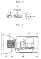
- the electrodeless lighting system includes a magnetron 500 including a filament therein and generating microwave, a resonator 710 including an electrodeless light bulb 700 and resonating microwave generated from the magnetron 500, a wave guide 600 guiding the microwave generated by the magnetron to the resonator 710, and a control unit 800 applying a filament current of a pre-set first current or larger to the filament during an initial starting stage and changing the filament current such that the filament current is the same or smaller than a second current which is smaller than the first current and applying the changed filament current to the filament.
- the electrodeless lighting system further includes a casing (C) and a high voltage generating unit installed in the internal space of the casing (C) and generating a high voltage.
- the magnetron 500 is installed in the internal space of the casing (C) and generates microwave having a high frequency as a high voltage generated from the high voltage generating unit is applied thereto.
- the wave guide 600 is installed in the internal space of the casing (C) and coupled to the magnetron 500 to guide microwave having a high frequency which has been oscillated from the magnetron 500.
- the wave guide 600 includes a first wave guide part having a rectangular wave guide space, to which the magnetron 500 is coupled, and a second wave guide part having a continuous wave guide space formed as the second wave guide part is bent from the first wave guide part and communicating with the resonance space of the resonator 710.
- the wave guide 600 is formed linearly.
- the magnetron 500 may be coupled to one side of the wave guide 600 and the wave guide space of the wave guide 600 may be connected with the resonance space of the resonator 700.
- the resonator 710 is installed at an outer side of the casing (C) and coupled to an outlet of the wave guide 600 to shield an external discharge of microwave to form a resonance mode.
- the electrodeless light bulb 700 is disposed at an inner side of the resonator 710 at an outer side of the casing (C) and contains a luminous material to be excited by microwave to emit light.
- the resonator 710 resonates microwave supplied from the magnetron 500 and has a mesh form to discharge to its maximum level light which has been converted from microwave energy by the electrodeless light bulb 700.
- the electrodeless lighting system includes a reflection shade 720 installed at the outer side of the casing (C), accommodating the resonator 710, and concentrating light emitted from the electrodeless light bulb 700 to a front side.
- the magnetron 500 is coupled such that a lengthwise direction of an antenna part is perpendicular to a lengthwise direction of the first guide part, and the resonator 710 is coupled such that its axial center is perpendicular to the lengthwise direction of the second wave guide part.
- the installation direction of the magnetron 500 and that of the resonator 710 are substantially perpendicular.
- the electrodeless lighting system further includes a driving unit 400 generating a filament current and a driving voltage.
- the driving unit 400 installed at the inner side of the casing (C), includes the high voltage generating unit.
- the control unit 800 is electrically connected with the driving unit 400, and as shown in FIG. 4 , the control unit 800 may have a form of a board or configured to be hermetically closed and installed at the inner side or outer side of the casing (C).
- the control unit 800 applies a first current, e.g., a current of 9A or larger, to the filament disposed within the magnetron (0 ⁇ t1) and determines whether or not the electrodeless lighting system has reached a normal state (t1 ⁇ t2).
- a first current e.g., a current of 9A or larger
- the control unit 800 reduces the filament current to a second current, e.g., 6A, or smaller, and applies the same (t2-t3).
- the control unit compares the number of pulses of light from the electrodeless light bulb and a pre-set reference number of pulses. When the number of pulses of light from the electrodeless light bulb is greater than the reference number of pulses according to the comparison result, the control unit determines that the electrodeless lighting system is in a normal state.
- control unit 800 applies a high voltage to the magnetron 500, and determines whether or not the electrodeless lighting system is in a normal state by comparing the number of pulses.
- the electrodeless lighting system may further include a cooling unit (not shown) for preventing overheating due to heat generated from the magnetron 500 and the high voltage generating unit, and in this case, the control unit controls the high voltage generating unit applying a high voltage to the magnetron 500 and the cooling unit.
- a cooling unit (not shown) for preventing overheating due to heat generated from the magnetron 500 and the high voltage generating unit, and in this case, the control unit controls the high voltage generating unit applying a high voltage to the magnetron 500 and the cooling unit.
- the electrodeless lighting system includes a rectifying unit 200 generating a DC voltage by converting commercial AC power 100, a driving unit 400 generating a filament current and driving voltage by converting the DC voltage, a magnetron 500 oscillated by the filament current and the driving voltage outputted from the driving unit 400 to output microwave to the wave guide, and a control unit 800 outputting a first control signal for converting the DC voltage into the filament current and a second control signal for converting the DC voltage into the driving voltage.
- the filament is provided in the magnetron 500.
- the rectifying unit 200 receives the commercial AC power 100 by using a bridge circuit or the like and converts it into a DC voltage.
- the converted DC voltage is a pulsating wave.
- the rectifying unit 200 includes a smoothing unit, and the smoothing unit is configured as a semiconductor device such as a capacitor to smooth the pulsating wave into a DC voltage.
- the driving unit 400 receives the smoothed DC voltage.
- the driving unit 400 converts the DC voltage inputted from the rectifying unit 200 into the filament current of the magnetron and the driving voltage for driving the magnetron based on control signals outputted from the control unit 800.
- the control signal is a frequency control signal or a duty control signal.
- the driving unit 400 receives a first control signal from the control unit 800, converts the DC voltage which has been received from the rectifying unit 200 based on the first control signal, and supplies the converted DC voltage to the filament of the magnetron. Also, the driving unit 400 receives the second control signal from the control unit 800, converts the DC voltage which has been received from the rectifying unit 200 based on the second control signal, and supplies a driving voltage for driving the magnetron.
- the control unit 800 applies the filament current of the pre-set current or larger to the filament during the initial starting stage and maintains it, and changes the filament current to the second current, which is smaller than the first current, or smaller in a pre-set normal state.
- 9 to 11 A is used as the first current
- 4 to 7A is used as the second current.
- the maneuverability of the electrodeless lighting system is secured during the initial starting stage, and a slightly higher current of 9 to 11 A is applied to the filament within the magnetron 500 in consideration of diurnal variations such as a change according to temperature characteristics of the magnetron. As shown in FIG.
- the control unit applies a first current, e.g., a current of 9A or larger, to the filament present within the magnetron during the initial starting stage (0 ⁇ t1) and determines whether or not the electrodeless lighting system has reached a normal state (t1 ⁇ t2).
- a first current e.g., a current of 9A or larger
- the control unit reduces the filament current such that it is the same or smaller than the second current, e.g., 6A, and applies the same (t2-t3).
- the driving unit 400 includes a first inverter unit 410 for varying the frequency of the DC voltage and converting it into a first AC voltage based on the first control, a second inverter unit 420 for varying the frequency of the DC voltage into a second AC voltage and converting it into a second AC voltage based on the second control signal, a first conversion unit 430 for converting the first AC voltage to generate the filament current, and a second conversion unit 440 for converting the second AC voltage to generate the driving voltage.
- the first inverter unit 410 and the second inverter unit 420 may be configured as a single inverter unit.
- the first conversion unit 430 and the second conversion unit 440 may be configured as a single conversion unit, namely, through a transformer.
- the driving unit 400 may further includes a high voltage generating unit 450 for increasing the driving voltage outputted from the second conversion unit 440 into a high voltage and applying the same to the magnetron.
- the first inverter unit 410 includes switching elements such as insulated gate bipolar transistors (IGBTs).
- the first inverter unit 410 receives a first control signal, a switching control signal, such as a frequency control signal, a duty control signal, or the like, from the control unit 800 and converts the DC voltage inputted from the rectifying unit 200 or from the power factor compensating unit 300 into a first AC voltage based on the first control signal.
- the first conversion unit 430 is a general transformer which converts the first AC voltage and supplies current to the filament of the magnetron according to the first inverter unit 410.
- the second inverter unit 420 are also configured to include switching elements such as IGBTs.
- the second inverter unit 420 receives a second control signal, a switching control signal, such as the frequency control signal, the duty control signal, or the like, and converts the DC voltage inputted from the rectifying unit 200 or the power factor compensating unit 300 based on the second control signal.
- the second conversion unit 440 is a general transformer which converts the second AC voltage according to the second inverter unit 420 to supply a driving voltage for driving the magnetron.
- the high voltage generating unit 450 increases the magnetron driving voltage which has been converted by the second conversion unit 550 and applies the increased high voltage to the magnetron 500.
- the electrodeless lighting system may further include the power factor compensating unit 300 connected between the rectifying unit 200 and the driving unit 400 and compensating for a power factor of the DC voltage outputted from the rectifying unit 200.
- the control unit 800 may store power factor compensation data in advance. Namely, the control unit 800 receives the commercial AC power 100, detects a variation of the commercial AC power 100 and applies corresponding power factor compensation data to the power factor compensating unit 300. Then, the power factor compensating unit 300 compensates for a power factor of the DC voltage outputted from the rectifying unit 200 by using the power factor compensation data. Also, the driving unit 400 receives the power factor-compensated DC voltage from the power factor compensating unit 300.
- the electrodeless lighting system may further include an input voltage detection unit 910 for detecting an input voltage inputted to the rectifying unit 200 and an input current detection unit 920 for detecting an input current inputted to the rectifying unit 200.
- the control unit 800 controls the power factor compensation unit 300 and the driving unit 400 including the first inverter unit 410 and the second inverter unit 420 based on the detected input voltage and input current.
- the electrodeless lighting system may further include a light detection unit 930 for detecting light of the electrodeless light bulb according to microwave outputted to the wave guide.
- the light detection unit 930 may be a photo transistor.
- the photo transistor may be installed at a bulb stage generating light through the electrodeless light bulb and counts the number of pulses of the light according to a rotation.
- the control unit 800 previously sets a reference number of pulses and compares the number of pulses of the detected light with the pre-set reference number of pulses. Upon comparison, when the number of pulses of the detected light is greater than the reference number of pulses, the control unit 800 determines that the electrodeless lighting system is in a normal state.
- the reference number of pulses may be set to vary depending on the characteristics of the electrodeless lighting system.
- the control unit 800 previously sets a reference duration. When a duration in which the current of the first current or larger is applied exceeds the pre-set reference duration, the control unit 800 applies a high driving voltage to the magnetron and determines whether or not the electrodeless lighting system is in a normal state by comparing the number of pulses. Namely, for example, the control unit 800 may set the reference duration as 4 seconds, and when four seconds has passed by, the control unit 800 outputs the second control signal to the second inverter unit 420 to apply a high voltage to the magnetron 500. And then, the control unit 800 determines whether or not the electrodeless lighting system has reached a stable lighting state by using the light detection unit 930.
- the control unit 800 reduces the filament current of the magnetron through the first control signal and supplies the current of the second current or smaller. Namely, the control unit 800 changes the filament current of the magnetron from a range of 9 to 11 A to a range of 4 to 7A. Accordingly, the frequency band of microwave outputted from the magnetron can be reduced and noise can be also reduced. Namely, as shown in FIG. 2 , when the filament current is reduced from 9A to 6A, noise in the regions A and C can be attenuated, the frequency band in the region B can be reduced, and a frequency interference with a wireless LAN can be avoided.
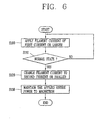
- a method for controlling an electrodeless lighting system includes an initial starting step (S100) of applying a filament current of a pre-set first current or larger of a magnetron; a normal state determining step (S110) of determining whether or not the electrodeless lighting system has reached a normal state; and a filament current changing step (S120) of changing the filament current such that it is a second current, which is smaller than the first current, or smaller when the electrodeless lighting system has reached the normal state.
- the configuration of the device is referred to FIGS. 4 and 5 .
- the normal state determining step (S110) may include: an initial start time determining step (not shown) of applying the filament current of the pre-set first current or larger to a filament and determining whether or not a pre-set reference duration has passed by; a driving voltage application step (not shown) of applying a high driving voltage to the magnetron when the duration in which the current of the first current or larger than the first current is applied exceeds the pre-set reference duration; a light detection step (not shown) of detecting light of the electrodeless light bulb according to microwave outputted from the magnetron to the wave guide; and a pulse number comparing step (not shown) of comparing the number of pulses of the detected light and a pre-set reference number of pulses, wherein when the number of pulses of the detected light is larger than the reference number of pulses, it is determined that the electrodeless lighting system is in a normal state.
- the method for controlling an electrodeless lighting system may further include: an input power maintaining step (S130) of uniformly maintaining entire power applied to the magnetron, and in the input power maintaining step (S130), the driving voltage of the magnetron is increased as high as the reduced filament current and supplied.
- the filament current of the pre-set first current or larger is applied to a filament and the filament current is maintained (S100).
- the first current 9 to 11A may be used. Namely, the maneuverability of the electrodeless lighting system is secured during the initial starting stage, and the slightly higher current of 9 to 11 A is applied to the filament within the magnetron 500 in consideration of diurnal variations such as a change according to temperature characteristics of the magnetron.
- the reference number of pulses may be set to vary depending on the characteristics of the electrodeless lighting system.
- the normal state determining step (S110) when the duration in which the current of the first current or larger is applied exceeds the pre-set reference duration, a high voltage is applied to the magnetron, and whether or not the electrodeless lighting system is in a normal state by comparing the number of pulses. For example, when the reference duration is set to 4 seconds, and after four seconds has passed by, a high voltage is applied to the magnetron according to the second control signal. And then, the light is detected to determine whether or not the electrodeless lighting system is in a normal state or has reached a stable lighting state.
- the filament current of the magnetron is reduced through the first control signal and a current of the second current or smaller is supplied (S120).
- a current of the second current or smaller is supplied (S120).
- the second current 4 to 7A may be used.
- the filament current of the magnetron is changed from a range of 9 to 11 A to a range of 4 to 7A. Accordingly, the frequency band of microwave outputted from the magnetron can be reduced and noise can be also reduced.
- the filament current is reduced from 9A to 6A, nose in the regions A and C can be attenuated, the frequency band in the region B can be reduced, and a frequency interference with a wireless LAN can be avoided.
- the driving voltage of the magnetron is increased to as high as the reduced filament current and supplied. Accordingly, a life span of the magnetron can be lengthened, noise can be reduced, and the operation efficiency of the electrodeless lighting system can be improved.
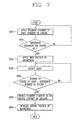
- a method for controlling an electrodeless lighting system includes: a first step (S200) of applying a filament current of a pre-set first current or larger of a magnetron to a filament to start the electrodeless lighting system; a second step (S200) of determining whether or not a pre-set reference duration has passed by after the first step; a third step (S300) of applying a high driving voltage to the magnetron when the pre-set reference duration has passed by according to the determination result of second step; a fourth step (S400) of detecting light of an electrodeless light bulb according to microwave outputted to a wave guide from the magnetron; a fifth step (S500) of comparing the number of pulses of the detected light and a pre-set reference number of pulses; a sixth step (S600) of determining that the electrodeless lighting system is in a normal state when the number of pulses of the detected light is larger than the reference number of pulses according to a comparison result of
- the filament current of the pre-set first current or larger is applied to the filament and maintained (S200), and in the pre-set normal state, the filament current is changed to the second current, which is smaller than the first current, or smaller (S120).
- the first current 9 to 11 A may be used. Namely, the maneuverability of the electrodeless lighting system is secured during the initial starting stage, and the slightly higher current of 9 to 11 A is applied to the filament within the magnetron 500 in consideration of diurnal variations such as a change according to temperature characteristics of the magnetron.
- the duration in which the current of the first current or larger is applied exceeds the pre-set reference duration (S210).
- a high voltage is applied to the magnetron (S220, and whether or not the electrodeless lighting system is in a normal state by comparing the number of pulses. For example, when the reference duration is set to 4 seconds, and after four seconds has passed by, a high voltage is applied to the magnetron according to the second control signal. And then, the light is detected to determine whether or not the electrodeless lighting system is in a normal state or has reached a stable lighting state.
- the reference number of pulses may be set to vary depending on the characteristics of the electrodeless lighting system.
- the filament current of the magnetron is reduced through the first control signal and a current of the second current or smaller is supplied (S250).
- a current of the second current or smaller is supplied (S250).
- 4 to 7A may be used as the second current.
- the filament current of the magnetron is changed from a range of 9 to 11 A to a range of 4 to 7A. Accordingly, the frequency band of microwave outputted from the magnetron can be reduced and noise can be also reduced.
- the filament current is reduced from 9A to 6A, nose in the regions A and C can be attenuated, the frequency band in the region B can be reduced, and a frequency interference with a wireless LAN can be avoided.
- the driving voltage of the magnetron is increased to as high as the reduced filament current and supplied (S260). Accordingly, a life span of the magnetron can be lengthened, noise can be reduced, and the operation efficiency of the electrodeless lighting system can be improved.
- a large filament current of the magnetron is applied to stably drive the magnetron, and during a normal state operation, a reduced filament current is applied, thus avoiding communication interference with a wireless LAN. Also, because the filament current is changed to be smaller, the life span of the magnetron can be lengthened and noise can be reduced. In addition, instead of reducing the filament current of the magnetron, the high driving voltage applied to the magnetron is increased and supplied, thus improving the operation efficiency of the electrodeless lighting system.
Landscapes
- Physics & Mathematics (AREA)
- Engineering & Computer Science (AREA)
- Plasma & Fusion (AREA)
- Electromagnetism (AREA)
- Circuit Arrangements For Discharge Lamps (AREA)
- Discharge-Lamp Control Circuits And Pulse- Feed Circuits (AREA)
Claims (7)
- Elektrodenloses Beleuchtungssystem mit:einem Magnetron (500), das einen Glühfaden aufweist und eine Mikrowelle erzeugt;einem Resonator (710), der einen elektrodenlosen Lampenkolben (700) aufweist und die vom Magnetron (500) erzeugte Mikrowelle in Resonanz versetzt; undeinen Wellenleiter (600), der die vom Magnetron (500) erzeugte Mikrowelle zum Resonator (710) leitet, dadurch gekennzeichnet, dass:das System ferner eine Steuereinheit (800) aufweist, die dafür eingerichtet ist, dem Glühfaden während einer Erststartphase einen Glühfadenstrom zuzuführen, der größer oder gleich einem vorgegebenen ersten Strom ist,eine Lichterfassungseinheit (930), die dafür eingerichtet ist, vom elektrodenlosen Lampenkolben (700) emittiertes Licht zu erfassen, eine Anzahl von Impulsen des erfassten Lichts zu zählen und die gezählte Anzahl von Impulsen an die Steuereinheit (800) zu übergeben,wobei die Steuereinheit (800) ferner dafür eingerichtet ist, die erfasste Anzahl von Impulsen mit einer vorgegebenen Bezugsanzahl von Impulsen zu vergleichen, um zu bestimmen, dass der elektrodenlose Lampenkörper (700) in einem normalen Zustand ist, wenn die erfasste Anzahl von Impulses größer ist als die Bezugsanzahl von Impulsen, und einen Glühfadenstrom, der kleiner oder gleich einem zweiten Strom ist, zu ändern und dem Glühfaden im normalen Zustand zuzuführen, wobei der zweite Strom kleiner ist als der erste Strom.
- Elektrodenloses Beleuchtungssystem nach Anspruch 1, wobei, wenn eine Zeitdauer, in der der Glühfadenstrom größer ist als der erste Strom, länger ist als eine vorgegebene Bezugszeitdauer, die Steuereinheit (800) eine hohe Spannung an das Magnetron (500) anlegt, bevor sie bestimmt, ob der elektrodenlose Lampenkolben (700) im normalen Zustand ist oder nicht, durch Vergleichen der Anzahl von Impulsen.
- Elektrodenloses Beleuchtungssystem nach Anspruch 1 oder 2, wobei der erste Strom 9 bis 11 A und der zweite Strom 4 bis 7 A beträgt.
- Verfahren zur Steuerung eines elektrodenlosen Beleuchtungssystems, wobei das System aufweist: ein Magnetron (500), das einen Glühfaden aufweist und eine Mikrowelle erzeugt, einen Resonator (710), der einen elektrodenlosen Lampenkolben (700) aufweist und die vom Magnetron (500) erzeugte Mikrowelle in Resonanz versetzt, und einen Wellenleiter (600), der die vom Magnetron (500) erzeugte Mikrowelle zum Resonator (710) leitet,
wobei das Verfahren die folgenden Schritte aufweist:einen Erststartschritt (S100; S200), der dazu dient, dem Glühfaden des Magnetrons (500) einen Glühfadenstrom gleich einem vorgegebenen ersten Strom oder größer zuzuführen;einen Normalzustandbestimmungsschritt (S110; S210, S220, S230, S240) zum Bestimmen, ob das elektrodenlose Beleuchtungssystem einen normalen Zustand erreicht hat oder nicht; undein Glühfadenstromänderungsschritt (S120; S250) zum Ändern des Glühfadenstroms von dem vorgegebenen ersten Strom oder größer zu einem zweiten Strom, der kleiner ist als der erste Strom, oder kleiner, wenn das elektrodenlose Beleuchtungssystem den normalen Zustand erreicht hat, wobei der Normalzustandbestimmungsschritt aufweist: einen Lichterfassungsschritt (S230) zur Erfassung von Licht des elektrodenlosen Lampenkolbens (700) gemäß einer von dem Magnetron (500) an den Wellenleiter (600) ausgegebenen Mikrowelle, und einen Impulsanzahlvergleichsschritt (S240) zum Vergleichen der Anzahl von Impulsen des erfassten Lichts und einer vorgegebenen Bezugsanzahl von Impulsen, wobei bestimmt wird, dass das elektrodenlose Beleuchtungssystem im normalen Zustand ist, wenn die Anzahl von Impulsen des erfassten Lichts größer ist als die Bezugsanzahl von Impulsen. - Verfahren nach Anspruch 4, wobei der Normalzustandsbestimmungsschritt ferner aufweist:einen Erststartzeitbestimmungsschritt (S210), der dazu dient, dem Glühfaden den Glühfadenstrom gleich dem vorgegebenen ersten Strom oder größer zuzuführen, und zu bestimmen, ob eine vorgegebene Bezugszeitdauer vergangen ist oder nicht; undeinen Ansteuerspannungsanlegeschritt (S220) zum Anlegen einer hohen Ansteuerspannung an das Magnetron (500), wenn die Zeitdauer, in der der Strom gleich dem ersten Strom oder größer als der erste Strom zugeführt wird, die vorgegebene Bezugszeitdauer überschreitet.
- Verfahren nach Anspruch 4 oder 5, ferner mit:einem Eingangsleistungbeibehaltungsschritt (S130) zum gleichmäßigen Beibehalten der dem Magnetron (500) zugeführten Gesamtleistung.
- Verfahren nach einem der Ansprüche 4 bis 6, wobei der erste Strom 9 bis 11 A und der zweite Strom 4 bis 7 A beträgt.
Applications Claiming Priority (1)
| Application Number | Priority Date | Filing Date | Title |
|---|---|---|---|
| KR1020090063179A KR101106409B1 (ko) | 2009-07-10 | 2009-07-10 | 무전극 조명기기 및 제어 방법 |
Publications (3)
| Publication Number | Publication Date |
|---|---|
| EP2280588A2 EP2280588A2 (de) | 2011-02-02 |
| EP2280588A3 EP2280588A3 (de) | 2012-05-09 |
| EP2280588B1 true EP2280588B1 (de) | 2013-03-13 |
Family
ID=42635232
Family Applications (1)
| Application Number | Title | Priority Date | Filing Date |
|---|---|---|---|
| EP10168778A Not-in-force EP2280588B1 (de) | 2009-07-10 | 2010-07-07 | Elektrodenloses Beleuchtungssystem und Steuerungsverfahren dafür |
Country Status (3)
| Country | Link |
|---|---|
| US (1) | US8410700B2 (de) |
| EP (1) | EP2280588B1 (de) |
| KR (1) | KR101106409B1 (de) |
Families Citing this family (1)
| Publication number | Priority date | Publication date | Assignee | Title |
|---|---|---|---|---|
| CN106851886B (zh) * | 2017-03-20 | 2020-03-17 | 东软医疗系统股份有限公司 | 确定磁控管的退灯丝电压的方法、装置及磁控管、加速器 |
Family Cites Families (12)
| Publication number | Priority date | Publication date | Assignee | Title |
|---|---|---|---|---|
| JPH07111918B2 (ja) * | 1987-07-28 | 1995-11-29 | 三菱電機株式会社 | マイクロ波放電光源装置 |
| US5847517A (en) * | 1996-07-10 | 1998-12-08 | Fusion Lighting, Inc. | Method and apparatus for igniting electrodeless lamp with ferroelectric emission |
| US6256016B1 (en) * | 1997-06-05 | 2001-07-03 | Logitech, Inc. | Optical detection system, device, and method utilizing optical matching |
| US6265830B1 (en) * | 1999-03-19 | 2001-07-24 | Nordson Corporation | Apparatus and method for supplying a regulated current to a magnetron filament |
| KR100343686B1 (ko) * | 1999-08-31 | 2002-07-19 | 엘지전자주식회사 | 마이크로 웨이브 조명기기의 밝기 조절장치 및 방법 |
| KR20010050569A (ko) * | 1999-09-21 | 2001-06-15 | 구자홍 | 마이크로 웨이브 조명시스템의 보호장치 및 방법 |
| KR20030026806A (ko) * | 2001-09-28 | 2003-04-03 | 주식회사 엘지이아이 | 마이크로파의 누출을 차단하는 장치 및 그 방법 |
| US6577074B1 (en) * | 2001-12-28 | 2003-06-10 | Fusion Uv Systems, Inc. | Lighting system |
| WO2003107725A1 (en) * | 2002-06-14 | 2003-12-24 | Fusion Lighting, Inc. | Microwave electrodeless lamp |
| KR100565343B1 (ko) * | 2003-08-14 | 2006-03-30 | 엘지전자 주식회사 | 무전극 조명기기의 구동장치 |
| JP2005142130A (ja) * | 2003-11-10 | 2005-06-02 | Matsushita Electric Works Ltd | 高圧放電灯点灯装置及び照明器具 |
| KR100864657B1 (ko) * | 2007-02-26 | 2008-10-23 | 엘지전자 주식회사 | 운전제어장치 및 방법 |
-
2009
- 2009-07-10 KR KR1020090063179A patent/KR101106409B1/ko not_active Expired - Fee Related
-
2010
- 2010-07-07 EP EP10168778A patent/EP2280588B1/de not_active Not-in-force
- 2010-07-09 US US12/833,232 patent/US8410700B2/en not_active Expired - Fee Related
Also Published As
| Publication number | Publication date |
|---|---|
| US8410700B2 (en) | 2013-04-02 |
| US20110006683A1 (en) | 2011-01-13 |
| KR101106409B1 (ko) | 2012-01-17 |
| EP2280588A3 (de) | 2012-05-09 |
| KR20110005557A (ko) | 2011-01-18 |
| EP2280588A2 (de) | 2011-02-02 |
Similar Documents
| Publication | Publication Date | Title |
|---|---|---|
| US8378582B2 (en) | Plasma lighting system | |
| TWI418259B (zh) | A power supply device and a microwave generator using the same | |
| US20080266012A1 (en) | Method for controlling high-frequency radiator | |
| KR20220071212A (ko) | 일정한 애노딕 임피던스를 갖는 마이크로웨이브 마그네트론 및 이를 이용하는 시스템들 | |
| US8410700B2 (en) | Electrodeless lighting system and control method thereof | |
| EP2273535A2 (de) | Elektrodenloses Beleuchtungssystem | |
| JP3477085B2 (ja) | 高周波加熱装置用インバータ電源 | |
| JP3927387B2 (ja) | 無電極ランプシステム | |
| CN101147423B (zh) | 用于驱动磁控管的电源 | |
| US7026590B2 (en) | Low-output microwave, lighting system and flicker removing method using the same | |
| US6661183B2 (en) | Apparatus and method for intercepting leakage of microwave | |
| JP3682912B2 (ja) | マグネトロン駆動電源回路 | |
| US7049764B2 (en) | Electrodeless lighting apparatus using microwave and method for controlling power thereof | |
| KR100677277B1 (ko) | 무전극 램프 시스템 | |
| KR100735098B1 (ko) | 전자렌지 및 그 전압제어방법 | |
| WO2003107725A1 (en) | Microwave electrodeless lamp | |
| KR950014132B1 (ko) | 마그네트론 구동장치 | |
| JP3855155B2 (ja) | 放電灯点灯装置 | |
| CN101258778A (zh) | 高频加热电源 | |
| JPS6269486A (ja) | 調理器 | |
| JP2003332090A (ja) | 無電極放電灯点灯装置 | |
| JPH01304687A (ja) | 高周波加熱装置 | |
| JP2003308958A (ja) | 高周波加熱電源装置 | |
| JP2004095500A (ja) | 高周波加熱装置 | |
| KR20010066583A (ko) | 인버터 전자레인지의 출력제어방법 |
Legal Events
| Date | Code | Title | Description |
|---|---|---|---|
| PUAI | Public reference made under article 153(3) epc to a published international application that has entered the european phase |
Free format text: ORIGINAL CODE: 0009012 |
|
| 17P | Request for examination filed |
Effective date: 20100707 |
|
| AK | Designated contracting states |
Kind code of ref document: A2 Designated state(s): AL AT BE BG CH CY CZ DE DK EE ES FI FR GB GR HR HU IE IS IT LI LT LU LV MC MK MT NL NO PL PT RO SE SI SK SM TR |
|
| AX | Request for extension of the european patent |
Extension state: BA ME RS |
|
| PUAL | Search report despatched |
Free format text: ORIGINAL CODE: 0009013 |
|
| AK | Designated contracting states |
Kind code of ref document: A3 Designated state(s): AL AT BE BG CH CY CZ DE DK EE ES FI FR GB GR HR HU IE IS IT LI LT LU LV MC MK MT NL NO PL PT RO SE SI SK SM TR |
|
| AX | Request for extension of the european patent |
Extension state: BA ME RS |
|
| RIC1 | Information provided on ipc code assigned before grant |
Ipc: H05B 41/38 20060101ALI20120403BHEP Ipc: H05B 41/24 20060101AFI20120403BHEP Ipc: H05B 41/28 20060101ALI20120403BHEP |
|
| GRAP | Despatch of communication of intention to grant a patent |
Free format text: ORIGINAL CODE: EPIDOSNIGR1 |
|
| RIC1 | Information provided on ipc code assigned before grant |
Ipc: H05B 41/38 20060101ALI20120904BHEP Ipc: H05B 41/24 20060101AFI20120904BHEP Ipc: H05B 41/28 20060101ALI20120904BHEP |
|
| GRAS | Grant fee paid |
Free format text: ORIGINAL CODE: EPIDOSNIGR3 |
|
| GRAA | (expected) grant |
Free format text: ORIGINAL CODE: 0009210 |
|
| AK | Designated contracting states |
Kind code of ref document: B1 Designated state(s): AL AT BE BG CH CY CZ DE DK EE ES FI FR GB GR HR HU IE IS IT LI LT LU LV MC MK MT NL NO PL PT RO SE SI SK SM TR |
|
| REG | Reference to a national code |
Ref country code: GB Ref legal event code: FG4D |
|
| REG | Reference to a national code |
Ref country code: CH Ref legal event code: EP Ref country code: AT Ref legal event code: REF Ref document number: 601452 Country of ref document: AT Kind code of ref document: T Effective date: 20130315 |
|
| REG | Reference to a national code |
Ref country code: IE Ref legal event code: FG4D |
|
| REG | Reference to a national code |
Ref country code: DE Ref legal event code: R096 Ref document number: 602010005388 Country of ref document: DE Effective date: 20130508 |
|
| PG25 | Lapsed in a contracting state [announced via postgrant information from national office to epo] |
Ref country code: NO Free format text: LAPSE BECAUSE OF FAILURE TO SUBMIT A TRANSLATION OF THE DESCRIPTION OR TO PAY THE FEE WITHIN THE PRESCRIBED TIME-LIMIT Effective date: 20130613 Ref country code: SE Free format text: LAPSE BECAUSE OF FAILURE TO SUBMIT A TRANSLATION OF THE DESCRIPTION OR TO PAY THE FEE WITHIN THE PRESCRIBED TIME-LIMIT Effective date: 20130313 Ref country code: ES Free format text: LAPSE BECAUSE OF FAILURE TO SUBMIT A TRANSLATION OF THE DESCRIPTION OR TO PAY THE FEE WITHIN THE PRESCRIBED TIME-LIMIT Effective date: 20130624 Ref country code: LT Free format text: LAPSE BECAUSE OF FAILURE TO SUBMIT A TRANSLATION OF THE DESCRIPTION OR TO PAY THE FEE WITHIN THE PRESCRIBED TIME-LIMIT Effective date: 20130313 Ref country code: BG Free format text: LAPSE BECAUSE OF FAILURE TO SUBMIT A TRANSLATION OF THE DESCRIPTION OR TO PAY THE FEE WITHIN THE PRESCRIBED TIME-LIMIT Effective date: 20130613 |
|
| REG | Reference to a national code |
Ref country code: AT Ref legal event code: MK05 Ref document number: 601452 Country of ref document: AT Kind code of ref document: T Effective date: 20130313 |
|
| REG | Reference to a national code |
Ref country code: NL Ref legal event code: VDEP Effective date: 20130313 |
|
| REG | Reference to a national code |
Ref country code: LT Ref legal event code: MG4D |
|
| PG25 | Lapsed in a contracting state [announced via postgrant information from national office to epo] |
Ref country code: GR Free format text: LAPSE BECAUSE OF FAILURE TO SUBMIT A TRANSLATION OF THE DESCRIPTION OR TO PAY THE FEE WITHIN THE PRESCRIBED TIME-LIMIT Effective date: 20130614 Ref country code: LV Free format text: LAPSE BECAUSE OF FAILURE TO SUBMIT A TRANSLATION OF THE DESCRIPTION OR TO PAY THE FEE WITHIN THE PRESCRIBED TIME-LIMIT Effective date: 20130313 Ref country code: SI Free format text: LAPSE BECAUSE OF FAILURE TO SUBMIT A TRANSLATION OF THE DESCRIPTION OR TO PAY THE FEE WITHIN THE PRESCRIBED TIME-LIMIT Effective date: 20130313 Ref country code: FI Free format text: LAPSE BECAUSE OF FAILURE TO SUBMIT A TRANSLATION OF THE DESCRIPTION OR TO PAY THE FEE WITHIN THE PRESCRIBED TIME-LIMIT Effective date: 20130313 |
|
| PG25 | Lapsed in a contracting state [announced via postgrant information from national office to epo] |
Ref country code: BE Free format text: LAPSE BECAUSE OF FAILURE TO SUBMIT A TRANSLATION OF THE DESCRIPTION OR TO PAY THE FEE WITHIN THE PRESCRIBED TIME-LIMIT Effective date: 20130313 Ref country code: HR Free format text: LAPSE BECAUSE OF FAILURE TO SUBMIT A TRANSLATION OF THE DESCRIPTION OR TO PAY THE FEE WITHIN THE PRESCRIBED TIME-LIMIT Effective date: 20130313 |
|
| PG25 | Lapsed in a contracting state [announced via postgrant information from national office to epo] |
Ref country code: SK Free format text: LAPSE BECAUSE OF FAILURE TO SUBMIT A TRANSLATION OF THE DESCRIPTION OR TO PAY THE FEE WITHIN THE PRESCRIBED TIME-LIMIT Effective date: 20130313 Ref country code: IS Free format text: LAPSE BECAUSE OF FAILURE TO SUBMIT A TRANSLATION OF THE DESCRIPTION OR TO PAY THE FEE WITHIN THE PRESCRIBED TIME-LIMIT Effective date: 20130713 Ref country code: EE Free format text: LAPSE BECAUSE OF FAILURE TO SUBMIT A TRANSLATION OF THE DESCRIPTION OR TO PAY THE FEE WITHIN THE PRESCRIBED TIME-LIMIT Effective date: 20130313 Ref country code: RO Free format text: LAPSE BECAUSE OF FAILURE TO SUBMIT A TRANSLATION OF THE DESCRIPTION OR TO PAY THE FEE WITHIN THE PRESCRIBED TIME-LIMIT Effective date: 20130313 Ref country code: PT Free format text: LAPSE BECAUSE OF FAILURE TO SUBMIT A TRANSLATION OF THE DESCRIPTION OR TO PAY THE FEE WITHIN THE PRESCRIBED TIME-LIMIT Effective date: 20130715 Ref country code: NL Free format text: LAPSE BECAUSE OF FAILURE TO SUBMIT A TRANSLATION OF THE DESCRIPTION OR TO PAY THE FEE WITHIN THE PRESCRIBED TIME-LIMIT Effective date: 20130313 Ref country code: CZ Free format text: LAPSE BECAUSE OF FAILURE TO SUBMIT A TRANSLATION OF THE DESCRIPTION OR TO PAY THE FEE WITHIN THE PRESCRIBED TIME-LIMIT Effective date: 20130313 Ref country code: AT Free format text: LAPSE BECAUSE OF FAILURE TO SUBMIT A TRANSLATION OF THE DESCRIPTION OR TO PAY THE FEE WITHIN THE PRESCRIBED TIME-LIMIT Effective date: 20130313 |
|
| PG25 | Lapsed in a contracting state [announced via postgrant information from national office to epo] |
Ref country code: PL Free format text: LAPSE BECAUSE OF FAILURE TO SUBMIT A TRANSLATION OF THE DESCRIPTION OR TO PAY THE FEE WITHIN THE PRESCRIBED TIME-LIMIT Effective date: 20130313 |
|
| PLBE | No opposition filed within time limit |
Free format text: ORIGINAL CODE: 0009261 |
|
| STAA | Information on the status of an ep patent application or granted ep patent |
Free format text: STATUS: NO OPPOSITION FILED WITHIN TIME LIMIT |
|
| PG25 | Lapsed in a contracting state [announced via postgrant information from national office to epo] |
Ref country code: DK Free format text: LAPSE BECAUSE OF FAILURE TO SUBMIT A TRANSLATION OF THE DESCRIPTION OR TO PAY THE FEE WITHIN THE PRESCRIBED TIME-LIMIT Effective date: 20130313 |
|
| REG | Reference to a national code |
Ref country code: DE Ref legal event code: R119 Ref document number: 602010005388 Country of ref document: DE |
|
| 26N | No opposition filed |
Effective date: 20131216 |
|
| PG25 | Lapsed in a contracting state [announced via postgrant information from national office to epo] |
Ref country code: MC Free format text: LAPSE BECAUSE OF FAILURE TO SUBMIT A TRANSLATION OF THE DESCRIPTION OR TO PAY THE FEE WITHIN THE PRESCRIBED TIME-LIMIT Effective date: 20130313 Ref country code: IT Free format text: LAPSE BECAUSE OF FAILURE TO SUBMIT A TRANSLATION OF THE DESCRIPTION OR TO PAY THE FEE WITHIN THE PRESCRIBED TIME-LIMIT Effective date: 20130313 |
|
| REG | Reference to a national code |
Ref country code: DE Ref legal event code: R097 Ref document number: 602010005388 Country of ref document: DE Effective date: 20131216 |
|
| REG | Reference to a national code |
Ref country code: IE Ref legal event code: MM4A |
|
| REG | Reference to a national code |
Ref country code: DE Ref legal event code: R119 Ref document number: 602010005388 Country of ref document: DE Effective date: 20140201 |
|
| PG25 | Lapsed in a contracting state [announced via postgrant information from national office to epo] |
Ref country code: DE Free format text: LAPSE BECAUSE OF NON-PAYMENT OF DUE FEES Effective date: 20140201 |
|
| PG25 | Lapsed in a contracting state [announced via postgrant information from national office to epo] |
Ref country code: IE Free format text: LAPSE BECAUSE OF NON-PAYMENT OF DUE FEES Effective date: 20130707 |
|
| REG | Reference to a national code |
Ref country code: CH Ref legal event code: PL |
|
| PG25 | Lapsed in a contracting state [announced via postgrant information from national office to epo] |
Ref country code: LI Free format text: LAPSE BECAUSE OF NON-PAYMENT OF DUE FEES Effective date: 20140731 Ref country code: CH Free format text: LAPSE BECAUSE OF NON-PAYMENT OF DUE FEES Effective date: 20140731 |
|
| PG25 | Lapsed in a contracting state [announced via postgrant information from national office to epo] |
Ref country code: SM Free format text: LAPSE BECAUSE OF FAILURE TO SUBMIT A TRANSLATION OF THE DESCRIPTION OR TO PAY THE FEE WITHIN THE PRESCRIBED TIME-LIMIT Effective date: 20130313 |
|
| REG | Reference to a national code |
Ref country code: FR Ref legal event code: PLFP Year of fee payment: 6 |
|
| PG25 | Lapsed in a contracting state [announced via postgrant information from national office to epo] |
Ref country code: TR Free format text: LAPSE BECAUSE OF FAILURE TO SUBMIT A TRANSLATION OF THE DESCRIPTION OR TO PAY THE FEE WITHIN THE PRESCRIBED TIME-LIMIT Effective date: 20130313 Ref country code: MT Free format text: LAPSE BECAUSE OF FAILURE TO SUBMIT A TRANSLATION OF THE DESCRIPTION OR TO PAY THE FEE WITHIN THE PRESCRIBED TIME-LIMIT Effective date: 20130313 Ref country code: CY Free format text: LAPSE BECAUSE OF FAILURE TO SUBMIT A TRANSLATION OF THE DESCRIPTION OR TO PAY THE FEE WITHIN THE PRESCRIBED TIME-LIMIT Effective date: 20130313 |
|
| PG25 | Lapsed in a contracting state [announced via postgrant information from national office to epo] |
Ref country code: HU Free format text: LAPSE BECAUSE OF FAILURE TO SUBMIT A TRANSLATION OF THE DESCRIPTION OR TO PAY THE FEE WITHIN THE PRESCRIBED TIME-LIMIT; INVALID AB INITIO Effective date: 20100707 Ref country code: LU Free format text: LAPSE BECAUSE OF NON-PAYMENT OF DUE FEES Effective date: 20130707 Ref country code: MK Free format text: LAPSE BECAUSE OF FAILURE TO SUBMIT A TRANSLATION OF THE DESCRIPTION OR TO PAY THE FEE WITHIN THE PRESCRIBED TIME-LIMIT Effective date: 20130313 |
|
| REG | Reference to a national code |
Ref country code: FR Ref legal event code: PLFP Year of fee payment: 7 |
|
| REG | Reference to a national code |
Ref country code: FR Ref legal event code: PLFP Year of fee payment: 8 |
|
| REG | Reference to a national code |
Ref country code: FR Ref legal event code: PLFP Year of fee payment: 9 |
|
| PG25 | Lapsed in a contracting state [announced via postgrant information from national office to epo] |
Ref country code: AL Free format text: LAPSE BECAUSE OF FAILURE TO SUBMIT A TRANSLATION OF THE DESCRIPTION OR TO PAY THE FEE WITHIN THE PRESCRIBED TIME-LIMIT Effective date: 20130313 |
|
| PGFP | Annual fee paid to national office [announced via postgrant information from national office to epo] |
Ref country code: FR Payment date: 20190605 Year of fee payment: 10 |
|
| PGFP | Annual fee paid to national office [announced via postgrant information from national office to epo] |
Ref country code: GB Payment date: 20190605 Year of fee payment: 10 |
|
| GBPC | Gb: european patent ceased through non-payment of renewal fee |
Effective date: 20200707 |
|
| PG25 | Lapsed in a contracting state [announced via postgrant information from national office to epo] |
Ref country code: FR Free format text: LAPSE BECAUSE OF NON-PAYMENT OF DUE FEES Effective date: 20200731 Ref country code: GB Free format text: LAPSE BECAUSE OF NON-PAYMENT OF DUE FEES Effective date: 20200707 |