EP2280220B1 - Module de lumière pour un phare de véhicule automobile - Google Patents
Module de lumière pour un phare de véhicule automobile Download PDFInfo
- Publication number
- EP2280220B1 EP2280220B1 EP10004955.0A EP10004955A EP2280220B1 EP 2280220 B1 EP2280220 B1 EP 2280220B1 EP 10004955 A EP10004955 A EP 10004955A EP 2280220 B1 EP2280220 B1 EP 2280220B1
- Authority
- EP
- European Patent Office
- Prior art keywords
- light
- vehicle
- module
- headlamp
- dark boundary
- Prior art date
- Legal status (The legal status is an assumption and is not a legal conclusion. Google has not performed a legal analysis and makes no representation as to the accuracy of the status listed.)
- Not-in-force
Links
- 238000009826 distribution Methods 0.000 claims description 111
- 230000003287 optical effect Effects 0.000 claims description 30
- 230000003044 adaptive effect Effects 0.000 claims description 12
- 238000005286 illumination Methods 0.000 claims description 5
- 239000004065 semiconductor Substances 0.000 claims description 5
- 238000003384 imaging method Methods 0.000 claims description 4
- 230000004297 night vision Effects 0.000 claims description 4
- 230000005855 radiation Effects 0.000 claims description 3
- 238000001454 recorded image Methods 0.000 claims 1
- 230000007613 environmental effect Effects 0.000 description 7
- 230000007704 transition Effects 0.000 description 6
- 241001465754 Metazoa Species 0.000 description 4
- 230000009471 action Effects 0.000 description 2
- 239000012141 concentrate Substances 0.000 description 2
- 238000001514 detection method Methods 0.000 description 2
- 239000012780 transparent material Substances 0.000 description 2
- FGRBYDKOBBBPOI-UHFFFAOYSA-N 10,10-dioxo-2-[4-(N-phenylanilino)phenyl]thioxanthen-9-one Chemical compound O=C1c2ccccc2S(=O)(=O)c2ccc(cc12)-c1ccc(cc1)N(c1ccccc1)c1ccccc1 FGRBYDKOBBBPOI-UHFFFAOYSA-N 0.000 description 1
- 230000000454 anti-cipatory effect Effects 0.000 description 1
- 238000003491 array Methods 0.000 description 1
- 238000004891 communication Methods 0.000 description 1
- 230000008878 coupling Effects 0.000 description 1
- 238000010168 coupling process Methods 0.000 description 1
- 238000005859 coupling reaction Methods 0.000 description 1
- 230000000694 effects Effects 0.000 description 1
- 230000004438 eyesight Effects 0.000 description 1
- 230000004313 glare Effects 0.000 description 1
- 239000011521 glass Substances 0.000 description 1
- 231100001261 hazardous Toxicity 0.000 description 1
- 230000003993 interaction Effects 0.000 description 1
- 230000001788 irregular Effects 0.000 description 1
- 239000000203 mixture Substances 0.000 description 1
- 229920003023 plastic Polymers 0.000 description 1
- 230000009467 reduction Effects 0.000 description 1
- 230000000246 remedial effect Effects 0.000 description 1
- 230000000630 rising effect Effects 0.000 description 1
- 238000002604 ultrasonography Methods 0.000 description 1
Images


Classifications
-
- F—MECHANICAL ENGINEERING; LIGHTING; HEATING; WEAPONS; BLASTING
- F21—LIGHTING
- F21S—NON-PORTABLE LIGHTING DEVICES; SYSTEMS THEREOF; VEHICLE LIGHTING DEVICES SPECIALLY ADAPTED FOR VEHICLE EXTERIORS
- F21S41/00—Illuminating devices specially adapted for vehicle exteriors, e.g. headlamps
- F21S41/60—Illuminating devices specially adapted for vehicle exteriors, e.g. headlamps characterised by a variable light distribution
- F21S41/68—Illuminating devices specially adapted for vehicle exteriors, e.g. headlamps characterised by a variable light distribution by acting on screens
- F21S41/683—Illuminating devices specially adapted for vehicle exteriors, e.g. headlamps characterised by a variable light distribution by acting on screens by moving screens
- F21S41/686—Blades, i.e. screens moving in a vertical plane
-
- B—PERFORMING OPERATIONS; TRANSPORTING
- B60—VEHICLES IN GENERAL
- B60Q—ARRANGEMENT OF SIGNALLING OR LIGHTING DEVICES, THE MOUNTING OR SUPPORTING THEREOF OR CIRCUITS THEREFOR, FOR VEHICLES IN GENERAL
- B60Q1/00—Arrangement of optical signalling or lighting devices, the mounting or supporting thereof or circuits therefor
- B60Q1/02—Arrangement of optical signalling or lighting devices, the mounting or supporting thereof or circuits therefor the devices being primarily intended to illuminate the way ahead or to illuminate other areas of way or environments
- B60Q1/04—Arrangement of optical signalling or lighting devices, the mounting or supporting thereof or circuits therefor the devices being primarily intended to illuminate the way ahead or to illuminate other areas of way or environments the devices being headlights
- B60Q1/06—Arrangement of optical signalling or lighting devices, the mounting or supporting thereof or circuits therefor the devices being primarily intended to illuminate the way ahead or to illuminate other areas of way or environments the devices being headlights adjustable, e.g. remotely-controlled from inside vehicle
- B60Q1/08—Arrangement of optical signalling or lighting devices, the mounting or supporting thereof or circuits therefor the devices being primarily intended to illuminate the way ahead or to illuminate other areas of way or environments the devices being headlights adjustable, e.g. remotely-controlled from inside vehicle automatically
- B60Q1/085—Arrangement of optical signalling or lighting devices, the mounting or supporting thereof or circuits therefor the devices being primarily intended to illuminate the way ahead or to illuminate other areas of way or environments the devices being headlights adjustable, e.g. remotely-controlled from inside vehicle automatically due to special conditions, e.g. adverse weather, type of road, badly illuminated road signs or potential dangers
-
- F—MECHANICAL ENGINEERING; LIGHTING; HEATING; WEAPONS; BLASTING
- F21—LIGHTING
- F21S—NON-PORTABLE LIGHTING DEVICES; SYSTEMS THEREOF; VEHICLE LIGHTING DEVICES SPECIALLY ADAPTED FOR VEHICLE EXTERIORS
- F21S41/00—Illuminating devices specially adapted for vehicle exteriors, e.g. headlamps
- F21S41/60—Illuminating devices specially adapted for vehicle exteriors, e.g. headlamps characterised by a variable light distribution
- F21S41/65—Illuminating devices specially adapted for vehicle exteriors, e.g. headlamps characterised by a variable light distribution by acting on light sources
- F21S41/663—Illuminating devices specially adapted for vehicle exteriors, e.g. headlamps characterised by a variable light distribution by acting on light sources by switching light sources
-
- F—MECHANICAL ENGINEERING; LIGHTING; HEATING; WEAPONS; BLASTING
- F21—LIGHTING
- F21S—NON-PORTABLE LIGHTING DEVICES; SYSTEMS THEREOF; VEHICLE LIGHTING DEVICES SPECIALLY ADAPTED FOR VEHICLE EXTERIORS
- F21S41/00—Illuminating devices specially adapted for vehicle exteriors, e.g. headlamps
- F21S41/60—Illuminating devices specially adapted for vehicle exteriors, e.g. headlamps characterised by a variable light distribution
- F21S41/68—Illuminating devices specially adapted for vehicle exteriors, e.g. headlamps characterised by a variable light distribution by acting on screens
- F21S41/683—Illuminating devices specially adapted for vehicle exteriors, e.g. headlamps characterised by a variable light distribution by acting on screens by moving screens
- F21S41/689—Flaps, i.e. screens pivoting around one of their edges
-
- B—PERFORMING OPERATIONS; TRANSPORTING
- B60—VEHICLES IN GENERAL
- B60Q—ARRANGEMENT OF SIGNALLING OR LIGHTING DEVICES, THE MOUNTING OR SUPPORTING THEREOF OR CIRCUITS THEREFOR, FOR VEHICLES IN GENERAL
- B60Q2300/00—Indexing codes for automatically adjustable headlamps or automatically dimmable headlamps
- B60Q2300/40—Indexing codes relating to other road users or special conditions
- B60Q2300/45—Special conditions, e.g. pedestrians, road signs or potential dangers
Definitions
- the present invention relates to a light module for a motor vehicle headlight for generating an adaptive light distribution, as from the generic document WO 2009/039882 known.
- the invention also relates to a motor vehicle headlight with a light module of the type mentioned.
- the present invention also relates to a headlamp system for a motor vehicle for illuminating a roadway in front of the motor vehicle with an adaptive light distribution.
- the headlamp system comprises at the front of the vehicle at least one vehicle headlight on its own traffic side and on the oncoming traffic side, means for detecting an image of an area in front of the vehicle and means for evaluating the detected image for detecting objects in front of the vehicle.
- At least one of the headlights has at least one light module for generating an adaptive light distribution of the aforementioned type.
- a light module of the type mentioned is for example from the DE 10 2007 050 348 A1 known.
- a diaphragm arrangement which has a plurality of diaphragm elements extending essentially transversely to the optical axis of the light module and arranged around a parallel axis of rotation arranged parallel to the optical axis.
- the panel elements have top edges with different contours.
- An effective upper edge of the diaphragm arrangement arranged in the beam path is achieved by one of the upper edges or by overlapping a plurality of upper edges.
- the effective upper edge of the diaphragm arrangement can be used to produce a dimmed light distribution with a be introduced substantially horizontally extending light-dark boundary in the beam path of the light emitted from the light source and / or bundled by the primary optics light.
- Traffic conditions include, for example, preceding or oncoming road users, detected objects (persons or objects) on the road or at the edge of the road, the traffic density, the road condition, etc.
- Environmental conditions include in particular the weather (eg fog, rain, snow, ice) or the time of day or the current lighting conditions (eg sun, clouds, dusk, darkness).
- a bad weather light (a further development of the fog light), a conventional low-beam distribution with symmetrical or asymmetrical cut-off, a country road, a motorway light, a city light, a Generalfernlicht or a conventional high beam can be generated, for the high beam the effective upper edge of the diaphragm arrangement is arranged virtually completely outside the beam path.
- the traffic situation and the environmental conditions in the vicinity of the vehicle can be detected by means of suitable sensors.
- Cameras for visible light, IR or UV radiation
- radar sensors for ultrasonic sensors or other suitable sensors can be used to detect the traffic conditions, in particular the traffic ahead of the vehicle.
- the images of the area in front of the vehicle detected by these sensors are evaluated by a computer unit using suitable algorithms and used to control the diaphragm arrangement and thus ultimately to generate an adaptive light distribution in front of the vehicle.
- Environmental conditions may be detected by rain or snow sensors, light sensors, a thermometer and other suitable sensors. A combined use of several different sensors for detecting the traffic and environmental conditions is conceivable.
- a diaphragm arrangement which comprises a free-form roller rotatable about a horizontal axis of rotation extending transversely to the optical axis, on the lateral surface of which a plurality of upper edges extending transversely to the optical axis and circumferentially spaced from one another are formed with different contour profiles.
- the roller can be rotated about the axis of rotation such that the corresponding upper edge is introduced in the beam path of the light emitted by the light source and / or focused by the primary optics.
- the upper edge of the roller which is in each case arranged in the beam path, forms the effective upper edge of the diaphragm arrangement.
- the light modules described for generating an adaptive light distribution already offer a considerable gain in safety over conventional light modules which only produce a light function (eg dipped beam, high beam or fog light) or can be switched between different light functions, since a multiplicity of different light functions are available and for the respective traffic and environmental situation the optimal light distribution can be selected.
- a light function eg dipped beam, high beam or fog light
- the known light modules still have potential in terms of improving the driver's visibility, but without leading to dazzling the other road users.
- the present invention is therefore based on the object to provide a simple and cost-effective way to improve the visibility of the driver of a motor vehicle, especially with regard to potentially traffic-endangering objects in the area in front of the motor vehicle, but without leading to dazzling other road users.
- the dimmed light distribution with the horizontal light-dark boundary and the illuminated area formed above the light-dark boundary at least be activated briefly to illuminate the detected object with the area arranged above the light-dark boundary.
- the attention of the driver is thereby directed to the detected object.
- the driver can avoid the detected and illuminated object, reduce the vehicle speed or take other suitable measures for avoiding a collision with the object and / or endangering the object.
- dazzling becomes more anticipatory or more responsive Road users largely avoided because the extension of the light-dark boundary formed above the illuminated area in the horizontal direction is only a few degrees and is usually activated only for a relatively short time.
- the horizontal position of the illuminated area of the light distribution arranged above the light-dark boundary can be varied.
- the illuminated area can always be aimed precisely at the detected object and illuminate the object clearly, so that it is immediately recognizable and identifiable by the driver. This is important because the action to be taken by the driver to avoid a collision with the object or endangering the object will depend primarily on the nature of the object. For example. in playing children or animals, the choice of action will be different than, for example, in the case of objects.
- the light module comprises means for horizontally pivoting the light module or a part thereof in order to direct the illuminated area above the horizontal light-dark boundary to objects detected in front of the vehicle.
- the illuminated area in the horizontal direction can be selectively moved to a position where potentially traffic-endangering objects, such as persons or animals, which cross the roadway in front of the vehicle, have been detected. Due to the small extent of the illuminated area in the horizontal direction of only a few angular degrees, the detected object can be selectively illuminated without dawning and / or oncoming traffic participants are dazzled.
- the light module has a secondary optics, preferably in the form of a projection lens, for imaging the light passed by the effective upper edge of the diaphragm arrangement on a roadway in front of the vehicle.
- the secondary optics depicts the effective upper edge of the diaphragm arrangement as a light-dark boundary of the light distribution on the roadway.
- the light module would be as a so-called projection module educated.
- the projection lens is preferably provided with regular or irregular microstructures having a height of about 3-30 microns to the base surface of the lens.
- the surface of the lens is preferably plano-convex or meniscus-shaped.
- the illuminated area above the horizontal light-dark boundary has an extent of approximately 2 ° horizontally and approximately 3 ° to 5 ° vertically.
- the width of the illuminated area is measured from an approximately vertical lateral bright-dark boundary to the opposite approximately vertical lateral bright-dark boundary.
- the height of the illuminated area is from the horizontal light-dark border up to the upper end of the illuminated area measured.
- the illuminated area in particular in the vertical direction, have an extension of significantly more than 3 °, which is advantageous for illuminating objects far above the road, for example, persons on a highway bridge.
- the extent in the horizontal direction can be significantly more than 2 ° in certain situations.
- the illuminated area above the horizontal cut-off in the horizontal direction is positioned so that it illuminates the edge of the road on its own side, that the illuminated area relatively far in the direction of its own traffic side on the edge of the road extends outwards.
- the width and the height of the illuminated area above the light-dark boundary during the intended operation of the light module is variable.
- the width and height of the illuminated area above the light-dark boundary is fixed and does not vary during operation of the light module.
- the means for horizontal pivoting of the light module are provided for realizing a dynamic cornering function of the headlamp.
- means could be used for pivoting the illuminated area above the horizontal light-dark boundary, which are actually present anyway for another purpose in the light module or the headlight.
- additional mechanical components actuators, gearbox, coupling elements, etc.
- the diaphragm arrangement is designed as a free-form roller rotatable about a horizontal axis of rotation running transversely to the optical axis, on the lateral surface of which a plurality of upper edges running transversely to the optical axis and spaced apart in the circumferential direction are formed with different contour profiles wherein one of the upper edges forms the effective upper edge of the diaphragm arrangement for producing the dimmed light distribution with the illuminated area provided above the cut-off line.
- the upper edge for generating the dimmed light distribution with the illuminated area provided above the cut-off line has substantially the same shape as an upper edge, which is used to generate a light distribution with a horizontal light-dark boundary (eg dipped beam, fog light, etc.). ) serves. In addition, however, a slot is provided in the upper edge, which serves to generate the illuminated area of the light distribution above the cut-off line.
- a horizontal light-dark boundary eg dipped beam, fog light, etc.
- the horizontal cut-off line can be symmetrical, that is to say the entire cut-off line extends slightly (approximately -1 °) below the vertical VV on the screen located in front of the vehicle.
- the horizontal cut-off line can also be formed asymmetrically, with a horizontal section on the oncoming traffic side and a contrast higher section on the own traffic side.
- the transition from the lower portion of the cut-off line on the oncoming traffic side to the higher portion on the own traffic side may be either stepped or in another way, for example by an oblique increase, in particular a 15 ° increase done.
- the space on the lateral surface is limited to the arrangement of the various upper edges with different contour curves.
- the spacing in the circumferential direction of adjacent upper edges applied on the lateral surface must be so large that adjacent upper edges do not interfere with the generation of the desired light distribution. Therefore, only a limited number of different upper edges can be arranged on the lateral surface of the roller in a diaphragm arrangement designed in this way.
- another top edge is replaced, which serves to generate a light distribution, which is rarely activated in practice.
- Such a light distribution is for example the Generalfernlicht on the opposite side. This is generated by the arranged in the bow of the vehicle on the opposite side of the headlight or a light module of this headlight.
- the spotlight which is located in the bow of the vehicle on its own traffic side, forms the corresponding partial high beam for its own traffic side.
- the dimmed light distribution provided above the cut-off light and illuminated area produce.
- the simplified system only the arranged on the own traffic side headlamps for generating the dimmed light distribution with above the light-dark boundary provided illuminated area may be formed.
- the diaphragm arrangement has a plurality of diaphragm elements extending essentially transversely to the optical axis of the light module and disposed about a horizontal axis parallel to the optical axis.
- One of the upper edges or several upper edges generates the effective upper edge arranged in the beam path by superposition form the dimmed light distribution with above the light-dark boundary provided illuminated area.
- the effective upper edge is similar to an upper edge designed to produce a conventional dimmed light distribution with light-dark boundary, wherein it has a slot in contrast to the upper edge to produce the conventional dimmed light distribution.
- an upper edge of either a single or multiple aperture elements is provided with a slot.
- the light module can have any desired light source. It is conceivable, for example, a conventional incandescent lamp, a gas discharge lamp, or a light output surface of a light guide. According to a preferred embodiment, it is proposed that the at least one light source comprises one or more semiconductor light sources (LEDs).
- LEDs semiconductor light sources
- the primary optics may, for example, comprise a reflector.
- the at least one primary optic has one or more optically active elements made of a transparent material, which concentrate the emitted light by means of total reflection.
- These optically active elements work similar to optical waveguides according to the principle of total reflection and allow bundling of the light emitted by the light sources in a particularly efficient manner, in particular with particularly low reflection losses.
- the use of such optically active elements is particularly advantageous in connection with the use of semiconductor light sources. It is conceivable that each semiconductor light source is assigned its own optical element. Light sources and optical elements can be arranged in so-called arrays.
- a motor vehicle headlamp is furthermore proposed which has at least one light module according to the invention. It is particularly preferred if in the motor vehicle headlight, the light module is designed according to one of claims 2 to 8.
- the motor vehicle headlight has a plurality of light modules which generate a basic light distribution and a spot light distribution, which are both superimposed to realize the dimmed light distribution
- the light module designed according to the invention is designed to realize the spotlight function.
- the basic lighting module illuminates the area in front of the vehicle particularly wide out.
- the basic light distribution has a light-dark boundary, preferably a symmetrical light-dark boundary.
- To generate the dimmed light distribution of the basic light distribution is superimposed on the spotlight distribution.
- the spotlight distribution also preferably has a light-dark boundary (symmetrical or asymmetrical). To realize a cornering light function of the headlamp, only the spotlight module is movable in the horizontal direction.
- the spotlight module can be pivoted in the horizontal direction.
- the dimmed spotlight distribution together with the illuminated area arranged above the light-dark boundary, is moved in the horizontal direction relative to the basic light distribution and directed specifically to a detected object on, above or next to the roadway.
- the object of the present invention is proposed starting from the headlight system of the type mentioned, in which at least one light module is formed by at least one of the headlights in the manner according to the invention. It is particularly preferred if in the headlamp system, the light module is designed according to one of claims 2 to 9.
- the headlamp system comprises means for detecting an image of an area in front of the vehicle and means for evaluating the detected image for detecting objects in front of the vehicle, wherein the means for detecting the image of an area in front of the vehicle Vehicle as a camera (for visible light, IR or UV rays) are formed.
- the means for detecting the image of an area in front of the vehicle as radar sensors, or ultrasound sensors. It is also possible to use a plurality of said sensors or other sensors together for the detection of potentially traffic-endangering objects in front of the vehicle. It is likewise conceivable for sensors already existing in the vehicle to be used for detecting an image of an area in front of the vehicle.
- the camera captures the image by receiving and processing invisible IR radiation and if the camera is part of a night vision system of the vehicle, which provides the driver of the vehicle with the captured by the camera image of the area in front of the vehicle by means of a screen or a projection onto a windshield of the vehicle or to other locations in the vehicle presented.
- the night vision system already equipped with a system for detecting objects in front of the vehicle.
- the corresponding signals of the night vision system can, for example, be picked up by a bus system of the motor vehicle and used to control the light module for generating the dimmed light distribution with the illuminated area arranged above the light-dark boundary.
- the light module according to the invention can therefore fall back on already applied to the vehicle bus signals.
- a motor vehicle is designated in its entirety by the reference numeral 1.
- the exemplified vehicle 1 is designed for legal traffic. Of course, the present invention is not limited to legal traffic, but can be used in a corresponding manner for left-hand traffic.
- At the front of the vehicle two headlights 2, 3 are provided.
- Each of the headlights 2, 3 comprises at least one light module, which is designed to produce a dimmed light distribution with a lighted area arranged above the light-dark boundary.
- a sensor 5 directed in the direction of travel is arranged in the form of a camera. The sensor 5 detects an area in front of the vehicle 1 and generates a corresponding image.
- the image is processed by a computer 6 arranged in the vehicle 1 in order to detect objects arranged in front of the vehicle, eg objects, persons or animals. Depending on the position of a detected object, at least one light module of at least one headlight 2, 3 is then driven in such a way that the one above the Bright-dark border arranged illuminated area illuminates the detected object.
- the illumination of the object can briefly, once, intermittently, for a longer period of time, at most until the vehicle is passed by the object, or otherwise done. It is also conceivable that the object is illuminated with varying brightness. Thus, for example, it would be conceivable first to illuminate the detected object with low brightness in order to avoid fright, for example if the object is a person or an animal, and then gradually increase the brightness.
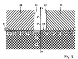
- FIG. 9 shows the light distribution on a screen arranged in front of the vehicle. On the screen a vertical VV and a horizontal HH are drawn. The light distribution is designated by the reference numeral 10. The drawn in the light distribution 10 lines 11 are so-called. Isoluxlinien that identify areas of equal illuminance. A region 12 of the light distribution 10 with the greatest illuminance is horizontal at approximately 0 ° for a light module in a horizontal zero position. In the FIG. 9 shown light distribution 10 has been pivoted by about 4 ° -5 ° to the left. Consequently, in the illustrated embodiment, the area 12 having the greatest illuminance is about 4 ° to 5 ° left of the vertical VV and about 1 ° to 2 ° below the horizontal HH.
- the light distribution 10 comprises a basic light distribution, which is bounded above by a substantially horizontal light-dark boundary 13.
- the light-dark boundary 13 is formed symmetrically, that is, it has both on the own traffic side as well as on the opposite side in about the same horizontal course.
- the light-dark boundary 13 could also be formed asymmetrically, with a section of the light-dark boundary 13 on the own traffic side then being arranged above a section on the oncoming traffic side.
- the transition between the two sections can be stepwise or otherwise, for example. By means of a rising at an angle of 15 ° section occur.
- the illustrated basic light distribution extends in the horizontal direction from about -40 ° to + 40 ° and in the vertical direction from about -13 ° to about -1 °.
- the light distribution 10 additionally comprises a lighted area 14 which is arranged above the light-dark boundary 13 and which is bounded laterally at least in regions by approximately vertically extending light-dark boundaries.
- the lateral light-dark boundaries run essentially vertically toward the basic light distribution and are bent inwards towards the top so that the region 14 has the shape of a semicircle at the top.
- the shape of the area 14 may differ in practice from the illustrated shape. It is important, however, that the region 14 has an extent of only a few degrees both in the horizontal and in the vertical direction.
- the width is determined by a point where the gradient of the brightness distribution exceeds a certain value, preferably has a maximum, measured on the left side of the region 14, to a corresponding point on the right side of the region 14.
- the aforementioned points are usually located at the left dark-light transition or at the right light-dark transition of the region 14.
- the region 14 has a width b of about 2 ° and a height h of about 3 °.
- the area 14 is arranged above the area 12 of the basic illumination with the highest illuminance. In a light module in horizontal zero position, the area 14 is approximately at the vertical VV. Due to the pivoting of the light distribution 10 in FIG. 9 generating module by about 4 ° -5 ° to the left is also the range 14 in the illustrated embodiment about 4 ° -5 ° left of the vertical VV.
- the light distribution 10 may also be designed differently.
- the region 12 of the greatest illuminance in the horizontal zero position of the light module is not arranged on the vertical but laterally offset from it.
- the illuminated area 14 above the light-dark boundary 13 which could also be arranged laterally offset to the vertical in the horizontal zero position of the module.
- FIG. 2 an example of a arranged on the opposite side of the headlight 2 of the vehicle 1 is shown.
- the headlight 2 comprises a housing 21 which is open in the light exit direction 20.
- the opening of the housing 21 is closed by a transparent cover disk 22.
- the cover 22 may be partially formed with or without optically active elements (eg prisms). It consists of transparent plastic or glass.
- Inside the housing 21 at least one light module 23, 24 is arranged inside the housing 21 .
- two light modules 23, 24 are provided inside the housing 21 .
- the one light module 24 for generating a basic light distribution which causes a particularly wide illumination of the road ahead of the vehicle
- the other light module 23 for generating a spot light distribution which concentrates in a central region of the light distribution 10 may be formed.
- the basic light distribution extends in FIG. 9 For example, in the horizontal direction from -40 ° to + 40 ° and in the vertical direction from -13 ° to -1 °.
- the spotlight distribution extends, for example, from -10 ° to + 2 ° and in the vertical direction from -4 ° to -1 °.
- the spotlight distribution may have an extension deviating from the values given by way of example.
- a superposition of the two partial light distributions generates the light distribution 10.
- the in FIG. 9 shown light distribution by a single light module, for example, the light module 23 alone, are generated.
- the module 23 is designed as a projection module. It has a light source 30, which may be formed, for example, as an incandescent lamp, a gas discharge lamp, a light outcoupling surface of a light guide, or as at least one semiconductor light source (LEDs).
- the light emitted by the light source 30 is focused by a primary optics 31, which in the illustrated embodiment as a reflector, preferably as an ellipsoidal or free-form reflector is formed.
- a primary optics 31 which in the illustrated embodiment as a reflector, preferably as an ellipsoidal or free-form reflector is formed.
- the light source comprises LEDs - as a transparent optical element, which bundles the emitted light by total reflection.
- a diaphragm arrangement 32 is arranged in the beam path, which shadows a part of the collimated light.
- the diaphragm arrangement 32 extends in a substantially vertical plane perpendicular to an optical axis 33 of the module 23 and below the optical axis 33.
- a secondary optics 34 is arranged in the beam path, which in the illustrated embodiment is a projection lens is trained.
- the lens 34 is fixed by means of a holding frame 35 at the front edge of the reflector 31.
- the projection lens 34 projects the light which has passed the diaphragm arrangement 32 onto the road ahead of the vehicle 1.
- an upper edge 36 of the diaphragm arrangement 32 is projected onto the roadway as a light-dark boundary 13.
- the upper edge 36 has a light-dark boundary 13 corresponding course.
- the entire projection module 23 is pivotable about a vertical axis of rotation 37.
- the curve light function can also be achieved by only parts of the module 23, for example, the lens 34, are pivoted.
- the Blend assembly 32 includes a plurality of aperture elements 40, 41. In the illustrated embodiment, only two aperture elements 40, 41 are provided. These extend in a substantially transverse to the optical axis 33 of the light module 23 extending vertical plane.
- the diaphragm elements are movably mounted about an axis of rotation 42 extending essentially parallel to the optical axis 33.
- Each panel element 40, 41 has a guide slot 43, 44, which are preferably designed differently. In the scenes 43, 44 engages a guide pin 45 of an actuator 46 a.
- the guide pin 45 is arranged eccentrically on a rotatable about a rotation axis 47 wheel 48.
- the axis of rotation 47 preferably runs parallel to the axis of rotation 42 of the diaphragm elements 40, 41 and to the optical axis 33 of the light module 23.
- the diaphragm elements 40, 41 have upper edges 49, 50 with preferably different contours.
- the actuator 46 By actuating the actuator 46, the guide pin 45 is moved in the scenes 43, 44. Since the axes of rotation 42, 47 are fixed, a movement of the pin 45 in the scenes 43, 44 leads to a pivoting movement 51 of the diaphragm elements 40, 41 about the axis of rotation 42.
- the arranged in the beam path effective upper edge of the entire diaphragm assembly 32 results from a superposition of the Upper edges 49, 50 of the two diaphragm elements 40, 41.
- a slot 52 is formed, which serves to generate the above the light-dark boundary 13 arranged illuminated area 14 of the light distribution 10.
- the area 14 is created solely by the slot 52 in the top edge 49.
- the region 14 it would also be conceivable for the region 14 to be produced by an interaction of the two upper edges 49, 50 of the diaphragm elements 40, 41.
- the upper edge 50 By raising the diaphragm element 41 relative to the diaphragm element 40, for example, the upper edge 50 could be raised beyond a substantially horizontal bottom section 52 'of the slot 52, so that the upper edge 50 determines the height h of the illuminated region 14 above the light-dark boundary 13. This would also allow a dynamic variation of the height h of the region 14.
- the region 14 above the light-dark boundary 13 of the light distribution 10 can be pivoted in the horizontal direction.
- the illuminated area 14 can be targeted to objects detected in front of the vehicle 1.
- the attention of the driver is thus particularly focused on the potentially hazardous objects.
- the detected objects are thus emphasized in the real existing environment and not on any representation (eg on a screen) or projection (eg on the windshield or a transparent body in the field of vision of the driver) Environment.
- the driver can always direct his entire attention to the road ahead of his vehicle 1 and does not have to turn his eyes to look at screens, projections or warning lights.
- the present invention thus results in a decisive gain in safety for the driver as well as the detected objects, without this causing other road users to be dazzled or endangered in any other way.
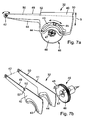
- FIG. 4 another example of the light module 23 is shown.
- the module 23 is very similar to that in FIG. 3 shown module. Corresponding components have been designated by the same reference numerals.
- the module 23 off FIG. 4 is different from the one in FIG. 3 shown in particular by the design and operation of the shutter assembly 32 '.
- the diaphragm arrangement 32 ' is designed as a free-form roller, on whose lateral surface different upper edges 36' are formed with different contour curves.
- the roller is rotatable about a transverse to the optical axis 33 of the light module 23 and approximately horizontally extending axis of rotation 38.
- an actuator 39 comprising an electric motor 39', in particular a stepper motor, driven by this worm 39 "and a driven by the worm gear 39"', which rotatably with the roller 32' is in communication .
- an electric motor 39' in particular a stepper motor
- the diaphragm arrangement 32 ' By turning the diaphragm arrangement 32 ', one of the upper edges 36' can be moved as an effective upper edge into the beam path of the module 23.
- the effective upper edge 36 ' is then projected by the projection lens 34 as a light-dark boundary on the road ahead of the motor vehicle.
- the reference numeral 32 " is in FIG. 4 a symbolic representation of the freeform roller 32 'to illustrate their operation reproduced.
- four different diaphragm elements with upper edges 36" are arranged with different contour curves.
- the individual diaphragm elements or their upper edges 36 '' are circumferentially spaced approximately 90 ° from each other
- the upper edges 36 '' of the symbolic representation of the roller 32 ' all have a horizontal course, with which a symmetrical light-dark boundary could be created
- Such an embodiment of a freeform roller 32 " is, for example, in FIG. 6 shown.
- the individual panel elements are designated by the reference numeral 60. These may - in deviation from the illustrated embodiment - also be an integral part of the roller body 61. They have upper edges 36 'with different contour curves.
- This in FIG. 6 Downwardly facing diaphragm element 60 is used to produce a conventional low-beam asymmetrical light distribution, as is customary in Europe. Therefore, the lower panel member has a horizontal portion on the left side and on the right side at an angle of about 15 ° sloping portion.
- the upward-facing diaphragm element 60 is in the beam path of the light module 23 from FIG. 4 arranged and therefore forms the so-called. Effective upper edge 36 '.
- the Top edge 36 'of the upper aperture element 60 is for generating the in FIG.
- FIG. 5 A third embodiment of a light module 23 is shown in FIG FIG. 5 in a view from the front, that is opposite to the light exit direction 20 shown.
- This module 23 comprises a combination of reflection and projection module.
- As light sources LEDs 70, 71 are used. These are arranged on a heat sink 72.
- first LEDs 70 are arranged on the top and the bottom of the heat sink 72 .
- the light emitted by these light is reflected by primary optics in the form of half-shell reflectors 73 in the light exit direction 20.
- the LEDs 70 and the reflectors 73 form a reflection module of the light module 23.
- the reflection module can produce a broad base light distribution that is similar or equal to the light distribution generated by the second light module 24 of the headlight 2.
- LEDs 71 are arranged on the front of the heat sink 72 .
- the light emitted by these light is focused by a primary optics in the form of intent optics 74 of a transparent material with total reflective properties.
- the collimated light is from a secondary optics in the form of a projection lens 75 in Light exit direction 20 projected.
- the LEDs 71, the front optics 74 and the lens 75 form a projection module of the light module 23.
- the projection module can generate a spot light distribution. A superimposition of the basic light distribution of the reflection module and the spotlight distribution results in the desired resulting light distribution of the module 23.
- a diaphragm arrangement for realizing an effective upper edge is provided, which is suitable for producing a dimmed light distribution 10 with symmetrical or asymmetric light-dark boundary 13 with a light-dark boundary 13 arranged above the illuminated area 14.
- the entire module 23 or parts thereof, for example, the projection lens 75 can be pivoted about the vertical axis of rotation 37, so that the illuminated area 14 can be pivoted in the horizontal direction and can be targeted to objects detected in front of the vehicle 1.
- the diaphragm arrangement is designed such that it can generate at least conventional asymmetrical dipped beam, high street lighting, high beam and a partial high beam distribution 80 on its own traffic side. In addition, it can still generate highway or city light.
- the dimmed light distribution 10 with the above the light-dark boundary 13 arranged illuminated area 14 is not generated by the headlight 3.
Landscapes
- Engineering & Computer Science (AREA)
- General Engineering & Computer Science (AREA)
- Mechanical Engineering (AREA)
- Non-Portable Lighting Devices Or Systems Thereof (AREA)
- Lighting Device Outwards From Vehicle And Optical Signal (AREA)
Claims (14)
- Module de lumière (23) pour un phare de véhicule automobile (2) pour la génération d'une diffusion de lumière adaptative, le module de lumière (23) comprenant :- au moins une source de lumière (30 ; 70, 71) pour l'émission de lumière,- au moins une optique primaire (31 ; 73, 74) pour la concentration de la lumière émise,- un agencement de diaphragme (32 ; 32') pour la réalisation d'une arête supérieure (36 ; 36') active et variable qui peut être introduite dans une trajectoire de faisceau de la lumière émise et/ou concentrée, et- une optique secondaire (34 ; 75), de préférence sous la forme d'une lentille de projection pour la projection de la lumière parvenant devant l'arête supérieure (36 ; 36') active de l'agencement de diaphragme (32 ; 32') sur une chaussée devant le véhicule (1), l'agencement de diaphragme (32 ; 32') étant réalisé pour la réalisation d'une arête supérieure (36 ; 36') active, laquelle provoque la génération d'une diffusion de lumière (10) en code avec la limite clair-obscur sensiblement horizontale (13) et avec une zone (14) éclairée réalisée sur une position horizontale déterminée au-dessus de la limite clair-obscur (13), laquelle zone est délimitée à droite et à gauche par des limites clair-obscur et présente sur un écran de mesure pouvant être agencé à distance devant le phare une étendue dans le sens horizontal et vertical de respectivement quelques degrés, caractérisé en ce que le module de lumière (23) comporte des moyens pour le pivotement horizontal du module de lumière (23) ou d'une partie (75) de celui-ci afin de diriger la zone éclairée (14) au-dessus de la limite clair-obscur horizontale (13) sur des objets détectés devant le véhicule (1) de manière ciblée.
- Module de lumière (23) selon la revendication 1, caractérisé en ce que la zone éclairée (14) est délimitée à droite et gauche au moins en partie par des limites clair-obscur verticales.
- Module de lumière (23) selon la revendication 1 ou 2, caractérisé en ce que la zone éclairée (14) au-dessus de la limite clair-obscur (13) horizontale présente une étendue d'environ 2° horizontalement et d'environ 3 à 5° verticalement.
- Module de lumière (23) selon l'une quelconque des revendications précédentes, caractérisé en ce que les moyens pour le pivotement horizontal du module de lumière (23) sont prévus pour la réalisation d'une fonction d'éclairage en virage dynamique du phare (2).
- Module de lumière (23) selon l'une quelconque des revendications 1 à 4, caractérisé en ce que l'agencement de diaphragme (32 ; 32') présente un rouleau (32' ; 61) rotatif autour d'un axe de rotation (38) horizontal, s'étendant transversalement à l'axe optique (33), sur la surface enveloppe duquel plusieurs arêtes supérieures (36') s'étendant transversalement à l'axe optique (33), espacées les unes des autres sont réalisées avec différents développements, l'une des arêtes supérieures formant l'arête supérieure (36') active pour la génération de la diffusion de lumière en code (10) avec la zone (14) éclairée prévue au-dessus de la limite clair-obscur (13).
- Module de lumière (23) selon l'une quelconque des revendications 1 à 4, caractérisé en ce que l'agencement de diaphragme (32 ; 32') présente plusieurs éléments de diaphragme (40, 41) mobiles l'un par rapport à l'autre autour d'un axe de rotation (42) horizontal agencé parallèlement à l'axe optique (33) et s'étendant sensiblement transversalement à l'axe optique (33), l'une des arêtes supérieures (49) ou plusieurs arêtes supérieures (49, 50) formant par recouvrement l'arête supérieure (36) active pour la génération de la diffusion de lumière en code (10) avec la zone (14) éclairée prévue au-dessus de la limite clair-obscur (13).
- Module de lumière (23) selon l'une quelconque des revendications 1 à 6, caractérisé en ce que l'au moins une source de lumière comporte une ou plusieurs sources de lumière à semi-conducteur (70, 71).
- Module de lumière (23) selon la revendication 7, caractérisé en ce que l'au moins une optique primaire présente un ou plusieurs éléments actifs optiquement (74) qui concentrent la lumière émise par réflexion totale.
- Phare de véhicule automobile (2) avec un module de lumière (23) pour la génération d'une diffusion de lumière adaptative, le module de lumière (23) comprenant- au moins une source de lumière (30 ; 70, 71) pour l'émission de lumière,- au moins une optique primaire (31 ; 73, 74) pour la concentration de la lumière émise,- un agencement de diaphragme (32 ; 32') pour la réalisation d'une arête supérieure (36 ; 36') active et variable qui peut être introduite dans une trajectoire de faisceau de la lumière émise et/ou concentrée et- une optique secondaire (34 ; 75) de préférence sous la forme d'une lentille de projection pour la projection de la lumière parvenant devant l'arête supérieure active (36 ; 36') de l'agencement de diaphragme (32 ; 32') sur une chaussée devant le véhicule (1), l'agencement de diaphragme (32 ; 32') étant réalisé pour la réalisation d'une arête supérieure (36, 36') active, laquelle provoque la génération d'une diffusion de lumière (10) en code avec une limite clair-obscur (13) sensiblement horizontale et avec une zone (14) éclairée réalisée sur une position horizontale déterminée au-dessus de la limite clair-obscur (13), laquelle zone est délimitée à droite et gauche par des limites clair-obscur et présente sur un écran de mesure agencé à distance devant le phare (2) une étendue dans le sens horizontal et vertical de respectivement quelques degrés, caractérisé en ce que le module de lumière (23) comporte des moyens pour le pivotement horizontal du module de lumière (23) ou d'une partie (75) de celui-ci afin de diriger la zone éclairée (14) au-dessus de la limite clair-obscur (13) horizontale sur des objets détectés devant le véhicule (1) de manière ciblée.
- Phare de véhicule automobile (2) selon la revendication 9, caractérisé en ce que le module de lumière (23) est réalisé pour la réalisation d'une fonction de lumière concentrée et le phare (2) présente un autre module de lumière (24) pour la réalisation d'un éclairage de base, les deux modules de lumière (23, 24) formant ensemble la diffusion de lumière en code (10).
- Système de phare pour un véhicule automobile (1) pour l'éclairage d'une chaussée devant le véhicule automobile avec une diffusion de lumière adaptative, le système de phare comprenant à l'avant du véhicule (1) respectivement au moins un phare de véhicule automobile (3) sur le propre côté de circulation et un phare (2) sur le côté de circulation antagoniste, des moyens (5) pour la détection d'une projection d'une zone devant le véhicule (1) et des moyens (6) pour l'évaluation de la projection détectée pour la détection d'objets devant le véhicule (1), au moins l'un des phares (2, 3) présentant au moins un module de lumière (23, 24) pour la génération d'une diffusion de lumière adaptative, le module de lumière (23 ; 24) comprenant- au moins une source de lumière (30 ; 70, 71) pour l'émission de lumière,- au moins une optique primaire (31 ; 73, 74) pour la concentration de la lumière émise,- un agencement de diaphragme (32 ; 32') pour la réalisation d'une arête supérieure (36 ; 36') active et variable qui peut être introduite dans une trajectoire de faisceau de la lumière émise et/ou concentrée et- une optique secondaire (34 ; 75) de préférence sous la forme d'une lentille de projection pour la réalisation de la lumière parvenant devant l'arête supérieure active (36 ; 36') de l'agencement de diaphragme (32 ; 32') sur une chaussée devant le véhicule (1), l'agencement de diaphragme (32 ; 32') au moins d'un des modules de lumière (23) d'au moins un phare (2) étant réalisé pour la réalisation d'une arête supérieure (36, 36') active, laquelle provoque la génération d'une diffusion de lumière (10) en code avec une limite clair-obscur (13) sensiblement horizontale et avec une zone (14) éclairée réalisée sur une position horizontale déterminée au-dessus de la limite clair-obscur (13), laquelle zone est délimitée à droite et gauche par des limites clair-obscur et présente sur un écran de mesure agencé à distance devant le phare (2) une étendue dans le sens horizontal et vertical de respectivement quelques degrés, caractérisé en ce qu'au moins un des modules de lumière (23, 24) comporte des moyens pour le pivotement horizontal de l'au moins un module de lumière (23, 24) ou d'une partie (75) de celui-ci afin de diriger la zone éclairée (14) au-dessus de la limite clair-obscur (13) horizontale sur des objets détectés devant le véhicule (1) de manière ciblée.
- Système de phare selon la revendication 11, caractérisé en ce que seul le phare (2) agencé sur le côté de circulation antagoniste présente un module de lumière (23) avec un agencement de diaphragme (32 ; 32') qui est réalisé pour la réalisation d'une arête supérieure (36 ; 36') qui provoque la génération de la diffusion de lumière en code (10) avec la zone (14) éclairée réalisée au-dessus de la limite clair-obscur (13).
- Système de phare selon la revendication 11 ou 12, caractérisé en ce que les moyens (5) pour la détection de la projection d'une zone devant le véhicule (1) sont réalisés comme une caméra, de préférence comme une caméra (5) qui détecte la projection par réception et traitement d'un rayonnement infrarouge invisible.
- Système de phare selon la revendication 13, caractérisé en ce que la caméra (5) fait partie d'un système de vision nocturne du véhicule (1) qui présente au conducteur du véhicule (1) la projection détectée à l'aide de la caméra (5) de la zone devant le véhicule (1) à l'aide d'un écran ou d'une projection sur un pare-brise du véhicule (1).
Applications Claiming Priority (1)
| Application Number | Priority Date | Filing Date | Title |
|---|---|---|---|
| DE102009035743A DE102009035743A1 (de) | 2009-08-01 | 2009-08-01 | Lichtmodul für einen Kraftfahrzeugscheinwerfer |
Publications (3)
| Publication Number | Publication Date |
|---|---|
| EP2280220A2 EP2280220A2 (fr) | 2011-02-02 |
| EP2280220A3 EP2280220A3 (fr) | 2012-01-18 |
| EP2280220B1 true EP2280220B1 (fr) | 2016-07-13 |
Family
ID=42752290
Family Applications (1)
| Application Number | Title | Priority Date | Filing Date |
|---|---|---|---|
| EP10004955.0A Not-in-force EP2280220B1 (fr) | 2009-08-01 | 2010-05-11 | Module de lumière pour un phare de véhicule automobile |
Country Status (4)
| Country | Link |
|---|---|
| US (1) | US8465187B2 (fr) |
| EP (1) | EP2280220B1 (fr) |
| CN (1) | CN101988666B (fr) |
| DE (1) | DE102009035743A1 (fr) |
Families Citing this family (17)
| Publication number | Priority date | Publication date | Assignee | Title |
|---|---|---|---|---|
| DE102009054227A1 (de) * | 2009-11-21 | 2011-05-26 | Volkswagen Ag | Verfahren zum Steuern einer Scheinwerferanordnung für ein Fahrzeug und Scheinwerferanordnung |
| DE202010006097U1 (de) | 2009-12-22 | 2010-08-05 | Automotive Lighting Reutlingen Gmbh | Lichtmodul für einen Kraftfahrzeugscheinwerfer |
| DE102010013558A1 (de) * | 2010-03-31 | 2011-10-06 | Hella Kgaa Hueck & Co. | Projektionsscheinwerferanordnung für Fahrzeuge |
| DE102010045435B4 (de) * | 2010-09-15 | 2019-10-10 | HELLA GmbH & Co. KGaA | Projektionsscheinwerfer für Fahrzeuge |
| DE102011075510A1 (de) * | 2011-05-09 | 2012-11-15 | Automotive Lighting Reutlingen Gmbh | Lichtmodul für einen Kraftfahrzeugscheinwerfer zur Erzeugung einer variablen Lichtverteilung und Kraftfahrzeugscheinwerfer mit einem solchen Lichtmodul |
| JP2013058375A (ja) * | 2011-09-08 | 2013-03-28 | Koito Mfg Co Ltd | 車輌用前照灯 |
| DE102012013730A1 (de) | 2012-07-11 | 2014-01-16 | GM Global Technology Operations LLC (n. d. Gesetzen des Staates Delaware) | Scheinwerfersystem für ein Kraftfahrzeug |
| DE102013204063B4 (de) * | 2013-03-08 | 2023-03-16 | Automotive Lighting Reutlingen Gmbh | Scheinwerfer eines Kraftfahrzeugs zur Erzeugung von Lichtverteilungen |
| DE102013219095A1 (de) * | 2013-09-23 | 2015-03-26 | Hella Kgaa Hueck & Co. | Verfahren zur Steuerung einer Lichtverteilung eines Scheinwerfers und Scheinwerfer hierfür |
| JP6261276B2 (ja) * | 2013-10-11 | 2018-01-17 | 株式会社小糸製作所 | 車両用灯具 |
| FR3026687B1 (fr) * | 2014-10-02 | 2018-03-02 | Valeo Vision | Systeme d'eclairage a profil d'intensite optimise pour projecteur de vehicule automobile |
| KR101610535B1 (ko) * | 2014-11-04 | 2016-04-20 | 현대자동차주식회사 | 적응형 전조등 시스템의 빔 패턴 조절 장치 |
| DE102014017978A1 (de) | 2014-12-04 | 2016-06-09 | Audi Ag | Beleuchtungsvorrichtung für ein Kraftfahrzeug, Kraftfahrzeug mit einer Beleuchtungsvorrichtung und Verfahren zum Betreiben einer Beleuchtungsvorrichtung |
| CN106166980A (zh) * | 2015-05-22 | 2016-11-30 | 福特全球技术公司 | 用于控制前照灯的方法和装置 |
| CN108375033A (zh) * | 2016-11-18 | 2018-08-07 | 北京汽车股份有限公司 | Led近光模组以及车辆 |
| DE102017202466B4 (de) * | 2017-02-15 | 2019-08-08 | Audi Ag | Steuern eines Scheinwerfers eines Kraftfahrzeuges |
| US10990834B2 (en) | 2018-12-13 | 2021-04-27 | GM Global Technology Operations LLC | Method and apparatus for object detection in camera blind zones |
Citations (2)
| Publication number | Priority date | Publication date | Assignee | Title |
|---|---|---|---|---|
| WO2009039882A1 (fr) * | 2007-09-24 | 2009-04-02 | Hella Kgaa Hueck & Co. | Système projecteur pour véhicules |
| WO2011003500A1 (fr) * | 2009-07-07 | 2011-01-13 | Volkswagen Aktiengesellschaft | Phares projecteurs pour un véhicule à moteur |
Family Cites Families (19)
| Publication number | Priority date | Publication date | Assignee | Title |
|---|---|---|---|---|
| DE3802097A1 (de) * | 1988-01-26 | 1989-09-14 | Sassmannshausen Knut | Hohlspiegelleuchte |
| DE4315401A1 (de) * | 1993-05-08 | 1994-11-10 | Bosch Gmbh Robert | Scheinwerfer für Fahrzeuge |
| DE19756437A1 (de) * | 1997-12-18 | 1999-06-24 | Bosch Gmbh Robert | Scheinwerfer für Fahrzeuge für Abblendlicht und Fernlicht |
| AT412994B (de) * | 2000-10-25 | 2005-09-26 | Zizala Lichtsysteme Gmbh | Fahrzeugscheinwerfer |
| FR2827945B1 (fr) * | 2001-07-26 | 2004-02-27 | Valeo Vision | Projecteur elliptique equipe de caches a axes de pivotement transversaux pour vehicule automobile |
| FR2830073B1 (fr) * | 2001-09-27 | 2003-12-12 | Valeo Vision | Projecteur d'eclairage elliptique de vehicule automobile comportant un systeme optique secondaire |
| JP3939529B2 (ja) * | 2001-10-17 | 2007-07-04 | 株式会社小糸製作所 | 車両用前照灯 |
| DE10321435A1 (de) | 2003-05-12 | 2004-12-02 | Hella Kgaa Hueck & Co. | Scheinwerfer für Fahrzeuge und Verfahren zum Herstellen einer Blendenwelle |
| JP4314911B2 (ja) * | 2003-08-20 | 2009-08-19 | スタンレー電気株式会社 | 車両前照灯 |
| DE10340961A1 (de) * | 2003-09-05 | 2005-03-31 | Hella Kgaa Hueck & Co. | Scheinwerfer für Fahrzeuge |
| JP3982504B2 (ja) * | 2004-01-23 | 2007-09-26 | 日産自動車株式会社 | 車両用暗視カメラ装置および表示装置 |
| JP2006202694A (ja) * | 2005-01-24 | 2006-08-03 | Koito Mfg Co Ltd | 車両用前照灯 |
| FR2895782B1 (fr) * | 2006-01-05 | 2013-05-17 | Valeo Vision | Dispositif projecteur elliptique multifonctions avec element optique additionnel |
| DE102006043281B4 (de) * | 2006-09-14 | 2016-05-04 | Volkswagen Ag | Projektionsscheinwerferanordnung für Fahrzeuge |
| DE102007045150B4 (de) * | 2006-09-27 | 2021-03-04 | HELLA GmbH & Co. KGaA | Scheinwerferanordnung für ein Fahrzeug und Verfahren zum Steuern einer Scheinwerferanordnung |
| WO2008037388A2 (fr) * | 2006-09-27 | 2008-04-03 | Volkswagen Aktiengesellschaft | Ensemble phare pour un véhicule et procédé de commande associé |
| DE102007050348A1 (de) | 2007-02-20 | 2008-08-21 | Automotive Lighting Reutlingen Gmbh | Beleuchtungseinrichtung für ein Kraftfahrzeug |
| JP2009283408A (ja) * | 2008-05-26 | 2009-12-03 | Koito Mfg Co Ltd | 車両用前照灯 |
| US8314558B2 (en) * | 2010-01-12 | 2012-11-20 | Ford Global Technologies, Llc | Light emitting diode headlamp for a vehicle |
-
2009
- 2009-08-01 DE DE102009035743A patent/DE102009035743A1/de not_active Withdrawn
-
2010
- 2010-05-11 EP EP10004955.0A patent/EP2280220B1/fr not_active Not-in-force
- 2010-07-28 US US12/845,366 patent/US8465187B2/en not_active Expired - Fee Related
- 2010-07-28 CN CN201010238803.2A patent/CN101988666B/zh not_active Expired - Fee Related
Patent Citations (2)
| Publication number | Priority date | Publication date | Assignee | Title |
|---|---|---|---|---|
| WO2009039882A1 (fr) * | 2007-09-24 | 2009-04-02 | Hella Kgaa Hueck & Co. | Système projecteur pour véhicules |
| WO2011003500A1 (fr) * | 2009-07-07 | 2011-01-13 | Volkswagen Aktiengesellschaft | Phares projecteurs pour un véhicule à moteur |
Also Published As
| Publication number | Publication date |
|---|---|
| EP2280220A2 (fr) | 2011-02-02 |
| CN101988666A (zh) | 2011-03-23 |
| EP2280220A3 (fr) | 2012-01-18 |
| DE102009035743A1 (de) | 2011-02-17 |
| US8465187B2 (en) | 2013-06-18 |
| US20110025849A1 (en) | 2011-02-03 |
| CN101988666B (zh) | 2016-01-06 |
Similar Documents
| Publication | Publication Date | Title |
|---|---|---|
| EP2280220B1 (fr) | Module de lumière pour un phare de véhicule automobile | |
| DE102009057219B4 (de) | Vorrichtung zur Steuerung eines Fahrlichts eines Fahrzeugs | |
| EP2492580B1 (fr) | Dispositif d'éclairage prévu pour l'intégration dans un véhicule automobile | |
| EP2518397B1 (fr) | Phare de véhicule avec un module de base et un module spot pour produire un faisceau de route et système de phare correspondant | |
| DE102009010558B4 (de) | Lichtmodul für einen Scheinwerfer eines Kraftfahrzeugs und Kraftfahrzeugscheinwerfer mit einem solchen Lichtmodul | |
| DE102008053945B4 (de) | Verfahren zum Steuern einer Scheinwerferanordnung für ein Fahrzeug und Scheinwerferanordnung hierfür | |
| DE102011078653B4 (de) | Vorsatzoptik zur Bündelung von ausgesandtem Licht mindestens einer Halbleiterlichtquelle | |
| EP2523022B1 (fr) | Module d'éclairage pour un phare de véhicule automobile destiné à la production d'une distribution lumineuse variable et phare de véhicule automobile doté d'un tel module d'éclairage | |
| DE19961942B4 (de) | Scheinwerferanlage für Fahrzeuge zur Erzeugung von Lichtbündeln mit unterschiedlicher Charakteristik | |
| EP2338729A1 (fr) | Module de lumière pour un phare de véhicule automobile | |
| DE102007028658A1 (de) | Verfahren zum Steuern einer Scheinwerferanordnung für ein Fahrzeug mit separaten Scheinwerfern für ein Abblendlicht und ein Fernlicht | |
| DE102008036193A1 (de) | Beleuchtungseinrichtung für ein Kraftfahrzeug | |
| DE19860669A1 (de) | Scheinwerfer für Fahrzeuge nach dem Projektionsprinzip | |
| EP2553325B1 (fr) | Système projecteur pour véhicules | |
| DE202010002800U1 (de) | Beleuchtungseinrichtung für ein Kraftfahrzeug | |
| EP2284439A2 (fr) | Phare avant doté d'un module à LED pour éclairage de type route partiel | |
| DE102007022245B4 (de) | Scheinwerfer für Fahrzeuge | |
| WO2014206625A1 (fr) | Phare de motocycle | |
| EP2402647B1 (fr) | Module d'éclairage pour un phare de véhicule automobile | |
| DE102013202370B4 (de) | Lichtmodul für ein Kraftfahrzeug | |
| AT500562B1 (de) | Fahrzeugscheinwerfer |
Legal Events
| Date | Code | Title | Description |
|---|---|---|---|
| PUAI | Public reference made under article 153(3) epc to a published international application that has entered the european phase |
Free format text: ORIGINAL CODE: 0009012 |
|
| AK | Designated contracting states |
Kind code of ref document: A2 Designated state(s): AL AT BE BG CH CY CZ DE DK EE ES FI FR GB GR HR HU IE IS IT LI LT LU LV MC MK MT NL NO PL PT RO SE SI SK SM TR |
|
| AX | Request for extension of the european patent |
Extension state: BA ME RS |
|
| PUAL | Search report despatched |
Free format text: ORIGINAL CODE: 0009013 |
|
| AK | Designated contracting states |
Kind code of ref document: A3 Designated state(s): AL AT BE BG CH CY CZ DE DK EE ES FI FR GB GR HR HU IE IS IT LI LT LU LV MC MK MT NL NO PL PT RO SE SI SK SM TR |
|
| AX | Request for extension of the european patent |
Extension state: BA ME RS |
|
| RIC1 | Information provided on ipc code assigned before grant |
Ipc: F21V 14/08 20060101AFI20111215BHEP |
|
| 17P | Request for examination filed |
Effective date: 20120718 |
|
| 17Q | First examination report despatched |
Effective date: 20130607 |
|
| RIN1 | Information on inventor provided before grant (corrected) |
Inventor name: ROSENHAHN, ERNST-OLAF Inventor name: STAUSS, BENJAMIN Inventor name: BUCHBERGER, CHRISTIAN |
|
| RIN1 | Information on inventor provided before grant (corrected) |
Inventor name: STAUSS, BENJAMIN Inventor name: ROSENHAHN, ERNST-OLAF Inventor name: BUCHBERGER, CHRISTIAN |
|
| RIN1 | Information on inventor provided before grant (corrected) |
Inventor name: STAUSS, BENJAMIN Inventor name: ROSENHAHN, ERNST-OLAF Inventor name: BUCHBERGER, CHRISTIAN |
|
| REG | Reference to a national code |
Ref country code: DE Ref legal event code: R079 Ref document number: 502010011980 Country of ref document: DE Free format text: PREVIOUS MAIN CLASS: F21V0014080000 Ipc: F21S0008100000 |
|
| RIC1 | Information provided on ipc code assigned before grant |
Ipc: F21S 8/10 20060101AFI20151208BHEP |
|
| GRAP | Despatch of communication of intention to grant a patent |
Free format text: ORIGINAL CODE: EPIDOSNIGR1 |
|
| INTG | Intention to grant announced |
Effective date: 20160205 |
|
| GRAS | Grant fee paid |
Free format text: ORIGINAL CODE: EPIDOSNIGR3 |
|
| GRAA | (expected) grant |
Free format text: ORIGINAL CODE: 0009210 |
|
| AK | Designated contracting states |
Kind code of ref document: B1 Designated state(s): AL AT BE BG CH CY CZ DE DK EE ES FI FR GB GR HR HU IE IS IT LI LT LU LV MC MK MT NL NO PL PT RO SE SI SK SM TR |
|
| REG | Reference to a national code |
Ref country code: GB Ref legal event code: FG4D Free format text: NOT ENGLISH |
|
| REG | Reference to a national code |
Ref country code: AT Ref legal event code: REF Ref document number: 812640 Country of ref document: AT Kind code of ref document: T Effective date: 20160715 Ref country code: CH Ref legal event code: EP |
|
| REG | Reference to a national code |
Ref country code: IE Ref legal event code: FG4D Free format text: LANGUAGE OF EP DOCUMENT: GERMAN |
|
| REG | Reference to a national code |
Ref country code: DE Ref legal event code: R096 Ref document number: 502010011980 Country of ref document: DE |
|
| REG | Reference to a national code |
Ref country code: LT Ref legal event code: MG4D |
|
| REG | Reference to a national code |
Ref country code: NL Ref legal event code: MP Effective date: 20160713 |
|
| PG25 | Lapsed in a contracting state [announced via postgrant information from national office to epo] |
Ref country code: IT Free format text: LAPSE BECAUSE OF FAILURE TO SUBMIT A TRANSLATION OF THE DESCRIPTION OR TO PAY THE FEE WITHIN THE PRESCRIBED TIME-LIMIT Effective date: 20160713 Ref country code: LT Free format text: LAPSE BECAUSE OF FAILURE TO SUBMIT A TRANSLATION OF THE DESCRIPTION OR TO PAY THE FEE WITHIN THE PRESCRIBED TIME-LIMIT Effective date: 20160713 Ref country code: HR Free format text: LAPSE BECAUSE OF FAILURE TO SUBMIT A TRANSLATION OF THE DESCRIPTION OR TO PAY THE FEE WITHIN THE PRESCRIBED TIME-LIMIT Effective date: 20160713 Ref country code: IS Free format text: LAPSE BECAUSE OF FAILURE TO SUBMIT A TRANSLATION OF THE DESCRIPTION OR TO PAY THE FEE WITHIN THE PRESCRIBED TIME-LIMIT Effective date: 20161113 Ref country code: FI Free format text: LAPSE BECAUSE OF FAILURE TO SUBMIT A TRANSLATION OF THE DESCRIPTION OR TO PAY THE FEE WITHIN THE PRESCRIBED TIME-LIMIT Effective date: 20160713 Ref country code: NL Free format text: LAPSE BECAUSE OF FAILURE TO SUBMIT A TRANSLATION OF THE DESCRIPTION OR TO PAY THE FEE WITHIN THE PRESCRIBED TIME-LIMIT Effective date: 20160713 Ref country code: NO Free format text: LAPSE BECAUSE OF FAILURE TO SUBMIT A TRANSLATION OF THE DESCRIPTION OR TO PAY THE FEE WITHIN THE PRESCRIBED TIME-LIMIT Effective date: 20161013 |
|
| PG25 | Lapsed in a contracting state [announced via postgrant information from national office to epo] |
Ref country code: ES Free format text: LAPSE BECAUSE OF FAILURE TO SUBMIT A TRANSLATION OF THE DESCRIPTION OR TO PAY THE FEE WITHIN THE PRESCRIBED TIME-LIMIT Effective date: 20160713 Ref country code: GR Free format text: LAPSE BECAUSE OF FAILURE TO SUBMIT A TRANSLATION OF THE DESCRIPTION OR TO PAY THE FEE WITHIN THE PRESCRIBED TIME-LIMIT Effective date: 20161014 Ref country code: PT Free format text: LAPSE BECAUSE OF FAILURE TO SUBMIT A TRANSLATION OF THE DESCRIPTION OR TO PAY THE FEE WITHIN THE PRESCRIBED TIME-LIMIT Effective date: 20161114 Ref country code: LV Free format text: LAPSE BECAUSE OF FAILURE TO SUBMIT A TRANSLATION OF THE DESCRIPTION OR TO PAY THE FEE WITHIN THE PRESCRIBED TIME-LIMIT Effective date: 20160713 Ref country code: PL Free format text: LAPSE BECAUSE OF FAILURE TO SUBMIT A TRANSLATION OF THE DESCRIPTION OR TO PAY THE FEE WITHIN THE PRESCRIBED TIME-LIMIT Effective date: 20160713 Ref country code: SE Free format text: LAPSE BECAUSE OF FAILURE TO SUBMIT A TRANSLATION OF THE DESCRIPTION OR TO PAY THE FEE WITHIN THE PRESCRIBED TIME-LIMIT Effective date: 20160713 |
|
| REG | Reference to a national code |
Ref country code: DE Ref legal event code: R097 Ref document number: 502010011980 Country of ref document: DE |
|
| REG | Reference to a national code |
Ref country code: FR Ref legal event code: PLFP Year of fee payment: 8 |
|
| PG25 | Lapsed in a contracting state [announced via postgrant information from national office to epo] |
Ref country code: EE Free format text: LAPSE BECAUSE OF FAILURE TO SUBMIT A TRANSLATION OF THE DESCRIPTION OR TO PAY THE FEE WITHIN THE PRESCRIBED TIME-LIMIT Effective date: 20160713 Ref country code: RO Free format text: LAPSE BECAUSE OF FAILURE TO SUBMIT A TRANSLATION OF THE DESCRIPTION OR TO PAY THE FEE WITHIN THE PRESCRIBED TIME-LIMIT Effective date: 20160713 |
|
| PLBE | No opposition filed within time limit |
Free format text: ORIGINAL CODE: 0009261 |
|
| STAA | Information on the status of an ep patent application or granted ep patent |
Free format text: STATUS: NO OPPOSITION FILED WITHIN TIME LIMIT |
|
| PG25 | Lapsed in a contracting state [announced via postgrant information from national office to epo] |
Ref country code: CZ Free format text: LAPSE BECAUSE OF FAILURE TO SUBMIT A TRANSLATION OF THE DESCRIPTION OR TO PAY THE FEE WITHIN THE PRESCRIBED TIME-LIMIT Effective date: 20160713 Ref country code: SK Free format text: LAPSE BECAUSE OF FAILURE TO SUBMIT A TRANSLATION OF THE DESCRIPTION OR TO PAY THE FEE WITHIN THE PRESCRIBED TIME-LIMIT Effective date: 20160713 Ref country code: SM Free format text: LAPSE BECAUSE OF FAILURE TO SUBMIT A TRANSLATION OF THE DESCRIPTION OR TO PAY THE FEE WITHIN THE PRESCRIBED TIME-LIMIT Effective date: 20160713 Ref country code: BG Free format text: LAPSE BECAUSE OF FAILURE TO SUBMIT A TRANSLATION OF THE DESCRIPTION OR TO PAY THE FEE WITHIN THE PRESCRIBED TIME-LIMIT Effective date: 20161013 Ref country code: DK Free format text: LAPSE BECAUSE OF FAILURE TO SUBMIT A TRANSLATION OF THE DESCRIPTION OR TO PAY THE FEE WITHIN THE PRESCRIBED TIME-LIMIT Effective date: 20160713 |
|
| 26N | No opposition filed |
Effective date: 20170418 |
|
| PG25 | Lapsed in a contracting state [announced via postgrant information from national office to epo] |
Ref country code: SI Free format text: LAPSE BECAUSE OF FAILURE TO SUBMIT A TRANSLATION OF THE DESCRIPTION OR TO PAY THE FEE WITHIN THE PRESCRIBED TIME-LIMIT Effective date: 20160713 Ref country code: LU Free format text: LAPSE BECAUSE OF NON-PAYMENT OF DUE FEES Effective date: 20170531 |
|
| REG | Reference to a national code |
Ref country code: DE Ref legal event code: R079 Ref document number: 502010011980 Country of ref document: DE Free format text: PREVIOUS MAIN CLASS: F21S0008100000 Ipc: F21S0043000000 |
|
| REG | Reference to a national code |
Ref country code: CH Ref legal event code: PL |
|
| GBPC | Gb: european patent ceased through non-payment of renewal fee |
Effective date: 20170511 |
|
| PG25 | Lapsed in a contracting state [announced via postgrant information from national office to epo] |
Ref country code: MC Free format text: LAPSE BECAUSE OF FAILURE TO SUBMIT A TRANSLATION OF THE DESCRIPTION OR TO PAY THE FEE WITHIN THE PRESCRIBED TIME-LIMIT Effective date: 20160713 |
|
| REG | Reference to a national code |
Ref country code: IE Ref legal event code: MM4A |
|
| PG25 | Lapsed in a contracting state [announced via postgrant information from national office to epo] |
Ref country code: CH Free format text: LAPSE BECAUSE OF NON-PAYMENT OF DUE FEES Effective date: 20170531 Ref country code: LI Free format text: LAPSE BECAUSE OF NON-PAYMENT OF DUE FEES Effective date: 20170531 |
|
| PG25 | Lapsed in a contracting state [announced via postgrant information from national office to epo] |
Ref country code: LU Free format text: LAPSE BECAUSE OF NON-PAYMENT OF DUE FEES Effective date: 20170511 |
|
| REG | Reference to a national code |
Ref country code: FR Ref legal event code: PLFP Year of fee payment: 9 |
|
| REG | Reference to a national code |
Ref country code: BE Ref legal event code: MM Effective date: 20170531 |
|
| PG25 | Lapsed in a contracting state [announced via postgrant information from national office to epo] |
Ref country code: GB Free format text: LAPSE BECAUSE OF NON-PAYMENT OF DUE FEES Effective date: 20170511 Ref country code: IE Free format text: LAPSE BECAUSE OF NON-PAYMENT OF DUE FEES Effective date: 20170511 |
|
| PG25 | Lapsed in a contracting state [announced via postgrant information from national office to epo] |
Ref country code: BE Free format text: LAPSE BECAUSE OF NON-PAYMENT OF DUE FEES Effective date: 20170531 |
|
| PG25 | Lapsed in a contracting state [announced via postgrant information from national office to epo] |
Ref country code: MT Free format text: LAPSE BECAUSE OF FAILURE TO SUBMIT A TRANSLATION OF THE DESCRIPTION OR TO PAY THE FEE WITHIN THE PRESCRIBED TIME-LIMIT Effective date: 20160713 |
|
| PG25 | Lapsed in a contracting state [announced via postgrant information from national office to epo] |
Ref country code: AL Free format text: LAPSE BECAUSE OF FAILURE TO SUBMIT A TRANSLATION OF THE DESCRIPTION OR TO PAY THE FEE WITHIN THE PRESCRIBED TIME-LIMIT Effective date: 20160713 |
|
| PG25 | Lapsed in a contracting state [announced via postgrant information from national office to epo] |
Ref country code: HU Free format text: LAPSE BECAUSE OF FAILURE TO SUBMIT A TRANSLATION OF THE DESCRIPTION OR TO PAY THE FEE WITHIN THE PRESCRIBED TIME-LIMIT; INVALID AB INITIO Effective date: 20100511 |
|
| PGFP | Annual fee paid to national office [announced via postgrant information from national office to epo] |
Ref country code: FR Payment date: 20190419 Year of fee payment: 10 |
|
| PG25 | Lapsed in a contracting state [announced via postgrant information from national office to epo] |
Ref country code: CY Free format text: LAPSE BECAUSE OF NON-PAYMENT OF DUE FEES Effective date: 20160713 |
|
| PGFP | Annual fee paid to national office [announced via postgrant information from national office to epo] |
Ref country code: AT Payment date: 20190423 Year of fee payment: 10 |
|
| PG25 | Lapsed in a contracting state [announced via postgrant information from national office to epo] |
Ref country code: MK Free format text: LAPSE BECAUSE OF FAILURE TO SUBMIT A TRANSLATION OF THE DESCRIPTION OR TO PAY THE FEE WITHIN THE PRESCRIBED TIME-LIMIT Effective date: 20160713 |
|
| PG25 | Lapsed in a contracting state [announced via postgrant information from national office to epo] |
Ref country code: TR Free format text: LAPSE BECAUSE OF FAILURE TO SUBMIT A TRANSLATION OF THE DESCRIPTION OR TO PAY THE FEE WITHIN THE PRESCRIBED TIME-LIMIT Effective date: 20160713 |
|
| REG | Reference to a national code |
Ref country code: DE Ref legal event code: R084 Ref document number: 502010011980 Country of ref document: DE |
|
| REG | Reference to a national code |
Ref country code: AT Ref legal event code: MM01 Ref document number: 812640 Country of ref document: AT Kind code of ref document: T Effective date: 20200511 |
|
| PG25 | Lapsed in a contracting state [announced via postgrant information from national office to epo] |
Ref country code: AT Free format text: LAPSE BECAUSE OF NON-PAYMENT OF DUE FEES Effective date: 20200511 |
|
| PG25 | Lapsed in a contracting state [announced via postgrant information from national office to epo] |
Ref country code: FR Free format text: LAPSE BECAUSE OF NON-PAYMENT OF DUE FEES Effective date: 20200531 |
|
| PGFP | Annual fee paid to national office [announced via postgrant information from national office to epo] |
Ref country code: DE Payment date: 20210421 Year of fee payment: 12 |
|
| REG | Reference to a national code |
Ref country code: DE Ref legal event code: R119 Ref document number: 502010011980 Country of ref document: DE |
|
| PG25 | Lapsed in a contracting state [announced via postgrant information from national office to epo] |
Ref country code: DE Free format text: LAPSE BECAUSE OF NON-PAYMENT OF DUE FEES Effective date: 20221201 |