EP2278435A2 - Gant et écran tactile permettant de lire des informations par le toucher - Google Patents
Gant et écran tactile permettant de lire des informations par le toucher Download PDFInfo
- Publication number
- EP2278435A2 EP2278435A2 EP10162171A EP10162171A EP2278435A2 EP 2278435 A2 EP2278435 A2 EP 2278435A2 EP 10162171 A EP10162171 A EP 10162171A EP 10162171 A EP10162171 A EP 10162171A EP 2278435 A2 EP2278435 A2 EP 2278435A2
- Authority
- EP
- European Patent Office
- Prior art keywords
- wall
- glove
- screen
- finger
- touch
- Prior art date
- Legal status (The legal status is an assumption and is not a legal conclusion. Google has not performed a legal analysis and makes no representation as to the accuracy of the status listed.)
- Withdrawn
Links
Images


Classifications
-
- G—PHYSICS
- G06—COMPUTING OR CALCULATING; COUNTING
- G06F—ELECTRIC DIGITAL DATA PROCESSING
- G06F3/00—Input arrangements for transferring data to be processed into a form capable of being handled by the computer; Output arrangements for transferring data from processing unit to output unit, e.g. interface arrangements
- G06F3/01—Input arrangements or combined input and output arrangements for interaction between user and computer
- G06F3/011—Arrangements for interaction with the human body, e.g. for user immersion in virtual reality
- G06F3/014—Hand-worn input/output arrangements, e.g. data gloves
-
- G—PHYSICS
- G06—COMPUTING OR CALCULATING; COUNTING
- G06F—ELECTRIC DIGITAL DATA PROCESSING
- G06F3/00—Input arrangements for transferring data to be processed into a form capable of being handled by the computer; Output arrangements for transferring data from processing unit to output unit, e.g. interface arrangements
- G06F3/01—Input arrangements or combined input and output arrangements for interaction between user and computer
- G06F3/016—Input arrangements with force or tactile feedback as computer generated output to the user
-
- G—PHYSICS
- G06—COMPUTING OR CALCULATING; COUNTING
- G06F—ELECTRIC DIGITAL DATA PROCESSING
- G06F3/00—Input arrangements for transferring data to be processed into a form capable of being handled by the computer; Output arrangements for transferring data from processing unit to output unit, e.g. interface arrangements
- G06F3/01—Input arrangements or combined input and output arrangements for interaction between user and computer
- G06F3/03—Arrangements for converting the position or the displacement of a member into a coded form
- G06F3/033—Pointing devices displaced or positioned by the user, e.g. mice, trackballs, pens or joysticks; Accessories therefor
- G06F3/039—Accessories therefor, e.g. mouse pads
- G06F3/0393—Accessories for touch pads or touch screens, e.g. mechanical guides added to touch screens for drawing straight lines, hard keys overlaying touch screens or touch pads
-
- G—PHYSICS
- G06—COMPUTING OR CALCULATING; COUNTING
- G06F—ELECTRIC DIGITAL DATA PROCESSING
- G06F3/00—Input arrangements for transferring data to be processed into a form capable of being handled by the computer; Output arrangements for transferring data from processing unit to output unit, e.g. interface arrangements
- G06F3/01—Input arrangements or combined input and output arrangements for interaction between user and computer
- G06F3/03—Arrangements for converting the position or the displacement of a member into a coded form
- G06F3/041—Digitisers, e.g. for touch screens or touch pads, characterised by the transducing means
-
- G—PHYSICS
- G06—COMPUTING OR CALCULATING; COUNTING
- G06F—ELECTRIC DIGITAL DATA PROCESSING
- G06F3/00—Input arrangements for transferring data to be processed into a form capable of being handled by the computer; Output arrangements for transferring data from processing unit to output unit, e.g. interface arrangements
- G06F3/01—Input arrangements or combined input and output arrangements for interaction between user and computer
- G06F3/03—Arrangements for converting the position or the displacement of a member into a coded form
- G06F3/041—Digitisers, e.g. for touch screens or touch pads, characterised by the transducing means
- G06F3/044—Digitisers, e.g. for touch screens or touch pads, characterised by the transducing means by capacitive means
- G06F3/0446—Digitisers, e.g. for touch screens or touch pads, characterised by the transducing means by capacitive means using a grid-like structure of electrodes in at least two directions, e.g. using row and column electrodes
-
- G—PHYSICS
- G09—EDUCATION; CRYPTOGRAPHY; DISPLAY; ADVERTISING; SEALS
- G09B—EDUCATIONAL OR DEMONSTRATION APPLIANCES; APPLIANCES FOR TEACHING, OR COMMUNICATING WITH, THE BLIND, DEAF OR MUTE; MODELS; PLANETARIA; GLOBES; MAPS; DIAGRAMS
- G09B21/00—Teaching, or communicating with, the blind, deaf or mute
- G09B21/001—Teaching or communicating with blind persons
- G09B21/003—Teaching or communicating with blind persons using tactile presentation of the information, e.g. Braille displays
Definitions
- the invention relates to a glove and touch screen for pulling information by touch, this glove transmitting in touch form the information provided by the screen, when a user puts this glove and touches the surface of the screen with a finger of this glove.
- a user reads icons or menus on this screen, and enters a command by touching with a finger or a stylus, an area of the screen displaying an icon or a few words.
- To use a touch screen it is necessary to see the screen to know where to touch the screen to enter a given command.
- the user can not see what is displayed on the screen: for example if the device remains in a pocket or bag of the user, or if the user is blind. In these circumstances, the user can not use a touch screen since he does not see the position of the sensitive areas of the screen, and does not see the information displayed in response on the screen.
- the object of the invention is to overcome this disadvantage of touch screens.
- the glove thus characterized makes it possible to perceive information by touch because it applies a pressure variation on a finger of the user when the movement of the finger causes a variation of the electric field applied to the charged microparticles. Indeed, the variation of the electric field applied to the charged microparticles causes a displacement of these microparticles. This displacement causes a pressure variation on the walls of the glove. This pressure variation perceived by touching a screen allows a user to perceive a graphic touch.
- the screen thus characterized makes it possible to transcribe a binary information into a continuous electric field, having a meaning depending on the value of this binary information, on an area of the screen.
- This screen thus provides a kind of electrical image that can activate the glove according to the invention by touching the surface of the screen with a finger.
- a first application of this screen is the graphic display for blind people, including Braille characters.
- a second application concerns people who can see normally, and who want to be able to read information alternately with their eyes and with their fingers.
- the screen comprises at least one transparent electrode, and it further comprises conventional means for displaying an image, through this transparent electrode.
- This screen can also be combined with conventional means for entering commands by touching an area of the screen.
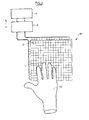
- the figure 1 represents in front view this first embodiment G1 of the glove according to the invention and this first embodiment E1 of the screen according to the invention.
- the user touches one of the electrodes of the touch screen E1 with a finger 1 of the glove G1.
- the surface of the screen E1 comprises a matrix of 16 x 16 electrodes 2 corresponding to 256 zones on the screen.
- a user can thus perceive, by touch, 256 distinct binary values, by touching the screen with a finger 1 of the glove G1.
- the switching circuit 3 has an input connected to the binary information source 5 for receiving the information to be perceived by the touch. It is controlled so as to apply to a given electrode one of the two DC voltages provided by the sources 4.
- the sign of the voltage applied to an electrode 2 is a function of a binary information provided by the information source 5 and corresponding to this electrode, that is to say corresponding to a given area of the screen.
- the binary information source successively supplies 256 binary values corresponding respectively to the 256 electrodes.
- the switching circuit 3 then supplies the 256 voltages continuously, as long as there is no need to display new information.
- the walls 23-24 are made of a dielectric material for transmitting the electric fields between the screen E1 and the finger 28 of the user.
- the walls 23-24 must be sealed at least in the area in contact with the liquid 25.
- they may be rubber, polyethylene, polystyrene, nylon, vinyl, etc.
- the walls 23-24 must be fairly thin, for example a tenth of a millimeter, to allow a good perception of the pressure variations on the finger 28 of the user.
- the microparticles 26-27 are, for example, titanium balls, with a diameter close to one micron.
- the dielectric liquid may be acetone, for example.
- microparticles and fluids usable in electrophoretic display devices are encapsulated in transparent microcapsules. But to achieve the glove according to the invention, there is no encapsulation of the microparticles before introduction between the two walls 23-24.
- the flexible filling material 22 may be neoprene for example.
- the electrodes of the zone 32 of the screen E1 receive a negative voltage, with respect to a reference potential, while the electrodes of the zones 31 and 33 receive a positive voltage.
- the end of the thimble 1 touches the surface of the screen E1 in the zone 32.
- the microparticles 26 -27 which are positively charged, undergo electrostatic forces which move them in the liquid 25: Microparticles 27 are attracted against the outer wall 23 at the end of the thimble 1 because this end is close to the zone 32 where the electrodes receive a negative voltage.
- microparticles 26, located opposite the zones 31 and 32 are pushed against the inner wall 24 and compress a portion of the finger 28 of the user, this portion having approximately the shape of a ring. Consequently, the user feels an increase in pressure around the end of his finger when he passes the zone 32. The user feels a decrease in pressure when he moves his finger 28 out of the zone 32 to touch the zone. 31 or zone 33.
- Each zone used to display an icon or option of a menu is preferably designed to coincide exactly with an electrode, or an integer number of electrodes, of the screen according to the invention, for a user to detect. precisely the position of this icon or this option using the glove according to the invention.
- the size of the screen and if the number of electrodes are sufficient, it is possible to represent a noticeable graphics with the glove according to the invention. In particular, it is possible to perceive a series of pulses similar to the reliefs constituting Braille characters.
- the figure 3 schematically shows in section a finger of a second embodiment of the glove according to the invention. It differs from the second example in that the space, located between the walls 23-24 and containing the microparticles 26-27 has many walls 29 orthogonal to the outer wall 23 and the inner wall 24. They compartmentalize this space. to reduce the displacement of the microparticles in the direction parallel to the outer wall and the wall internal, while leaving them free to move either to the inner wall 24 or to the outer wall 23, in the direction of the electric field.
- these walls 29 constitute braces which maintain a substantially constant spacing between the walls 23-24. They thus maintain an approximately uniform distribution of the microparticles in this space, all around the end of the finger 1.
- the screen comprises only electrodes for transmitting information to a glove according to the invention.
- the electrodes are transparent and are placed in front of a conventional display screen so as to allow to see a conventional display, liquid crystal for example.
- the screen can be used alternately to perceive information by sight or by touch.
- This screen may further comprise means for using it as a conventional touch screen, with or without the glove according to the invention, provided that the glove and these touch control means are adapted to be able to collaborate.
- touch control There are various technologies to achieve touch control. Most of these technologies are compatible with wearing a glove, but not capacitive technology. This uses the existing capacity when the user's finger is very close to an integrated electrode on the screen. This technology generally does not work if the user wears a glove because the thickness of the glove away from the end of the finger relative to the screen.
- a third embodiment of the glove according to the invention makes it possible to use it on a touch screen using capacitive technology.
- the figure 4 schematically shows in section this third embodiment of the glove according to the invention. It differs from the second example in that it comprises a conductive bridge 34, passing through the inner wall 24, the outer wall 23, and the space between these two walls. It has a form of truncated cone. At one end, it is flush with the surface of the wall 23, at the end of the finger 1, and at the other end it is flush with the surface of the inner wall 24. Thus it is in contact with the finger 28 of the user and is in contact with the surface of the screen E1 when the thimble 1 touches the screen E1.
- This conductive bridge has the effect of extending, from the electrical point of view, the end of the finger 28 of the user. This makes it possible to control a touch screen using a capacitive effect and having insufficient sensitivity for operate when the finger 28 of the user is coated with a glove according to the invention for reading information by touch.
- This bridge 34 may consist of a flexible or rigid conductive material, for example a polymer loaded with carbon.
- the electrodes of the screen according to the invention can also constitute electrodes for the conventional function of tactile control by capacitive effect. For example, these two functions can be periodically activated alternately.
- the third exemplary embodiment could further comprise walls compartmentalizing the space containing the microparticles, as in the second example.
- the glove may comprise a plurality of thimbles made as previously described.
- a simplified variant of the glove according to the invention may comprise only one finger and nothing else, the rest of the hand remaining uncovered.
Landscapes
- Engineering & Computer Science (AREA)
- Theoretical Computer Science (AREA)
- General Engineering & Computer Science (AREA)
- Physics & Mathematics (AREA)
- General Physics & Mathematics (AREA)
- Human Computer Interaction (AREA)
- Health & Medical Sciences (AREA)
- Audiology, Speech & Language Pathology (AREA)
- General Health & Medical Sciences (AREA)
- Business, Economics & Management (AREA)
- Educational Administration (AREA)
- Educational Technology (AREA)
- Gloves (AREA)
- Position Input By Displaying (AREA)
- Electronic Switches (AREA)
Abstract
Description
- L'invention concerne un gant et écran tactile permettant de tire des informations par le toucher, ce gant transmettant sous forme tactile des informations que lui fournit l'écran, lorsqu'un usager enfile ce gant et effleure la surface de l'écran avec un doigt de ce gant.
- De nombreux appareils mobiles comportent maintenant un écran tactile constituant une interface graphique pour un usager : Un usager lit des icônes ou des menus sur cet écran, et il entre une commande en touchant avec un doigt ou un stylet, une zone de l'écran affichant une icône ou quelques mots. Pour utiliser un écran tactile il est donc nécessaire de voir l'écran afin de savoir à quel endroit il faut toucher l'écran pour entrer une commande donnée. Cependant, dans certaines circonstances, l'utilisateur ne peut pas voir ce qui est affiché sur l'écran : par exemple si l'appareil reste dans une poche ou un sac de l'utilisateur, ou si l'utilisateur est aveugle. Dans ces circonstances, l'usager ne peut pas utiliser un écran tactile puisqu'il ne voit pas la position des zones sensibles de l'écran, et ne voit pas les informations affichée en réponse sur l'écran.
- Pour aider les aveugles, et les malvoyants, il est connu d'utiliser un logiciel de conversion texte-parole, mais cette solution n'est pas totalement satisfaisante. Un tel logiciel ne sait pas décrire autre chose que du texte : par exemple une icône ou une forme géométrique ne peut pas être directement convertie en paroles. D'autre part, l'énoncé d'un mot affiché n'indique pas la position de ce mot sur l'écran. Cette solution ne permet donc pas de choisir une commande sur un écran tactile puisque l'énoncé d'un mot clef affiché n'indique pas la zone où il faut toucher l'écran.
- Le but de l'invention est de remédier à cet inconvénient des écrans tactiles.
- Un premier objet de l'invention est un gant permettant de lire des informations par le toucher, lorsqu'un doigt de ce gant effleure un écran comportant au moins une zone émettant un champ électrique continu, caractérisé en ce qu'il comporte au moins un doigt de gant comportant :
- une paroi interne souple et diélectrique, apte à recevoir un doigt d'un usager,
- une paroi externe, souple et diélectrique,
- un liquide contenu dans au moins un espace entre ces deux parois,
- et des microparticules placées dans ce liquide, ces microparticules étant électriquement chargées avec une même polarité, et étant aptes à se déplacer dans ce liquide sous l'action d'un champ électrique.
- Le gant ainsi caractérisé permet de percevoir une information par le toucher parce qu'il applique une variation de pression sur un doigt de l'utilisateur lorsque le déplacement du doigt provoque une variation du champ électrique appliqué aux microparticules chargées. En effet, la variation du champ électrique appliqué aux microparticules chargées provoque un déplacement de ces microparticules. Ce déplacement provoque une variation de pression sur les parois du gant. Cette variation de pression perçue en effleurant un écran permet à un usager de percevoir un graphisme par le toucher.
- Un second objet de l'invention est un écran tactile permettant de lire des informations par le toucher, comportant :
- au moins une électrode,
- au moins une source de tension électrique,
- et des moyens de commutation reliés à cette électrode pour créer un champ électrique à partir de cette électrode, ces moyens de commutation étant commandés par une source d'informations ;
- L'écran ainsi caractérisé permet de transcrire une information binaire en un champ électrique continu, ayant un sens fonction de la valeur de cette information binaire, sur une zone de l'écran. Cet écran fournit donc une sorte d'image électrique qui peut activer le gant selon l'invention en effleurant la surface de l'écran avec un doigt.
- Une première application de cet écran est l'affichage de graphisme pour des aveugles, notamment des caractères Braille. Une seconde application concerne les personnes qui peuvent voir normalement, et qui veulent pouvoir lire des informations alternativement avec leurs yeux et avec leurs doigts. Pour cette application, l'écran comporte au moins une électrode transparente, et il comporte en outre des moyens classiques permettant d'afficher une image, à travers cette électrode transparente.
- Cet écran peut en outre être combiné avec des moyens classiques permettant d'entrer des commandes en touchant une zone de l'écran.
- L'invention sera mieux comprise et d'autres caractéristiques apparaîtront à l'aide de la description ci-dessous et des figures l'accompagnant :
- La
figure 1 représente en vue de face un premier exemple de réalisation du gant selon l'invention et un premier exemple de réalisation de l'écran selon l'invention. - La
figure 2 représente schématiquement en coupe ce premier exemple de réalisation de l'écran et un doigt de ce premier exemple de réalisation du gant selon l'invention. - La
figure 3 représente schématiquement en coupe un doigt d'un deuxième exemple de réalisation du gant selon l'invention. - La
figure 4 représente un troisième exemple de réalisation de l'écran selon l'invention. - Les éléments qui sont identiques dans différents exemples de réalisation portent les mêmes références.
- La
figure 1 représente en vue de face ce premier exemple de réalisation G1 du gant selon l'invention et de ce premier exemple de réalisation E1 de l'écran selon l'invention. Dans cet exemple, l'utilisateur effleure une des électrodes de l'écran tactile E1 avec un doigt 1 du gant G1. - L'écran tactile E1 comporte :
- une pluralité électrodes 2 disposées sous la forme d'une matrice,
- deux sources de tension électriques 4 pour fournir une tension positive et une tension négative, par rapport à un potentiel de référence,
- et un circuit de commutation 3 relié à ces deux sources de tensions électriques 4, relié à ces électrodes 2 , et relié à une source d'informations binaires 5.
- Par exemple, la surface de l'écran E1 comporte une matrice de 16 x 16 électrodes 2 correspondant à 256 zones sur l'écran. Un utilisateur peut ainsi percevoir, par le toucher, 256 valeurs binaires distinctes, en effleurant l'écran avec un doigt 1 du gant G1.
- Le circuit de commutation 3 a une entrée reliée à la source d'informations binaires 5 pour recevoir les informations qui devront être perçues par le toucher. Il est commandé de façon à appliquer à une électrode donnée une des deux tensions continues fournies par les sources 4. Le signe de la tension appliquée à une électrode 2 est fonction d'une information binaire fournie par la source d'information 5 et correspondant à cette électrode, c'est-à-dire correspondant à une zone donnée de l'écran.
- Dans cet exemple, la source d'information binaire fournit successivement 256 valeurs binaires correspondant respectivement aux 256 électrodes. Le circuit de commutation 3 fournit ensuite les 256 tensions de manière continue, tant qu'il n'y a pas à afficher de nouvelles informations.
- La
figure 2 représente en coupe le doigt de gant, 1, de ce premier exemple de réalisation du gant selon l'invention, et une partie de ce premier exemple de réalisation E1 de l'écran tactile selon l'invention. Ce doigt de gant 1 comporte : - Une paroi interne souple 24 ayant une élasticité et une taille adaptées pour s'ajuster sur un doigt 28 d'un utilisateur, de façon que l'extrémité du doigt de gant 1 soit parfaitement en contact avec le doigt 28 de l'utilisateur.
- Une paroi externe souple 23 approximativement parallèle à la paroi interne 24 de façon à délimiter un espace d'épaisseur approximativement constante entre les deux parois 23-24.
- Une matière souple 22 remplit cet espace sur la plus grande partie de la longueur du doigt de gant 1, excepté à l'extrémité du doigt 1.
- Un liquide diélectrique 25 remplit tout le reste de cet espace, sur la partie située à l'extrémité du doigt 1.
- Des microparticules 26, 27 sont libres de se déplacer dans ce liquide 28. Elles sont chargées électriquement de manière permanente avec une même polarité, par exemple positive.
- Les parois 23-24 sont réalisées en une matière diélectrique pour transmettre les champs électriques entre l'écran E1 et le doigt 28 de l'utilisateur. En outre, les parois 23-24 doivent être étanches au moins dans la zone en contact avec le liquide 25. Par exemple, elles peuvent être en caoutchouc, polyéthylène, polystyrène, nylon, vinyle, etc. Les parois 23-24 doivent être assez fines, par exemple un dixième de millimètre, pour permettre une bonne perception des variations de pression sur le doigt 28 de l'utilisateur.
- Les microparticules 26-27 sont par exemple des billes de titane, de diamètre voisin d'un micron. Le liquide diélectrique peut être de l'acétone, par exemple.
- On peut utiliser d'autres matériaux qui sont connus pour être utilisés dans les dispositifs d'affichage électrophorétiques. Le document
US 6.262.833 décrit des microparticules et des fluides utilisables dans des dispositifs d'affichage électrophorétiques. Pour les dispositifs d'affichage électrophorétiques, les microbilles sont encapsulées dans des microcapsules transparentes. Mais pour réaliser le gant selon l'invention, il n'y a pas d'encapsulation des microparticules avant leur introduction entre les deux parois 23-24. - La matière souple de remplissage 22 peut être du néoprène par exemple.
- Dans l'exemple représenté, les électrodes de la zone 32 de l'écran E1 reçoivent une tension négative, par rapport à un potentiel de référence, alors que les électrodes des zones 31 et 33 reçoivent une tension positive. L'extrémité du doigt de gant 1 touche la surface de l'écran E1 dans la zone 32. Sous l'action des champs électriques créés par les électrodes de l'écran E1, dans les zones 31,32, 33, les microparticules 26-27, qui sont chargées positivement, subissent des forces électrostatiques qui les déplacent dans le liquide 25 : Des microparticules 27 sont attirées contre la paroi externe 23 à l'extrémité du doigt de gant 1 parce que cette extrémité est proche de la zone 32 où les électrodes reçoivent une tension négative. Au contraire, d'autres microparticules 26, situées en face des zones 31 et 32, sont repoussées contre la paroi interne 24 et compriment une partie du doigt 28 de l'utilisateur, cette partie ayant approximativement la forme d'une couronne. Par conséquent, l'utilisateur ressent une augmentation de pression autour de l'extrémité son doigt 28 quand il passe devant la zone 32. L'utilisateur ressent une diminution de pression quand il déplace son doigt 28 hors de la zone 32 pour effleurer la zone 31 ou la zone 33.
- Chaque zone utilisée pour afficher une icône ou une option d'un menu est de préférence conçue de manière à coïncider exactement avec une électrode, ou un nombre entier d'électrodes, de l'écran selon l'invention, pour qu'un utilisateur détecte avec précision la position de cette icône ou de cette option en utilisant le gant selon l'invention.
- Si la taille de l'écran et si le nombre d'électrodes sont suffisants, il est possible de représenter un graphisme perceptible avec le gant selon l'invention. En particulier, il est possible de percevoir une suite d'impulsions analogues aux reliefs constituant des caractères Braille.
- La
figure 3 représente schématiquement en coupe un doigt d'un deuxième exemple de réalisation du gant selon l'invention. Il diffère du deuxième exemple par le fait que l'espace, situé entre les parois 23-24 et contenant les microparticules 26-27 comporte de nombreuses parois 29 orthogonales à la paroi externe 23 et à la paroi interne 24. Elles compartimentent cet espace de façon à réduire le déplacement des microparticules dans la direction parallèle à la paroi externe et à la paroi interne, tout en les laissant libres de se déplacer soit vers la paroi interne 24 soit vers la paroi externe 23, selon la direction du champ électrique. D'autre part, ces parois 29 constituent des entretoisent qui maintiennent un écartement à peu près constant entre les parois 23-24. Elles maintiennent ainsi une répartition à peu près uniforme des microparticules dans cet espace, tout autour de l'extrémité du doigt 1. - Dans un mode de réalisation, destiné seulement aux aveugles, l'écran ne comporte que des électrodes destinées à transmettre des informations à un gant selon l'invention.
- Dans d'autres modes de réalisation, destinés à être utilisés alternativement avec ou sans le gant selon l'invention : les électrodes sont transparentes et sont placées devant un écran d'affichage classique de façon à permettre de voir un affichage classique, à cristaux liquides par exemple. Dans ce cas, l'écran peut être utilisé alternativement pour percevoir des informations par la vue ou par le toucher.
- Cet écran peut en outre comporter des moyens permettant de l'utiliser comme un écran tactile classique, avec ou sans le gant selon l'invention, à condition que le gant et ces moyens de commande tactile soient adaptés pour pouvoir collaborer. Il existe diverses technologies pour réaliser une commande tactile. La plupart de ces technologies sont compatible avec le port d'un gant, mais pas la technologie capacitive. Celle-ci utilise la capacité existant quand le doigt de l'utilisateur est très proche d'une électrode intégrée à l'écran. Cette technologie ne fonctionne généralement pas si l'utilisateur porte un gant car l'épaisseur du gant éloigne l'extrémité du doigt par rapport à l'écran. Un troisième exemple de réalisation du gant selon l'invention permet de l'utiliser sur un écran tactile mettant en oeuvre la technologie capacitive.
- La
figure 4 représente schématiquement en coupe ce troisième exemple de réalisation du gant selon l'invention. Il diffère du deuxième exemple par le fait qu'il comporte un pont conducteur 34, traversant la paroi interne 24, la paroi externe 23, et l'espace entre ces deux parois. Il a une forme de tronc de cône. A une extrémité, il affleure à la surface de la paroi 23, à l'extrémité du doigt 1, et à l'autre extrémité il affleure sur la surface de la paroi interne 24. Ainsi il est en contact avec le doigt 28 de l'utilisateur et il est en contact avec la surface de l'écran E1 quand le doigt de gant 1 effleure l'écran E1. Ce pont conducteur a pour effet de prolonger, du point de vue électrique, l'extrémité du doigt 28 de l'utilisateur. Cela permet de commander un écran tactile utilisant un effet capacitif et ayant une sensibilité insuffisante pour fonctionner quand le doigt 28 de l'utilisateur est revêtu d'un gant selon l'invention pour lire des informations par le toucher. - Ce pont 34 peut être constitué d'une matière souple ou rigide, conductrice, par exemple un polymère chargé de carbone.
- Les électrodes de l'écran selon l'invention peuvent constituer aussi des électrodes pour la fonction classique de commande tactile par effet capacitif. Par exemple, ces deux fonctions peuvent être activées périodiquement en alternance.
- Bien entendu, le troisième exemple de réalisation pourrait comporter en outre des parois compartimentant l'espace contenant les microparticules, comme dans le deuxième exemple.
- Dans d'autres modes de réalisation, le gant peut comporter une pluralité de doigts de gant réalisés comme décrit précédemment.
- Inversement, une variante simplifiée du gant selon l'invention peut ne comporter qu'un doigt et rien d'autre, le reste de la main restant découvert.
Claims (6)
- Gant (G1) permettant de lire des informations par le toucher, Lorsqu'un doigt (1) de ce gant effleure un écran (E1) comportant au moins une zone (31, 32, 33) émettant un champ électrique continu, caractérisé en ce qu'il comporte au moins un doigt (1) de gant comportant :- une paroi interne (24) souple et diélectrique, apte à recevoir un doigt (28) d'un usager,- une paroi externe (23), souple et diélectrique,- un liquide (25) contenu dans au moins un espace entre ces deux parois,- et des microparticules (26, 27) placées dans ce liquide, ces microparticules étant électriquement chargées avec une même polarité, et étant aptes à se déplacer dans ce liquide sous l'action d'un champ électrique.
- Gant selon la revendication 1, caractérisé en ce qu'il comporte en outre des parois (29) orthogonales à la paroi externe (23) et à la paroi interne (24), et compartimentant l'espace délimité par la paroi externe (23) et la paroi interne (24) de façon à réduire le déplacement des microparticules dans la direction parallèle à la paroi externe (23) et à la paroi interne (24), tout en les laissant libres de se déplacer soit vers la paroi interne (24) soit vers la paroi externe (23).
- Gant selon la revendication 1, caractérisé en ce qu'il comporte en outre un pont conducteur (34) traversant la paroi interne (24) et la paroi externe (23), à l'extrémité d'un doigt de gant, de façon à prolonger électriquement l'extrémité du doigt (28) d'un utilisateur du gant.
- Ecran tactile (E1) permettant de lire des informations par le toucher, comportant :- au moins une électrode (2),- au moins une source de tension électrique (4),- et des moyens de commutation (3) reliés à cette électrode (2) pour créer un champ électrique à partir de cette électrode, ces moyens de commutation étant commandés par une source (5) d'informations ;
caractérisé en ce que ces moyens de commutation (3) sont commandés de façon à appliquer à cette électrode une tension continue qui peut prendre deux signes opposés, son signe étant fonction d'une information binaire fournie par la source d'information (5). - Ecran tactile selon la revendication 4 caractérisé en ce que chaque électrode (2) est transparente,
et en ce qu'il comporte en outre des moyens classiques permettant d'afficher une image, à travers cette électrode transparente. - Ecran tactile selon la revendication 5, caractérisé en ce qu'il comporte en outre des moyens permettant d'entrer une commande en touchant l'écran.
Applications Claiming Priority (1)
| Application Number | Priority Date | Filing Date | Title |
|---|---|---|---|
| FR0953217A FR2945642A1 (fr) | 2009-05-15 | 2009-05-15 | Gant et ecran tactile permettant de lire des informations par le toucher |
Publications (2)
| Publication Number | Publication Date |
|---|---|
| EP2278435A2 true EP2278435A2 (fr) | 2011-01-26 |
| EP2278435A3 EP2278435A3 (fr) | 2014-11-19 |
Family
ID=41508042
Family Applications (1)
| Application Number | Title | Priority Date | Filing Date |
|---|---|---|---|
| EP10162171.2A Withdrawn EP2278435A3 (fr) | 2009-05-15 | 2010-05-06 | Gant et écran tactile permettant de lire des informations par le toucher |
Country Status (7)
| Country | Link |
|---|---|
| US (2) | US20120068967A1 (fr) |
| EP (1) | EP2278435A3 (fr) |
| JP (1) | JP2012527024A (fr) |
| KR (1) | KR101284455B1 (fr) |
| CN (1) | CN102439536A (fr) |
| FR (1) | FR2945642A1 (fr) |
| WO (1) | WO2010130632A2 (fr) |
Families Citing this family (19)
| Publication number | Priority date | Publication date | Assignee | Title |
|---|---|---|---|---|
| US9003567B2 (en) | 2007-12-09 | 2015-04-14 | 180S, Inc. | Hand covering with tactility features |
| US8336119B2 (en) | 2007-12-09 | 2012-12-25 | 180's. Inc. | Hand covering with conductive portion |
| CN102183093B (zh) * | 2011-03-12 | 2013-06-05 | 中山华帝燃具股份有限公司 | 一种滑槽笔段动态感应式控制界面装置及其使用方法 |
| US20120324620A1 (en) * | 2011-06-21 | 2012-12-27 | Seirus Innovative Accessories, Inc. | Device, System And Method For Multi-Layered Weatherproof Touchscreen Glove |
| US8605049B2 (en) | 2011-09-28 | 2013-12-10 | Jennifer Spencer | Bulk resistive glove |
| DE202012101900U1 (de) * | 2012-05-24 | 2013-08-26 | Puttkammer Handels Gmbh & Co. Kg | Handschuh mit berührungsempfindlicher Funktion |
| US9323327B2 (en) * | 2012-12-22 | 2016-04-26 | Intel Corporation | System and method for providing tactile feedback |
| US9471173B2 (en) * | 2014-06-30 | 2016-10-18 | Synaptics Incorporated | Capacitive input sensing in the presence of a uniform conductor |
| JP6341294B2 (ja) * | 2014-12-05 | 2018-06-13 | 富士通株式会社 | 触感提供システム、及び、触感提供装置 |
| CN106409577B (zh) * | 2015-07-31 | 2018-07-13 | 宏碁股份有限公司 | 穿戴式触发装置 |
| RU2015145559A (ru) * | 2015-10-22 | 2017-04-25 | Федор Валентинович Беломоев | Устройство и способ приема и передачи информации с использованием шрифта брайля |
| US20170316717A1 (en) * | 2016-04-27 | 2017-11-02 | Abdelrazek Tarek Abdelrazek Aly | Semi-wearable Device for Interpretation of Digital Content for the Visually Impaired |
| CN106490730A (zh) * | 2016-11-30 | 2017-03-15 | 南京信息工程大学 | 便携式盲人智能手套 |
| US10388186B2 (en) | 2017-04-17 | 2019-08-20 | Facebook, Inc. | Cutaneous actuators with dampening layers and end effectors to increase perceptibility of haptic signals |
| KR102029980B1 (ko) * | 2017-08-31 | 2019-10-08 | 한국전자통신연구원 | 대체 텍스트 생성 장치 및 그 방법 |
| CN110264834B (zh) * | 2019-06-20 | 2021-08-03 | 北京科技大学 | 自驱动智能盲文系统及盲文书籍制备方法 |
| CN110728886B (zh) * | 2019-10-30 | 2021-10-08 | 京东方科技集团股份有限公司 | 盲文学习系统、指尖传感器及其形成方法 |
| TWM609826U (zh) * | 2020-10-23 | 2021-04-01 | 圓凱科技實業股份有限公司 | 滑鼠墊結構 |
| JP2022122792A (ja) * | 2021-02-10 | 2022-08-23 | キオクシア株式会社 | 半導体記憶装置 |
Family Cites Families (21)
| Publication number | Priority date | Publication date | Assignee | Title |
|---|---|---|---|---|
| JP3266296B2 (ja) * | 1992-02-18 | 2002-03-18 | 富士ゼロックス株式会社 | 人工現実感実現装置 |
| JPH0612177A (ja) * | 1992-06-29 | 1994-01-21 | Canon Inc | 情報入力方法及びその装置 |
| US5565658A (en) * | 1992-07-13 | 1996-10-15 | Cirque Corporation | Capacitance-based proximity with interference rejection apparatus and methods |
| WO1995011956A1 (fr) * | 1993-10-26 | 1995-05-04 | Byelocorp Scientific, Inc. | Structures composites a fluide electro rheologique |
| JP2000066806A (ja) * | 1998-08-25 | 2000-03-03 | Sony Corp | 力覚呈示装置 |
| JP2000081917A (ja) * | 1998-09-04 | 2000-03-21 | Sony Corp | 力触覚及び温度覚の呈示用装置 |
| JP2000148393A (ja) * | 1998-11-06 | 2000-05-26 | Minolta Co Ltd | 視触覚情報伝達装置 |
| GB0228875D0 (en) * | 2002-12-11 | 2003-01-15 | Eastman Kodak Co | Three dimensional images |
| CN1521596A (zh) * | 2003-01-29 | 2004-08-18 | 华 王 | 一种光电式多用途输入外设 |
| JP2005091622A (ja) * | 2003-09-16 | 2005-04-07 | Ntt Docomo Inc | 文字情報提示装置 |
| US20050231471A1 (en) * | 2004-04-19 | 2005-10-20 | 4Sight, Inc. | Hand covering features for the manipulation of small devices |
| TWI267789B (en) * | 2004-06-30 | 2006-12-01 | Au Optronics Corp | Transparent touch panel for recognizing fingerprint |
| US20060134586A1 (en) * | 2004-12-21 | 2006-06-22 | International Business Machines Corporation | Tactile interface system |
| NZ589382A (en) * | 2005-06-16 | 2012-03-30 | Keyless Systems Ltd | Data Entry System |
| JP4742361B2 (ja) * | 2005-07-15 | 2011-08-10 | 独立行政法人産業技術総合研究所 | 情報入出力システム |
| CN101330534A (zh) * | 2006-10-21 | 2008-12-24 | 王汉生 | 手机(小灵通)按键指套 |
| KR100851279B1 (ko) * | 2006-12-07 | 2008-08-08 | 한국전자통신연구원 | 전기 유변 유체를 이용한 점자 디스플레이 장치 및 그 제조방법 |
| KR100860547B1 (ko) * | 2007-03-02 | 2008-09-26 | 광주과학기술원 | 촉감 정보 저작 방법과 장치, 및 컴퓨터로 판독가능한 기록매체 |
| CN101075158B (zh) * | 2007-06-22 | 2011-04-20 | 王宝根 | 手指键盘鼠标集成系统及由其构成的电脑一体化操作椅 |
| US8932061B2 (en) * | 2007-07-06 | 2015-01-13 | International Business Machines Corporation | Facilitating tactile identification of a document attribute |
| JP5481040B2 (ja) * | 2008-04-11 | 2014-04-23 | 株式会社ジャパンディスプレイ | 表示装置とその駆動方法 |
-
2009
- 2009-05-15 FR FR0953217A patent/FR2945642A1/fr not_active Withdrawn
-
2010
- 2010-05-06 US US13/265,099 patent/US20120068967A1/en not_active Abandoned
- 2010-05-06 EP EP10162171.2A patent/EP2278435A3/fr not_active Withdrawn
- 2010-05-06 CN CN2010800214602A patent/CN102439536A/zh active Pending
- 2010-05-06 KR KR1020117027074A patent/KR101284455B1/ko not_active Expired - Fee Related
- 2010-05-06 WO PCT/EP2010/056199 patent/WO2010130632A2/fr not_active Ceased
- 2010-05-06 JP JP2012510221A patent/JP2012527024A/ja active Pending
-
2014
- 2014-01-30 US US14/168,547 patent/US20140146012A1/en not_active Abandoned
Also Published As
| Publication number | Publication date |
|---|---|
| WO2010130632A2 (fr) | 2010-11-18 |
| WO2010130632A3 (fr) | 2011-12-22 |
| US20140146012A1 (en) | 2014-05-29 |
| KR20120019448A (ko) | 2012-03-06 |
| WO2010130632A4 (fr) | 2012-02-16 |
| CN102439536A (zh) | 2012-05-02 |
| US20120068967A1 (en) | 2012-03-22 |
| EP2278435A3 (fr) | 2014-11-19 |
| JP2012527024A (ja) | 2012-11-01 |
| FR2945642A1 (fr) | 2010-11-19 |
| KR101284455B1 (ko) | 2013-07-09 |
Similar Documents
| Publication | Publication Date | Title |
|---|---|---|
| EP2278435A2 (fr) | Gant et écran tactile permettant de lire des informations par le toucher | |
| CN102906669B (zh) | 用于用户接口的装置以及相关方法 | |
| US8624864B2 (en) | System and method for display of multiple data channels on a single haptic display | |
| FR3026866B1 (fr) | Dispositif et procede de commande pour vehicule automobile | |
| US20120286944A1 (en) | Devices and methods for presenting information to a user on a tactile output surface of a mobile device | |
| KR20200026019A (ko) | 햅틱 회전가능 입력을 갖는 웨어러블 전자 디바이스 | |
| FR3026868B1 (fr) | Dispositif et procede de commande pour vehicule automobile | |
| US20140092055A1 (en) | Apparatus and associated methods | |
| FR2976110A1 (fr) | Dispositif d'affichage a surface deformable et a capteurs de position | |
| WO2011095709A2 (fr) | Module de retour haptique destiné à être intégré dans un véhicule automobile pour dispositif nomade et dispositif de commande correspondant | |
| EP4232884B1 (fr) | Interface tactile tridimensionnelle à retour haptique | |
| CA3062288A1 (fr) | Procede et dispositif de generation de motifs tactiles | |
| EP2966517A1 (fr) | Dispositif électronique portable d'affichage d'une information | |
| EP2710443B1 (fr) | Bouton et dispositif de commande multifonction | |
| CN113056703B (zh) | 包含电泳材料的压敏书写介质 | |
| KR20180082665A (ko) | 보안 장치 및 이를 포함하는 표시 장치 | |
| EP2507689A2 (fr) | Dispositif interactif de commande polymorphe actif | |
| JP5516173B2 (ja) | 表示シート、表示装置および電子機器 | |
| KR101986194B1 (ko) | 압력인장 센서 | |
| EP4060461A1 (fr) | Interface haptique flexible | |
| FR2825832A1 (fr) | Dispositif de commande comportant au moins une surface sensible au toucher | |
| EP2678183B1 (fr) | Dispositif de commande pour véhicule automobile | |
| JP2018025699A (ja) | 電気泳動表示装置および電子機器 | |
| JP2002196371A (ja) | 画像消去装置、画像表示媒体、画像形成システム、画像消去方法 | |
| EP0382622A1 (fr) | Clavier confidentiel à effet tactile et utilisation du clavier |
Legal Events
| Date | Code | Title | Description |
|---|---|---|---|
| PUAI | Public reference made under article 153(3) epc to a published international application that has entered the european phase |
Free format text: ORIGINAL CODE: 0009012 |
|
| AK | Designated contracting states |
Kind code of ref document: A2 Designated state(s): AL AT BE BG CH CY CZ DE DK EE ES FI FR GB GR HR HU IE IS IT LI LT LU LV MC MK MT NL NO PL PT RO SE SI SK SM TR |
|
| AX | Request for extension of the european patent |
Extension state: BA ME RS |
|
| RAP1 | Party data changed (applicant data changed or rights of an application transferred) |
Owner name: ALCATEL LUCENT |
|
| 111Z | Information provided on other rights and legal means of execution |
Free format text: AL AT BE BG CH CY CZ DE DK EE ES FI FR GB GR HR HU IE IS IT LI LT LU LV MC MK MT NL NO PL PT RO SE SI SK SM TR Effective date: 20130410 |
|
| RAP1 | Party data changed (applicant data changed or rights of an application transferred) |
Owner name: ALCATEL LUCENT |
|
| PUAL | Search report despatched |
Free format text: ORIGINAL CODE: 0009013 |
|
| AK | Designated contracting states |
Kind code of ref document: A3 Designated state(s): AL AT BE BG CH CY CZ DE DK EE ES FI FR GB GR HR HU IE IS IT LI LT LU LV MC MK MT NL NO PL PT RO SE SI SK SM TR |
|
| AX | Request for extension of the european patent |
Extension state: BA ME RS |
|
| D11X | Information provided on other rights and legal means of execution (deleted) | ||
| RIC1 | Information provided on ipc code assigned before grant |
Ipc: G06F 3/041 20060101ALI20141015BHEP Ipc: G06F 3/044 20060101ALI20141015BHEP Ipc: G09B 21/00 20060101ALI20141015BHEP Ipc: G06F 3/01 20060101AFI20141015BHEP |
|
| STAA | Information on the status of an ep patent application or granted ep patent |
Free format text: STATUS: THE APPLICATION IS DEEMED TO BE WITHDRAWN |
|
| 18D | Application deemed to be withdrawn |
Effective date: 20141202 |