EP2277442B1 - Vorrichtung zum Sammeln von Flüssigkeiten mit integrierter Lanzette und Reaktionsbereich - Google Patents
Vorrichtung zum Sammeln von Flüssigkeiten mit integrierter Lanzette und Reaktionsbereich Download PDFInfo
- Publication number
- EP2277442B1 EP2277442B1 EP10183624.5A EP10183624A EP2277442B1 EP 2277442 B1 EP2277442 B1 EP 2277442B1 EP 10183624 A EP10183624 A EP 10183624A EP 2277442 B1 EP2277442 B1 EP 2277442B1
- Authority
- EP
- European Patent Office
- Prior art keywords
- fluid collection
- reaction area
- collection apparatus
- capillary channel
- lance
- Prior art date
- Legal status (The legal status is an assumption and is not a legal conclusion. Google has not performed a legal analysis and makes no representation as to the accuracy of the status listed.)
- Expired - Lifetime
Links
- 239000012530 fluid Substances 0.000 title claims abstract description 63
- 238000006243 chemical reaction Methods 0.000 title claims abstract description 58
- 239000000463 material Substances 0.000 claims abstract description 17
- 239000003153 chemical reaction reagent Substances 0.000 claims description 6
- 239000012491 analyte Substances 0.000 claims description 5
- 239000002184 metal Substances 0.000 claims description 3
- 230000008878 coupling Effects 0.000 claims 1
- 238000010168 coupling process Methods 0.000 claims 1
- 238000005859 coupling reaction Methods 0.000 claims 1
- 238000005259 measurement Methods 0.000 claims 1
- 238000004519 manufacturing process Methods 0.000 abstract description 15
- 229920002120 photoresistant polymer Polymers 0.000 abstract description 9
- 238000000034 method Methods 0.000 abstract description 7
- 239000002904 solvent Substances 0.000 abstract description 7
- 239000011248 coating agent Substances 0.000 abstract description 5
- 238000000576 coating method Methods 0.000 abstract description 5
- 239000008280 blood Substances 0.000 description 45
- 210000004369 blood Anatomy 0.000 description 45
- 238000012360 testing method Methods 0.000 description 41
- WQZGKKKJIJFFOK-GASJEMHNSA-N Glucose Natural products OC[C@H]1OC(O)[C@H](O)[C@@H](O)[C@@H]1O WQZGKKKJIJFFOK-GASJEMHNSA-N 0.000 description 25
- 239000008103 glucose Substances 0.000 description 25
- 239000002253 acid Substances 0.000 description 13
- 238000003306 harvesting Methods 0.000 description 5
- 230000008859 change Effects 0.000 description 4
- 210000003722 extracellular fluid Anatomy 0.000 description 4
- 206010052428 Wound Diseases 0.000 description 3
- 230000009471 action Effects 0.000 description 3
- 238000004458 analytical method Methods 0.000 description 3
- 230000007423 decrease Effects 0.000 description 3
- 229910003460 diamond Inorganic materials 0.000 description 3
- 239000010432 diamond Substances 0.000 description 3
- 238000012544 monitoring process Methods 0.000 description 3
- 238000007514 turning Methods 0.000 description 3
- 208000013016 Hypoglycemia Diseases 0.000 description 2
- 210000001124 body fluid Anatomy 0.000 description 2
- 239000010839 body fluid Substances 0.000 description 2
- 238000010276 construction Methods 0.000 description 2
- 238000005520 cutting process Methods 0.000 description 2
- 238000000840 electrochemical analysis Methods 0.000 description 2
- 201000001421 hyperglycemia Diseases 0.000 description 2
- 230000002218 hypoglycaemic effect Effects 0.000 description 2
- 230000001788 irregular Effects 0.000 description 2
- 238000001459 lithography Methods 0.000 description 2
- 238000003801 milling Methods 0.000 description 2
- 238000012986 modification Methods 0.000 description 2
- 230000004048 modification Effects 0.000 description 2
- 210000001640 nerve ending Anatomy 0.000 description 2
- 230000003287 optical effect Effects 0.000 description 2
- 229910001220 stainless steel Inorganic materials 0.000 description 2
- 239000010935 stainless steel Substances 0.000 description 2
- 208000034693 Laceration Diseases 0.000 description 1
- XUIMIQQOPSSXEZ-UHFFFAOYSA-N Silicon Chemical compound [Si] XUIMIQQOPSSXEZ-UHFFFAOYSA-N 0.000 description 1
- 208000027418 Wounds and injury Diseases 0.000 description 1
- 150000007513 acids Chemical class 0.000 description 1
- 238000013459 approach Methods 0.000 description 1
- 230000005540 biological transmission Effects 0.000 description 1
- 230000006735 deficit Effects 0.000 description 1
- 238000013461 design Methods 0.000 description 1
- 206010012601 diabetes mellitus Diseases 0.000 description 1
- 238000005530 etching Methods 0.000 description 1
- -1 for example Substances 0.000 description 1
- 230000001771 impaired effect Effects 0.000 description 1
- 238000003754 machining Methods 0.000 description 1
- 238000005459 micromachining Methods 0.000 description 1
- 238000012806 monitoring device Methods 0.000 description 1
- 230000003647 oxidation Effects 0.000 description 1
- 238000007254 oxidation reaction Methods 0.000 description 1
- 238000004806 packaging method and process Methods 0.000 description 1
- 230000008569 process Effects 0.000 description 1
- 230000009467 reduction Effects 0.000 description 1
- 229910052710 silicon Inorganic materials 0.000 description 1
- 239000010703 silicon Substances 0.000 description 1
- 239000000126 substance Substances 0.000 description 1
- 238000012546 transfer Methods 0.000 description 1
- 235000012431 wafers Nutrition 0.000 description 1
Images




Classifications
-
- A—HUMAN NECESSITIES
- A61—MEDICAL OR VETERINARY SCIENCE; HYGIENE
- A61B—DIAGNOSIS; SURGERY; IDENTIFICATION
- A61B5/00—Measuring for diagnostic purposes; Identification of persons
- A61B5/15—Devices for taking samples of blood
- A61B5/151—Devices specially adapted for taking samples of capillary blood, e.g. by lancets, needles or blades
- A61B5/15142—Devices intended for single use, i.e. disposable
-
- A—HUMAN NECESSITIES
- A61—MEDICAL OR VETERINARY SCIENCE; HYGIENE
- A61B—DIAGNOSIS; SURGERY; IDENTIFICATION
- A61B5/00—Measuring for diagnostic purposes; Identification of persons
- A61B5/145—Measuring characteristics of blood in vivo, e.g. gas concentration or pH-value ; Measuring characteristics of body fluids or tissues, e.g. interstitial fluid or cerebral tissue
- A61B5/14532—Measuring characteristics of blood in vivo, e.g. gas concentration or pH-value ; Measuring characteristics of body fluids or tissues, e.g. interstitial fluid or cerebral tissue for measuring glucose, e.g. by tissue impedance measurement
-
- A—HUMAN NECESSITIES
- A61—MEDICAL OR VETERINARY SCIENCE; HYGIENE
- A61B—DIAGNOSIS; SURGERY; IDENTIFICATION
- A61B5/00—Measuring for diagnostic purposes; Identification of persons
- A61B5/15—Devices for taking samples of blood
- A61B5/150007—Details
- A61B5/150015—Source of blood
- A61B5/150022—Source of blood for capillary blood or interstitial fluid
-
- A—HUMAN NECESSITIES
- A61—MEDICAL OR VETERINARY SCIENCE; HYGIENE
- A61B—DIAGNOSIS; SURGERY; IDENTIFICATION
- A61B5/00—Measuring for diagnostic purposes; Identification of persons
- A61B5/15—Devices for taking samples of blood
- A61B5/150007—Details
- A61B5/150206—Construction or design features not otherwise provided for; manufacturing or production; packages; sterilisation of piercing element, piercing device or sampling device
- A61B5/150274—Manufacture or production processes or steps for blood sampling devices
- A61B5/150282—Manufacture or production processes or steps for blood sampling devices for piercing elements, e.g. blade, lancet, canula, needle
-
- A—HUMAN NECESSITIES
- A61—MEDICAL OR VETERINARY SCIENCE; HYGIENE
- A61B—DIAGNOSIS; SURGERY; IDENTIFICATION
- A61B5/00—Measuring for diagnostic purposes; Identification of persons
- A61B5/15—Devices for taking samples of blood
- A61B5/150007—Details
- A61B5/150358—Strips for collecting blood, e.g. absorbent
-
- A—HUMAN NECESSITIES
- A61—MEDICAL OR VETERINARY SCIENCE; HYGIENE
- A61B—DIAGNOSIS; SURGERY; IDENTIFICATION
- A61B5/00—Measuring for diagnostic purposes; Identification of persons
- A61B5/15—Devices for taking samples of blood
- A61B5/150007—Details
- A61B5/150374—Details of piercing elements or protective means for preventing accidental injuries by such piercing elements
- A61B5/150381—Design of piercing elements
- A61B5/150412—Pointed piercing elements, e.g. needles, lancets for piercing the skin
- A61B5/150419—Pointed piercing elements, e.g. needles, lancets for piercing the skin comprising means for capillary action
-
- A—HUMAN NECESSITIES
- A61—MEDICAL OR VETERINARY SCIENCE; HYGIENE
- A61B—DIAGNOSIS; SURGERY; IDENTIFICATION
- A61B5/00—Measuring for diagnostic purposes; Identification of persons
- A61B5/15—Devices for taking samples of blood
- A61B5/150007—Details
- A61B5/150374—Details of piercing elements or protective means for preventing accidental injuries by such piercing elements
- A61B5/150381—Design of piercing elements
- A61B5/150442—Blade-like piercing elements, e.g. blades, cutters, knives, for cutting the skin
- A61B5/150465—Specific design of proximal end
-
- A—HUMAN NECESSITIES
- A61—MEDICAL OR VETERINARY SCIENCE; HYGIENE
- A61B—DIAGNOSIS; SURGERY; IDENTIFICATION
- A61B2562/00—Details of sensors; Constructional details of sensor housings or probes; Accessories for sensors
- A61B2562/02—Details of sensors specially adapted for in-vivo measurements
- A61B2562/0295—Strip shaped analyte sensors for apparatus classified in A61B5/145 or A61B5/157
-
- A—HUMAN NECESSITIES
- A61—MEDICAL OR VETERINARY SCIENCE; HYGIENE
- A61B—DIAGNOSIS; SURGERY; IDENTIFICATION
- A61B2562/00—Details of sensors; Constructional details of sensor housings or probes; Accessories for sensors
- A61B2562/12—Manufacturing methods specially adapted for producing sensors for in-vivo measurements
-
- A—HUMAN NECESSITIES
- A61—MEDICAL OR VETERINARY SCIENCE; HYGIENE
- A61B—DIAGNOSIS; SURGERY; IDENTIFICATION
- A61B5/00—Measuring for diagnostic purposes; Identification of persons
- A61B5/145—Measuring characteristics of blood in vivo, e.g. gas concentration or pH-value ; Measuring characteristics of body fluids or tissues, e.g. interstitial fluid or cerebral tissue
- A61B5/1468—Measuring characteristics of blood in vivo, e.g. gas concentration or pH-value ; Measuring characteristics of body fluids or tissues, e.g. interstitial fluid or cerebral tissue using chemical or electrochemical methods, e.g. by polarographic means
- A61B5/1486—Measuring characteristics of blood in vivo, e.g. gas concentration or pH-value ; Measuring characteristics of body fluids or tissues, e.g. interstitial fluid or cerebral tissue using chemical or electrochemical methods, e.g. by polarographic means using enzyme electrodes, e.g. with immobilised oxidase
Definitions
- the present invention relates generally to blood monitoring devices and, more particularly, to a fluid collection apparatus having an integrated lance and reaction area for use in determining one or more analytes in a body fluid.
- One example of a need for quickly obtaining a sample of blood is in connection with a blood glucose monitoring system where a user must frequently use the system to monitor the user's blood glucose level.
- Those who have irregular blood glucose concentration levels are medically required to self-monitor their blood glucose concentration level.
- An irregular blood glucose level can be brought on by a variety of reasons including illness, such as diabetes.
- the purpose of monitoring the blood glucose concentration level is to determine the blood glucose concentration level, and then to take corrective action, based on whether the level is too high or too low, to bring the level back within a normal range.
- the failure to take corrective action can have serious implications.
- hypoglycemia a condition known as hypoglycemia
- a person can become nervous, shaky, and confused. That person's judgment may become impaired and that person may eventually pass out.
- a person can also become very ill if their blood glucose level becomes too high, a condition known as hyperglycemia. Both conditions, hypoglycemia and hyperglycemia, are potentially life-threatening emergencies.
- a prior art blood glucose testing device 100 is illustrated in FIG. 1 .
- the portable nature of these devices 100 enables the users to conveniently test their blood glucose levels wherever the user may be.
- the glucose testing device 100 contains a test sensor 102 to harvest the blood for analysis.
- the device 100 contains a switch 104 to activate the device 100 and a display 106 to display the blood glucose analysis results.
- a drop of blood is obtained from the body, usually from the fingertip, using a lancing device.
- a prior art lancing device 120 is illustrated in FIG. 2 .
- the lancing device 120 - contains a needle lance 122 to puncture the skin.
- Some lancing devices implement a vacuum to facilitate drawing blood. Once the requisite amount of blood is produced on the fingertip, the blood is harvested using the test sensor 102.
- the test sensor 102 which is inserted into a testing device 100, is brought into contact with the blood drop.
- the test sensor 102 is filled with blood and creates a color change or an electrical current that is measured by the test device 100, which then determines the to concentration of glucose in the blood. Once the results of the test are displayed on the display 106 of the test device 100, the test sensor 102 is discarded. Each new test requires a new test sensor 102.
- Another problem associated with current testing devices is the difficulty in harvesting small samples when the sensor is separate from the lance.
- glucose testing There is a trend in glucose testing towards smaller and smaller sample volumes. This trend is based on the assumption that there is a corresponding reduction in pain when less sample volume is acquired. As the sample volume is reduced, it becomes more difficult to manually manipulate the sensor in order to harvest the blood. This is especially true for people who may have vision impairments or other disabilities which may make it difficult to manipulate the sensor within a small area.
- Another problem associated with obtaining small sample sizes is related to the precision needed to obtain the samples.
- small amounts of blood are drawn by the lance, it is important that the entire sample or most of the sample be drawn into the testing device.
- larger volumes of blood are drawn, it is less necessary to obtain all of the blood for the sensor.
- small volume testing devices it is advantageous to have the sensor located proximate to the puncture wound to maximize the amount of blood that is drawn into the sensor for testing. In current testing devices, where the sensor has to be manually moved to the puncture wound, it may be difficult to get close enough to the wound to obtain enough of the sample.
- ISF interstitial fluid
- the lance and sensor chamber is connected via a capillary channel, all of which are made by etching silicon wafers. This requires numerous steps to form.
- the lance needle is brittle and requires protection from production to final use.
- the lance needle and sensor are a single part, but a molded part and a cover are needed to house the integrated sensor for final packaging and use.
- testing devices have been produced for testing blood that utilize a sensor with a lance perpendicular to the sensor.
- the sensor can be positioned to harvest a sample with the lance puncturing the body either through a hole in the sensor or adjacent to the tip of the sensor.
- harvesting of the sample can be automatic and without user judgement.
- This approach requires precise alignment of both the lancet and the sensor either at the time of manufacture or at the time of use, preferably by the test device, to make it more convenient for the end user.
- the present invention is a method of manufacturing a fluid collection apparatus that has an integrated lance and reaction area.
- the method includes providing a sheet of material and then coating the sheet with a photoresist in a pattern on one side of the sheet.
- the pattern defines a lance and a reaction area.
- At least one side of the sheet is placed in a solvent and is then corroded in areas not covered by the photoresist.
- the sheet is removed from the acid after a predetermined time to reveal an integrated lance and reaction area.
- FIG. 3a is a perspective view and FIG. 3b is a side view of a fluid collection apparatus 10 according to one embodiment of the present invention.
- the fluid collection apparatus 10 is designed to collect a body fluid, for example, blood, so the fluid may be tested for the concentration of a particular analyte, such as glucose.
- a particular analyte such as glucose.
- the fluid described will be blood pricked from a user's skin and the analyte will be glucose. It is understood that the embodiment may also be used for other fluids and analytes and that these only serve as examples.
- the fluid collection apparatus 10 includes a lid 10b and a body 10a ( FIG. 3b ).
- the body 10a has a reaction area 12, a lance 14, and a transfer area, such as-a capillary channel 16 ( FIG. 3a ).
- the reaction area 12, the lance 14, and the capillary channel 16 are all formed of an integrated piece of metal, such as stainless steel.
- the lance 14 has a nose 15 that is designed to be able to pierce a user's skin (e.g., from a finger tip) to obtain a sample of blood.
- the nose 15 may be a sharpened point, or it may be two sharpened points, located on opposite sides of the capillary channel 16.
- the capillary channel 16 couples the, lance 14 to the reaction area 12, such that once the lance 14 pierces the skin of a user, the blood is drawn directly from the point of piercing, up through the capillary channel 16 and into the reaction area 12.
- the reaction area 12 contains a reagent 13 that is adapted to react with the blood that is drawn into the reaction area 12.
- a transparent lid (not shown) acts as a cover or top .cover and is located over the top of the reaction area 12. Alternately, the reagent could be deposited on the inside surface of the transparent lid.
- the fluid collection apparatus 10 can be used in conjunction with a photometric testing device (not shown), which measures a colorimetric reaction.
- a photometric testing device (not shown), which measures a colorimetric reaction.
- the reagent 13 used causes a change in color in the reaction area 12.
- the photometric testing device measures the amount of color change. Photometric testing is described in more detail in commonly-owned U.S. Patent No. 5,611,999 entitled “Diffuse Reflectance Readhead,” which is incorporated herein by reference in its entirety.
- an electrochemical testing device (not shown) is employed.
- the reaction area 12 includes a pair of electrodes 17.
- the change in current across the electrodes 17 caused by the reaction of the glucose and the reagent 13 creates an oxidation current at the electrodes 17, which is directly proportional to the user's blood glucose concentration.
- the current can be measured by an electrochemical testing device coupled to a pair of terminals (not shown) corresponding to the electrodes 17.
- the electrochemical testing device can then communicate to the user the blood glucose concentration.
- the reaction area 12 has a thickness that is about half the thickness of the fluid collection apparatus 10, which is the thickness of the sheet of material.
- the reaction area 12 is bounded on one side by a floor 18 in the fluid collection apparatus 10.
- These fluid collection apparatuses are also known as being two piece apparatuses.
- the two piece apparatuses include just the body 10a and the lid 10b ( FIG. 3b ).
- the fluid collection apparatus 10 is a three piece construction, including the body 10a, the lid 10b, and a second cover 10c.
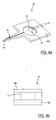
- the reaction area 12 has a thickness equal to the thickness of the fluid collection apparatus 10 and/or the sheet of material.
- the three piece construction is advantageous for an optical transmission design because the light source is on one side and the photodetector is on the other side of the reaction area 12.
- FIGS. 5-6b the process for manufacturing the integrated fluid collection apparatus 10 will be described.
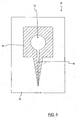
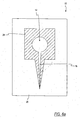
- a first side 20 of a sheet of material 22 is coated (or masked) in a particular pattern 24 with a photoresist.
- the pattern 24 is in the shape of the fluid collection apparatus 10.
- a coating shown by the diagonal lines is formed around the reaction area 12, thus defining the reaction area 12.
- the coating also does not cover, the capillary channel 16 but, instead, defines the channel 16.
- FIG. 6a is the manufacturing of the three piece apparatus, or the apparatus shown in FIG. 4a .
- the coating on the second side 26 is in the pattern 24 of the first side 20.
- the reaction area 12 and the capillary channel 16 remain unmasked.
- the capillary channel could also be masked on the second side, but is not shown.
- the photoresist is spread in a pattern 28 that extends over the whole shape of the fluid collection apparatus 10.
- the reaction area 12 and the capillary channel 16 are coated. This pattern creates the two piece apparatus shown in FIG. 3a .
- the sheet 22 is then exposed using lithography.
- the photoresist is hardened by exposing it to ultraviolet light.
- the sheet 22 is then placed in a solvent, such as an acid.
- the solvent mills or etches the uncoated portions of the material.
- the hardened photoresist protects the coated portion of the material from the acid.
- a predetermined amount of time i.e., time sufficient for the solvent to eat through the sheet
- the fluid collection apparatus 10 can be Manufactured in only a few steps. Since the lance 14 and the reaction area 12 are one piece, they may be manufactured using this common chemical milling process. By making the lance 14, the capillary channel 16, and the reaction area 12 all one piece, the manufacturing time is reduced, as is the need for extra parts or machines to manufacture the different pieces.
- reaction area 12 and the capillary channel 16 are being milled from both sides.
- the reaction area 12 and the, capillary channel 16 are formed by the acid milling through the entire thickeness of the material. This results in the fluid collection apparatus shown in FIG. 4a .
- the reaction area 12 and the capillary channel 16 are only left exposed on one side.
- the reaction area 12 and the capillary channel 16 will only be milled on one side.
- the fluid collection apparatus 10 will have a reaction area 12 and a capillary channel 16 that has half the thickness of the sheet 22. This method results in the fluid collection apparatus shown in FIG. 3a .
- the first side 20 of the sheet 22 may be milled using a first acid, while the second side 26 is milled using a second, different acid, having a different strength.
- the acids can be used to create different thicknesses for the reaction area 12 and the capillary channel 16.
- the stronger acid will have eroded more than half of the sheet 22, thus the thickness of the reaction area 12 and the capillary channel 16 will be greater than half the thickness of the sheet 22.
- the weaker acid is used on the first side 20, the thicknesses of the reaction area 12 and the capillary channel 16 will be less than half the thickness of the sheet 22.
- the fluid collection apparatus 10 typically has a width ranging from about 0.060 to about' 0.090 inches and a length ranging from about 0.120 to about 0.180 inches.
- the reaction area 12 is shown as generally circular and has a radius ranging from about 0.010 to about 0.030 inches, however, the shape can be oval, diamond, or of a shape to optimize the fluid flow into the reaction chamber.
- the capillary channel 16 has a width ranging from about 0.001 to about 0.005 inches.
- the fluid collection apparatus 10 is preferably made of metal, such as stainless steel.
- the lid 10b is attached to one side of the fluid collection apparatus.
- the lid 10b may include the electrochemical electrodes 17 if electrochemical testing is taking place.
- the lid 10b may be a clear plastic window if optical testing is taking place.
- the second cover 10c is also attached to a side of the fluid• collection apparatus 10.
- the fluid collection apparatus 10 will be described.
- a user will pierce their skin (e.g., a finger tip) using the lance 14 located on the end of the fluid collection apparatus 10.
- the blood is drawn up into the capillary channel 16 ,through capillary action, and into the reaction area 12, where it mixes with the reagent 13, creating a measurable reaction as described .above.
- the fluid collection apparatus 10 is used with a test device (not shown) to measure the reaction.
- the testing device may be a colorimetric spectrophotometer or current measuring for the electrochemical sensor as described above.
- FIG. 7 a sheet of material 28 with a plurality of fluid collection apparatuses 10 is depicted.
- FIG. 8 is an enlarged view of a portion of the sheet 28.
- a plurality of fluid collection apparatuses 10 may be to formed on each sheet 28 as shown in FIG. 7 .
- the number of fluid collection apparatuses 10 on each sheet 28 may be modified to suit individual needs.
- By manufacturing numerous apparatuses 10 on one sheet many apparatuses 10 can be dipped in the acid at the same time; which enables quick manufacturing of the fluid collection apparatus 10. It is advantageous to be able to mass produce the apparatuses is since that decreases the time and cost of production. Also, there is less sheet of material that is wasted or that needs to be milled by the etchant, which also decreases the manufacturing cost since there is less excess material.
- the fluid collection apparatuses 10 are formed on a continuous web of material.
- the webs may be manufactured in rolls and continuously fed through the manufacturing machine. Utilizing a continuous web of material also allows for continuous manufacturing of the fluid collection apparatuses 10, which is advantageous since it decreases production costs.
- the fluid collection apparatuses 10 may be manufactured by micromachining or, put another way, cutting the fluid collection apparatuses with machinery instead of using acid.
- the outer edges of the fluid collection apparatuses may be cut using standard machining or lasers.
- the capillary channel 16 and the reaction area 14 may be manufactured by diamond cutting.
- the reaction area 14 may also be made by lasers, if the reaction area 14 has a thickness equal to the thickness of the sheet.
- the points of the lance 14 may also be cut by diamond tools or lasers.
Landscapes
- Health & Medical Sciences (AREA)
- Life Sciences & Earth Sciences (AREA)
- Engineering & Computer Science (AREA)
- Physics & Mathematics (AREA)
- Molecular Biology (AREA)
- General Health & Medical Sciences (AREA)
- Biophysics (AREA)
- Biomedical Technology (AREA)
- Heart & Thoracic Surgery (AREA)
- Medical Informatics (AREA)
- Veterinary Medicine (AREA)
- Surgery (AREA)
- Animal Behavior & Ethology (AREA)
- Pathology (AREA)
- Public Health (AREA)
- Hematology (AREA)
- Manufacturing & Machinery (AREA)
- Dermatology (AREA)
- Emergency Medicine (AREA)
- Optics & Photonics (AREA)
- Measurement Of The Respiration, Hearing Ability, Form, And Blood Characteristics Of Living Organisms (AREA)
- Investigating Or Analysing Biological Materials (AREA)
- Devices For Use In Laboratory Experiments (AREA)
Claims (11)
- Vorrichtung (10) zum Sammeln von Flüssigkeiten, umfassend:eine Lanzette (14) mit einer Nase zum Einstechen in die Haut zur Entnahme einer Probe;einen Reaktionsbereich (12), der ein Reagenz (13) zur Reaktion mit einem Analyten in der Probe enthält, wobei die Reaktion eine Messung einer Konzentration des Analyten in der Probe bereitstellt; undeinen Kapillarkanal (16), der die Lanzette (14) mit dem Reaktionsbereich (12) verbindet, wobei der Kapillarkanal (16) die Probe von der Nase der Lanzette (14) zu dem Reaktionsbereich (12) zieht,wobei die Lanzette (14), der Reaktionsbereich (12) und der Kapillarkanal (16) aus einem einzelnen Material einstückig geformt sind, dadurch gekennzeichnet, dass die Nase zwei geschärfte Spitzen auf gegenüberliegenden Seiten des Kapillarkanals (16) aufweist.
- Vorrichtung (10) zum Sammeln von Flüssigkeiten nach Anspruch 1, worin die Vorrichtung (10) zum Sammeln von Flüssigkeiten einen Körper (10a) und einen Deckel (10b) aufweist, wobei die Lanzette (14), der Reaktionsbereich (12) und der Kapillarkanal (16) von dem Körper (10a) geformt werden und der Deckel (10b) den Reaktionsbereich (12) abdeckt.
- Vorrichtung (10) zum Sammeln von Flüssigkeiten nach Anspruch 1 oder 2, worin der Reaktionsbereich (12) die Dicke des Kapillarkanals (16) aufweist.
- Vorrichtung (10) zum Sammeln von Flüssigkeiten nach einem der Ansprüche 1 bis 3, worin die Dicke des Kapillarkanals (16) ungefähr die Hälfte des Körpers (10a) beträgt.
- Vorrichtung (10) zum Sammeln von Flüssigkeiten nach Anspruch 1, worin die Vorrichtung (10) zum Sammeln von Flüssigkeiten einen Körper (10a), einen Deckel (10b) und eine Abdeckung (10c) aufweist, wobei die Lanzette (14), der Reaktionsbereich (12) und der Kapillarkanal (16) von dem Körper (10a) geformt werden.
- Vorrichtung (10) zum Sammeln von Flüssigkeiten nach Anspruch 5, worin der Reaktionsbereich (12) die Dicke des Kapillarkanals (16) aufweist.
- Vorrichtung zum Sammeln von Flüssigkeiten nach einem der Ansprüche 1 bis 6,worin die Lanzette (14), der Reaktionsbereich (12) und der Kapillarkanal (16) aus einem Metallblech geformt sind.
- Vorrichtung (10) zum Sammeln von Flüssigkeiten nach einem der Ansprüche 2, 5 oder 6, worin der Deckel (10b) transparent ist.
- Vorrichtung (10) zum Sammeln von Flüssigkeiten nach einem der Ansprüche 2, 5 oder 6, worin der Deckel (10b) elektrochemische Elektroden aufweist.
- Vorrichtung (10) zum Sammeln von Flüssigkeiten nach einem der Ansprüche 1 bis 9, worin der Kapillarkanal (16) in den Körper (10a) gefräst ist.
- Vorrichtung (10) zum Sammeln von Flüssigkeiten nach einem der Ansprüche 1 bis 10, worin der Reaktionsbereich (12) in die erste Seite des Körpers (10a) gefräst ist.
Applications Claiming Priority (2)
| Application Number | Priority Date | Filing Date | Title |
|---|---|---|---|
| US36140502P | 2002-03-05 | 2002-03-05 | |
| EP03003256A EP1346686B1 (de) | 2002-03-05 | 2003-02-24 | Vorrichtung zum Sammeln von Flüssigkeiten mit integrierter Lanzette und Reaktionsbereich |
Related Parent Applications (2)
| Application Number | Title | Priority Date | Filing Date |
|---|---|---|---|
| EP03003256A Division EP1346686B1 (de) | 2002-03-05 | 2003-02-24 | Vorrichtung zum Sammeln von Flüssigkeiten mit integrierter Lanzette und Reaktionsbereich |
| EP03003256.9 Division | 2003-02-24 |
Publications (3)
| Publication Number | Publication Date |
|---|---|
| EP2277442A2 EP2277442A2 (de) | 2011-01-26 |
| EP2277442A3 EP2277442A3 (de) | 2011-07-06 |
| EP2277442B1 true EP2277442B1 (de) | 2015-06-24 |
Family
ID=27789115
Family Applications (2)
| Application Number | Title | Priority Date | Filing Date |
|---|---|---|---|
| EP03003256A Expired - Lifetime EP1346686B1 (de) | 2002-03-05 | 2003-02-24 | Vorrichtung zum Sammeln von Flüssigkeiten mit integrierter Lanzette und Reaktionsbereich |
| EP10183624.5A Expired - Lifetime EP2277442B1 (de) | 2002-03-05 | 2003-02-24 | Vorrichtung zum Sammeln von Flüssigkeiten mit integrierter Lanzette und Reaktionsbereich |
Family Applications Before (1)
| Application Number | Title | Priority Date | Filing Date |
|---|---|---|---|
| EP03003256A Expired - Lifetime EP1346686B1 (de) | 2002-03-05 | 2003-02-24 | Vorrichtung zum Sammeln von Flüssigkeiten mit integrierter Lanzette und Reaktionsbereich |
Country Status (6)
| Country | Link |
|---|---|
| US (1) | US20030171699A1 (de) |
| EP (2) | EP1346686B1 (de) |
| JP (1) | JP4460840B2 (de) |
| AT (1) | ATE555724T1 (de) |
| AU (1) | AU2003200797A1 (de) |
| CA (1) | CA2419200C (de) |
Families Citing this family (59)
| Publication number | Priority date | Publication date | Assignee | Title |
|---|---|---|---|---|
| US7310543B2 (en) * | 2001-03-26 | 2007-12-18 | Kumetrix, Inc. | Silicon microprobe with integrated biosensor |
| DE10134650B4 (de) | 2001-07-20 | 2009-12-03 | Roche Diagnostics Gmbh | System zur Entnahme kleiner Körperflüssigkeitsmengen |
| US7060192B2 (en) * | 2002-05-09 | 2006-06-13 | Lifescan, Inc. | Methods of fabricating physiological sample collection devices |
| US20030212344A1 (en) * | 2002-05-09 | 2003-11-13 | Vadim Yuzhakov | Physiological sample collection devices and methods of using the same |
| US20040138688A1 (en) * | 2002-10-09 | 2004-07-15 | Jean Pierre Giraud | Lancet system including test strips and cassettes for drawing and sampling bodily material |
| US7815579B2 (en) * | 2005-03-02 | 2010-10-19 | Roche Diagnostics Operations, Inc. | Dynamic integrated lancing test strip with sterility cover |
| US20040193202A1 (en) * | 2003-03-28 | 2004-09-30 | Allen John J. | Integrated lance and strip for analyte measurement |
| US20040193072A1 (en) * | 2003-03-28 | 2004-09-30 | Allen John J. | Method of analyte measurement using integrated lance and strip |
| US7473264B2 (en) * | 2003-03-28 | 2009-01-06 | Lifescan, Inc. | Integrated lance and strip for analyte measurement |
| US20040248312A1 (en) * | 2003-06-06 | 2004-12-09 | Bayer Healthcare, Llc | Sensor with integrated lancet |
| US7361182B2 (en) | 2003-12-19 | 2008-04-22 | Lightnix, Inc. | Medical lancet |
| KR20060130657A (ko) * | 2004-03-18 | 2006-12-19 | 후지 샤신 필름 가부시기가이샤 | 검체 검사방법에 사용되는 분석요소 |
| US7909776B2 (en) * | 2004-04-30 | 2011-03-22 | Roche Diagnostics Operations, Inc. | Lancets for bodily fluid sampling supplied on a tape |
| US8591436B2 (en) | 2004-04-30 | 2013-11-26 | Roche Diagnostics Operations, Inc. | Lancets for bodily fluid sampling supplied on a tape |
| US7322942B2 (en) * | 2004-05-07 | 2008-01-29 | Roche Diagnostics Operations, Inc. | Integrated disposable for automatic or manual blood dosing |
| EP1627684A1 (de) * | 2004-08-20 | 2006-02-22 | F. Hoffmann-La Roche Ag | Mikrofluidiksystem und Verfahren zu dessen Herstellung |
| WO2006029320A1 (en) * | 2004-09-09 | 2006-03-16 | Bayer Healthcare Llc | Damping system for a lancet using compressed air |
| EP1654985A1 (de) * | 2004-11-09 | 2006-05-10 | F. Hoffmann-La Roche Ag | Probenentnahmesystem für Probenflüssigkeit |
| EP1671585A1 (de) * | 2004-12-17 | 2006-06-21 | F. Hoffmann-La Roche Ag | Verfahren zur Herstellung eines Stechelements |
| US7935063B2 (en) * | 2005-03-02 | 2011-05-03 | Roche Diagnostics Operations, Inc. | System and method for breaking a sterility seal to engage a lancet |
| WO2006096539A1 (en) | 2005-03-04 | 2006-09-14 | Bayer Healthcare Llc | Lancet-release mechanism |
| EP1865848A1 (de) | 2005-03-04 | 2007-12-19 | Bayer HealthCare LLC | Lanzettenauslösungsmechanismus |
| KR101381331B1 (ko) | 2005-05-09 | 2014-04-04 | 테라노스, 인코포레이티드 | 현장진료 유체 시스템 및 그 용도 |
| WO2007005493A2 (en) * | 2005-06-30 | 2007-01-11 | Bayer Healthcare Llc | Single-puncture lancing system |
| WO2007011645A1 (en) * | 2005-07-14 | 2007-01-25 | Bayer Healthcare Llc | Lancing device for one skin puncture |
| US8636672B2 (en) * | 2007-02-28 | 2014-01-28 | Nipro Diagnostics, Inc. | Test strip with integrated lancet |
| AR057484A1 (es) | 2005-08-04 | 2007-12-05 | Bayer Healthcare Llc | Dispositvo de puncion pequeno |
| US20070031293A1 (en) * | 2005-08-04 | 2007-02-08 | Beatty Christopher C | Method and apparatus for collecting and diluting a liquid sample |
| EP1752755B1 (de) | 2005-08-10 | 2015-05-06 | Roche Diagnostics GmbH | Probenaufnahme- und-dosiervorrichtung mit integrierten Flüssigkeitskompartimenten |
| EP1759633A1 (de) * | 2005-09-01 | 2007-03-07 | F.Hoffmann-La Roche Ag | Anordnung zum Aufnehmen von Körperflüssigkeiten sowie Herstellungsverfahren hierfür |
| JP4935286B2 (ja) * | 2005-10-12 | 2012-05-23 | パナソニック株式会社 | 血液センサ |
| EP1790288A1 (de) * | 2005-11-25 | 2007-05-30 | Roche Diagnostics GmbH | Geknickte Lanzette |
| JPWO2007063948A1 (ja) * | 2005-12-01 | 2009-05-07 | アークレイ株式会社 | センサ−ランセット一体型デバイス、およびこれを用いた体液採取方法 |
| US11287421B2 (en) | 2006-03-24 | 2022-03-29 | Labrador Diagnostics Llc | Systems and methods of sample processing and fluid control in a fluidic system |
| US8007999B2 (en) | 2006-05-10 | 2011-08-30 | Theranos, Inc. | Real-time detection of influenza virus |
| EP1878387B1 (de) | 2006-07-15 | 2010-11-24 | Roche Diagnostics GmbH | Lanzette, Lanzettenvorratsband und Stechgerät zum Erzeugen einer Einstichwunde |
| EP1878386A1 (de) | 2006-07-15 | 2008-01-16 | Roche Diagnostics GmbH | Verfahren zum Herstellen einer Lanzette, Lanzette, Lanzettenvorratsband und Stechgerät zum Erzeugen einer Einstichwunde mittels einer solchen Lanzette |
| EP1891898A1 (de) * | 2006-08-25 | 2008-02-27 | Roche Diagnostics GmbH | Stechgerät |
| JP2010502267A (ja) * | 2006-08-28 | 2010-01-28 | エージェンシー・フォー・サイエンス・テクノロジー・アンド・リサーチ | マイクロニードルおよびマイクロニードルの製造方法 |
| WO2008036043A1 (en) * | 2006-09-18 | 2008-03-27 | Agency For Science, Technology And Research | Needle structures and methods for fabricating needle structures |
| US8012744B2 (en) | 2006-10-13 | 2011-09-06 | Theranos, Inc. | Reducing optical interference in a fluidic device |
| ATE430514T1 (de) * | 2006-10-14 | 2009-05-15 | Hoffmann La Roche | Lanzette mit kapillarkanal |
| US20080113391A1 (en) | 2006-11-14 | 2008-05-15 | Ian Gibbons | Detection and quantification of analytes in bodily fluids |
| WO2008111936A1 (en) * | 2007-03-12 | 2008-09-18 | Bayer Healthcare Llc | Lancet-eject mechanism |
| KR100874221B1 (ko) * | 2007-03-20 | 2008-12-15 | 주식회사 지니메디 | 체액 성분 측정 장치 |
| EP1982653A1 (de) * | 2007-04-18 | 2008-10-22 | Roche Diagnostics GmbH | Stechgerät und Analysegerät |
| JPWO2009008193A1 (ja) * | 2007-07-11 | 2010-09-02 | 日東電工株式会社 | 体液採取用回路基板 |
| US8158430B1 (en) | 2007-08-06 | 2012-04-17 | Theranos, Inc. | Systems and methods of fluidic sample processing |
| US8088593B2 (en) | 2007-10-02 | 2012-01-03 | Theranos, Inc. | Modular point-of-care devices, systems, and uses thereof |
| US7766846B2 (en) | 2008-01-28 | 2010-08-03 | Roche Diagnostics Operations, Inc. | Rapid blood expression and sampling |
| US20100292610A1 (en) * | 2008-02-06 | 2010-11-18 | Jun Ishii | Circuit board for body fluid collection |
| JP2009225934A (ja) | 2008-03-21 | 2009-10-08 | Nitto Denko Corp | 体液採取用回路基板およびバイオセンサ |
| JP2009225936A (ja) | 2008-03-21 | 2009-10-08 | Nitto Denko Corp | 体液採取用回路基板、その製造方法、その使用方法およびバイオセンサ |
| EP2316339A4 (de) * | 2008-08-01 | 2012-10-24 | Lightnix Inc | Sensor mit feiner nadel mit darin gebildetem kanal |
| EP2248463A1 (de) | 2009-05-09 | 2010-11-10 | F. Hoffmann-La Roche AG | Testeinheit zum Einsatz in einem Testgerät und Testsystem |
| EP2272429A1 (de) * | 2009-07-10 | 2011-01-12 | Roche Diagnostics GmbH | Lanzette |
| CN105808956A (zh) | 2009-10-19 | 2016-07-27 | 提拉诺斯公司 | 集成的健康数据采集和分析系统 |
| CN106323875B (zh) | 2011-01-21 | 2019-07-09 | 西拉诺斯知识产权有限责任公司 | 样品使用最大化的系统和方法 |
| US20130274768A1 (en) | 2012-02-29 | 2013-10-17 | Marker Medical, Llc | Surgical apparatus and method |
Family Cites Families (13)
| Publication number | Priority date | Publication date | Assignee | Title |
|---|---|---|---|---|
| US4587202A (en) | 1984-12-14 | 1986-05-06 | Ethicon, Inc. | Photoetching process for making surgical needles |
| CA2100238A1 (en) * | 1992-08-03 | 1994-02-04 | Michael Haroldsen | Needles made from non-round stock |
| US5582184A (en) * | 1993-10-13 | 1996-12-10 | Integ Incorporated | Interstitial fluid collection and constituent measurement |
| WO1995022051A1 (en) * | 1994-02-09 | 1995-08-17 | Abbott Laboratories | Diagnostic flow cell device |
| US5591139A (en) * | 1994-06-06 | 1997-01-07 | The Regents Of The University Of California | IC-processed microneedles |
| US5611999A (en) * | 1995-09-05 | 1997-03-18 | Bayer Corporation | Diffused light reflectance readhead |
| US5801057A (en) * | 1996-03-22 | 1998-09-01 | Smart; Wilson H. | Microsampling device and method of construction |
| US5723284A (en) * | 1996-04-01 | 1998-03-03 | Bayer Corporation | Control solution and method for testing the performance of an electrochemical device for determining the concentration of an analyte in blood |
| AU2189400A (en) * | 1998-12-18 | 2000-07-03 | Minimed, Inc. | Insertion sets with micro-piercing members for use with medical devices and methods of using the same |
| US6102927A (en) * | 1999-04-30 | 2000-08-15 | Wright; George A. | Blood lancet and method of manufacture |
| US6612111B1 (en) * | 2000-03-27 | 2003-09-02 | Lifescan, Inc. | Method and device for sampling and analyzing interstitial fluid and whole blood samples |
| GB0030929D0 (en) * | 2000-12-19 | 2001-01-31 | Inverness Medical Ltd | Analyte measurement |
| US20030143113A2 (en) * | 2002-05-09 | 2003-07-31 | Lifescan, Inc. | Physiological sample collection devices and methods of using the same |
-
2003
- 2003-02-19 CA CA2419200A patent/CA2419200C/en not_active Expired - Fee Related
- 2003-02-20 US US10/368,859 patent/US20030171699A1/en not_active Abandoned
- 2003-02-24 AT AT03003256T patent/ATE555724T1/de active
- 2003-02-24 EP EP03003256A patent/EP1346686B1/de not_active Expired - Lifetime
- 2003-02-24 EP EP10183624.5A patent/EP2277442B1/de not_active Expired - Lifetime
- 2003-03-03 AU AU2003200797A patent/AU2003200797A1/en not_active Withdrawn
- 2003-03-04 JP JP2003057622A patent/JP4460840B2/ja not_active Expired - Fee Related
Also Published As
| Publication number | Publication date |
|---|---|
| JP2004000493A (ja) | 2004-01-08 |
| EP1346686A2 (de) | 2003-09-24 |
| EP1346686A3 (de) | 2004-06-16 |
| ATE555724T1 (de) | 2012-05-15 |
| CA2419200A1 (en) | 2003-09-05 |
| CA2419200C (en) | 2015-06-30 |
| JP4460840B2 (ja) | 2010-05-12 |
| US20030171699A1 (en) | 2003-09-11 |
| EP2277442A2 (de) | 2011-01-26 |
| EP2277442A3 (de) | 2011-07-06 |
| EP1346686B1 (de) | 2012-05-02 |
| AU2003200797A1 (en) | 2003-09-25 |
Similar Documents
| Publication | Publication Date | Title |
|---|---|---|
| EP1346686B1 (de) | Vorrichtung zum Sammeln von Flüssigkeiten mit integrierter Lanzette und Reaktionsbereich | |
| CA2350307C (en) | Hollow microneedle patch | |
| EP1839577B1 (de) | Sensor mit integrierter Lanzette | |
| CA2350313C (en) | Thin lance and test sensor having same | |
| US20040248312A1 (en) | Sensor with integrated lancet | |
| EP1360933B1 (de) | Verfahren und Vorrichtung zur Sammlung von physiologischen Proben | |
| CA2396251A1 (en) | Physiological sample collection devices and methods of using the same | |
| EP1275963B1 (de) | Volumenzähler-Prüfvorrichtung | |
| WO2006065702A1 (en) | Marker for readings taken from alternative site tests | |
| WO2007047812A2 (en) | Analyte-testing instruments having antimicrobial properties and methods of using the same | |
| HK1057984B (en) | Physiological sample collection devices and methods of using the same |
Legal Events
| Date | Code | Title | Description |
|---|---|---|---|
| PUAI | Public reference made under article 153(3) epc to a published international application that has entered the european phase |
Free format text: ORIGINAL CODE: 0009012 |
|
| AC | Divisional application: reference to earlier application |
Ref document number: 1346686 Country of ref document: EP Kind code of ref document: P |
|
| AK | Designated contracting states |
Kind code of ref document: A2 Designated state(s): AT BE BG CH CY CZ DE DK EE ES FI FR GB GR HU IE IT LI LU MC NL PT SE SI SK TR |
|
| PUAL | Search report despatched |
Free format text: ORIGINAL CODE: 0009013 |
|
| AK | Designated contracting states |
Kind code of ref document: A3 Designated state(s): AT BE BG CH CY CZ DE DK EE ES FI FR GB GR HU IE IT LI LU MC NL PT SE SI SK TR |
|
| 17P | Request for examination filed |
Effective date: 20120109 |
|
| 17Q | First examination report despatched |
Effective date: 20130705 |
|
| RAP1 | Party data changed (applicant data changed or rights of an application transferred) |
Owner name: BAYER HEALTHCARE LLC |
|
| GRAP | Despatch of communication of intention to grant a patent |
Free format text: ORIGINAL CODE: EPIDOSNIGR1 |
|
| INTG | Intention to grant announced |
Effective date: 20150212 |
|
| GRAS | Grant fee paid |
Free format text: ORIGINAL CODE: EPIDOSNIGR3 |
|
| GRAA | (expected) grant |
Free format text: ORIGINAL CODE: 0009210 |
|
| AC | Divisional application: reference to earlier application |
Ref document number: 1346686 Country of ref document: EP Kind code of ref document: P |
|
| AK | Designated contracting states |
Kind code of ref document: B1 Designated state(s): AT BE BG CH CY CZ DE DK EE ES FI FR GB GR HU IE IT LI LU MC NL PT SE SI SK TR |
|
| REG | Reference to a national code |
Ref country code: GB Ref legal event code: FG4D |
|
| REG | Reference to a national code |
Ref country code: CH Ref legal event code: EP |
|
| REG | Reference to a national code |
Ref country code: AT Ref legal event code: REF Ref document number: 732556 Country of ref document: AT Kind code of ref document: T Effective date: 20150715 |
|
| REG | Reference to a national code |
Ref country code: IE Ref legal event code: FG4D |
|
| REG | Reference to a national code |
Ref country code: DE Ref legal event code: R096 Ref document number: 60347751 Country of ref document: DE |
|
| PG25 | Lapsed in a contracting state [announced via postgrant information from national office to epo] |
Ref country code: FI Free format text: LAPSE BECAUSE OF FAILURE TO SUBMIT A TRANSLATION OF THE DESCRIPTION OR TO PAY THE FEE WITHIN THE PRESCRIBED TIME-LIMIT Effective date: 20150624 |
|
| REG | Reference to a national code |
Ref country code: AT Ref legal event code: MK05 Ref document number: 732556 Country of ref document: AT Kind code of ref document: T Effective date: 20150624 |
|
| PG25 | Lapsed in a contracting state [announced via postgrant information from national office to epo] |
Ref country code: GR Free format text: LAPSE BECAUSE OF FAILURE TO SUBMIT A TRANSLATION OF THE DESCRIPTION OR TO PAY THE FEE WITHIN THE PRESCRIBED TIME-LIMIT Effective date: 20150925 Ref country code: BG Free format text: LAPSE BECAUSE OF FAILURE TO SUBMIT A TRANSLATION OF THE DESCRIPTION OR TO PAY THE FEE WITHIN THE PRESCRIBED TIME-LIMIT Effective date: 20150924 |
|
| REG | Reference to a national code |
Ref country code: NL Ref legal event code: MP Effective date: 20150624 |
|
| PG25 | Lapsed in a contracting state [announced via postgrant information from national office to epo] |
Ref country code: EE Free format text: LAPSE BECAUSE OF FAILURE TO SUBMIT A TRANSLATION OF THE DESCRIPTION OR TO PAY THE FEE WITHIN THE PRESCRIBED TIME-LIMIT Effective date: 20150624 |
|
| REG | Reference to a national code |
Ref country code: FR Ref legal event code: PLFP Year of fee payment: 14 |
|
| PG25 | Lapsed in a contracting state [announced via postgrant information from national office to epo] |
Ref country code: CZ Free format text: LAPSE BECAUSE OF FAILURE TO SUBMIT A TRANSLATION OF THE DESCRIPTION OR TO PAY THE FEE WITHIN THE PRESCRIBED TIME-LIMIT Effective date: 20150624 Ref country code: ES Free format text: LAPSE BECAUSE OF FAILURE TO SUBMIT A TRANSLATION OF THE DESCRIPTION OR TO PAY THE FEE WITHIN THE PRESCRIBED TIME-LIMIT Effective date: 20150624 Ref country code: SK Free format text: LAPSE BECAUSE OF FAILURE TO SUBMIT A TRANSLATION OF THE DESCRIPTION OR TO PAY THE FEE WITHIN THE PRESCRIBED TIME-LIMIT Effective date: 20150624 Ref country code: AT Free format text: LAPSE BECAUSE OF FAILURE TO SUBMIT A TRANSLATION OF THE DESCRIPTION OR TO PAY THE FEE WITHIN THE PRESCRIBED TIME-LIMIT Effective date: 20150624 Ref country code: PT Free format text: LAPSE BECAUSE OF FAILURE TO SUBMIT A TRANSLATION OF THE DESCRIPTION OR TO PAY THE FEE WITHIN THE PRESCRIBED TIME-LIMIT Effective date: 20151026 |
|
| REG | Reference to a national code |
Ref country code: DE Ref legal event code: R097 Ref document number: 60347751 Country of ref document: DE |
|
| PG25 | Lapsed in a contracting state [announced via postgrant information from national office to epo] |
Ref country code: DK Free format text: LAPSE BECAUSE OF FAILURE TO SUBMIT A TRANSLATION OF THE DESCRIPTION OR TO PAY THE FEE WITHIN THE PRESCRIBED TIME-LIMIT Effective date: 20150624 Ref country code: IT Free format text: LAPSE BECAUSE OF FAILURE TO SUBMIT A TRANSLATION OF THE DESCRIPTION OR TO PAY THE FEE WITHIN THE PRESCRIBED TIME-LIMIT Effective date: 20150624 |
|
| PGFP | Annual fee paid to national office [announced via postgrant information from national office to epo] |
Ref country code: DE Payment date: 20160226 Year of fee payment: 14 |
|
| PLBE | No opposition filed within time limit |
Free format text: ORIGINAL CODE: 0009261 |
|
| STAA | Information on the status of an ep patent application or granted ep patent |
Free format text: STATUS: NO OPPOSITION FILED WITHIN TIME LIMIT |
|
| PG25 | Lapsed in a contracting state [announced via postgrant information from national office to epo] |
Ref country code: BE Free format text: LAPSE BECAUSE OF NON-PAYMENT OF DUE FEES Effective date: 20160229 |
|
| PGFP | Annual fee paid to national office [announced via postgrant information from national office to epo] |
Ref country code: FR Payment date: 20160217 Year of fee payment: 14 Ref country code: GB Payment date: 20160226 Year of fee payment: 14 |
|
| 26N | No opposition filed |
Effective date: 20160329 |
|
| PG25 | Lapsed in a contracting state [announced via postgrant information from national office to epo] |
Ref country code: SI Free format text: LAPSE BECAUSE OF FAILURE TO SUBMIT A TRANSLATION OF THE DESCRIPTION OR TO PAY THE FEE WITHIN THE PRESCRIBED TIME-LIMIT Effective date: 20150624 |
|
| PG25 | Lapsed in a contracting state [announced via postgrant information from national office to epo] |
Ref country code: LU Free format text: LAPSE BECAUSE OF FAILURE TO SUBMIT A TRANSLATION OF THE DESCRIPTION OR TO PAY THE FEE WITHIN THE PRESCRIBED TIME-LIMIT Effective date: 20160224 Ref country code: MC Free format text: LAPSE BECAUSE OF FAILURE TO SUBMIT A TRANSLATION OF THE DESCRIPTION OR TO PAY THE FEE WITHIN THE PRESCRIBED TIME-LIMIT Effective date: 20150624 |
|
| REG | Reference to a national code |
Ref country code: CH Ref legal event code: PL |
|
| PG25 | Lapsed in a contracting state [announced via postgrant information from national office to epo] |
Ref country code: LI Free format text: LAPSE BECAUSE OF NON-PAYMENT OF DUE FEES Effective date: 20160229 Ref country code: CH Free format text: LAPSE BECAUSE OF NON-PAYMENT OF DUE FEES Effective date: 20160229 |
|
| REG | Reference to a national code |
Ref country code: IE Ref legal event code: MM4A |
|
| PG25 | Lapsed in a contracting state [announced via postgrant information from national office to epo] |
Ref country code: BE Free format text: LAPSE BECAUSE OF FAILURE TO SUBMIT A TRANSLATION OF THE DESCRIPTION OR TO PAY THE FEE WITHIN THE PRESCRIBED TIME-LIMIT Effective date: 20150624 |
|
| PG25 | Lapsed in a contracting state [announced via postgrant information from national office to epo] |
Ref country code: IE Free format text: LAPSE BECAUSE OF NON-PAYMENT OF DUE FEES Effective date: 20160224 |
|
| PG25 | Lapsed in a contracting state [announced via postgrant information from national office to epo] |
Ref country code: NL Free format text: LAPSE BECAUSE OF FAILURE TO SUBMIT A TRANSLATION OF THE DESCRIPTION OR TO PAY THE FEE WITHIN THE PRESCRIBED TIME-LIMIT Effective date: 20150624 Ref country code: SE Free format text: LAPSE BECAUSE OF FAILURE TO SUBMIT A TRANSLATION OF THE DESCRIPTION OR TO PAY THE FEE WITHIN THE PRESCRIBED TIME-LIMIT Effective date: 20150624 |
|
| REG | Reference to a national code |
Ref country code: DE Ref legal event code: R119 Ref document number: 60347751 Country of ref document: DE |
|
| GBPC | Gb: european patent ceased through non-payment of renewal fee |
Effective date: 20170224 |
|
| REG | Reference to a national code |
Ref country code: FR Ref legal event code: ST Effective date: 20171031 |
|
| PG25 | Lapsed in a contracting state [announced via postgrant information from national office to epo] |
Ref country code: FR Free format text: LAPSE BECAUSE OF NON-PAYMENT OF DUE FEES Effective date: 20170228 Ref country code: DE Free format text: LAPSE BECAUSE OF NON-PAYMENT OF DUE FEES Effective date: 20170901 |
|
| PG25 | Lapsed in a contracting state [announced via postgrant information from national office to epo] |
Ref country code: GB Free format text: LAPSE BECAUSE OF NON-PAYMENT OF DUE FEES Effective date: 20170224 |
|
| PG25 | Lapsed in a contracting state [announced via postgrant information from national office to epo] |
Ref country code: HU Free format text: LAPSE BECAUSE OF FAILURE TO SUBMIT A TRANSLATION OF THE DESCRIPTION OR TO PAY THE FEE WITHIN THE PRESCRIBED TIME-LIMIT; INVALID AB INITIO Effective date: 20030224 Ref country code: CY Free format text: LAPSE BECAUSE OF FAILURE TO SUBMIT A TRANSLATION OF THE DESCRIPTION OR TO PAY THE FEE WITHIN THE PRESCRIBED TIME-LIMIT Effective date: 20150624 |
|
| PG25 | Lapsed in a contracting state [announced via postgrant information from national office to epo] |
Ref country code: TR Free format text: LAPSE BECAUSE OF FAILURE TO SUBMIT A TRANSLATION OF THE DESCRIPTION OR TO PAY THE FEE WITHIN THE PRESCRIBED TIME-LIMIT Effective date: 20150624 |