EP2277375B1 - Fishing spinning reel - Google Patents
Fishing spinning reel Download PDFInfo
- Publication number
- EP2277375B1 EP2277375B1 EP10167675.7A EP10167675A EP2277375B1 EP 2277375 B1 EP2277375 B1 EP 2277375B1 EP 10167675 A EP10167675 A EP 10167675A EP 2277375 B1 EP2277375 B1 EP 2277375B1
- Authority
- EP
- European Patent Office
- Prior art keywords
- main body
- rotor
- portions
- arm portions
- spinning reel
- Prior art date
- Legal status (The legal status is an assumption and is not a legal conclusion. Google has not performed a legal analysis and makes no representation as to the accuracy of the status listed.)
- Active
Links
Images


Classifications
-
- A—HUMAN NECESSITIES
- A01—AGRICULTURE; FORESTRY; ANIMAL HUSBANDRY; HUNTING; TRAPPING; FISHING
- A01K—ANIMAL HUSBANDRY; AVICULTURE; APICULTURE; PISCICULTURE; FISHING; REARING OR BREEDING ANIMALS, NOT OTHERWISE PROVIDED FOR; NEW BREEDS OF ANIMALS
- A01K89/00—Reels
- A01K89/01—Reels with pick-up, i.e. with the guiding member rotating and the spool not rotating during normal retrieval of the line
- A01K89/0108—Pick-up details
- A01K89/01081—Guiding members on rotor axially rearward of spool
- A01K89/01082—Guiding members shiftable on rotor
- A01K89/01083—Guiding members shiftable on rotor to wind position by rotor drive
-
- A—HUMAN NECESSITIES
- A01—AGRICULTURE; FORESTRY; ANIMAL HUSBANDRY; HUNTING; TRAPPING; FISHING
- A01K—ANIMAL HUSBANDRY; AVICULTURE; APICULTURE; PISCICULTURE; FISHING; REARING OR BREEDING ANIMALS, NOT OTHERWISE PROVIDED FOR; NEW BREEDS OF ANIMALS
- A01K89/00—Reels
- A01K89/01—Reels with pick-up, i.e. with the guiding member rotating and the spool not rotating during normal retrieval of the line
- A01K89/0114—Reciprocating mechanisms
-
- A—HUMAN NECESSITIES
- A01—AGRICULTURE; FORESTRY; ANIMAL HUSBANDRY; HUNTING; TRAPPING; FISHING
- A01K—ANIMAL HUSBANDRY; AVICULTURE; APICULTURE; PISCICULTURE; FISHING; REARING OR BREEDING ANIMALS, NOT OTHERWISE PROVIDED FOR; NEW BREEDS OF ANIMALS
- A01K89/00—Reels
- A01K89/01—Reels with pick-up, i.e. with the guiding member rotating and the spool not rotating during normal retrieval of the line
- A01K89/01121—Frame details
- A01K89/011221—Frame details with line or water shields
Definitions
- the present invention relates to a fishing spinning reel including a rotor portion, especially one which is linked with a handle so that the rotor portion rotates as the handle is operated to rotate.
- a normal fishing spinning reel includes a rotor which includes, in turn, a line guide portion and a spool around which a line is wound and is designed so that the spool reciprocates at the same time as the rotor rotates as the handle is operated to rotate.
- a pair of arm portions are formed on opposite sides of a rear portion of a cylindrical main body portion of the rotor so as to face each other, and the line is wound around the reciprocating spool via the line guide portion which is provided on one of the arm portions.
- Japanese Patent No. 2894422 discloses a fishing spinning reel in which a strip-like reinforcement member is provided in an are-like fashion on a line reeling-out position side with a predetermined distance defined between an outer circumference of a rotor and itself so as to extend between distal end portions of a pair of arm portions.
- the arc-like reinforcement member is provided so as to be spaced a predetermined distance apart from an outer circumference of a spool which reciprocates, the reinforcement is not good enough to reinforce the pair of arm portions.
- the reinforcement member projects largely in a radially outward direction relative to an outer circumferential surface of the spool, it is not possible to realize as much a reduction in weight of the rotor as possible.
- US 5,605,298 describes a fishing reel in which a bail is coupled through bail supporting members to the ends of a pair of bail supporting arms which are provided on both sides of a rotor, respectively, in such a manner that the bail is swung to be set at a fishing line winding position and a fishing line releasing position; a protective member for protecting the outer periphery of the spool is provided between the pair of bail supporting arms on the side of the fishing line releasing_position.
- the protective member can reinforce the bail supporting arms to improve the operation of winding or letting out the fishing line.
- the spool is protected by the protective member, for instance when the spinning reel is dropped.
- the invention has been made in view of the problems described above, and an object thereof is to provide a fishing spinning reel which realizes a reduction in weight e.g. of a rotor while maintaining its strength at arm portions.
- a fishing spinning reel of the invention has a rotor in which support members including a line guide portion are attached to distal end portions of a pair of arm portions and a spool around which a line is wound via the line guide portion by rotation of the rotor.
- the fishing spinning reel includes reinforcement members which extend from front portions of the pair of arm portions towards a rear portion of a main body portion of the rotor, and the reinforcement members are spaced apart from the arm portions as they are shifted towards proximal portions of the arm portions so as to be connected to the main body portion of the rotor.
- the spool is fixed on the main body, and/or the rotor is rotatable about an axis relative to the main body.
- the main body portion surrounds the spool.
- the reinforcement members surround the spool and / or the main body portion (at least partially or even fully).
- the reinforcement members are U-shaped with the bottom of the U being arranged axially rearwards and / or radially outwards.
- Figs. 1 to 5 show a fishing spinning reel according to a first embodiment.
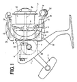
- Fig. 1 shows an overall configuration of the fishing spinning reel
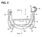
- Fig. 2 shows a rotor portion of the fishing spinning reel
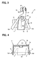
- Fig. 3 is a side view of the rotor as viewed sideways in a direction in which both arm portions face each other
- Fig. 4 is a sectional view taken along the line A-A in Fig. 2
- Fig. 5 is a plan view of the rotor.
- a reel main body 1 of the fishing spinning reel includes a handle 2 which is operated to rotate, a rotor 3 which is driven to rotate in response to a rotation operation of the handle 2, and a spool 5 which is linked with the rotor 3 so that the spool 5 reciprocates in synchronism with the rotational driving of the rotor 3.
- a handle shaft 2a, to which the handle 2 is attached, is supported rotatably within the reel main body 1 via a bearing, and a power transmission mechanism 6 is brought into engagement with the handle shaft 2a so as to transmit rotational operations of the handle 2 to both the rotor 3 and the spool 5.
- the power transmission mechanism 6 includes a drive gear 7 which is attached to the handle shaft 2a so as to rotate together therewith and a rotating tubular shaft 8 which extends in a direction which is at right angles to the handle shaft 2a.
- a pinion 8a is formed at a proximal end side of the rotating tubular shaft 8a so as to mesh with the drive gear 7, and a rotor nut 9 is screwed on a distal end portion of the rotating tubular shaft 8a, whereby the rotor 3 is mounted on the rotating tubular shaft 8.
- a spool shaft 5a is inserted into a front portion of an interior of the rotating tubular shaft 8, and this spool shaft 5a holds the spool 5 around which a line is wound.
- a known oscillating mechanism is coupled to the spool shaft 5a, so that the spool shaft 5a is driven to reciprocate backwards and forwards along an axial direction thereof when the handle shaft 2a rotates in response to rotational operations of the handle 2.
- the rotor 3 is driven to rotate via the drive gear 7 and the pinion 8a (the rotating tubular shaft 8) which meshes with the drive gear 7, while the spool 5 is caused to reciprocate backwards and forwards via the oscillating mechanism.
- a line guide portion is provided on the rotor 3 as will be described in detail below, and a line is uniformly wound around a line winding body portion 5b of the spool 5 via the line guide portion provided on the rotor 3.
- the rotor 3 includes a substantially cylindrical main body portion 3a, and a pair of arm portions 3b are formed on opposite sides of the main body portion 3a so as to be spaced substantially 180° apart from each other.
- the respective arm portions 3b are formed integrally on the main body portion 3a together with connecting portions 3b' which project radially outwards from a rear portion (a reel main body side) of the main body portion 3a, and the arm portions 3b extend in the axial direction.
- gaps are defined between the main body portion 3 and the respective arm portions 3b.
- a skirt portion 5c of the spool 5 is positioned in the gaps.
- support members 3c are supported at distal ends of the pair of arm portions 3b so as to be turned about pivots 3c' between a line winding position and a line reeling-out position.
- a line guide portion (a line roller) 3d is provided at a distal end portion of one of the support members 3c.
- a bail 3e is provided so as to extend between both the support members 3c. The bail 3e picks up a line when the support members 3c are turned from the line reeling-out position to the line winding position and guides the line to the line guide portion 3d.
- a configuration (a bail-less configuration) in which no bail 3e is provided may be adopted.
- a turning and holding mechanism (not shown) is installed in an interior of one of the pair of arm portions 3b. This turning and holding mechanism allows the support members 3c to be selectively turned between the ling winding position and the line reeling-out position and holds the support members 3c in the selected position.
- reinforcement members 10 are provided on the pair of arm portions 3b.
- the reinforcement members 10 extend from side portions of the pair of arm portions 3b towards the rear portion of the main body portion 3a of the rotor 3 and are connected to the main body portion 3a.
- the reinforcement members 10 are preferably provided on both the side portions of each of the pair of arm portions 3b as shown in Fig. 3b .
- the reinforcement members 10 provided on both the side portions of each of the arm portions 3b preferably have substantially the same shape.
- the reinforcement members 10 extend from a front portion (a portion where the support member 3c is provided) towards a proximal portion of the arm portion 3b on the side portions thereof and are gradually spaced away from each other as they so extend.
- the reinforcement members 10 are provided so as to form a substantially inverted V-like shape when viewed sideways in a direction in which both the arm portions 3b face each other, whereby gaps (space portions) G are produced between opposite sides of the proximal portion of the arm portion 3b and the reinforcement members 10. Note that the gaps G gradually expand when the reinforcement members 10 and the arm portion 3b are viewed sideways.
- the reinforcement members 10 are formed so as to extend axially rearwards (or on an axially rearward side) from the front portions of the pair of arm portions 3b to eventually connect the pair of arm portions 3b together while being disposed radially outwards of the main body portion 3a.
- the reinforcement member 10 is formed so as to extend between the pair of arm portions 3b and is formed integrally with the main body portion 3a of the rotor 3 so that an intermediate portion 10A is connected to the rear portion of the main body portion 3a (refer to Figs. 2 and 4 ). Because of this, as shown in Fig. 2 , the reinforcement member 10 is formed to extend continuously between the pair of arm portions 3b without any break and is made convex towards the reel main body side.
- the reinforcement member 10 is curved towards the reel main body side (axially rearwards) between the pair of arm portions 3b. At least a lowest end portion (an area where the intermediate portion 10A exists) of the reinforcement member 10 is designed to be positioned closer to the reel main body side than a rear edge portion (a line denoted by P) of the skirt portion 5c of the spool when the spool 5 reciprocates to be shifted closest to the reel main body side. More specifically, the reinforcement member 10 is positioned so that both sides of a rear end of the skirt 5c partially overlap the reinforcement member 10 when the spool 5 is shifted closes to the reel main body side. Thus, even in the event that the spool 5 reciprocates, the reciprocation of the spool 5 can visually be recognized with ease without being interrupted by the reinforcement member 10.
- the reinforcement members 10 can disperse stress produced by the load so exerted, thereby making it possible to prevent the deformation or the like of the arm portions.
- gap portions like the gaps G can be provided as required by making the reinforcement members 10 into the beam-like construction without increasing the thickness of the proximal portion of the arm portion, it is possible to realize as much a reduction in weight of the rotor as possible while holding the strength of the arm portions.
- the reinforcement members 10 extend between the arm portions 3b so as to be made convex (curved) towards the reel main body 1 while being connected to the rear portion of the main body portion 3a of the rotor 3.
- the reinforcement portions 10 are provided at both the side portions of the arm portions 3b, the reinforcement of the arm portions 3b can be enhanced more effectively, and enhancement in rotational balance of the rotor 3 can be realized.
- both the reinforcement members 10 are spaced away from each other as the reinforcement members 10 extend towards the proximal portion of the arm portion 3b on the side portions thereof so as to form the substantially inverted V-like shape as the reinforcement members 10 and the arm portion 3b are viewed sideways, whereby the arm portion is formed into a so-called tapered shape.
- the curved reinforcement member 10 projects further downwards than a lower edge of the skirt of the spool 5, whereby the shape of the rotor portion is changed, thereby making it possible to enhance the external appearance of the fishing spinning reel.
- the side portions of the arm portions and the rear portion of the main body portion of the rotor are connected by the reinforcement members, even in the event that a large load is exerted on the arm portions by virtue of the tension on the line, the load can be dispersed via the reinforcement members, thereby making it possible to prevent the deformation or the like of the arm portions.
- the reinforcement members are connected to the main body portion of the rotor while being spaced away from the arm portions as they are shifted towards the proximal portions of the arm portions, the increase in thickness of the proximal portions of the arm portions is prevented, thereby making it possible to realize as much a reduction in weight of the rotor as possible.
- the reinforcement members 10 are configured so that the reinforcement members 10 extend from one of the arm portions 3b to connect to the rear portion of the main body portion of the rotor and then extend further to connect to the other arm portion 3b
- a configuration may be adopted in which the reinforcement members 10 extend from one of the arm portions 3b to connect to the rear portion of the main body portion of the rotor but do not extend as far as the other arm portion for connection.
- the configuration may be adopted in which the reinforcement members extend only between one of the arm portions and the rear portion of the main body portion of the rotor.
- one of the arm portions is preferably made to constitute the arm portion on which the line guide portion 3d is provided.
- the front portion of the arm portion 3b to which the reinforcement members 10 are connected denotes a substantially front half portion of the arm portion 3b.
- the reinforcement members 10 preferably extend from the front distal end portion of the arm portion.
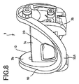
- Figs. 6 to 8 show a fishing spinning reel according to a second embodiment.
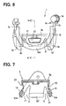
- Fig. 6 shows a portion of the fishing spinning reel which constitutes a rotor thereof
- Fig. 7 is a sectional view taken along the line B-B in Fig. 6
- Fig. 8 is a perspective view of a main part of the rotor shown in Fig. 6 (the perspective view showing a state in which a cover for arm portions is removed).
- openings 20 and cutouts 21 are formed in a main body portion 3a of a rotor 3.
- the openings 20 are formed in confronting positions which lie 90° apart from positions where arm portions 3b are formed, and the cutouts 21, which have a substantially triangular shape, are formed on both sides of each of the openings 20.
- the openings 20 and the cutouts 21 are formed in the different positions from those where the arm portions are formed as shown in Fig. 7 , so as not to reduce the strength of the arm portions 3b.
- Intermediate portions 10A of reinforcement members 10 are connected integrally to respective lower end positions of the openings 20.
- the frame construction is enabled in which the cutout or gap portions exist in the predetermined positions of the main body portion 3a to reduce the weight of the rotor as much as possible while realizing the reinforcement of the arm portions 3b.
- the shapes and forming positions of the openings 20 and the cutouts 21 can be modified as required, and only either the openings 20 or the cutouts 21 may be formed. In addition, in consideration of the external appearance of the fishing spinning reel, the shapes and positions of the openings and cutouts may be changed.
- a waterproof cap K shown in Fig. 1 is attached to a front portion of a reel main body 1 which is disposed within the main body portion 3a of the rotor 3, so that a bearing portion which is provided between the front portion of the reel main body 1 and a tubular rotating shaft 8, and an anti-reverse mechanism can be accommodated in a waterproof fashion.
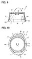
- Figs. 9 and 10 show a fishing spinning reel according to a third embodiment.
- Fig. 9 is a sectional view of a rotor
- Fig. 10 is a plan view of the rotor shown in Fig. 9 .
- curved reinforcement members 10 are spaced apart from the rear portion of the main body portion 3a of the rotor 3 without being connected thereto so as to bridge a space defined between arm portions 3b.
- the reinforcement members are provided to extend between side portions of one of the arm portions and side portions of the other arm portion, even in the event that a large load is exerted on the arm portions by a tension on a line, a dispersion of stress produced on the arm portions is realized, whereby the arm portions are reinforced effectively, the deformation or the like of the arm portions being thereby prevented.
- the reinforcement members are provided to extend between the arm portions so that the reinforcement members are spaced apart from the arm portions as they extend towards proximal portion sides of the arm portions to thereby become convex towards the reel main body side. Because of this, an increase in thickness of proximal portions of the arm portions is prevented, thereby making it possible to realize as much a reduction in weight of the rotor as possible.
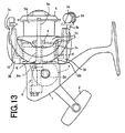
- Figs. 13 to 18 show a fourth embodiment of the invention.
- Fig. 13 shows an overall configuration of a fishing spinning reel
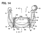
- Fig. 14 shows a portion of the fishing spinning reel where a rotor is provided
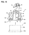
- Fig. 15 is a side view of the rotor shown in Fig. 14 as viewed sideways in a direction in which both arm portions face each other
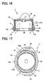
- Fig. 16 is a sectional view taken along the line A-A in Fig. 14
- Fig. 17 is a plan view of the rotor shown in Fig. 14
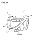
- Fig. 18 is a perspective view of a main part of the rotor shown in Fig. 14 .
- gaps (space portions) G exist on both sides of a proximal portion of each of the arm portions 3b between the sides of the proximal portion and reinforcement members 10.
- the space portions G shown in Fig. 15 gradually expand relative to the proximal portion of the arm portion 3b as the gaps extend towards the proximal portion.
- the line gets slackened rearwards from a line guide portion due to a change in tension on the line or slackness in the line caused during a line winding operation so as to be entangled in the space portions.
- the gaps in the space portions are closed by a closure member, which will be described later, so that the entanglement of the line with the reinforcement members 10 is prevented.
- a closure member 120 is provided on a rotor 3 which closes the space portions G defined between both the sides of the proximal portion of each of the arm portions 3b and the reinforcement members 10.
- the closure member means a member (which may be a portion integrated with the rotor) functioning to prevent the line from entering the portions (the space portions G) indicated by chain double-dashed lines which are produced by the aforesaid reinforcement members 10 being formed to thereby be entangled with the reinforcement members 10.
- the closure member 120 includes a collar-like member (a cylindrical member) which is separate from the rotor 3 and which is installed in an interior of the main body portion 3a of the rotor 3.
- the closure member 120 of this embodiment is formed based on the shape of the main body portion 3a of the rotor 3 and the shape of connecting portions 3b' which project radially outwards from the main body portion.
- the closure member 120 includes a primary cylindrical portion 120a which is closely attached to an inner circumferential surface of the cylindrical main body portion 3a and a secondary cylindrical portion 120b which can closely be attached to radially inward inner surfaces 3b" which are formed on the connecting portions 3b' and which is larger in diameter than the primary cylindrical portion 120a.
- the closure member 120 can be fitted in or press fitted in the main body portion 3a of the rotor in a direction indicated by an arrow in Fig. 15 .
- the closure member 120 can be attached integrally to the rotor 3 by the primary cylindrical portion 120a being bonded to the inner circumferential surface 3a' of the main body portion 3a and part of a circumferential surface of the secondary portion 120b being bonded to the inner surfaces 3b" of the connecting portions 3b'.
- the secondary cylindrical portion 120b of the closure member 120 closes (covers) areas indicated by chain double-dashed lines in Figs. 15 and 16 , whereby the line is prevented from entering these areas to be entangled with the reinforcement members 10.
- the secondary cylindrical portion 120b may be brought into abutment with inner surfaces 10a of the reinforcement members 10 instead of being bonded thereto, or part of the circumferential surface of the secondary cylindrical portion 120b may be bonded to the inner surfaces 10a of the reinforcement members.
- the closure member 120 may elastically be locked on the inner circumferential surface 3a' or on the inner surfaces 3b".
- the closure member 120 is provided on the rotor 3 which covers the space portions G defined between both the sides of the proximal portions of the arm portions 3b and the reinforcement members 10, even in the event that the line is slackened towards the rear portion of the rotor as a result of slackness generated in the line or deflection of the line, the line is prevented from being entangled with the reinforcement members 10 which is provided to bridge the space between the arm portions, whereby the line is prevented from being broken or damaged.
- the line is prevented from being caught on the reinforcement members 10 even during the line winding operation, there is caused no problem with the line winding operation.
- the closure member 120 functions to prevent the line from being caught on the reinforcement members 10 but does not function to reinforce the arm portions 3b
- the closure member 120 is preferably formed of a material whose specific gravity is smaller than that of a material for the rotor 3.
- the closure member 120 is formed of a material such as resin, whereby the rotor can be prevented from getting heavy.
- the closure member 120 may be fixed to the rotor 3 through bonding or may be fixed thereto by means of mechanical members such as screws.
- a waterproof cap K shown in Fig. 13 is attached to a front portion of a reel main body 1 that is disposed within the main body portion 3a of the rotor 3 so that a bearing portion that is provided between the front portion of the reel main body 1 and a tubular rotating shaft 8 and an anti-reverse mechanism can be accommodated in a waterproof fashion.
- the side portions of the arm portions and the rear portion of the main body portion of the rotor are connected together by the reinforcement members, even in the event that a large load is exerted on the arm portions by virtue of a tension on the line, the load so exerted can be dispersed via the reinforcement members, thereby making it possible to prevent the deformation or the like of the arm portions.
- the reinforcement members are spaced apart from the arm portions as they extend towards the proximal portions of the arm portions so as to be connected to the main body portion of the rotor, an increase in thickness of the proximal portions of the arm portions is prevented, thereby making it possible to realize as much a reduction in weight of the rotor as possible.
- the closure member (the cover portion) is provided on the rotor which covers the space portions defined between the proximal portions of the arm portions and the reinforcement members, even in the event that the line is slackened from the ling guide portion as a result of a change in tension on the line or slackness in the line being caused during the line winding operation, there is caused no such situation in which the line gets entangled in the areas where the space portions are defined.
- Figs. 19 to 21 show a fishing spinning reel according to a fifth embodiment.
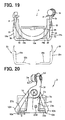
- Fig. 19 shows a portion of the fishing spinning reel where a rotor thereof exists
- Fig. 20 is a side view of the rotor shown in Fig. 19 as viewed sideways in a direction in which both arm portions face each other
- Fig. 21 is a perspective view of a main part of the rotor shown in Fig. 19 .
- the closure member is formed as the separate member (the collar-like member) from the constituent members of the rotor and is designed to be press fitted in the main body portion 3a.
- the closure member may be formed as a part of a member which forms the rotor 3.
- the closure member is integrated with a cover member 23 which is attached to a surface of each arm portion 3b.
- each cover member 23 includes a cover portion 23a which covers the arm portion 3b and a pair of arm portions (closing portions) 23b which extend in an are-like fashion towards circumferential sides at a lower end of the cover portion 23a (in Fig. 21 , only one of the pair of arm portions is shown). Then, the pair of arm portions close (cover) space portions G which are areas indicated by chain double-dashed lines in Fig. 20 so as to prevent the line from entering the areas for entanglement with reinforcement members 10.
- Distal end portions of the arm portions 23b are designed to be brought into abutment with inner surfaces 10a of intermediate portions 10A of reinforcement members 10 when the cover members 23 are attached to the arm portions 3b with screws 23d or the like.
- the arm portion 23b for the other cover member may be fixed to the reinforcement member 10 through bonding or the like.
- the shape thereof can be changed as required.
- the reinforcement member 10 when the reinforcement member 10 is formed so as to be convex towards the reel main body side, the reinforcement member 10 does not necessarily have to be curved but can be formed into a substantially V-like shape which is made up of straight lines as is shown in Fig. 11 .
- the surface of the reinforcement members 10 the surface does not necessarily have to be made into the flat surface but may be configured as shown in Fig. 12 , for example. Namely, a configuration may be adopted in which the intermediate portion of the reinforcement member 10 is made into a thick portion 10B and this thick portion is connected to the rear portion 3a of the rotor 3. By adopting the configuration, an increase in strength at the connecting portion can be realized. Further, the thickness of the reinforcement members 10 can also be changed as required.
- the connecting positions of the reinforcement members 10 to the main body portion of the rotor 3 can also be changed as required as long as the reciprocating motions of the spool 5 are not interrupted.
- reinforcement members are described as being formed continuously so as to bridge the space between the arm portions, a configuration may be adopted, for example, in which the continuity of the reinforcement member is broken at the intermediate portion and the reinforcement member is connected to the main body portion 3a at resulting end portions thereof.
- the closure member may only have to be made to close the space portions G effectively.
- the closure member may be formed as a portion which is integrated with the rotor so as to connect the proximal portions of the arm portions 3b with the intermediate portions 10A of the reinforcement members 10.
- the reinforcement members 10 are described as extending from the front portions of the side portions of the arm portions 3b, the positions where the reinforcement members 10 extend from the arm portions 3b are not limited to the side portions of the arm portions.
- the reinforcement members 10 may extend from any positions on the front portions of the arm portions.
- a configuration may be adopted in which the reinforcement members 10 extend from radially outer circumferential portions of the arm portions 3b.
- one and the other of the reinforcement members are preferably connected together at the radially outer circumferential portions of the arm portions.
Landscapes
- Life Sciences & Earth Sciences (AREA)
- Environmental Sciences (AREA)
- Animal Husbandry (AREA)
- Biodiversity & Conservation Biology (AREA)
Priority Applications (1)
| Application Number | Priority Date | Filing Date | Title |
|---|---|---|---|
| PL10167675T PL2277375T3 (pl) | 2009-06-29 | 2010-06-29 | Wędkarski kołowrotek spinningowy |
Applications Claiming Priority (2)
| Application Number | Priority Date | Filing Date | Title |
|---|---|---|---|
| JP2009153739A JP4939573B2 (ja) | 2009-06-29 | 2009-06-29 | 魚釣用スピニングリール |
| JP2009178215A JP5021699B2 (ja) | 2009-07-30 | 2009-07-30 | 魚釣用スピニングリール |
Publications (2)
| Publication Number | Publication Date |
|---|---|
| EP2277375A1 EP2277375A1 (en) | 2011-01-26 |
| EP2277375B1 true EP2277375B1 (en) | 2013-08-14 |
Family
ID=43216357
Family Applications (1)
| Application Number | Title | Priority Date | Filing Date |
|---|---|---|---|
| EP10167675.7A Active EP2277375B1 (en) | 2009-06-29 | 2010-06-29 | Fishing spinning reel |
Country Status (6)
| Country | Link |
|---|---|
| US (1) | US8033492B2 (pl) |
| EP (1) | EP2277375B1 (pl) |
| KR (1) | KR101182031B1 (pl) |
| CN (1) | CN101933499B (pl) |
| ES (1) | ES2435002T3 (pl) |
| PL (1) | PL2277375T3 (pl) |
Families Citing this family (7)
| Publication number | Priority date | Publication date | Assignee | Title |
|---|---|---|---|---|
| USD661370S1 (en) * | 2011-10-11 | 2012-06-05 | Steve Zock | Reel post |
| JP5995321B2 (ja) | 2013-02-28 | 2016-09-21 | グローブライド株式会社 | 魚釣用スピニングリール |
| JP6389370B2 (ja) * | 2014-03-28 | 2018-09-12 | グローブライド株式会社 | 魚釣用スピニングリール |
| JP7113707B2 (ja) | 2018-09-14 | 2022-08-05 | 株式会社シマノ | スピニングリール |
| CN110637792A (zh) * | 2019-10-25 | 2020-01-03 | 厦门楷铭科技有限公司 | 一种具有感应报警功能的钓鱼卷线器 |
| JP1664452S (pl) * | 2019-12-12 | 2020-07-27 | ||
| JP1664453S (pl) * | 2019-12-12 | 2020-07-27 |
Family Cites Families (8)
| Publication number | Priority date | Publication date | Assignee | Title |
|---|---|---|---|---|
| US4775112A (en) * | 1983-12-07 | 1988-10-04 | Urso Charles L | Apparatus for line casting and reeling with power assisted cast |
| US5199209A (en) * | 1989-11-27 | 1993-04-06 | Wellesley Research Associates, Inc. | Fish hook attachment for fish hook construction |
| US5312067A (en) * | 1991-05-07 | 1994-05-17 | Shimano Inc. | Spinning reel |
| JP2894422B2 (ja) * | 1993-12-22 | 1999-05-24 | ダイワ精工株式会社 | 魚釣用スピニングリール |
| FR2760321B1 (fr) * | 1997-03-06 | 1999-05-07 | Mitchell Sports | Moulinet de peche a arceau de retenue |
| SG104324A1 (en) * | 2001-05-22 | 2004-06-21 | Shimano Kk | Spinning reel rotor |
| JP2003225038A (ja) * | 2002-02-04 | 2003-08-12 | Shimano Inc | スピニングリールのロータ |
| JP3999544B2 (ja) | 2002-03-26 | 2007-10-31 | ダイワ精工株式会社 | 魚釣用スピニングリ−ル |
-
2010
- 2010-06-22 CN CN2010102072167A patent/CN101933499B/zh active Active
- 2010-06-24 KR KR1020100059826A patent/KR101182031B1/ko active Active
- 2010-06-29 EP EP10167675.7A patent/EP2277375B1/en active Active
- 2010-06-29 PL PL10167675T patent/PL2277375T3/pl unknown
- 2010-06-29 US US12/825,804 patent/US8033492B2/en active Active
- 2010-06-29 ES ES10167675T patent/ES2435002T3/es active Active
Also Published As
| Publication number | Publication date |
|---|---|
| CN101933499B (zh) | 2013-08-14 |
| KR20110001910A (ko) | 2011-01-06 |
| PL2277375T3 (pl) | 2014-01-31 |
| CN101933499A (zh) | 2011-01-05 |
| US20100327097A1 (en) | 2010-12-30 |
| KR101182031B1 (ko) | 2012-09-11 |
| US8033492B2 (en) | 2011-10-11 |
| EP2277375A1 (en) | 2011-01-26 |
| ES2435002T3 (es) | 2013-12-18 |
Similar Documents
| Publication | Publication Date | Title |
|---|---|---|
| EP2277375B1 (en) | Fishing spinning reel | |
| CN105025704B (zh) | 钓鱼用旋压式卷线器 | |
| CN107027722B (zh) | 钓鱼用纺车式卷线器 | |
| KR100433369B1 (ko) | 스피닝릴의프레임구조 | |
| CN107439502B (zh) | 单轴承绕线轮 | |
| JP2006042740A (ja) | スピニングリールの釣り糸案内機構 | |
| JP7355522B2 (ja) | 両軸受リール | |
| JP4939573B2 (ja) | 魚釣用スピニングリール | |
| JP2007006710A (ja) | 両軸受リール | |
| JP5021699B2 (ja) | 魚釣用スピニングリール | |
| JP4121869B2 (ja) | スピニングリールのリール本体 | |
| JP3905068B2 (ja) | スピニングリールのロータ | |
| JP2007174939A (ja) | スピニングリールのハンドル取付構造 | |
| US11324207B2 (en) | Dual-bearing reel | |
| JP7391062B2 (ja) | 魚釣用スピニングリール | |
| CN110896935B (zh) | 旋压式绕线轮 | |
| JP5427645B2 (ja) | 魚釣用スピニングリール | |
| KR102603653B1 (ko) | 스피닝 릴 | |
| JP7558088B2 (ja) | 魚釣用スピニングリール | |
| JP7558087B2 (ja) | 魚釣用スピニングリール | |
| JP7384851B2 (ja) | 魚釣用スピニングリール | |
| CN104798746B (zh) | 双轴承绕线轮的绕线轮主体 | |
| KR20170074744A (ko) | 듀얼 베어링 릴 | |
| JP7476126B2 (ja) | 魚釣用スピニングリール | |
| KR20140080408A (ko) | 스피닝 릴 |
Legal Events
| Date | Code | Title | Description |
|---|---|---|---|
| PUAI | Public reference made under article 153(3) epc to a published international application that has entered the european phase |
Free format text: ORIGINAL CODE: 0009012 |
|
| AK | Designated contracting states |
Kind code of ref document: A1 Designated state(s): AL AT BE BG CH CY CZ DE DK EE ES FI FR GB GR HR HU IE IS IT LI LT LU LV MC MK MT NL NO PL PT RO SE SI SK SM TR |
|
| AX | Request for extension of the european patent |
Extension state: BA ME RS |
|
| 17P | Request for examination filed |
Effective date: 20110726 |
|
| 17Q | First examination report despatched |
Effective date: 20120717 |
|
| GRAP | Despatch of communication of intention to grant a patent |
Free format text: ORIGINAL CODE: EPIDOSNIGR1 |
|
| RIN1 | Information on inventor provided before grant (corrected) |
Inventor name: KANEKO, KYOICHI Inventor name: FUJIOKA, MASASHI Inventor name: TSUTSUMI, WATARU Inventor name: SHIBATA, TAKASHI |
|
| GRAS | Grant fee paid |
Free format text: ORIGINAL CODE: EPIDOSNIGR3 |
|
| GRAA | (expected) grant |
Free format text: ORIGINAL CODE: 0009210 |
|
| AK | Designated contracting states |
Kind code of ref document: B1 Designated state(s): AL AT BE BG CH CY CZ DE DK EE ES FI FR GB GR HR HU IE IS IT LI LT LU LV MC MK MT NL NO PL PT RO SE SI SK SM TR |
|
| REG | Reference to a national code |
Ref country code: GB Ref legal event code: FG4D |
|
| REG | Reference to a national code |
Ref country code: CH Ref legal event code: EP Ref country code: AT Ref legal event code: REF Ref document number: 626224 Country of ref document: AT Kind code of ref document: T Effective date: 20130815 |
|
| REG | Reference to a national code |
Ref country code: IE Ref legal event code: FG4D |
|
| REG | Reference to a national code |
Ref country code: DE Ref legal event code: R096 Ref document number: 602010009343 Country of ref document: DE Effective date: 20131010 |
|
| REG | Reference to a national code |
Ref country code: ES Ref legal event code: FG2A Ref document number: 2435002 Country of ref document: ES Kind code of ref document: T3 Effective date: 20131218 |
|
| REG | Reference to a national code |
Ref country code: AT Ref legal event code: MK05 Ref document number: 626224 Country of ref document: AT Kind code of ref document: T Effective date: 20130814 Ref country code: NL Ref legal event code: VDEP Effective date: 20130814 |
|
| REG | Reference to a national code |
Ref country code: LT Ref legal event code: MG4D |
|
| PG25 | Lapsed in a contracting state [announced via postgrant information from national office to epo] |
Ref country code: LT Free format text: LAPSE BECAUSE OF FAILURE TO SUBMIT A TRANSLATION OF THE DESCRIPTION OR TO PAY THE FEE WITHIN THE PRESCRIBED TIME-LIMIT Effective date: 20130814 Ref country code: HR Free format text: LAPSE BECAUSE OF FAILURE TO SUBMIT A TRANSLATION OF THE DESCRIPTION OR TO PAY THE FEE WITHIN THE PRESCRIBED TIME-LIMIT Effective date: 20130814 Ref country code: IS Free format text: LAPSE BECAUSE OF FAILURE TO SUBMIT A TRANSLATION OF THE DESCRIPTION OR TO PAY THE FEE WITHIN THE PRESCRIBED TIME-LIMIT Effective date: 20131214 Ref country code: AT Free format text: LAPSE BECAUSE OF FAILURE TO SUBMIT A TRANSLATION OF THE DESCRIPTION OR TO PAY THE FEE WITHIN THE PRESCRIBED TIME-LIMIT Effective date: 20130814 Ref country code: NO Free format text: LAPSE BECAUSE OF FAILURE TO SUBMIT A TRANSLATION OF THE DESCRIPTION OR TO PAY THE FEE WITHIN THE PRESCRIBED TIME-LIMIT Effective date: 20131114 Ref country code: PT Free format text: LAPSE BECAUSE OF FAILURE TO SUBMIT A TRANSLATION OF THE DESCRIPTION OR TO PAY THE FEE WITHIN THE PRESCRIBED TIME-LIMIT Effective date: 20131216 Ref country code: CY Free format text: LAPSE BECAUSE OF FAILURE TO SUBMIT A TRANSLATION OF THE DESCRIPTION OR TO PAY THE FEE WITHIN THE PRESCRIBED TIME-LIMIT Effective date: 20130918 Ref country code: SE Free format text: LAPSE BECAUSE OF FAILURE TO SUBMIT A TRANSLATION OF THE DESCRIPTION OR TO PAY THE FEE WITHIN THE PRESCRIBED TIME-LIMIT Effective date: 20130814 |
|
| REG | Reference to a national code |
Ref country code: PL Ref legal event code: T3 |
|
| PG25 | Lapsed in a contracting state [announced via postgrant information from national office to epo] |
Ref country code: GR Free format text: LAPSE BECAUSE OF FAILURE TO SUBMIT A TRANSLATION OF THE DESCRIPTION OR TO PAY THE FEE WITHIN THE PRESCRIBED TIME-LIMIT Effective date: 20131115 Ref country code: SI Free format text: LAPSE BECAUSE OF FAILURE TO SUBMIT A TRANSLATION OF THE DESCRIPTION OR TO PAY THE FEE WITHIN THE PRESCRIBED TIME-LIMIT Effective date: 20130814 Ref country code: FI Free format text: LAPSE BECAUSE OF FAILURE TO SUBMIT A TRANSLATION OF THE DESCRIPTION OR TO PAY THE FEE WITHIN THE PRESCRIBED TIME-LIMIT Effective date: 20130814 Ref country code: LV Free format text: LAPSE BECAUSE OF FAILURE TO SUBMIT A TRANSLATION OF THE DESCRIPTION OR TO PAY THE FEE WITHIN THE PRESCRIBED TIME-LIMIT Effective date: 20130814 Ref country code: BE Free format text: LAPSE BECAUSE OF FAILURE TO SUBMIT A TRANSLATION OF THE DESCRIPTION OR TO PAY THE FEE WITHIN THE PRESCRIBED TIME-LIMIT Effective date: 20130814 |
|
| PG25 | Lapsed in a contracting state [announced via postgrant information from national office to epo] |
Ref country code: CY Free format text: LAPSE BECAUSE OF FAILURE TO SUBMIT A TRANSLATION OF THE DESCRIPTION OR TO PAY THE FEE WITHIN THE PRESCRIBED TIME-LIMIT Effective date: 20130814 |
|
| PG25 | Lapsed in a contracting state [announced via postgrant information from national office to epo] |
Ref country code: NL Free format text: LAPSE BECAUSE OF FAILURE TO SUBMIT A TRANSLATION OF THE DESCRIPTION OR TO PAY THE FEE WITHIN THE PRESCRIBED TIME-LIMIT Effective date: 20130814 Ref country code: RO Free format text: LAPSE BECAUSE OF FAILURE TO SUBMIT A TRANSLATION OF THE DESCRIPTION OR TO PAY THE FEE WITHIN THE PRESCRIBED TIME-LIMIT Effective date: 20130814 Ref country code: EE Free format text: LAPSE BECAUSE OF FAILURE TO SUBMIT A TRANSLATION OF THE DESCRIPTION OR TO PAY THE FEE WITHIN THE PRESCRIBED TIME-LIMIT Effective date: 20130814 Ref country code: DK Free format text: LAPSE BECAUSE OF FAILURE TO SUBMIT A TRANSLATION OF THE DESCRIPTION OR TO PAY THE FEE WITHIN THE PRESCRIBED TIME-LIMIT Effective date: 20130814 Ref country code: SK Free format text: LAPSE BECAUSE OF FAILURE TO SUBMIT A TRANSLATION OF THE DESCRIPTION OR TO PAY THE FEE WITHIN THE PRESCRIBED TIME-LIMIT Effective date: 20130814 Ref country code: CZ Free format text: LAPSE BECAUSE OF FAILURE TO SUBMIT A TRANSLATION OF THE DESCRIPTION OR TO PAY THE FEE WITHIN THE PRESCRIBED TIME-LIMIT Effective date: 20130814 |
|
| PLBE | No opposition filed within time limit |
Free format text: ORIGINAL CODE: 0009261 |
|
| STAA | Information on the status of an ep patent application or granted ep patent |
Free format text: STATUS: NO OPPOSITION FILED WITHIN TIME LIMIT |
|
| 26N | No opposition filed |
Effective date: 20140515 |
|
| REG | Reference to a national code |
Ref country code: DE Ref legal event code: R097 Ref document number: 602010009343 Country of ref document: DE Effective date: 20140515 |
|
| PG25 | Lapsed in a contracting state [announced via postgrant information from national office to epo] |
Ref country code: LU Free format text: LAPSE BECAUSE OF FAILURE TO SUBMIT A TRANSLATION OF THE DESCRIPTION OR TO PAY THE FEE WITHIN THE PRESCRIBED TIME-LIMIT Effective date: 20140629 Ref country code: MC Free format text: LAPSE BECAUSE OF FAILURE TO SUBMIT A TRANSLATION OF THE DESCRIPTION OR TO PAY THE FEE WITHIN THE PRESCRIBED TIME-LIMIT Effective date: 20130814 |
|
| REG | Reference to a national code |
Ref country code: CH Ref legal event code: PL |
|
| REG | Reference to a national code |
Ref country code: IE Ref legal event code: MM4A |
|
| PG25 | Lapsed in a contracting state [announced via postgrant information from national office to epo] |
Ref country code: LI Free format text: LAPSE BECAUSE OF NON-PAYMENT OF DUE FEES Effective date: 20140630 Ref country code: CH Free format text: LAPSE BECAUSE OF NON-PAYMENT OF DUE FEES Effective date: 20140630 Ref country code: IE Free format text: LAPSE BECAUSE OF NON-PAYMENT OF DUE FEES Effective date: 20140629 |
|
| PG25 | Lapsed in a contracting state [announced via postgrant information from national office to epo] |
Ref country code: MT Free format text: LAPSE BECAUSE OF FAILURE TO SUBMIT A TRANSLATION OF THE DESCRIPTION OR TO PAY THE FEE WITHIN THE PRESCRIBED TIME-LIMIT Effective date: 20130814 |
|
| PG25 | Lapsed in a contracting state [announced via postgrant information from national office to epo] |
Ref country code: SM Free format text: LAPSE BECAUSE OF FAILURE TO SUBMIT A TRANSLATION OF THE DESCRIPTION OR TO PAY THE FEE WITHIN THE PRESCRIBED TIME-LIMIT Effective date: 20130814 |
|
| REG | Reference to a national code |
Ref country code: FR Ref legal event code: PLFP Year of fee payment: 7 |
|
| PG25 | Lapsed in a contracting state [announced via postgrant information from national office to epo] |
Ref country code: BG Free format text: LAPSE BECAUSE OF FAILURE TO SUBMIT A TRANSLATION OF THE DESCRIPTION OR TO PAY THE FEE WITHIN THE PRESCRIBED TIME-LIMIT Effective date: 20130814 |
|
| PG25 | Lapsed in a contracting state [announced via postgrant information from national office to epo] |
Ref country code: HU Free format text: LAPSE BECAUSE OF FAILURE TO SUBMIT A TRANSLATION OF THE DESCRIPTION OR TO PAY THE FEE WITHIN THE PRESCRIBED TIME-LIMIT; INVALID AB INITIO Effective date: 20100629 Ref country code: TR Free format text: LAPSE BECAUSE OF FAILURE TO SUBMIT A TRANSLATION OF THE DESCRIPTION OR TO PAY THE FEE WITHIN THE PRESCRIBED TIME-LIMIT Effective date: 20130814 |
|
| REG | Reference to a national code |
Ref country code: FR Ref legal event code: PLFP Year of fee payment: 8 |
|
| REG | Reference to a national code |
Ref country code: FR Ref legal event code: PLFP Year of fee payment: 9 |
|
| PG25 | Lapsed in a contracting state [announced via postgrant information from national office to epo] |
Ref country code: MK Free format text: LAPSE BECAUSE OF FAILURE TO SUBMIT A TRANSLATION OF THE DESCRIPTION OR TO PAY THE FEE WITHIN THE PRESCRIBED TIME-LIMIT Effective date: 20130814 |
|
| PG25 | Lapsed in a contracting state [announced via postgrant information from national office to epo] |
Ref country code: AL Free format text: LAPSE BECAUSE OF FAILURE TO SUBMIT A TRANSLATION OF THE DESCRIPTION OR TO PAY THE FEE WITHIN THE PRESCRIBED TIME-LIMIT Effective date: 20130814 |
|
| P01 | Opt-out of the competence of the unified patent court (upc) registered |
Effective date: 20230414 |
|
| PGFP | Annual fee paid to national office [announced via postgrant information from national office to epo] |
Ref country code: GB Payment date: 20240509 Year of fee payment: 15 |
|
| PGFP | Annual fee paid to national office [announced via postgrant information from national office to epo] |
Ref country code: IT Payment date: 20240513 Year of fee payment: 15 Ref country code: FR Payment date: 20240509 Year of fee payment: 15 |
|
| PGFP | Annual fee paid to national office [announced via postgrant information from national office to epo] |
Ref country code: PL Payment date: 20240516 Year of fee payment: 15 |
|
| PGFP | Annual fee paid to national office [announced via postgrant information from national office to epo] |
Ref country code: ES Payment date: 20240702 Year of fee payment: 15 |
|
| PGFP | Annual fee paid to national office [announced via postgrant information from national office to epo] |
Ref country code: DE Payment date: 20250507 Year of fee payment: 16 |