EP2276262A2 - Bildaufnahmevorrichtung mit einem Lichtdurchlassfilter - Google Patents
Bildaufnahmevorrichtung mit einem Lichtdurchlassfilter Download PDFInfo
- Publication number
- EP2276262A2 EP2276262A2 EP10167725A EP10167725A EP2276262A2 EP 2276262 A2 EP2276262 A2 EP 2276262A2 EP 10167725 A EP10167725 A EP 10167725A EP 10167725 A EP10167725 A EP 10167725A EP 2276262 A2 EP2276262 A2 EP 2276262A2
- Authority
- EP
- European Patent Office
- Prior art keywords
- light receiving
- light transmissive
- light
- receiving device
- sections
- Prior art date
- Legal status (The legal status is an assumption and is not a legal conclusion. Google has not performed a legal analysis and makes no representation as to the accuracy of the status listed.)
- Granted
Links
- 238000003384 imaging method Methods 0.000 claims abstract description 57
- 230000010287 polarization Effects 0.000 claims description 76
- 230000003595 spectral effect Effects 0.000 description 36
- 238000006073 displacement reaction Methods 0.000 description 28
- 238000003672 processing method Methods 0.000 description 13
- 239000011159 matrix material Substances 0.000 description 11
- 230000035945 sensitivity Effects 0.000 description 10
- 238000000926 separation method Methods 0.000 description 8
- 238000010586 diagram Methods 0.000 description 5
- 230000005540 biological transmission Effects 0.000 description 3
- 239000000853 adhesive Substances 0.000 description 2
- 239000003086 colorant Substances 0.000 description 2
- 230000012447 hatching Effects 0.000 description 2
- 238000004519 manufacturing process Methods 0.000 description 2
- 230000008033 biological extinction Effects 0.000 description 1
- 230000000295 complement effect Effects 0.000 description 1
- 230000007423 decrease Effects 0.000 description 1
- 238000009826 distribution Methods 0.000 description 1
- 230000002708 enhancing effect Effects 0.000 description 1
- 229910044991 metal oxide Inorganic materials 0.000 description 1
- 150000004706 metal oxides Chemical class 0.000 description 1
- 238000012986 modification Methods 0.000 description 1
- 230000004048 modification Effects 0.000 description 1
- 230000003287 optical effect Effects 0.000 description 1
- 238000002360 preparation method Methods 0.000 description 1
- 239000004065 semiconductor Substances 0.000 description 1
- 238000000411 transmission spectrum Methods 0.000 description 1
Images


Classifications
-
- G—PHYSICS
- G02—OPTICS
- G02B—OPTICAL ELEMENTS, SYSTEMS OR APPARATUS
- G02B27/00—Optical systems or apparatus not provided for by any of the groups G02B1/00 - G02B26/00, G02B30/00
- G02B27/28—Optical systems or apparatus not provided for by any of the groups G02B1/00 - G02B26/00, G02B30/00 for polarising
-
- H—ELECTRICITY
- H04—ELECTRIC COMMUNICATION TECHNIQUE
- H04N—PICTORIAL COMMUNICATION, e.g. TELEVISION
- H04N23/00—Cameras or camera modules comprising electronic image sensors; Control thereof
- H04N23/10—Cameras or camera modules comprising electronic image sensors; Control thereof for generating image signals from different wavelengths
- H04N23/12—Cameras or camera modules comprising electronic image sensors; Control thereof for generating image signals from different wavelengths with one sensor only
Definitions
- the disclosures herein relate to an imaging apparatus that is provided with a light transmissive filter having a plurality of polarizing filters or color separation filters arranged therein, and that produces image signals by imaging an object.
- an imaging apparatus takes an image of an object to produce image signals, and may separate the image signals into image data of different wavelength bands.
- an imaging apparatus takes an image of an object to produce image signals, and may separate the image signals into image data of different polarization components. This may be performed for the purpose of enhancing the contrast of the imaged object by removing unnecessary polarization components.
- Such imaging apparatuses may use a light receiving device array in which light receiving devices of the same type are arranged, and may separate incoming light into light components having different polarization directions or different wavelength bands.
- an area-divided-type filter that has its entire area divided into plural types, each allowing the passage of light having a different characteristic, may be disposed in front of a light receiving device array such as a CCD (Charge Coupled Device), a CMOS (Complementary Metal Oxide Semiconductor), or the like. Signal processing is then performed on image signal data output from the light receiving devices. With this arrangement, a plurality of image signals are obtained as if light receiving devices of different types corresponding to light transmissive filters of respective, different characteristics were provided.
- a light receiving device array such as a CCD (Charge Coupled Device), a CMOS (Complementary Metal Oxide Semiconductor), or the like.
- Signal processing is then performed on image signal data output from the light receiving devices.
- a plurality of image signals are obtained as if light receiving devices of different types corresponding to light transmissive filters of respective, different characteristics were provided.
- a color filter may be disposed in front of a light receiving device array such as a CCD.
- This color filter may include spectral filters (hereinafter referred to as "spectral filter sections”) having different light transmission wavelength bands disposed in a predetermined arrangement pattern as in the case of a color separation filter (i.e., area-divided spectral filter), in which areas are divided into R (red), G (green), and B (blue).
- spectral filter sections spectral filters having different light transmission wavelength bands disposed in a predetermined arrangement pattern as in the case of a color separation filter (i.e., area-divided spectral filter), in which areas are divided into R (red), G (green), and B (blue).
- the light receiving device array is used to produce image signal data of respective colors.
- Such a configuration is disclosed in Japanese Patent Application Publication No. 2007-086720 , for example.
- a polarizing filter may be disposed in front of a light receiving device array such as a CCD.
- This polarizing filter may be an area-divided polarizing filter that includes plural polarizing filters (hereinafter referred to as "polarizing filter sections") having different polarization directions disposed in a predetermined arrangement pattern.
- polarizing filter sections plural polarizing filters having different polarization directions disposed in a predetermined arrangement pattern.
- a single image signal obtained by imaging an object is separated according to polarization directions to produce plural image signals.
- the imaging apparatuses as described above have the following problems.
- light received by a single light receiving device corresponding to a single pixel of an image needs to have passed only through one of the plural light transmissive filters (hereinafter referred to as "light transmissive filter sections").
- the shape and size of each light receiving device need to match the shape and size of each light transmissive filter section if the light receiving devices are provided in one-to-one correspondence to the light transmissive filter sections.
- a light transmissive filter provided as a separate unit is attached by an adhesive agent or the like to the front face of a light receiving device array such as a CCD or CMOS. Accordingly, the provision of filter sections having shapes and sizes that match those of the light receiving devices alone is not sufficient. There is an additional requirement that the light transmissive filter sections need to be accurately aligned with the light receiving array.
- a single light receiving device may receive light through plural polarizing filter sections having different polarization characteristics.
- the image signal data output from this light receiving device is different from what is intended as polarized image data. Polarized image data may not be obtained at all depending on the ratio of mixing of lights.
- the light transmissive filter is displaced by rotation relative to the light receiving devices, such a displacement may be regarded as a parallel displacement in a small area of interest for a small rotation angle. In the same manner as described above, such an arrangement gives rise to a problem in that polarization information may not be properly obtained.
- an imaging apparatus that can reproduce image signal data corresponding to respective light transmissive filter sections even when the accuracy of alignment of the light transmissive filter disposed in front of light receiving devices is not sufficient.
- an imaging apparatus includes a light receiving device array having light receiving devices two-dimensionally arranged in both a row direction and a column direction, and a light transmissive filter disposed in front of the light receiving device array, wherein the light transmissive filter includes plural types of band-shape light transmissive sections having respective, different light transmissive characteristics, and the plural types of band-shape light transmissive sections are arranged in sequence in a width direction thereof.
- an imaging apparatus includes a light receiving device array having light receiving devices two-dimensionally arranged in both a row direction and a column direction, and a light transmissive filter disposed in front of the light receiving device array, wherein the light transmissive filter includes plural types of band-shape light transmissive sections having respective, different light transmissive characteristics, and the plural types of band-shape light transmissive sections are arranged in sequence in a width direction thereof, wherein a direction perpendicular to a border line between the light transmissive sections is parallel to neither the row direction nor the column direction in which the light receiving devices are arranged, and wherein a width of the light transmissive sections as measured in the row direction in which the light receiving devices are arranged is substantially equal to a width of one light receiving device as measured in the row direction.
- an imaging apparatus includes a light receiving device array having light receiving devices two-dimensionally arranged in both a row direction and a column direction; a light transmissive filter disposed in front of the light receiving device array, and an arithmetic processing unit configured to perform arithmetic processing on image data output from the light receiving devices, wherein the light transmissive filter includes plural types of band-shape light transmissive sections having respective, different light transmissive characteristics, and the plural types of band-shape light transmissive sections are arranged in sequence in a width direction thereof, and wherein the arithmetic processing is performed to obtain a weighted sum of image data output from a plurality of light receiving devices by using weight factors calculated in advance.
- an imaging apparatus in which a light transmissive filter having different types of light transmissive sections is disposed in front of light receiving devices can reproduce image data corresponding to the respective light transmissive sections over the entire area of the image even when the accuracy of alignment of the light transmissive filter relative to the light receiving devices is not sufficient.
- the imaging apparatus of the present embodiment takes an image of an object once by using a pair of a light receiving device array and an area-divided polarizing filter.
- the imaging device then reconstructs two image data corresponding to the vertical polarization component and the horizontal polarization component, respectively, from the obtained original image data.
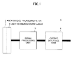
- Fig. 1 is a block diagram schematically illustrating the entire configuration of the imaging apparatus according to the present embodiment.
- an imaging apparatus 5 of the present embodiment includes a light receiving device array 1, an area-divided polarizing filter 2, a signal processing unit 3, and an output interface unit 4.
- the area-divided polarizing filter 2 and the signal processing unit 3 serve as a light transmissive filter and an arithmetic processing unit, respectively.
- the light receiving device array 1 has light receiving devices arranged two-dimensionally in rows and columns.
- a CCD, MOS, CMOS, or the like may be used as the light receiving device array 1.
- the area-divided polarizing filter 2 is situated in front of the light receiving device array 1 on an optical path through which the light receiving device array 1 receives light.
- the signal processing unit 3 receives image data output from the light receiving device array 1, and produces image data that are equivalent to data obtained through respective, separate polarizing filters.
- Polarizing filter sections of the present embodiment serve as light transmissive sections.
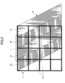
- Fig. 2 is a drawing illustrating an arrangement pattern of the polarizing filter sections of the area-divided polarizing filter that is provided in the imaging apparatus according to the present embodiment.
- the area-divided polarizing filter 2 includes band-shape polarizing filter sections of different types that allow the selective passage of lights having respective, different polarization directions.
- the area-divided polarizing filter 2 includes polarizing filter sections 21 and 22 of different types that allow the selective passage of lights having different polarization directions that are at 90-degree angles relative to each other.
- the two types of diagonal bands illustrated in Fig. 2 are the two types of polarizing filter sections 21 and 22 that correspond to the vertical direction and the horizontal direction, respectively.
- the two types of polarizing filter sections 21 and 22 are arranged alternately (i.e., in sequence) in a width direction.
- the polarizing filter section 21 may be a vertical polarization filter section for which the polarization direction is vertical.
- the polarizing filter section 22 may be a horizontal polarization filter section for which the polarization direction is horizontal.
- the phrase "arranged in sequence" means that the two types A and B are arranged in the order as follows: A, B, A, B, A, B, and so on.
- the area-divided polarizing filter is not limited to the configuration in which two types of polarizing filter sections for transmitting vertically polarized light and horizontally polarized light are provided.
- the area-divided polarizing filter may have three or more types of polarizing filter sections having different polarization directions.
- the phrase "arranged in sequence" means that the three types A, B, and C are arranged in the order as follows: A, B, C, A, B, C, A, B, C, and so on.
- the area-divided polarizing filter 2 is positioned as illustrated in Fig. 2 if the area-divided polarizing filter 2 is not misaligned with the light receiving device array 1. Namely, the area-divided polarizing filter 2 is situated to have a predetermined positional relationship as described below with light receiving devices 10 (or the light receiving sections of the light receiving devices 10), which are squares arranged in a matrix form.
- each of the vertical polarization filter section 21 and the horizontal polarization filter section 22 has a width that is equal to the width of one light receiving device (i.e., one pixel) in the horizontal direction in Fig. 2 .
- the width of the vertical polarization filter section 21 and the width of the horizontal polarization filter section 22 as measured in the row direction in which the rows of the light receiving devices 10 extend are substantially equal to the width of one light receiving device 10 in the row direction.
- each of the vertical polarization filter section 21 and the horizontal polarization filter section 22 has a width that is equal to the total width of two pixels in the vertical direction in Fig. 2 .
- the width of the vertical polarization filter section 21 and the width of the horizontal polarization filter section 22 as measured in the column direction in which the columns of the light receiving devices 10 extend are substantially twice the width of one light receiving device 10 in the column direction.
- the border line between the adjacent polarizing filter sections of the area-divided polarizing filter has a slope equal to 2.
- the border line is diagonally positioned such that the border line crosses two light receiving devices (i.e., two pixels) in the vertical direction while it crosses one light receiving device (i.e., one pixel) in the horizontal direction.
- the arrangement pattern in which the band-shape polarizing filter sections are arranged is a diagonal stripe pattern.
- the width direction in which the band-shape polarizing filter sections are arranged is parallel to neither the horizontal direction (i.e., row direction) of the light receiving device array nor the vertical direction (i.e., column direction) of the light receiving device array.
- the term "width direction" refers to a direction that is perpendicular to the border line.
- the row direction and the column direction merely refer to the two arrangement directions of a two-dimensional array, respectively, and are interchangeable with each other.
- the configuration of the present embodiment thus includes an arrangement that is obtained through 90-degree rotation in which the column direction and the row direction are swapped with each other.
- the present embodiment includes a configuration that is obtained by replacing the horizontal direction (i.e., row direction) and the vertical direction (i.e., column direction) with the vertical direction (i.e., column direction) and the horizontal direction (i.e., row direction), respectively.
- Figs. 3A through 3D and Fig. 4 will be referred to in order to explain how the arrangement pattern of the polarizing filter sections of the area-divided polarizing filter according to the present embodiment is robust against the misalignment that occurs between the polarizing filter sections and the light receiving devices.
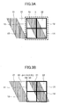
- Figs. 3A through 3D are drawings illustrating examples of misalignments in the horizontal direction (i.e., row direction) between the polarizing filter sections and the light receiving devices.
- Fig. 4 is a graph chart illustrating a cover rate that indicates the size of the overlapping area between a given polarizing filter section and a given light receiving device as a proportion of the area size of the given polarizing filter section with respect to various displacements in the horizontal direction (i.e., row direction).
- Fig. 4 illustrates a cover rate between the vertical polarization filter section and a given light receiving device.
- Fig. 3A, Fig. 3B , Fig. 3C, and Fig. 3D illustrate d being 0 pixel, d being 1/4 pixels (0.25 pixels), d being 1/2 pixels (0.5 pixels), and d being 3/4 pixels (0.75 pixels in the horizontal direction (i.e., row direction)), respectively.
- Fig. 3A, Fig. 3B , Fig. 3C, and Fig. 3D for the sake of simplicity of illustration, four light receiving devices 11 through 14 arranged in two rows and two columns are illustrated with the vertical polarization filter section 21 and the horizontal polarization filter section 22 overlapping these light receiving devices 11 through 14.
- the area enclosed by dotted lines II in Fig. 3A corresponds to the area enclosed by dotted lines I in Fig. 2 .
- the vertical polarization filter section 21 is shown in hatching whereas the horizontal polarization filter section 22 is not shown in hatching in Figs. 3A through 3D .
- the light receiving devices 14 and 12 among the light receiving devices 11 through 14 will be described first. Specifically, a description will be given of the cover rate that indicates the size of the overlapping area between the light receiving devices 14 and 12 and the vertical polarization filter section 21 in Figs. 3A through 3D .
- the cover rates of the light receiving devices 14 and 12 with respect to the vertical polarization filter section 21 are 0.75 and 0.25, respectively.
- the cover rates of the light receiving devices 14 and 12 with respect to the vertical polarization filter section 21 are 0.875 and 0.5, respectively.
- the displacement d between the polarizing filter sections and the light receiving devices being 1/2 (0.5) as illustrated in Fig.
- the cover rates of the light receiving devices 14 and 12 with respect to the vertical polarization filter section 21 are 0.75 and 0.75, respectively.
- the cover rates of the light receiving devices 14 and 12 with respect to the vertical polarization filter section 21 are 0.5 and 0.875, respectively.
- Fig. 4 illustrates changes in the cover rate with respect to continuous changes in the displacement d.
- the horizontal axis represents the displacement d in the horizontal direction (i.e., row direction) between the polarizing filter sections and the light receiving devices.
- One unit of the horizontal axis is equal to the width of one light receiving device in the horizontal direction (i.e., row direction).
- the vertical axis represents the cover rate of one light receiving device with respect to the vertical polarization filter section 21.
- a dashed-line curve C1, a solid-line curve C2, a chain-line curve C3, and a dotted-line curve C4 correspond to the light receiving devices 11, 12, 13, and 14 illustrated in Fig. 3A , respectively.
- the cover rate of the vertical polarization filter section 21 indicated by the curve C4 is in the range exceeding 0.75 with respect to the range of the displacement d being 0 to 0.5. Namely, 75% or more of the area of the light receiving device 14 is covered by the vertical polarization filter section 21.
- the curve C4 is downward sloping from left to right in the range of the displacement d being 0.5 to 1.0. Namely, the cover rate of the vertical polarization filter section 21 with respect to the light receiving device 14 decreases with an increase in the displacement d.
- the cover rate of the vertical polarization filter section 21 indicated by the curve C2 is in the range exceeding 0.75 with respect to the range of the displacement d being 0.5 to 1.0.
- the vertical polarization filter section 21 75% or more of the area of the light receiving device 12 is covered by the vertical polarization filter section 21.
- the curves C4 and C2 in the range of the displacement d being 1.0 to 2.0 have the shape that are obtained by flipping the curves C4 and C2 in the range of the displacement d being 0 to 1.0 upside down with respect to a line of symmetry that is the horizontal line situated at a cover rate of 0.5.
- the areas of the light receiving devices 14 and 12 that are not covered by the vertical polarization filter section 21 are covered by the horizontal polarization filter section 22. In the range of the displacement d being 1.0 to 2.0, thus, the cover rate of the horizontal polarization filter section 22 is 75 % or more.
- the light receiving devices 14 and 12 are vertically adjacent to each other.
- the light receiving device 12 on the upper side is covered half by the vertical polarization filter section 21 and half by the horizontal polarization filter section 22 (i.e., when the displacement d is 0.25)
- the light receiving device 14 on the lower side is mainly covered by the vertical polarization filter section 21.
- the light receiving device 14 on the lower side is covered half by the vertical polarization filter section 21 and half by the horizontal polarization filter section 22 (i.e., when the displacement d is 0.75)
- the light receiving device 12 on the upper side is mainly covered by the vertical polarization filter section 21.
- the cover rate of the light receiving device on the right-hand side with respect to coverage by one polarizing filter section is the same as the cover rate of the light receiving device on the left-hand side with respect to coverage by the other polarizing filter section.
- a vicinity area comprised of the four pixels arranged in a 2-pixel-by-2-pixel matrix i.e., in two rows and two columns
- one of these four pixels is mainly covered (i.e., with a cover rate of 0.75 or more) by the vertical polarization filter section 21
- another pixel is mainly covered (i.e., with a cover rate of 0.75 or more) by the horizontal polarization filter section 22. This is true for any displacement d.
- FIG. 5 is a drawing illustrating an example in which the arrangement pattern of an area-divided polarizing filter is a checker board pattern, and is displaced by 1/2 (0.5) in the horizontal direction (i.e., row direction) and in the vertical direction (i.e., column direction), respectively, relative to the light receiving devices.
- Each light receiving device may have a width of 6 micrometers in both the horizontal direction (i.e., row direction) and the vertical direction (i.e., column direction).
- the polarizing filter sections are then displaced relative to the light receiving devices by 3 micrometers (i.e., 1/2 pixels) in the horizontal direction and the vertical direction.
- Fig. 5 four light receiving devices 111, 112, 113, and 114 and four polarizing filter sections are illustrated.
- the four polarizing filter sections include vertical polarization filter sections 121a and 121b and horizontal polarization filter sections 122a and 122b. In the state illustrated in Fig.
- the light received by the light receiving device 114 is an average of lights passing through the four polarizing filter sections 121a, 121b, 122a, and 122b.
- the output of the light receiving device 114 becomes substantially constant regardless of what polarization direction the incoming light has. No information about polarization can thus be obtained.
- the same positional relationships between the light receiving devices and the polarizing filter sections continue in the horizontal direction (i.e., row direction) and in the vertical direction (i.e., column direction). Accordingly, in all the light receiving devices, in addition to the light receiving device 114, the received light becomes an average of the lights passing through the four polarizing filter sections. No information about polarization can thus be obtained.
- neither the cover rate by the vertical polarization filter section nor the cover rate by the horizontal polarization filter section becomes the same in all the four light receiving devices corresponding to the vicinity area comprised of a 2-pixel-by-2-pixel matrix according to the present embodiment. This is true regardless of the displacement d between the light receiving devices and the polarizing filter sections.
- the combination of four pixel outputs is bound to change. Information about polarization can thus be obtained.
- the slope of a border line between adjacent polarizing filter sections relative to a border line between adjacent light receiving devices may be set to a value that is different from 2.
- the width of the filter section in the horizontal direction is one pixel, however, the width of the filter section in the vertical direction becomes 2 pixels.
- This arrangement provides a repetition of the same arrangement in every two pixels in the vertical direction. Such an arrangement can thus help to use a narrow vicinity area, thereby preventing effective resolution from being reduced. Also, such an arrangement can reduce the amount of computation performed by an arithmetic processing unit, which will be described later.
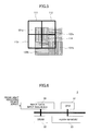
- Fig. 6 is a block diagram illustrating the configuration of the signal processing unit of the imaging apparatus according to the present embodiment.
- the arrangement pattern in which the band-shape polarizing filter sections are arranged is a diagonal stripe pattern. Namely, the arrangement pattern in which the band-shape polarizing filter sections are arranged is the diagonal stripe pattern previously described.
- the width direction in which the band-shape polarizing filter sections are arranged is parallel to neither the horizontal direction (i.e., row direction) of the light receiving device array nor the vertical direction (i.e., column direction) of the light receiving device array.
- the diagonal stripe pattern is employed as the arrangement pattern of the area-divided polarizing filter. This prevents polarization information from being unobtainable when the polarizing filter is misaligned with the light receiving device array.
- one polarizing filter section does not coincide with one light receiving device. Rather, a plurality of polarizing filter sections coincides with one light receiving device. Because of this, image data including only the light component passing through only one polarizing filter section cannot be obtained in a straightforward manner.
- This signal processing method reconstructs plural types of image data corresponding to respective types of polarizing filter sections from image data obtained by taking an image of an object by use of the diagonal stripe arrangement pattern in the area-divided polarizing filter.
- the signal processing unit 3 includes a CPU 31, a DRAM 32, a nonvolatile memory such as a flash memory 33, and an image data input interface 34.
- the signal processing unit 3 executes programs stored in the nonvolatile memory by use of the CPU 31 and the DRAM 32. With this provision, the signal processing unit 3 performs signal processing on the image data received from a light receiving device array through the image data input interface. Data obtained by the signal processing is sent to an output interface unit.
- signal processing is performed by use of software running on the CPU 31.
- Such signal processing may alternatively be performed by a hardware-implemented arithmetic processing circuit.
- Fig. 7 is a flowchart illustrating the signal processing method performed by the imaging apparatus according to the present embodiment.
- the signal processing method of the present embodiment includes a sensitivity measuring step (step S11), a weight factor calculating step (step S12), a weight factor recording step (step S13), an image data acquiring step (step S14), a weighted sum calculating step (step S15), and an image data reconstructing step (step S16).
- step S11 through step S13 are performed in advance. Then, step S14 through step S16 are performed at the time of taking an image of an object.
- the sensitivity measuring step (step S11) is performed in advance.
- polarized light (100% polarization) inclusive of only the vertically polarized light component or only the horizontally polarized light component is shone on the light receiving device array, and image data output from the light receiving device array is input into the signal processing unit.
- the light receiving device array with the area-divided polarizing filter attached thereto is prepared in advance.
- the area-divided polarizing filter may be attached to a face of the light receiving device array by an adhesive agent.
- the positioning, including angular alignment, of the polarizing filter sections of the area-divided polarizing filter relative to the light receiving devices of the light receiving device array does not have to be precise, and may suffice if approximate matching is achieved.
- the light receiving device array with the area-divided polarizing filter attached thereto is combined with the signal processing unit and the output interface unit to prepare the imaging apparatus of the present embodiment.
- the values of the reference image data RI1 and RI2 with respect to a given light receiving device are proportional to the sensitivities of this light receiving device (i.e., pixel) with respect to vertically polarized light and horizontally polarized light, respectively.
- the sensitivities for vertically polarized light and horizontally polarized light are mainly determined by the cover rates of this light receiving device (i.e., pixel) with respect to the vertical polarization filter section and the horizontal polarization filter section, respectively. These sensitivities do not vary after the area-divided polarizing filter is fixedly mounted to the light receiving device array.
- step S12 The weight factor calculating step (step S12) is then performed.
- the signal processing unit calculates weight factors corresponding to respective light receiving devices based on the acquired image data.
- the calculation of the weight factors is performed by using formula (5), which will be described later.
- the weight factor recording step (step S13) is performed.
- the calculated weight factors are stored in memory.
- the memory for storing the weight factors may be the nonvolatile memory such as the flash memory 33.
- step S14 through step S16 are performed at the time of taking an image of an object.
- step S14 the image data acquiring step (step S14) is performed.
- an image of an object is taken to produce image data.
- step S15 the weighted sum calculating step (step S15) is performed.
- arithmetic processing is performed to obtain a weighted sum from the acquired image data by using the stored weight factors.
- the vertically polarized light component of incident light is denoted as L v
- the horizontally polarized light component denoted as L h
- the sensitivity of the vertically polarized light component of a light receiving device i denoted a vi
- the sensitivity of the horizontally polarized light component denoted as a hi
- I i a vi ⁇ L v + a hi ⁇ L h
- I 11 I 12 I 13 I 14 a v ⁇ 11 a v ⁇ 12 a v ⁇ 13 a v ⁇ 14 a h ⁇ 11 a h ⁇ 12 a h ⁇ 13 a h ⁇ 14 ⁇ L v L h
- the intensity I i of incident light is determined from the image data output from the light receiving device array.
- the sensitivities a vi and a hi of vertically and horizontally polarized light components of the light receiving device i are known from the data measured in step S11. Only the polarized light components L v and L h of the incident light are unknown.
- the equation (3) represents simultaneous linear equations in which the number of constraint conditions is larger than the number of unknown values L v and L h .
- the matrix M + is calculated for all the light receiving devices by using the equation (5) in step S12, and the calculated matrix M + is then stored in memory in step S13.
- the calculation of the equation (5) is rather complicated. However, it suffices to perform the calculation of the equation (5) only once prior to an actual imaging operation. Namely, it suffices to perform the calculation only once at the time of manufacturing the camera by using a computer separate from the camera to store the results of calculation in memory. The complexity of the calculation thus does not affect the processing speed at the time of taking an image.
- step S16 image data is reconstructed from the obtained weighted sum, followed by sending the reconstructed image data to the output interface unit.
- the polarizing filter sections having a special arrangement pattern is combined with the signal processing to reconstruct plural image data corresponding to the respective polarizing filter sections over the entire area of the image.
- Such reconstruction is achieved even when the accuracy of alignment is not sufficient upon attaching the area-divided polarizing filter to the light receiving device array. Since there is no need to ensure high precision for positional alignment, the manufacturing cost of the imaging apparatus can be reduced.
- the imaging apparatus of the present embodiment can minimize an area of reference used for performing the arithmetic processing to reconstruct image data. This can prevent effective resolution from being reduced, and can also reduce the amount of computation. Since image data is reconstructed by performing simple arithmetic processing, sufficient processing speed at the time of taking an image is achieved. Moreover, the cost of hardware can be reduced. With the use of a proper polarizing filter, plural polarized light images can be taken at once.
- weight factors for the intensities of incident light are obtained from the sensitivities of each light receiving device for vertically and horizontally polarized light components, and such sensitivities are determined based on image data obtained by actually taking an image of a polarized light source or the like.
- the obtained weight factors reflect variations in various characteristics such as the polarization extinction ratio of each polarizing filter sections, light leakage at borders between the polarizing filter sections, and the like, in addition to variation in the cover rate.
- the signal processing method of the present embodiment can thus correct variations in various characteristics in addition to variations in the cover rate.
- the present embodiment employs an area-divided polarizing filter that has two types of polarizing filter sections, i.e., the vertical polarization filter section and the horizontal polarization filter section, which are arranged alternately.
- the polarizing filter sections are not limited to these two types corresponding to the vertical and horizontal polarizations, but may have a configuration in which three or more polarizing filter sections having three or more different polarization directions are arranged in sequence in a repeated manner.
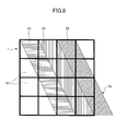
- Fig. 8 is a drawing illustrating an arrangement pattern of the spectral filter sections of the area-divided spectral filter that is provided in the imaging apparatus according to the present embodiment.
- Fig. 8 three types of spectral filter sections are illustrated.
- One spectral filter section is illustrated for each type.
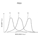
- Fig. 9 is a drawing illustrating the wavelength bands of lights that pass through respective color separation filters constituting the spectral filter sections.
- the imaging apparatus differs from the imaging apparatus of the first embodiment in that a spectral filter is used in place of a polarizing filter.
- the vertical polarization filter section and the horizontal polarization filter section are arranged alternately in the width direction.
- spectral filter sections 23, 24, and 25 comprised of three types of spectral filters having respective spectral transmission characteristics are arranged in sequence in the width direction as illustrated in Fig. 8 .
- the three types of spectral filters may include a first filter F1, a second filter F2, and a third filter F3 having three types of respective transmission wavelength bands as illustrated in Fig. 9 .
- These spectral filters may constitute a color separation filter that allows the passage of RGB colors separately from each other.
- a color separation filter is regarded as a spectral filter in a broader sense, and a description will be given of a spectral filter.
- a spectral filter is used in place of the polarizing filter that is used in the imaging apparatus of the first embodiment.
- the configurations of the light receiving device array, the signal processing unit, and the output interface unit are the same as those described in connection with the block diagram illustrated in Fig. 1 in reference to the first embodiment.
- the signal processing unit of the present embodiment serves as the arithmetic processing unit.
- the area-divided spectral filter and the spectral filter sections of the present embodiment serve as a light transmissive filter and light transmissive sections, respectively.
- each filter section of an area-divided spectral filter 2a of the imaging apparatus has a width equal to the width of one pixel in the horizontal direction (i.e., row direction) as in the first embodiment.
- the border lines between the spectral filter sections 23, 24, and 25 of the area-divided spectral filter 2a have a slope equal to 2.
- the three types of spectral filter sections 23, 24, and 25 are the first filter F1, the second filter F2, and the third filter F3, respectively, which are arranged in sequence in a repeated manner in the width direction.
- the shape of the spectral filter sections 23, 24, and 25 is substantially the same as the shape of the polarizing filter sections 21 and 22 used in the first embodiment.
- Changes in the cover rate with respect to changes in the displacement are substantially the same as those of the polarizing filter sections of the first embodiment described in connection with Fig. 4 .
- the signal processing method of the imaging apparatus is also substantially the same as the signal processing method used in the first embodiment.
- a reference image may be produced by taking an image of an object having uniform luminance with respect to each of the three types of spectral distribution.
- an area of reference is comprised of four light receiving devices (i.e., pixels) having two rows and two columns inclusive of a light receiving device of interest.
- an area of reference is comprised of 6 light receiving devices (i.e., pixels) having two rows and three columns.
- the matrix M appearing in the equation (3) described in the first embodiment is replaced with a matrix M having 6 rows and 2 columns.
- the pseudo inverse matrix M + is obtained by use of the equation (5) described in the first embodiment.
- each spectral filter section may properly be selected, so that a camera for producing spectral images having special spectral characteristics, such as images in the infrared region, may be provided.
- a proper spectral filter plural spectral images can be taken at once.
- the light transmissive filter may include light transmissive sections for transmitting lights that differ from each other in at least one of the three characteristics of light, i.e., wavelength, amplitude (i.e., intensity), and wave vibration direction (i.e., polarization direction).
- the light transmissive filter of the first embodiment provides different light transmissive characteristics that allow the selective passage of lights different from each other in the vibration direction (i.e., polarization direction).
- the light transmissive filter of the second embodiment provides different light transmissive characteristics that allow the selective passage of lights different from each other in the wavelength.
- the light transmissive filter may provide different light transmissive characteristics that allow the selective passage of lights different from each other in the intensity (i.e., amplitude).
Landscapes
- Physics & Mathematics (AREA)
- General Physics & Mathematics (AREA)
- Optics & Photonics (AREA)
- Engineering & Computer Science (AREA)
- Multimedia (AREA)
- Signal Processing (AREA)
- Polarising Elements (AREA)
- Studio Devices (AREA)
- Blocking Light For Cameras (AREA)
- Optical Filters (AREA)
- Color Television Image Signal Generators (AREA)
- Optical Elements Other Than Lenses (AREA)
- Photometry And Measurement Of Optical Pulse Characteristics (AREA)
Applications Claiming Priority (1)
| Application Number | Priority Date | Filing Date | Title |
|---|---|---|---|
| JP2009159965A JP5446521B2 (ja) | 2009-07-06 | 2009-07-06 | 撮像装置 |
Publications (3)
| Publication Number | Publication Date |
|---|---|
| EP2276262A2 true EP2276262A2 (de) | 2011-01-19 |
| EP2276262A3 EP2276262A3 (de) | 2015-04-15 |
| EP2276262B1 EP2276262B1 (de) | 2017-08-09 |
Family
ID=42320833
Family Applications (1)
| Application Number | Title | Priority Date | Filing Date |
|---|---|---|---|
| EP10167725.0A Not-in-force EP2276262B1 (de) | 2009-07-06 | 2010-06-29 | Bildaufnahmevorrichtung mit einem Lichtdurchlassfilter |
Country Status (3)
| Country | Link |
|---|---|
| US (1) | US8462435B2 (de) |
| EP (1) | EP2276262B1 (de) |
| JP (1) | JP5446521B2 (de) |
Families Citing this family (14)
| Publication number | Priority date | Publication date | Assignee | Title |
|---|---|---|---|---|
| IL201110A (en) | 2009-09-22 | 2014-08-31 | Vorotec Ltd | Apparatus and method for navigation |
| JP5310483B2 (ja) * | 2009-10-28 | 2013-10-09 | 株式会社リコー | 撮像装置 |
| US8964072B2 (en) * | 2010-02-25 | 2015-02-24 | Vorotec Ltd. | Light filter with varying polarization angles and processing algorithm |
| US9800805B2 (en) * | 2011-02-02 | 2017-10-24 | The Boeing Company | Frequency selective imaging system |
| JP5708099B2 (ja) * | 2011-03-18 | 2015-04-30 | 株式会社リコー | 画像処理装置、及び画像処理方法 |
| JP5863005B2 (ja) * | 2011-09-01 | 2016-02-16 | 株式会社リコー | 撮像装置 |
| JP5867806B2 (ja) * | 2011-09-16 | 2016-02-24 | 株式会社リコー | 撮像装置及びこれを用いた物体識別装置 |
| JP5929338B2 (ja) * | 2012-03-09 | 2016-06-01 | 株式会社リコー | 撮像装置、分光情報作成方法 |
| US9955802B2 (en) | 2015-04-08 | 2018-05-01 | Fasteners For Retail, Inc. | Divider with selectively securable track assembly |
| JP6264349B2 (ja) | 2015-09-16 | 2018-01-24 | トヨタ自動車株式会社 | 車両前部構造 |
| CN106226856A (zh) * | 2016-08-03 | 2016-12-14 | 京东方科技集团股份有限公司 | 一种偏振片及显示装置 |
| US10473903B2 (en) * | 2017-12-28 | 2019-11-12 | Waymo Llc | Single optic for low light and high light level imaging |
| US20220011588A1 (en) * | 2018-11-26 | 2022-01-13 | Kabushiki Kaisha Tokai Rika Denki Seisakusho | Display board and display device |
| JP7795758B2 (ja) * | 2020-12-09 | 2026-01-08 | 国立大学法人宇都宮大学 | フィルタ、撮像装置及び撮像システム |
Citations (2)
| Publication number | Priority date | Publication date | Assignee | Title |
|---|---|---|---|---|
| JP3771054B2 (ja) | 1998-07-01 | 2006-04-26 | 株式会社リコー | 画像処理装置及び画像処理方法 |
| JP2007086720A (ja) | 2005-08-23 | 2007-04-05 | Photonic Lattice Inc | 偏光イメージング装置 |
Family Cites Families (28)
| Publication number | Priority date | Publication date | Assignee | Title |
|---|---|---|---|---|
| JPS51132832A (en) * | 1975-05-13 | 1976-11-18 | Fuji Photo Film Co Ltd | Correction filters automatic control device |
| JPS57188188A (en) * | 1981-05-14 | 1982-11-19 | Matsushita Electric Ind Co Ltd | Solid-state color image pickup device |
| EP0143357B1 (de) * | 1983-10-31 | 1988-06-08 | Matsushita Electric Industrial Co., Ltd. | Dokumentenabtaster und optische Vorrichtung dafür |
| DE3515020A1 (de) * | 1984-04-28 | 1985-11-07 | Kabushiki Kaisha Toshiba, Kawasaki, Kanagawa | Ortsfrequenzfilter |
| US4737621A (en) * | 1985-12-06 | 1988-04-12 | Adaptive Optics Assoc., Inc. | Integrated adaptive optical wavefront sensing and compensating system |
| US5283634A (en) * | 1987-06-18 | 1994-02-01 | Canon Kabushiki Kaisha | Luminance signal correcting method |
| JP2892177B2 (ja) * | 1991-05-15 | 1999-05-17 | 日本放送協会 | カラー固体撮像装置 |
| JPH0755561A (ja) * | 1993-08-12 | 1995-03-03 | Fujitsu Ltd | 光検知装置 |
| US6327085B1 (en) * | 1998-03-31 | 2001-12-04 | Nikon Corporation | Optical filter and optical device provided with this optical filter |
| JP4027079B2 (ja) * | 2001-11-02 | 2007-12-26 | キヤノン株式会社 | 撮像装置 |
| US7196829B2 (en) * | 2002-01-10 | 2007-03-27 | Micron Technology Inc. | Digital image system and method for combining sensing and image processing on sensor with two-color photo-detector |
| US6940061B2 (en) * | 2002-02-27 | 2005-09-06 | Agilent Technologies, Inc. | Two-color photo-detector and methods for demosaicing a two-color photo-detector array |
| US7098442B2 (en) * | 2003-03-05 | 2006-08-29 | Raytheon Company | Thin micropolarizing filter, and a method for making it |
| JP2005259750A (ja) * | 2004-03-09 | 2005-09-22 | Fuji Film Microdevices Co Ltd | 多板式カラー固体撮像装置及びデジタルカメラ |
| JP4304483B2 (ja) * | 2004-03-24 | 2009-07-29 | 住友金属鉱山株式会社 | 分光素子 |
| EP1758404A4 (de) * | 2004-05-26 | 2010-10-27 | Acutelogic Corp | Abbildungseinrichtung |
| DE102004033602A1 (de) * | 2004-07-08 | 2006-02-16 | Carl Zeiss Sms Gmbh | Abbildungssystem zur Emulation hochaperturiger Scannersysteme |
| US7545422B2 (en) * | 2004-10-27 | 2009-06-09 | Aptina Imaging Corporation | Imaging system |
| JP4902112B2 (ja) * | 2004-11-22 | 2012-03-21 | キヤノン株式会社 | 低域通過フィルタおよび撮像装置 |
| US20060268357A1 (en) * | 2005-05-25 | 2006-11-30 | Vook Dietrich W | System and method for processing images using centralized image correction data |
| JP2007110588A (ja) * | 2005-10-17 | 2007-04-26 | Funai Electric Co Ltd | 複眼撮像装置 |
| US7667747B2 (en) * | 2006-03-15 | 2010-02-23 | Qualcomm Incorporated | Processing of sensor values in imaging systems |
| US20080002255A1 (en) * | 2006-07-02 | 2008-01-03 | Amon Tavor | Stereoscopic Display Using a Color Parallax Barrier |
| US7655898B2 (en) * | 2006-11-30 | 2010-02-02 | Cambridge Research & Instrumentation, Inc. | Optical filter assembly with selectable bandwidth and rejection |
| JP4930109B2 (ja) * | 2007-03-06 | 2012-05-16 | ソニー株式会社 | 固体撮像装置、撮像装置 |
| WO2008149489A1 (ja) * | 2007-05-31 | 2008-12-11 | Panasonic Corporation | 画像処理装置 |
| JP2009049117A (ja) * | 2007-08-17 | 2009-03-05 | Fujifilm Corp | 固体撮像素子のカラーフィルタ形成方法及び固体撮像素子、並びに固体撮像素子用パターンマスクセット |
| US8303195B2 (en) * | 2007-12-26 | 2012-11-06 | Hitachi, Ltd. | Optical transceiver module |
-
2009
- 2009-07-06 JP JP2009159965A patent/JP5446521B2/ja not_active Expired - Fee Related
-
2010
- 2010-06-23 US US12/821,328 patent/US8462435B2/en not_active Expired - Fee Related
- 2010-06-29 EP EP10167725.0A patent/EP2276262B1/de not_active Not-in-force
Patent Citations (2)
| Publication number | Priority date | Publication date | Assignee | Title |
|---|---|---|---|---|
| JP3771054B2 (ja) | 1998-07-01 | 2006-04-26 | 株式会社リコー | 画像処理装置及び画像処理方法 |
| JP2007086720A (ja) | 2005-08-23 | 2007-04-05 | Photonic Lattice Inc | 偏光イメージング装置 |
Also Published As
| Publication number | Publication date |
|---|---|
| EP2276262B1 (de) | 2017-08-09 |
| US8462435B2 (en) | 2013-06-11 |
| JP5446521B2 (ja) | 2014-03-19 |
| EP2276262A3 (de) | 2015-04-15 |
| US20110002040A1 (en) | 2011-01-06 |
| JP2011013630A (ja) | 2011-01-20 |
Similar Documents
| Publication | Publication Date | Title |
|---|---|---|
| US8462435B2 (en) | Imaging apparatus with light transmissive filter | |
| EP2330811B1 (de) | Bildgebungsvorrichtung mit lichtdurchlässigem Filter | |
| KR102718698B1 (ko) | 3d 이미지화 시스템 및 방법 | |
| US8908087B2 (en) | Multiband camera, and multiband image capturing method | |
| JP3821614B2 (ja) | 画像入力装置 | |
| JP6536877B2 (ja) | 撮像装置および撮像システム | |
| US20090021598A1 (en) | Miniature integrated multispectral/multipolarization digital camera | |
| US20180075615A1 (en) | Imaging device, subject information acquisition method, and computer program | |
| US6417950B1 (en) | Three-color imaging on each pixel for increased resolution | |
| US10126709B2 (en) | Apparatus and method for performing in-line lens-free digital holography of an object | |
| CN104025580A (zh) | 彩色摄像元件及摄像装置 | |
| JP3706159B2 (ja) | カラー重ね合せ誤差の補正方法及び装置 | |
| KR101125842B1 (ko) | 3파장 디지털 홀로그래픽 현미경의 자료처리 방법 | |
| US7742087B2 (en) | Image pickup device | |
| CN113766107B (zh) | 用于生成高分辨率图像的方法和设备 | |
| US10931936B2 (en) | Plenoptic sub aperture view shuffling for a richer color sampling | |
| CN111149347A (zh) | 摄像装置及图像处理装置 | |
| EP3547022B1 (de) | Bildaufnahmevorrichtung und bildaufnahmeverfahren | |
| JP2004085965A (ja) | 立体撮像装置および立体表示装置 | |
| TWI861862B (zh) | 多光譜光學感測器、攝影機系統及視差補償方法 | |
| JP2011124795A (ja) | 撮像装置、撮像方法及びこの撮像方法を実行させるためのプログラムを記録したコンピュータ読み取り可能な記録媒体 | |
| KR20210026204A (ko) | 내부전반사 (tir)홀로그램에 의한 고화질 영상 마스크 | |
| CN120769182A (zh) | 一种少像素探测成像方法与装置 | |
| JPS6124876B2 (de) | ||
| DE102012024223A1 (de) | Verfahren und Vorrichtung zum Projizieren eines Musters auf ein Objekt |
Legal Events
| Date | Code | Title | Description |
|---|---|---|---|
| PUAI | Public reference made under article 153(3) epc to a published international application that has entered the european phase |
Free format text: ORIGINAL CODE: 0009012 |
|
| 17P | Request for examination filed |
Effective date: 20100629 |
|
| AK | Designated contracting states |
Kind code of ref document: A2 Designated state(s): AL AT BE BG CH CY CZ DE DK EE ES FI FR GB GR HR HU IE IS IT LI LT LU LV MC MK MT NL NO PL PT RO SE SI SK SM TR |
|
| AX | Request for extension of the european patent |
Extension state: BA ME RS |
|
| PUAL | Search report despatched |
Free format text: ORIGINAL CODE: 0009013 |
|
| AK | Designated contracting states |
Kind code of ref document: A3 Designated state(s): AL AT BE BG CH CY CZ DE DK EE ES FI FR GB GR HR HU IE IS IT LI LT LU LV MC MK MT NL NO PL PT RO SE SI SK SM TR |
|
| AX | Request for extension of the european patent |
Extension state: BA ME RS |
|
| RIC1 | Information provided on ipc code assigned before grant |
Ipc: H04N 9/04 20060101AFI20150309BHEP Ipc: H04N 9/07 20060101ALI20150309BHEP |
|
| RBV | Designated contracting states (corrected) |
Designated state(s): AL AT BE BG CH CY CZ DE DK EE ES FI FR GB GR HR HU IE IS IT LI LT LU LV MC MK MT NL NO PL PT RO SE SI SK SM TR |
|
| 17Q | First examination report despatched |
Effective date: 20160909 |
|
| REG | Reference to a national code |
Ref country code: DE Ref legal event code: R079 Ref document number: 602010044212 Country of ref document: DE Free format text: PREVIOUS MAIN CLASS: H04N0009040000 Ipc: H04N0005225000 |
|
| GRAP | Despatch of communication of intention to grant a patent |
Free format text: ORIGINAL CODE: EPIDOSNIGR1 |
|
| RIC1 | Information provided on ipc code assigned before grant |
Ipc: H04N 9/07 20060101ALI20170201BHEP Ipc: H04N 5/225 20060101AFI20170201BHEP Ipc: H04N 9/04 20060101ALI20170201BHEP |
|
| INTG | Intention to grant announced |
Effective date: 20170220 |
|
| GRAS | Grant fee paid |
Free format text: ORIGINAL CODE: EPIDOSNIGR3 |
|
| GRAA | (expected) grant |
Free format text: ORIGINAL CODE: 0009210 |
|
| AK | Designated contracting states |
Kind code of ref document: B1 Designated state(s): AL AT BE BG CH CY CZ DE DK EE ES FI FR GB GR HR HU IE IS IT LI LT LU LV MC MK MT NL NO PL PT RO SE SI SK SM TR |
|
| REG | Reference to a national code |
Ref country code: GB Ref legal event code: FG4D |
|
| REG | Reference to a national code |
Ref country code: CH Ref legal event code: EP Ref country code: AT Ref legal event code: REF Ref document number: 917998 Country of ref document: AT Kind code of ref document: T Effective date: 20170815 |
|
| REG | Reference to a national code |
Ref country code: IE Ref legal event code: FG4D |
|
| REG | Reference to a national code |
Ref country code: DE Ref legal event code: R096 Ref document number: 602010044212 Country of ref document: DE |
|
| REG | Reference to a national code |
Ref country code: NL Ref legal event code: MP Effective date: 20170809 |
|
| REG | Reference to a national code |
Ref country code: LT Ref legal event code: MG4D |
|
| REG | Reference to a national code |
Ref country code: AT Ref legal event code: MK05 Ref document number: 917998 Country of ref document: AT Kind code of ref document: T Effective date: 20170809 |
|
| PG25 | Lapsed in a contracting state [announced via postgrant information from national office to epo] |
Ref country code: HR Free format text: LAPSE BECAUSE OF FAILURE TO SUBMIT A TRANSLATION OF THE DESCRIPTION OR TO PAY THE FEE WITHIN THE PRESCRIBED TIME-LIMIT Effective date: 20170809 Ref country code: NO Free format text: LAPSE BECAUSE OF FAILURE TO SUBMIT A TRANSLATION OF THE DESCRIPTION OR TO PAY THE FEE WITHIN THE PRESCRIBED TIME-LIMIT Effective date: 20171109 Ref country code: LT Free format text: LAPSE BECAUSE OF FAILURE TO SUBMIT A TRANSLATION OF THE DESCRIPTION OR TO PAY THE FEE WITHIN THE PRESCRIBED TIME-LIMIT Effective date: 20170809 Ref country code: SE Free format text: LAPSE BECAUSE OF FAILURE TO SUBMIT A TRANSLATION OF THE DESCRIPTION OR TO PAY THE FEE WITHIN THE PRESCRIBED TIME-LIMIT Effective date: 20170809 Ref country code: NL Free format text: LAPSE BECAUSE OF FAILURE TO SUBMIT A TRANSLATION OF THE DESCRIPTION OR TO PAY THE FEE WITHIN THE PRESCRIBED TIME-LIMIT Effective date: 20170809 Ref country code: AT Free format text: LAPSE BECAUSE OF FAILURE TO SUBMIT A TRANSLATION OF THE DESCRIPTION OR TO PAY THE FEE WITHIN THE PRESCRIBED TIME-LIMIT Effective date: 20170809 Ref country code: FI Free format text: LAPSE BECAUSE OF FAILURE TO SUBMIT A TRANSLATION OF THE DESCRIPTION OR TO PAY THE FEE WITHIN THE PRESCRIBED TIME-LIMIT Effective date: 20170809 |
|
| PG25 | Lapsed in a contracting state [announced via postgrant information from national office to epo] |
Ref country code: GR Free format text: LAPSE BECAUSE OF FAILURE TO SUBMIT A TRANSLATION OF THE DESCRIPTION OR TO PAY THE FEE WITHIN THE PRESCRIBED TIME-LIMIT Effective date: 20171110 Ref country code: ES Free format text: LAPSE BECAUSE OF FAILURE TO SUBMIT A TRANSLATION OF THE DESCRIPTION OR TO PAY THE FEE WITHIN THE PRESCRIBED TIME-LIMIT Effective date: 20170809 Ref country code: LV Free format text: LAPSE BECAUSE OF FAILURE TO SUBMIT A TRANSLATION OF THE DESCRIPTION OR TO PAY THE FEE WITHIN THE PRESCRIBED TIME-LIMIT Effective date: 20170809 Ref country code: IS Free format text: LAPSE BECAUSE OF FAILURE TO SUBMIT A TRANSLATION OF THE DESCRIPTION OR TO PAY THE FEE WITHIN THE PRESCRIBED TIME-LIMIT Effective date: 20171209 Ref country code: BG Free format text: LAPSE BECAUSE OF FAILURE TO SUBMIT A TRANSLATION OF THE DESCRIPTION OR TO PAY THE FEE WITHIN THE PRESCRIBED TIME-LIMIT Effective date: 20171109 Ref country code: PL Free format text: LAPSE BECAUSE OF FAILURE TO SUBMIT A TRANSLATION OF THE DESCRIPTION OR TO PAY THE FEE WITHIN THE PRESCRIBED TIME-LIMIT Effective date: 20170809 |
|
| PG25 | Lapsed in a contracting state [announced via postgrant information from national office to epo] |
Ref country code: RO Free format text: LAPSE BECAUSE OF FAILURE TO SUBMIT A TRANSLATION OF THE DESCRIPTION OR TO PAY THE FEE WITHIN THE PRESCRIBED TIME-LIMIT Effective date: 20170809 Ref country code: CZ Free format text: LAPSE BECAUSE OF FAILURE TO SUBMIT A TRANSLATION OF THE DESCRIPTION OR TO PAY THE FEE WITHIN THE PRESCRIBED TIME-LIMIT Effective date: 20170809 Ref country code: DK Free format text: LAPSE BECAUSE OF FAILURE TO SUBMIT A TRANSLATION OF THE DESCRIPTION OR TO PAY THE FEE WITHIN THE PRESCRIBED TIME-LIMIT Effective date: 20170809 |
|
| REG | Reference to a national code |
Ref country code: DE Ref legal event code: R097 Ref document number: 602010044212 Country of ref document: DE |
|
| PG25 | Lapsed in a contracting state [announced via postgrant information from national office to epo] |
Ref country code: SM Free format text: LAPSE BECAUSE OF FAILURE TO SUBMIT A TRANSLATION OF THE DESCRIPTION OR TO PAY THE FEE WITHIN THE PRESCRIBED TIME-LIMIT Effective date: 20170809 Ref country code: EE Free format text: LAPSE BECAUSE OF FAILURE TO SUBMIT A TRANSLATION OF THE DESCRIPTION OR TO PAY THE FEE WITHIN THE PRESCRIBED TIME-LIMIT Effective date: 20170809 Ref country code: SK Free format text: LAPSE BECAUSE OF FAILURE TO SUBMIT A TRANSLATION OF THE DESCRIPTION OR TO PAY THE FEE WITHIN THE PRESCRIBED TIME-LIMIT Effective date: 20170809 Ref country code: IT Free format text: LAPSE BECAUSE OF FAILURE TO SUBMIT A TRANSLATION OF THE DESCRIPTION OR TO PAY THE FEE WITHIN THE PRESCRIBED TIME-LIMIT Effective date: 20170809 |
|
| PLBE | No opposition filed within time limit |
Free format text: ORIGINAL CODE: 0009261 |
|
| STAA | Information on the status of an ep patent application or granted ep patent |
Free format text: STATUS: NO OPPOSITION FILED WITHIN TIME LIMIT |
|
| REG | Reference to a national code |
Ref country code: FR Ref legal event code: PLFP Year of fee payment: 9 |
|
| 26N | No opposition filed |
Effective date: 20180511 |
|
| PG25 | Lapsed in a contracting state [announced via postgrant information from national office to epo] |
Ref country code: SI Free format text: LAPSE BECAUSE OF FAILURE TO SUBMIT A TRANSLATION OF THE DESCRIPTION OR TO PAY THE FEE WITHIN THE PRESCRIBED TIME-LIMIT Effective date: 20170809 |
|
| REG | Reference to a national code |
Ref country code: CH Ref legal event code: PL |
|
| REG | Reference to a national code |
Ref country code: BE Ref legal event code: MM Effective date: 20180630 |
|
| PG25 | Lapsed in a contracting state [announced via postgrant information from national office to epo] |
Ref country code: LU Free format text: LAPSE BECAUSE OF NON-PAYMENT OF DUE FEES Effective date: 20180629 Ref country code: MC Free format text: LAPSE BECAUSE OF FAILURE TO SUBMIT A TRANSLATION OF THE DESCRIPTION OR TO PAY THE FEE WITHIN THE PRESCRIBED TIME-LIMIT Effective date: 20170809 |
|
| REG | Reference to a national code |
Ref country code: IE Ref legal event code: MM4A |
|
| PG25 | Lapsed in a contracting state [announced via postgrant information from national office to epo] |
Ref country code: IE Free format text: LAPSE BECAUSE OF NON-PAYMENT OF DUE FEES Effective date: 20180629 Ref country code: CH Free format text: LAPSE BECAUSE OF NON-PAYMENT OF DUE FEES Effective date: 20180630 Ref country code: LI Free format text: LAPSE BECAUSE OF NON-PAYMENT OF DUE FEES Effective date: 20180630 |
|
| PG25 | Lapsed in a contracting state [announced via postgrant information from national office to epo] |
Ref country code: BE Free format text: LAPSE BECAUSE OF NON-PAYMENT OF DUE FEES Effective date: 20180630 |
|
| PG25 | Lapsed in a contracting state [announced via postgrant information from national office to epo] |
Ref country code: MT Free format text: LAPSE BECAUSE OF NON-PAYMENT OF DUE FEES Effective date: 20180629 |
|
| PG25 | Lapsed in a contracting state [announced via postgrant information from national office to epo] |
Ref country code: TR Free format text: LAPSE BECAUSE OF FAILURE TO SUBMIT A TRANSLATION OF THE DESCRIPTION OR TO PAY THE FEE WITHIN THE PRESCRIBED TIME-LIMIT Effective date: 20170809 |
|
| PG25 | Lapsed in a contracting state [announced via postgrant information from national office to epo] |
Ref country code: PT Free format text: LAPSE BECAUSE OF FAILURE TO SUBMIT A TRANSLATION OF THE DESCRIPTION OR TO PAY THE FEE WITHIN THE PRESCRIBED TIME-LIMIT Effective date: 20170809 Ref country code: HU Free format text: LAPSE BECAUSE OF FAILURE TO SUBMIT A TRANSLATION OF THE DESCRIPTION OR TO PAY THE FEE WITHIN THE PRESCRIBED TIME-LIMIT; INVALID AB INITIO Effective date: 20100629 |
|
| PG25 | Lapsed in a contracting state [announced via postgrant information from national office to epo] |
Ref country code: MK Free format text: LAPSE BECAUSE OF NON-PAYMENT OF DUE FEES Effective date: 20170809 Ref country code: CY Free format text: LAPSE BECAUSE OF FAILURE TO SUBMIT A TRANSLATION OF THE DESCRIPTION OR TO PAY THE FEE WITHIN THE PRESCRIBED TIME-LIMIT Effective date: 20170809 |
|
| PG25 | Lapsed in a contracting state [announced via postgrant information from national office to epo] |
Ref country code: AL Free format text: LAPSE BECAUSE OF FAILURE TO SUBMIT A TRANSLATION OF THE DESCRIPTION OR TO PAY THE FEE WITHIN THE PRESCRIBED TIME-LIMIT Effective date: 20170809 |
|
| PGFP | Annual fee paid to national office [announced via postgrant information from national office to epo] |
Ref country code: DE Payment date: 20210618 Year of fee payment: 12 Ref country code: FR Payment date: 20210622 Year of fee payment: 12 |
|
| PGFP | Annual fee paid to national office [announced via postgrant information from national office to epo] |
Ref country code: GB Payment date: 20210625 Year of fee payment: 12 |
|
| REG | Reference to a national code |
Ref country code: DE Ref legal event code: R079 Ref document number: 602010044212 Country of ref document: DE Free format text: PREVIOUS MAIN CLASS: H04N0005225000 Ipc: H04N0023000000 |
|
| REG | Reference to a national code |
Ref country code: DE Ref legal event code: R119 Ref document number: 602010044212 Country of ref document: DE |
|
| GBPC | Gb: european patent ceased through non-payment of renewal fee |
Effective date: 20220629 |
|
| PG25 | Lapsed in a contracting state [announced via postgrant information from national office to epo] |
Ref country code: FR Free format text: LAPSE BECAUSE OF NON-PAYMENT OF DUE FEES Effective date: 20220630 |
|
| PG25 | Lapsed in a contracting state [announced via postgrant information from national office to epo] |
Ref country code: GB Free format text: LAPSE BECAUSE OF NON-PAYMENT OF DUE FEES Effective date: 20220629 Ref country code: DE Free format text: LAPSE BECAUSE OF NON-PAYMENT OF DUE FEES Effective date: 20230103 |