EP2276166B1 - Kompaktes FPGA-basiertes digitales Motorsteuergerät - Google Patents
Kompaktes FPGA-basiertes digitales Motorsteuergerät Download PDFInfo
- Publication number
- EP2276166B1 EP2276166B1 EP10251247.2A EP10251247A EP2276166B1 EP 2276166 B1 EP2276166 B1 EP 2276166B1 EP 10251247 A EP10251247 A EP 10251247A EP 2276166 B1 EP2276166 B1 EP 2276166B1
- Authority
- EP
- European Patent Office
- Prior art keywords
- fpga
- compact
- motor controller
- based digital
- commutation
- Prior art date
- Legal status (The legal status is an assumption and is not a legal conclusion. Google has not performed a legal analysis and makes no representation as to the accuracy of the status listed.)
- Active
Links
Images

Classifications
-
- H—ELECTRICITY
- H02—GENERATION; CONVERSION OR DISTRIBUTION OF ELECTRIC POWER
- H02P—CONTROL OR REGULATION OF ELECTRIC MOTORS, ELECTRIC GENERATORS OR DYNAMO-ELECTRIC CONVERTERS; CONTROLLING TRANSFORMERS, REACTORS OR CHOKE COILS
- H02P6/00—Arrangements for controlling synchronous motors or other dynamo-electric motors using electronic commutation dependent on the rotor position; Electronic commutators therefor
- H02P6/14—Electronic commutators
- H02P6/16—Circuit arrangements for detecting position
- H02P6/17—Circuit arrangements for detecting position and for generating speed information
-
- H—ELECTRICITY
- H02—GENERATION; CONVERSION OR DISTRIBUTION OF ELECTRIC POWER
- H02P—CONTROL OR REGULATION OF ELECTRIC MOTORS, ELECTRIC GENERATORS OR DYNAMO-ELECTRIC CONVERTERS; CONTROLLING TRANSFORMERS, REACTORS OR CHOKE COILS
- H02P6/00—Arrangements for controlling synchronous motors or other dynamo-electric motors using electronic commutation dependent on the rotor position; Electronic commutators therefor
- H02P6/34—Modelling or simulation for control purposes
Definitions
- the subject matter disclosed herein generally relates to digital motor controllers, and more particularly to compact field programmable gate array (FPGA) based digital motor controllers.
- FPGA compact field programmable gate array
- a brushless direct current (DC) motor can use switches to electrically control commutation.
- One or more sensors can be used to determine position or speed information for feedback control of the brushless DC motor.
- commutation control may be non-linear with respect to rotational speed of the motor. Non-linear period information complicates control logic, which can result in demanding mathematical calculations and complex algorithms for accurate control.
- control logic typically requires a microprocessor and accompanying computer system control elements, such as non-volatile memory, volatile memory, arbitration logic, operating system software, and application software in the motor control loop.
- the use of a microprocessor and computer system control elements may be unsuitable for certain environments that are geometrically constrained and/or subject to harsh environmental conditions, for instance, high radiation environments.
- the present invention provides a compact field programmable gate array (FPGA)-based digital motor controller comprising: a sensor interface implemented in hardware circuitry configured to receive sensor data from one or more sensors which provide position information for a direct current (DC) brushless motor and to generate conditioned sensor data; a commutation control implemented in hardware circuitry configured to create switching commands to control commutation for the DC brushless motor, the commutation control generating commutation pulses from the conditioned sensor data of the sensor interface, which are formatted as time values indicating an elapsed time between a common position of the DC brushless motor or multiple positions of the DC brushless motor; and a time inverter implemented in hardware circuitry configured to receive the commutation pulses from the commutation control and convert the commutation pulses into a rotational speed of the DC brushless motor by performing a mathematical inversion of the time values to provide a linear feedback control parameter.
- FPGA compact field programmable gate array
- the present invention provides a method for providing a compact field programmable gate array (FPGA)-based digital motor controller comprising: receiving sensor data from one or more sensors indicating position information for a direct current (DC) brushless motor; generating conditioned sensor data at a sensor interface implemented in hardware circuitry of the compact FPGA-based digital motor controller; generating commutation pulses from the conditioned sensor data at a commutation control implemented in hardware circuitry of the compact FPGA-based digital motor controller, the commutation pulses being formatted as time values indicating an elapsed time between a common position of the DC brushless motor or multiple positions of the DC brushless motor; converting the commutation pulses into a rotational speed of the DC brushless motor by performing a mathematical inversion of the time values at a time inverter implemented in hardware circuitry of the compact FPGA-based digital motor controller to provide a linear feedback control parameter; and creating switching commands at the commutation control to control commutation for the DC brushless
- FIG. 1 illustrates a block diagram of an exemplary embodiment of a system 100 with a compact field programmable gate array (FPGA)-based digital motor controller 102.
- the compact FPGA-based digital motor controller 102 receives input data from one or more sensors 104 via sensor data link 106.
- the one or more sensors 104 may be Hall effect sensors that detect magnetic field changes due to rotation of a direct current (DC) brushless motor 108.
- the one or more sensors 104 produce timing pulses responsive to a rotational position of the DC brushless motor 108.
- Motor drive transistors 110 switch a drive voltage source 112 onto motor drive link 114, providing switched current to establish commutation for the DC brushless motor 108.
- Switch commands are driven from the compact FPGA-based digital motor controller 102 to the motor drive transistors 110 using switch command link 116.
- Mechanical rotation of the DC brushless motor 108 can drive a rotary actuator 118 coupled through mechanical linkage 120.
- the mechanical linkage 120 may include gearing and other components (not depicted).
- the compact FPGA-based digital motor controller 102 may receive commands from a system controller 122 through a communication link 124.
- the system controller 122 can monitor the rotary actuator 118 using system sensors 126.
- An actuator feedback link 128 provides a feedback path between the rotary actuator 118 and the system sensors 126.
- a system sensor data link 130 can be used to pass data from the system sensors 126 to the system controller 122.
- the compact FPGA-based digital motor controller 102 performs closed-loop feedback control of the DC brushless motor 108, while the system controller 122 provides closed-loop feedback control of the rotary actuator 118.
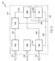
- FIG. 2 depicts further details of an embodiment of the compact FPGA-based digital motor controller 102.
- the compact FPGA-based digital motor controller 102 includes hardware circuitry for a communication interface 202, data registers 204, sensor interface 206, time inverter 208, commutation control 210, and linear digital compensation filter 212.
- the communication interface 202, data registers 204, sensor interface 206, time inverter 208, commutation control 210, and linear digital compensation filter 212 can be implemented in a single compact FPGA device or distributed between multiple compact FPGA devices.
- the communication interface 202, data registers 204, sensor interface 206, time inverter 208, and commutation control 210 are grouped in a first compact FPGA 214, while the linear digital compensation filter 212 is included in a second compact FPGA 216.
- This configuration may enable a common implementation of the first compact FPGA 214 and customized implementations of multiple instances of the second compact FPGA 216 to support multiple configurations of the DC brushless motor 108 and the rotary actuator 118 of FIG. 1 as part of a larger control system.
- Both the first compact FPGA 214 and the second compact FPGA 216 can be implemented using antifuse (one-time programmable) technology to decrease susceptibility to radiation, such as alpha particles, which can cause circuits to malfunction.
- antifuse one-time programmable
- the physical area of the first compact FPGA 214 and the second compact FPGA 216 may be about 1 inch-square (2.54 centimeters-square), where the first compact FPGA 214 and the second compact FPGA 216 contain about 100,000 gates each. It will be understood that the physical dimensions and number of gates for the first compact FPGA 214 and the second compact FPGA 216 can vary within the scope of the invention.
- the communication interface 202 is coupled to the communication link 124 to provide bidirectional communication with the system controller 122 of FIG. 1 .
- the communication interface 202 may support a variety of communication protocols and standards known in the art, such as RS-485 to support point-to-point and multi-drop bus communication.
- Data path 218 provides a bidirectional communication link between the communication interface 202 and the data registers 204.
- the communication interface 202 can perform communication protocol conversion, enabling the system controller 122 of FIG. 1 to read and write values in the data registers 204.
- the data registers 204 may store a variety of configuration parameters, commands, and status information.
- the data registers 204 can interface with the time inverter 208 and linear digital compensation filter 212 via data path 220 and data path 222 respectively.
- the sensor interface 206 receives sensor data from the sensor data link 106 and can provide conditioned sensor data to the commutation control 210 using data path 224.
- the sensor data received at the sensor interface 206 from the one or more sensors 104 of FIG. 1 may be formatted as digital position data.
- each of the one or more sensors 104 can generate a pulse as a rotor of the DC brushless motor 108 of FIG. 1 rotates in close physical proximity to a given sensor of the one or more sensors 104.
- the sensor interface 206 can use edge detection logic to trigger one or more timers to start, stop, and/or capture time values as transitional edges are detected. Timers may be included in the sensor interface 206 and/or in the commutation control 210.
- Speed data passed to the data registers 204 can be read by the system controller 122 of FIG. 1 using the communication interface 202.
- Speed data passed to the linear digital compensation filter 212 supplies a linear feedback control parameter to determine an error value for controlling the DC brushless motor 108 of FIG. 1 .
- the linear digital compensation filter 212 provides compensation logic for stable control of the DC brushless motor 108 of FIG. 1 .
- the linear digital compensation filter 212 may include one or more digital filter stages, such as an infinite impulse response (IIR) filter or a finite impulse response (FIR) filter.
- the linear digital compensation filter 212 may also include control loop logic for implementing any combination of proportional, integral, and/or differential control.
- a commanded speed value can be received from the data registers 204, in addition to one or more gain values and filter coefficients.
- the values from the time inverter 208 provide control loop feedback for linear digital control. This avoids complexity that may be associated with more advanced control loop designs, such as non-linear state space control.
- the commutation control 210 converts compensation commands from the linear digital compensation filter 212 into switching commands to output on the switch command link 116.
- the commutation control 210 may issue commands as PWM cycles with an adjustable duty cycle and/or frequency.
- the commutation control 210 implements predictive control to avoid noise induced errors.
- the predictive control can include filtering self-generated noise.
- the commutation control 210 may use conditioned sensor data generated by the sensor interface 206 to determine when an error condition likely exists. For example, the commutation control 210 can determine that the rate of change between position data is too fast, indicating that false pulses may be present.
- the commutation control 210 can maintain a switching sequence from a previous switching cycle or issue no switching commands until the error condition is removed.
- data paths 220-232 may be combined into any combination of shared data path. Sharing data paths can reduce the amount of resources dedicated to routing data paths within the compact FPGA-based digital motor controller 102.
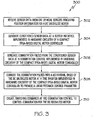
- FIG. 3 depicts a process 300 for providing a compact FPGA-based digital motor controller, such as the compact FPGA-based digital motor controller 102 of FIGs. 1 and 2 .
- the sensor interface 206 receives sensor data from one or more sensors 104 indicating position information for DC brushless motor 108.
- the sensor interface 206 generates conditioned sensor data.
- commutation control 210 generates commutation pulses from the conditioned sensor data.
- time inverter 208 converts the commutation pulses into a rotational speed of the DC brushless motor 108 to provide a linear feedback control parameter.
- commutation control 210 creates switching commands to control commutation for the DC brushless motor 108.
- Data registers 204 can be used to store command and status information, with communication interface 202 providing communication between the data registers 204 and system controller 122 of FIG. 1 .
- Linear digital compensation filter 212 may receive the rotational speed from the time inverter 208 and a speed command from the data registers 204, outputting a compensation command to the commutation control 210 responsive to the rotational speed and the speed command.
- the commutation control 210 can include additional functionality, such as performing predictive control to filter self-generated noise.
Landscapes
- Engineering & Computer Science (AREA)
- Power Engineering (AREA)
- Control Of Motors That Do Not Use Commutators (AREA)
Claims (15)
- Digitale Motorsteuereinheit (102) auf Grundlage eines kompakten feldprogrammierbaren Gate-Arrays (FPGA), umfassend:eine Sensorschnittstelle (206), die in Hardwareschaltungen implementiert ist, die dazu konfiguriert sind, Sensordaten von einem oder mehreren Sensoren (104) zu empfangen, die Positionsinformationen für einen bürstenlosen Gleichstrom(DC)-Motor (108) bereitstellen, und aufbereitete Sensordaten zu generieren;ein Kommunikationssteuerelement (210), das in Hardwareschaltungen implementiert ist, die dazu konfiguriert sind, Schaltbefehle zum Steuern von Kommutation für den bürstenlosen DC-Motor (108) zu erzeugen, wobei das Kommunikationssteuerelement (210) Kommutationsimpulse aus den aufbereiteten Sensordaten der Sensorschnittstelle (206) generiert, die als Zeitwerte formatiert sind, die eine verstrichene Zeit zwischen einer gemeinsamen Position des bürstenlosen DC-Motors oder mehreren Positionen des bürstenlosen DC-Motors angibt; undeinen Zeitwandler (208), der in Hardwareschaltungen implementiert ist, die dazu konfiguriert sind, die Kommutationsimpulse von dem Kommunikationssteuerelement (210) zu empfangen und die Kommutationsimpulse in eine Drehzahl des bürstenlosen DC-Motors (108) umzuwandeln, indem eine mathematische Inversion der Zeitwerte durchgeführt wird, um einen linearen Rückkopplungssteuerparameter bereitzustellen.
- Digitale Motorsteuereinheit (102) auf Grundlage eines kompakten FPGA nach Anspruch 1, ferner umfassend:Datenregister (204), die zum Speichern von Befehls- und Statusinformationen konfiguriert sind; undeine Kommunikationsschnittstelle (202) in Kommunikation mit den Datenregistern (204), um Kommunikation mit einer Systemsteuereinheit (122) bereitzustellen.
- Digitale Motorsteuereinheit (102) auf Grundlage eines kompakten FPGA nach Anspruch 2, ferner umfassend:ein lineares digitales Kompensationsfilter (212), das dazu konfiguriert ist, die Drehzahl von dem Zeitwandler (208) und einen Drehzahlbefehl von den Datenregistern (204) zu empfangen, wobei das lineare digitale Kompensationsfilter (212) in Antwort auf die Drehzahl und den Drehzahlbefehl einen Kompensationsbefehl an das Kommunikationssteuerelement (210) ausgibt.
- Digitale Motorsteuereinheit (102) auf Grundlage eines kompakten FPGA nach Anspruch 3, wobei der Zeitwandler (208) in einem ersten kompakten FPGA (214) implementiert ist und das lineare digitale Kompensationsfilter (212) in einem zweiten kompakten FPGA (216) implementiert ist.
- Digitale Motorsteuereinheit (102) auf Grundlage eines kompakten FPGA nach Anspruch 1, 2, 3 oder 4, wobei die Genauigkeit des Zeitwandlers (208) skalierbar ist.
- Digitale Motorsteuereinheit (102) auf Grundlage eines kompakten FPGA nach einem der vorangehenden Ansprüche, wobei das Kommunikationssteuerelement (210) eine prädiktive Steuerung zum Filtern von selbstgenerierten Rauschen durchführt.
- Digitale Motorsteuereinheit (102) auf Grundlage eines kompakten FPGA nach einem der vorangehenden Ansprüche, wobei die digitale Motorsteuereinheit (102) auf Grundlage eines kompakten FPGA in Antifuse-Technologie implementiert ist.
- Verfahren (300) zum Bereitstellen einer digitalen Motorsteuereinheit (102) auf Grundlage eines kompakten feldprogrammierbaren Gate-Arrays (FPGA), umfassend:Empfangen (302) von Sensordaten von einem oder mehreren Sensoren (104), die Positionsinformation für einen bürstenlosen Gleichstrom(DC)-Motor (108) angeben;Generieren (304) aufbereiteter Sensordaten an einer in Hardwareschaltungen implementieren Sensorschnittstelle (206) der digitalen Motorsteuereinheit (102) auf Grundlage eines kompakten FPGA;Generieren (306) von Kommutationsimpulsen aus den aufbereiteten Sensordaten an einer in Hardwareschaltungen implementieren Kommunikationssteuerelement (210) der digitalen Motorsteuereinheit (102) auf Grundlage eines kompakten FPGA, wobei die Kommutationsimpulse als Zeitwerte formatiert sind, die eine verstrichene Zeit zwischen einer gemeinsamen Position des bürstenlosen DC-Motors oder mehreren Positionen des bürstenlosen DC-Motors angeben;Umwandeln (308) der Kommutationsimpulse in eine Drehzahl des bürstenlosen DC-Motors (108) durch Durchführen einer mathematischen Inversion der Zeitwerte an einem in Hardwareschaltungen implementieren Zeitwandler (208) der digitalen Motorsteuereinheit (102) auf Grundlage eines kompakten FPGA, um einen linearen Rückkopplungssteuerparameter bereitzustellen; undErzeugen (310) von Schaltbefehlen am Kommunikationssteuerelement (210), um die Kommutation für den bürstenlosen DC-Motor (108) zu steuern.
- Verfahren nach Anspruch 8, ferner umfassend:Speichern von Befehls- und Statusinformationen in Datenregistern (204) der digitalen Motorsteuereinheit (102) auf Grundlage eines kompakten FPGA; undBereitstellen von Kommunikation zwischen den Datenregistern (204) und einer Systemsteuereinheit (122) über eine Kommunikationsschnittstelle (202) der digitalen Motorsteuereinheit (102) auf Grundlage des kompakten FPGA.
- Verfahren nach Anspruch 9, ferner umfassend:Empfangen der Drehzahl von dem Zeitwandler (208) und eines Drehzahlbefehls von den Datenregistern (204) an einem linearen digitalen Kompensationsfilter (212) der digitalen Motorsteuereinheit (102) auf Grundlage des kompakten FPGA; undAusgeben eines Kompensationsbefehls an das Kommunikationssteuerelement (210) in Antwort auf die Drehzahl und den Drehzahlbefehl.
- Verfahren nach Anspruch 10, wobei der Zeitwandler (208) in einem ersten kompakten FPGA (214) implementiert ist und das lineare digitale Kompensationsfilter (212) in einem zweiten kompakten FPGA (216) implementiert ist.
- Verfahren nach Anspruch 8, 9, 10 oder 11, wobei die Genauigkeit des Zeitwandlers (208) skalierbar ist.
- Verfahren nach einem der Ansprüche 8 bis 12, wobei das Kommunikationssteuerelement (210) eine prädiktive Steuerung zum Filtern von selbstgenerierten Rauschen durchführt.
- Verfahren nach einem der Ansprüche 8 bis 13, wobei die digitale Motorsteuereinheit (102) auf Grundlage eines kompakten FPGA in Antifuse-Technologie implementiert ist.
- Konstruktionsstruktur für eine digitale Motorsteuereinheit (102) auf Grundlage eines kompakten feldprogrammierbaren Gate-Arrays (FPGA), die greifbar in einem maschinenlesbaren Medium verkörpert ist, wobei die Konstruktionsstruktur die funktionelle Struktur zum Programmieren von einer oder mehreren FPGA-Vorrichtungen bereitstellt, um die digitale Motorsteuereinheit auf Grundlage des kompakten feldprogrammierbaren Gate-Arrays (FPGA) nach einem der Ansprüche 1 bis 6 zu implementieren.
Applications Claiming Priority (1)
| Application Number | Priority Date | Filing Date | Title |
|---|---|---|---|
| US12/501,660 US8294396B2 (en) | 2009-07-13 | 2009-07-13 | Compact FPGA-based digital motor controller |
Publications (2)
| Publication Number | Publication Date |
|---|---|
| EP2276166A1 EP2276166A1 (de) | 2011-01-19 |
| EP2276166B1 true EP2276166B1 (de) | 2018-04-18 |
Family
ID=42670417
Family Applications (1)
| Application Number | Title | Priority Date | Filing Date |
|---|---|---|---|
| EP10251247.2A Active EP2276166B1 (de) | 2009-07-13 | 2010-07-13 | Kompaktes FPGA-basiertes digitales Motorsteuergerät |
Country Status (3)
| Country | Link |
|---|---|
| US (2) | US8294396B2 (de) |
| EP (1) | EP2276166B1 (de) |
| JP (1) | JP2011024409A (de) |
Families Citing this family (33)
| Publication number | Priority date | Publication date | Assignee | Title |
|---|---|---|---|---|
| US8779705B2 (en) | 2011-02-25 | 2014-07-15 | Deere & Company | Synchronization of position and current measurements in an electric motor control application using an FPGA |
| CN102355178B (zh) * | 2011-09-05 | 2013-08-21 | 武汉科技大学 | 一种基于fpga的同步电动机励磁系统 |
| JP5999403B2 (ja) * | 2011-11-24 | 2016-09-28 | 富士電機株式会社 | 電動機の駆動装置 |
| US9781664B2 (en) | 2012-12-31 | 2017-10-03 | Elwha Llc | Cost-effective mobile connectivity protocols |
| US9832628B2 (en) | 2012-12-31 | 2017-11-28 | Elwha, Llc | Cost-effective mobile connectivity protocols |
| US9876762B2 (en) | 2012-12-31 | 2018-01-23 | Elwha Llc | Cost-effective mobile connectivity protocols |
| US9980114B2 (en) | 2013-03-15 | 2018-05-22 | Elwha Llc | Systems and methods for communication management |
| US8965288B2 (en) | 2012-12-31 | 2015-02-24 | Elwha Llc | Cost-effective mobile connectivity protocols |
| US9713013B2 (en) | 2013-03-15 | 2017-07-18 | Elwha Llc | Protocols for providing wireless communications connectivity maps |
| US9635605B2 (en) | 2013-03-15 | 2017-04-25 | Elwha Llc | Protocols for facilitating broader access in wireless communications |
| US9451394B2 (en) | 2012-12-31 | 2016-09-20 | Elwha Llc | Cost-effective mobile connectivity protocols |
| US9444376B2 (en) | 2013-02-22 | 2016-09-13 | Hamilton Sundstrand Corporation | Variable link sensorless brushless direct current motor controller for space and hardened applications |
| US9843917B2 (en) | 2013-03-15 | 2017-12-12 | Elwha, Llc | Protocols for facilitating charge-authorized connectivity in wireless communications |
| US9596584B2 (en) | 2013-03-15 | 2017-03-14 | Elwha Llc | Protocols for facilitating broader access in wireless communications by conditionally authorizing a charge to an account of a third party |
| US9866706B2 (en) | 2013-03-15 | 2018-01-09 | Elwha Llc | Protocols for facilitating broader access in wireless communications |
| US9813887B2 (en) | 2013-03-15 | 2017-11-07 | Elwha Llc | Protocols for facilitating broader access in wireless communications responsive to charge authorization statuses |
| US9706060B2 (en) | 2013-03-15 | 2017-07-11 | Elwha Llc | Protocols for facilitating broader access in wireless communications |
| US9781554B2 (en) | 2013-03-15 | 2017-10-03 | Elwha Llc | Protocols for facilitating third party authorization for a rooted communication device in wireless communications |
| US9693214B2 (en) | 2013-03-15 | 2017-06-27 | Elwha Llc | Protocols for facilitating broader access in wireless communications |
| US9706382B2 (en) | 2013-03-15 | 2017-07-11 | Elwha Llc | Protocols for allocating communication services cost in wireless communications |
| US9807582B2 (en) | 2013-03-15 | 2017-10-31 | Elwha Llc | Protocols for facilitating broader access in wireless communications |
| US9059732B2 (en) | 2013-03-21 | 2015-06-16 | Hamilton Sundstrand Corporation | Resolver-to-digital converter |
| JP2015171241A (ja) * | 2014-03-07 | 2015-09-28 | ハミルトン・サンドストランド・コーポレイションHamilton Sundstrand Corporation | モータ制御器システムおよびモータを制御するための方法 |
| US9742326B2 (en) * | 2014-07-22 | 2017-08-22 | Hamilton Sundstrand Space Systems International, Inc. | Field programmable gate array based brushless DC motor speed detector |
| WO2016134319A1 (en) | 2015-02-19 | 2016-08-25 | Enphase Energy, Inc. | Method and apparatus for time-domain droop control with integrated phasor current control |
| CN104749997A (zh) * | 2015-03-16 | 2015-07-01 | 中国科学院光电研究院 | 用于激光跟踪仪精密伺服系统的驱动控制电路 |
| US9601003B2 (en) | 2015-08-17 | 2017-03-21 | Hamilton Sundstrand Space Systems International, Inc. | Sensor and control systems for electrical machines |
| CN105429524A (zh) * | 2015-12-15 | 2016-03-23 | 李哲 | 基于fpga的无刷直流电机调速系统 |
| US10289092B2 (en) * | 2016-01-14 | 2019-05-14 | Hamilton Sundstrand Space Systems International Inc. | Digital motor controller stability analysis tool |
| US20180259091A1 (en) * | 2017-03-10 | 2018-09-13 | Hamilton Sundstrand Corporation | Control valve positioning system |
| US11199585B2 (en) | 2019-03-26 | 2021-12-14 | Hamilton Sundstrand Corporation | Highspeed data interface for distributed system motor controllers |
| US20250007442A1 (en) * | 2021-10-28 | 2025-01-02 | Atieva, Inc. | Fault condition handling in an electric vehicle powertrain |
| CN116055535A (zh) * | 2022-12-14 | 2023-05-02 | 中国工程物理研究院应用电子学研究所 | 一种嵌入式实时控制装置、控制系统及控制方法 |
Family Cites Families (35)
| Publication number | Priority date | Publication date | Assignee | Title |
|---|---|---|---|---|
| US4254369A (en) * | 1978-11-13 | 1981-03-03 | The Singer Company | High accuracy shaft angle linear DC voltage conversion using low accuracy devices |
| US4513378A (en) * | 1981-10-20 | 1985-04-23 | Antkowiak Edward T | High-accuracy navigating apparatus with step-driven projected chart |
| US4751438A (en) | 1985-12-18 | 1988-06-14 | Sundstrand Corporation | Brushless DC motor control |
| JPS62277085A (ja) * | 1986-05-24 | 1987-12-01 | Ricoh Res Inst Of Gen Electron | 直流サ−ボモ−タ制御方式 |
| JPH0375567A (ja) | 1989-08-17 | 1991-03-29 | Toshiba Corp | 速度検出方式 |
| US5350988A (en) | 1990-07-10 | 1994-09-27 | Alliedsignal, Inc. | Digital motor controller |
| EP0515043A3 (en) | 1991-05-24 | 1993-11-18 | Actel Corp | Direct interconnect for functional circuit module array |
| DE69331061T2 (de) * | 1992-08-10 | 2002-06-06 | Monolithic System Tech Inc | Fehlertolerantes hierarchisiertes Bussystem |
| US5349248A (en) * | 1992-09-03 | 1994-09-20 | Xilinx, Inc. | Adaptive programming method for antifuse technology |
| US5426614A (en) * | 1994-01-13 | 1995-06-20 | Texas Instruments Incorporated | Memory cell with programmable antifuse technology |
| US5998783A (en) * | 1994-06-01 | 1999-12-07 | Stridsberg Innovation Ab | Heat protected position transducer in an electric motor |
| US5537019A (en) | 1995-03-14 | 1996-07-16 | A. O. Smith Corporation | Switched reluctance motor providing rotor position detection at high speeds without a separate rotor shaft position sensor |
| US5999168A (en) * | 1995-09-27 | 1999-12-07 | Immersion Corporation | Haptic accelerator for force feedback computer peripherals |
| EP1063753B1 (de) | 1999-06-22 | 2009-07-22 | Levitronix LLC | Elektrischer Drehantrieb mit einem magnetisch gelagerten Rotor |
| US6891346B2 (en) | 2000-12-30 | 2005-05-10 | Hamilton Sundstrand Corporation | Commutation and velocity control system for a brushless DC motor |
| US7055038B2 (en) * | 2001-05-07 | 2006-05-30 | Ati International Srl | Method and apparatus for maintaining secure and nonsecure data in a shared memory system |
| JP4552353B2 (ja) * | 2001-05-11 | 2010-09-29 | ソニー株式会社 | サーボ・アクチュエータ並びにその位置検出装置 |
| US6808345B2 (en) * | 2001-10-16 | 2004-10-26 | Toshiba Kikai Kabushiki Kaisha | Tool, tool holder, and machine tool |
| WO2004004109A2 (en) * | 2002-07-01 | 2004-01-08 | Xidem, Inc. | Electronically controlled electric motor |
| US7362070B2 (en) | 2002-11-04 | 2008-04-22 | Hamilton Sundstrand Corporation | Electric motor control system including position determination and error correction |
| JP2004201487A (ja) | 2002-11-28 | 2004-07-15 | Nsk Ltd | モータ及びその駆動制御装置 |
| JP2004242389A (ja) | 2003-02-04 | 2004-08-26 | Daiwa Industries Ltd | センサレスdcブラシレスモータ |
| US7245103B2 (en) | 2003-03-03 | 2007-07-17 | Lexmark International, Inc. | Motor speed and position control |
| US7607437B2 (en) * | 2003-08-04 | 2009-10-27 | Cardinal Health 203, Inc. | Compressor control system and method for a portable ventilator |
| JP2005102377A (ja) | 2003-09-24 | 2005-04-14 | Gifu Univ | 多軸モータ制御システム |
| US7205738B2 (en) | 2004-03-24 | 2007-04-17 | Lexmark International, Inc. | Method and apparatus for time-based dc motor commutation |
| US7332884B2 (en) | 2004-07-16 | 2008-02-19 | Hamilton Sundstrand Corporation | Electric motor control strategies |
| JP3814826B2 (ja) * | 2004-12-10 | 2006-08-30 | 有限会社シー・アンド・エス国際研究所 | 同期電動機のベクトル制御方法 |
| US7245096B2 (en) | 2005-11-21 | 2007-07-17 | Comair Rotron, Inc. | Method and apparatus for controlling the speed of a DC motor |
| US7466088B2 (en) | 2005-12-16 | 2008-12-16 | Hamilton Sundstrand Corporation | Signal control for motor position determination |
| US7895560B2 (en) * | 2006-10-02 | 2011-02-22 | William Stuart Lovell | Continuous flow instant logic binary circuitry actively structured by code-generated pass transistor interconnects |
| US7489097B2 (en) * | 2006-11-02 | 2009-02-10 | Chrysler Llc | Sensorless position detection for a brushless direct current motor during inverter standby |
| CA2645774C (en) * | 2006-12-22 | 2010-01-12 | Sidense Corp. | A power up detection system for a memory device |
| US7835630B2 (en) | 2007-04-06 | 2010-11-16 | The Johns Hopkins University | Adaptive and reconfigurable system for DC motor control |
| US8290782B2 (en) * | 2008-07-24 | 2012-10-16 | Dts, Inc. | Compression of audio scale-factors by two-dimensional transformation |
-
2009
- 2009-07-13 US US12/501,660 patent/US8294396B2/en not_active Ceased
-
2010
- 2010-06-23 JP JP2010142133A patent/JP2011024409A/ja not_active Ceased
- 2010-07-13 EP EP10251247.2A patent/EP2276166B1/de active Active
-
2013
- 2013-07-16 US US13/943,193 patent/USRE45388E1/en active Active
Non-Patent Citations (1)
| Title |
|---|
| None * |
Also Published As
| Publication number | Publication date |
|---|---|
| USRE45388E1 (en) | 2015-02-24 |
| EP2276166A1 (de) | 2011-01-19 |
| US20110006713A1 (en) | 2011-01-13 |
| JP2011024409A (ja) | 2011-02-03 |
| US8294396B2 (en) | 2012-10-23 |
Similar Documents
| Publication | Publication Date | Title |
|---|---|---|
| EP2276166B1 (de) | Kompaktes FPGA-basiertes digitales Motorsteuergerät | |
| JP4987119B2 (ja) | ブラシレスモータ装置及び制御装置 | |
| CN107521553B (zh) | 具有两个控制器和闭环积分作用的电动助力转向 | |
| JP5917294B2 (ja) | モータ駆動回路 | |
| CN100409558C (zh) | 基于fpga的直流电机控制器 | |
| US20160056692A1 (en) | Motor control device | |
| JP5313454B2 (ja) | 電動車両の停止制御方法 | |
| JP5358367B2 (ja) | エンコーダーシステム | |
| EP2977727B1 (de) | Feldprogrammierbarer gate-array-basierter drehzahldetektor für bürstenlosen gleichstrommotor | |
| WO2022269950A1 (ja) | 電動機制御装置 | |
| JPWO2020149002A1 (ja) | モータ制御装置 | |
| CN111344943B (zh) | 控制器、具有该控制器的马达控制系统以及具有该马达控制系统的电动助力转向系统 | |
| JP2024120855A (ja) | ブラシレスdcモータの回転速度推定方法および制御装置 | |
| JP5493680B2 (ja) | モータ制御装置および電動パワーステアリング装置 | |
| CN101499756A (zh) | 控制一直流无刷马达的方法及控制电路 | |
| CN204392127U (zh) | 高电压大功率步进电机控制器 | |
| JP6831346B2 (ja) | モータ装置及びモータの駆動制御方法 | |
| JP4011839B2 (ja) | ブラシレスモータの制御装置 | |
| WO2012077767A1 (ja) | モータ制御回路 | |
| JP2021523665A (ja) | 外部部材の駆動または位置決め用メカトロニックアセンブリ | |
| TW201427267A (zh) | 模組化風扇馬達控制電路及其控制方法 | |
| JP3310555B2 (ja) | 位置決め制御装置 | |
| JPH10247109A (ja) | エンコーダの異常を検出する方法およびその装置、ならびにアクチュエータ用の制御装置 | |
| PAITHANE et al. | IMPLEMENTING JERK FREE BLDC POSITION CONTROL USING SOC WITH FOURTH ORDER TRAJECTORY PLANNING | |
| KR20250053501A (ko) | 손가락 의수 내장형 모터 구동 시스템 및 그 제어 방법 |
Legal Events
| Date | Code | Title | Description |
|---|---|---|---|
| PUAI | Public reference made under article 153(3) epc to a published international application that has entered the european phase |
Free format text: ORIGINAL CODE: 0009012 |
|
| AK | Designated contracting states |
Kind code of ref document: A1 Designated state(s): AL AT BE BG CH CY CZ DE DK EE ES FI FR GB GR HR HU IE IS IT LI LT LU LV MC MK MT NL NO PL PT RO SE SI SK SM TR |
|
| AX | Request for extension of the european patent |
Extension state: BA ME RS |
|
| 17P | Request for examination filed |
Effective date: 20110719 |
|
| RAP1 | Party data changed (applicant data changed or rights of an application transferred) |
Owner name: HAMILTON SUNDSTRAND SPACE SYSTEMS INTERNATIONAL, I |
|
| 17Q | First examination report despatched |
Effective date: 20150415 |
|
| REG | Reference to a national code |
Ref country code: DE Ref legal event code: R079 Ref document number: 602010049981 Country of ref document: DE Free format text: PREVIOUS MAIN CLASS: H02P0006000000 Ipc: H02P0006170000 |
|
| GRAP | Despatch of communication of intention to grant a patent |
Free format text: ORIGINAL CODE: EPIDOSNIGR1 |
|
| STAA | Information on the status of an ep patent application or granted ep patent |
Free format text: STATUS: GRANT OF PATENT IS INTENDED |
|
| RIC1 | Information provided on ipc code assigned before grant |
Ipc: H02P 6/17 20160101AFI20171009BHEP Ipc: H02P 6/34 20160101ALI20171009BHEP |
|
| INTG | Intention to grant announced |
Effective date: 20171031 |
|
| GRAS | Grant fee paid |
Free format text: ORIGINAL CODE: EPIDOSNIGR3 |
|
| GRAA | (expected) grant |
Free format text: ORIGINAL CODE: 0009210 |
|
| STAA | Information on the status of an ep patent application or granted ep patent |
Free format text: STATUS: THE PATENT HAS BEEN GRANTED |
|
| AK | Designated contracting states |
Kind code of ref document: B1 Designated state(s): AL AT BE BG CH CY CZ DE DK EE ES FI FR GB GR HR HU IE IS IT LI LT LU LV MC MK MT NL NO PL PT RO SE SI SK SM TR |
|
| REG | Reference to a national code |
Ref country code: GB Ref legal event code: FG4D |
|
| REG | Reference to a national code |
Ref country code: CH Ref legal event code: EP |
|
| REG | Reference to a national code |
Ref country code: AT Ref legal event code: REF Ref document number: 991483 Country of ref document: AT Kind code of ref document: T Effective date: 20180515 |
|
| REG | Reference to a national code |
Ref country code: IE Ref legal event code: FG4D |
|
| REG | Reference to a national code |
Ref country code: DE Ref legal event code: R096 Ref document number: 602010049981 Country of ref document: DE |
|
| REG | Reference to a national code |
Ref country code: FR Ref legal event code: PLFP Year of fee payment: 9 |
|
| REG | Reference to a national code |
Ref country code: NL Ref legal event code: MP Effective date: 20180418 |
|
| REG | Reference to a national code |
Ref country code: LT Ref legal event code: MG4D |
|
| PG25 | Lapsed in a contracting state [announced via postgrant information from national office to epo] |
Ref country code: NL Free format text: LAPSE BECAUSE OF FAILURE TO SUBMIT A TRANSLATION OF THE DESCRIPTION OR TO PAY THE FEE WITHIN THE PRESCRIBED TIME-LIMIT Effective date: 20180418 |
|
| PG25 | Lapsed in a contracting state [announced via postgrant information from national office to epo] |
Ref country code: ES Free format text: LAPSE BECAUSE OF FAILURE TO SUBMIT A TRANSLATION OF THE DESCRIPTION OR TO PAY THE FEE WITHIN THE PRESCRIBED TIME-LIMIT Effective date: 20180418 Ref country code: AL Free format text: LAPSE BECAUSE OF FAILURE TO SUBMIT A TRANSLATION OF THE DESCRIPTION OR TO PAY THE FEE WITHIN THE PRESCRIBED TIME-LIMIT Effective date: 20180418 Ref country code: PL Free format text: LAPSE BECAUSE OF FAILURE TO SUBMIT A TRANSLATION OF THE DESCRIPTION OR TO PAY THE FEE WITHIN THE PRESCRIBED TIME-LIMIT Effective date: 20180418 Ref country code: SE Free format text: LAPSE BECAUSE OF FAILURE TO SUBMIT A TRANSLATION OF THE DESCRIPTION OR TO PAY THE FEE WITHIN THE PRESCRIBED TIME-LIMIT Effective date: 20180418 Ref country code: NO Free format text: LAPSE BECAUSE OF FAILURE TO SUBMIT A TRANSLATION OF THE DESCRIPTION OR TO PAY THE FEE WITHIN THE PRESCRIBED TIME-LIMIT Effective date: 20180718 Ref country code: FI Free format text: LAPSE BECAUSE OF FAILURE TO SUBMIT A TRANSLATION OF THE DESCRIPTION OR TO PAY THE FEE WITHIN THE PRESCRIBED TIME-LIMIT Effective date: 20180418 Ref country code: LT Free format text: LAPSE BECAUSE OF FAILURE TO SUBMIT A TRANSLATION OF THE DESCRIPTION OR TO PAY THE FEE WITHIN THE PRESCRIBED TIME-LIMIT Effective date: 20180418 Ref country code: BG Free format text: LAPSE BECAUSE OF FAILURE TO SUBMIT A TRANSLATION OF THE DESCRIPTION OR TO PAY THE FEE WITHIN THE PRESCRIBED TIME-LIMIT Effective date: 20180718 |
|
| PG25 | Lapsed in a contracting state [announced via postgrant information from national office to epo] |
Ref country code: HR Free format text: LAPSE BECAUSE OF FAILURE TO SUBMIT A TRANSLATION OF THE DESCRIPTION OR TO PAY THE FEE WITHIN THE PRESCRIBED TIME-LIMIT Effective date: 20180418 Ref country code: GR Free format text: LAPSE BECAUSE OF FAILURE TO SUBMIT A TRANSLATION OF THE DESCRIPTION OR TO PAY THE FEE WITHIN THE PRESCRIBED TIME-LIMIT Effective date: 20180719 Ref country code: LV Free format text: LAPSE BECAUSE OF FAILURE TO SUBMIT A TRANSLATION OF THE DESCRIPTION OR TO PAY THE FEE WITHIN THE PRESCRIBED TIME-LIMIT Effective date: 20180418 |
|
| REG | Reference to a national code |
Ref country code: AT Ref legal event code: MK05 Ref document number: 991483 Country of ref document: AT Kind code of ref document: T Effective date: 20180418 |
|
| PG25 | Lapsed in a contracting state [announced via postgrant information from national office to epo] |
Ref country code: PT Free format text: LAPSE BECAUSE OF FAILURE TO SUBMIT A TRANSLATION OF THE DESCRIPTION OR TO PAY THE FEE WITHIN THE PRESCRIBED TIME-LIMIT Effective date: 20180820 |
|
| REG | Reference to a national code |
Ref country code: DE Ref legal event code: R097 Ref document number: 602010049981 Country of ref document: DE |
|
| PG25 | Lapsed in a contracting state [announced via postgrant information from national office to epo] |
Ref country code: CZ Free format text: LAPSE BECAUSE OF FAILURE TO SUBMIT A TRANSLATION OF THE DESCRIPTION OR TO PAY THE FEE WITHIN THE PRESCRIBED TIME-LIMIT Effective date: 20180418 Ref country code: SK Free format text: LAPSE BECAUSE OF FAILURE TO SUBMIT A TRANSLATION OF THE DESCRIPTION OR TO PAY THE FEE WITHIN THE PRESCRIBED TIME-LIMIT Effective date: 20180418 Ref country code: RO Free format text: LAPSE BECAUSE OF FAILURE TO SUBMIT A TRANSLATION OF THE DESCRIPTION OR TO PAY THE FEE WITHIN THE PRESCRIBED TIME-LIMIT Effective date: 20180418 Ref country code: AT Free format text: LAPSE BECAUSE OF FAILURE TO SUBMIT A TRANSLATION OF THE DESCRIPTION OR TO PAY THE FEE WITHIN THE PRESCRIBED TIME-LIMIT Effective date: 20180418 Ref country code: DK Free format text: LAPSE BECAUSE OF FAILURE TO SUBMIT A TRANSLATION OF THE DESCRIPTION OR TO PAY THE FEE WITHIN THE PRESCRIBED TIME-LIMIT Effective date: 20180418 Ref country code: EE Free format text: LAPSE BECAUSE OF FAILURE TO SUBMIT A TRANSLATION OF THE DESCRIPTION OR TO PAY THE FEE WITHIN THE PRESCRIBED TIME-LIMIT Effective date: 20180418 |
|
| PLBE | No opposition filed within time limit |
Free format text: ORIGINAL CODE: 0009261 |
|
| STAA | Information on the status of an ep patent application or granted ep patent |
Free format text: STATUS: NO OPPOSITION FILED WITHIN TIME LIMIT |
|
| PG25 | Lapsed in a contracting state [announced via postgrant information from national office to epo] |
Ref country code: IT Free format text: LAPSE BECAUSE OF FAILURE TO SUBMIT A TRANSLATION OF THE DESCRIPTION OR TO PAY THE FEE WITHIN THE PRESCRIBED TIME-LIMIT Effective date: 20180418 Ref country code: SM Free format text: LAPSE BECAUSE OF FAILURE TO SUBMIT A TRANSLATION OF THE DESCRIPTION OR TO PAY THE FEE WITHIN THE PRESCRIBED TIME-LIMIT Effective date: 20180418 |
|
| REG | Reference to a national code |
Ref country code: CH Ref legal event code: PL |
|
| 26N | No opposition filed |
Effective date: 20190121 |
|
| PG25 | Lapsed in a contracting state [announced via postgrant information from national office to epo] |
Ref country code: MC Free format text: LAPSE BECAUSE OF FAILURE TO SUBMIT A TRANSLATION OF THE DESCRIPTION OR TO PAY THE FEE WITHIN THE PRESCRIBED TIME-LIMIT Effective date: 20180418 Ref country code: LU Free format text: LAPSE BECAUSE OF NON-PAYMENT OF DUE FEES Effective date: 20180713 |
|
| REG | Reference to a national code |
Ref country code: BE Ref legal event code: MM Effective date: 20180731 |
|
| REG | Reference to a national code |
Ref country code: IE Ref legal event code: MM4A |
|
| PG25 | Lapsed in a contracting state [announced via postgrant information from national office to epo] |
Ref country code: LI Free format text: LAPSE BECAUSE OF NON-PAYMENT OF DUE FEES Effective date: 20180731 Ref country code: CH Free format text: LAPSE BECAUSE OF NON-PAYMENT OF DUE FEES Effective date: 20180731 Ref country code: IE Free format text: LAPSE BECAUSE OF NON-PAYMENT OF DUE FEES Effective date: 20180713 |
|
| PG25 | Lapsed in a contracting state [announced via postgrant information from national office to epo] |
Ref country code: BE Free format text: LAPSE BECAUSE OF NON-PAYMENT OF DUE FEES Effective date: 20180731 Ref country code: SI Free format text: LAPSE BECAUSE OF FAILURE TO SUBMIT A TRANSLATION OF THE DESCRIPTION OR TO PAY THE FEE WITHIN THE PRESCRIBED TIME-LIMIT Effective date: 20180418 |
|
| PG25 | Lapsed in a contracting state [announced via postgrant information from national office to epo] |
Ref country code: MT Free format text: LAPSE BECAUSE OF NON-PAYMENT OF DUE FEES Effective date: 20180713 |
|
| PG25 | Lapsed in a contracting state [announced via postgrant information from national office to epo] |
Ref country code: TR Free format text: LAPSE BECAUSE OF FAILURE TO SUBMIT A TRANSLATION OF THE DESCRIPTION OR TO PAY THE FEE WITHIN THE PRESCRIBED TIME-LIMIT Effective date: 20180418 |
|
| PG25 | Lapsed in a contracting state [announced via postgrant information from national office to epo] |
Ref country code: HU Free format text: LAPSE BECAUSE OF FAILURE TO SUBMIT A TRANSLATION OF THE DESCRIPTION OR TO PAY THE FEE WITHIN THE PRESCRIBED TIME-LIMIT; INVALID AB INITIO Effective date: 20100713 |
|
| PG25 | Lapsed in a contracting state [announced via postgrant information from national office to epo] |
Ref country code: MK Free format text: LAPSE BECAUSE OF NON-PAYMENT OF DUE FEES Effective date: 20180418 Ref country code: CY Free format text: LAPSE BECAUSE OF FAILURE TO SUBMIT A TRANSLATION OF THE DESCRIPTION OR TO PAY THE FEE WITHIN THE PRESCRIBED TIME-LIMIT Effective date: 20180418 |
|
| PG25 | Lapsed in a contracting state [announced via postgrant information from national office to epo] |
Ref country code: IS Free format text: LAPSE BECAUSE OF FAILURE TO SUBMIT A TRANSLATION OF THE DESCRIPTION OR TO PAY THE FEE WITHIN THE PRESCRIBED TIME-LIMIT Effective date: 20180818 |
|
| PGFP | Annual fee paid to national office [announced via postgrant information from national office to epo] |
Ref country code: GB Payment date: 20250619 Year of fee payment: 16 |
|
| PGFP | Annual fee paid to national office [announced via postgrant information from national office to epo] |
Ref country code: FR Payment date: 20250620 Year of fee payment: 16 |
|
| PGFP | Annual fee paid to national office [announced via postgrant information from national office to epo] |
Ref country code: DE Payment date: 20250620 Year of fee payment: 16 |
|
| P01 | Opt-out of the competence of the unified patent court (upc) registered |
Free format text: CASE NUMBER: UPC_APP_0016464_2276166/2025 Effective date: 20251209 |