EP2274653B1 - A three dimensional holographic volumetric display - Google Patents
A three dimensional holographic volumetric display Download PDFInfo
- Publication number
- EP2274653B1 EP2274653B1 EP09716381.0A EP09716381A EP2274653B1 EP 2274653 B1 EP2274653 B1 EP 2274653B1 EP 09716381 A EP09716381 A EP 09716381A EP 2274653 B1 EP2274653 B1 EP 2274653B1
- Authority
- EP
- European Patent Office
- Prior art keywords
- holographic
- sub
- screen
- holograms
- display
- Prior art date
- Legal status (The legal status is an assumption and is not a legal conclusion. Google has not performed a legal analysis and makes no representation as to the accuracy of the status listed.)
- Active
Links
- 238000000034 method Methods 0.000 claims description 28
- 230000015654 memory Effects 0.000 claims description 19
- 239000011159 matrix material Substances 0.000 claims description 12
- 238000004519 manufacturing process Methods 0.000 claims description 11
- VYPSYNLAJGMNEJ-UHFFFAOYSA-N Silicium dioxide Chemical compound O=[Si]=O VYPSYNLAJGMNEJ-UHFFFAOYSA-N 0.000 claims description 8
- 230000005540 biological transmission Effects 0.000 claims description 8
- 239000000463 material Substances 0.000 claims description 7
- 238000001093 holography Methods 0.000 claims description 6
- 239000002131 composite material Substances 0.000 claims description 5
- 239000000377 silicon dioxide Substances 0.000 claims description 4
- 238000012546 transfer Methods 0.000 claims description 4
- 238000004049 embossing Methods 0.000 claims description 3
- 238000007540 photo-reduction reaction Methods 0.000 claims description 3
- 229920000642 polymer Polymers 0.000 claims description 3
- 230000001131 transforming effect Effects 0.000 claims description 3
- 238000000206 photolithography Methods 0.000 claims description 2
- 238000005516 engineering process Methods 0.000 description 16
- 239000003086 colorant Substances 0.000 description 15
- 238000005286 illumination Methods 0.000 description 15
- 239000010408 film Substances 0.000 description 13
- 239000004973 liquid crystal related substance Substances 0.000 description 9
- 238000013459 approach Methods 0.000 description 7
- 238000012545 processing Methods 0.000 description 7
- 230000033001 locomotion Effects 0.000 description 4
- 239000004065 semiconductor Substances 0.000 description 4
- 230000003068 static effect Effects 0.000 description 4
- 239000000758 substrate Substances 0.000 description 4
- 238000003491 array Methods 0.000 description 3
- 238000003384 imaging method Methods 0.000 description 3
- 229910001507 metal halide Inorganic materials 0.000 description 3
- 150000005309 metal halides Chemical class 0.000 description 3
- 230000002688 persistence Effects 0.000 description 3
- 230000008569 process Effects 0.000 description 3
- 238000012163 sequencing technique Methods 0.000 description 3
- 239000008186 active pharmaceutical agent Substances 0.000 description 2
- 230000001427 coherent effect Effects 0.000 description 2
- 238000012937 correction Methods 0.000 description 2
- 238000007667 floating Methods 0.000 description 2
- 239000011521 glass Substances 0.000 description 2
- 229910052736 halogen Inorganic materials 0.000 description 2
- 150000002367 halogens Chemical class 0.000 description 2
- 238000013507 mapping Methods 0.000 description 2
- 230000003287 optical effect Effects 0.000 description 2
- 238000007639 printing Methods 0.000 description 2
- 238000009987 spinning Methods 0.000 description 2
- 238000012800 visualization Methods 0.000 description 2
- 241000283070 Equus zebra Species 0.000 description 1
- 238000009825 accumulation Methods 0.000 description 1
- 230000003213 activating effect Effects 0.000 description 1
- 230000008901 benefit Effects 0.000 description 1
- 230000008859 change Effects 0.000 description 1
- 238000013329 compounding Methods 0.000 description 1
- 238000011960 computer-aided design Methods 0.000 description 1
- 239000000470 constituent Substances 0.000 description 1
- 238000010276 construction Methods 0.000 description 1
- 238000001816 cooling Methods 0.000 description 1
- 239000013078 crystal Substances 0.000 description 1
- 238000002059 diagnostic imaging Methods 0.000 description 1
- 239000000839 emulsion Substances 0.000 description 1
- 238000010297 mechanical methods and process Methods 0.000 description 1
- 238000012986 modification Methods 0.000 description 1
- 230000004048 modification Effects 0.000 description 1
- -1 plate Substances 0.000 description 1
- 230000009467 reduction Effects 0.000 description 1
- 238000006722 reduction reaction Methods 0.000 description 1
- 238000005070 sampling Methods 0.000 description 1
- 229910052710 silicon Inorganic materials 0.000 description 1
- 239000010703 silicon Substances 0.000 description 1
- 230000003595 spectral effect Effects 0.000 description 1
- 230000001360 synchronised effect Effects 0.000 description 1
- 239000010409 thin film Substances 0.000 description 1
- WFKWXMTUELFFGS-UHFFFAOYSA-N tungsten Chemical compound [W] WFKWXMTUELFFGS-UHFFFAOYSA-N 0.000 description 1
- 229910052721 tungsten Inorganic materials 0.000 description 1
- 239000010937 tungsten Substances 0.000 description 1
- 230000003936 working memory Effects 0.000 description 1
Images


Classifications
-
- G—PHYSICS
- G03—PHOTOGRAPHY; CINEMATOGRAPHY; ANALOGOUS TECHNIQUES USING WAVES OTHER THAN OPTICAL WAVES; ELECTROGRAPHY; HOLOGRAPHY
- G03H—HOLOGRAPHIC PROCESSES OR APPARATUS
- G03H1/00—Holographic processes or apparatus using light, infrared or ultraviolet waves for obtaining holograms or for obtaining an image from them; Details peculiar thereto
- G03H1/26—Processes or apparatus specially adapted to produce multiple sub- holograms or to obtain images from them, e.g. multicolour technique
- G03H1/30—Processes or apparatus specially adapted to produce multiple sub- holograms or to obtain images from them, e.g. multicolour technique discrete holograms only
-
- G—PHYSICS
- G03—PHOTOGRAPHY; CINEMATOGRAPHY; ANALOGOUS TECHNIQUES USING WAVES OTHER THAN OPTICAL WAVES; ELECTROGRAPHY; HOLOGRAPHY
- G03H—HOLOGRAPHIC PROCESSES OR APPARATUS
- G03H1/00—Holographic processes or apparatus using light, infrared or ultraviolet waves for obtaining holograms or for obtaining an image from them; Details peculiar thereto
- G03H1/22—Processes or apparatus for obtaining an optical image from holograms
- G03H1/2286—Particular reconstruction light ; Beam properties
-
- G—PHYSICS
- G03—PHOTOGRAPHY; CINEMATOGRAPHY; ANALOGOUS TECHNIQUES USING WAVES OTHER THAN OPTICAL WAVES; ELECTROGRAPHY; HOLOGRAPHY
- G03H—HOLOGRAPHIC PROCESSES OR APPARATUS
- G03H1/00—Holographic processes or apparatus using light, infrared or ultraviolet waves for obtaining holograms or for obtaining an image from them; Details peculiar thereto
- G03H1/04—Processes or apparatus for producing holograms
- G03H1/20—Copying holograms by holographic, i.e. optical means
-
- G—PHYSICS
- G03—PHOTOGRAPHY; CINEMATOGRAPHY; ANALOGOUS TECHNIQUES USING WAVES OTHER THAN OPTICAL WAVES; ELECTROGRAPHY; HOLOGRAPHY
- G03H—HOLOGRAPHIC PROCESSES OR APPARATUS
- G03H1/00—Holographic processes or apparatus using light, infrared or ultraviolet waves for obtaining holograms or for obtaining an image from them; Details peculiar thereto
- G03H1/22—Processes or apparatus for obtaining an optical image from holograms
- G03H1/2249—Holobject properties
-
- G—PHYSICS
- G03—PHOTOGRAPHY; CINEMATOGRAPHY; ANALOGOUS TECHNIQUES USING WAVES OTHER THAN OPTICAL WAVES; ELECTROGRAPHY; HOLOGRAPHY
- G03H—HOLOGRAPHIC PROCESSES OR APPARATUS
- G03H1/00—Holographic processes or apparatus using light, infrared or ultraviolet waves for obtaining holograms or for obtaining an image from them; Details peculiar thereto
- G03H1/04—Processes or apparatus for producing holograms
- G03H1/0402—Recording geometries or arrangements
- G03H2001/0415—Recording geometries or arrangements for recording reflection holograms
-
- G—PHYSICS
- G03—PHOTOGRAPHY; CINEMATOGRAPHY; ANALOGOUS TECHNIQUES USING WAVES OTHER THAN OPTICAL WAVES; ELECTROGRAPHY; HOLOGRAPHY
- G03H—HOLOGRAPHIC PROCESSES OR APPARATUS
- G03H1/00—Holographic processes or apparatus using light, infrared or ultraviolet waves for obtaining holograms or for obtaining an image from them; Details peculiar thereto
- G03H1/22—Processes or apparatus for obtaining an optical image from holograms
- G03H1/2249—Holobject properties
- G03H2001/2263—Multicoloured holobject
- G03H2001/2271—RGB holobject
-
- G—PHYSICS
- G03—PHOTOGRAPHY; CINEMATOGRAPHY; ANALOGOUS TECHNIQUES USING WAVES OTHER THAN OPTICAL WAVES; ELECTROGRAPHY; HOLOGRAPHY
- G03H—HOLOGRAPHIC PROCESSES OR APPARATUS
- G03H1/00—Holographic processes or apparatus using light, infrared or ultraviolet waves for obtaining holograms or for obtaining an image from them; Details peculiar thereto
- G03H1/22—Processes or apparatus for obtaining an optical image from holograms
- G03H1/2249—Holobject properties
- G03H2001/2273—Pseudo-dynamic holobject, e.g. due to angle multiplexing and viewer motion
-
- G—PHYSICS
- G03—PHOTOGRAPHY; CINEMATOGRAPHY; ANALOGOUS TECHNIQUES USING WAVES OTHER THAN OPTICAL WAVES; ELECTROGRAPHY; HOLOGRAPHY
- G03H—HOLOGRAPHIC PROCESSES OR APPARATUS
- G03H1/00—Holographic processes or apparatus using light, infrared or ultraviolet waves for obtaining holograms or for obtaining an image from them; Details peculiar thereto
- G03H1/26—Processes or apparatus specially adapted to produce multiple sub- holograms or to obtain images from them, e.g. multicolour technique
- G03H2001/2605—Arrangement of the sub-holograms, e.g. partial overlapping
- G03H2001/262—Arrangement of the sub-holograms, e.g. partial overlapping not in optical contact
-
- G—PHYSICS
- G03—PHOTOGRAPHY; CINEMATOGRAPHY; ANALOGOUS TECHNIQUES USING WAVES OTHER THAN OPTICAL WAVES; ELECTROGRAPHY; HOLOGRAPHY
- G03H—HOLOGRAPHIC PROCESSES OR APPARATUS
- G03H1/00—Holographic processes or apparatus using light, infrared or ultraviolet waves for obtaining holograms or for obtaining an image from them; Details peculiar thereto
- G03H1/26—Processes or apparatus specially adapted to produce multiple sub- holograms or to obtain images from them, e.g. multicolour technique
- G03H1/2645—Multiplexing processes, e.g. aperture, shift, or wavefront multiplexing
- G03H2001/2655—Time multiplexing, i.e. consecutive records wherein the period between records is pertinent per se
-
- G—PHYSICS
- G03—PHOTOGRAPHY; CINEMATOGRAPHY; ANALOGOUS TECHNIQUES USING WAVES OTHER THAN OPTICAL WAVES; ELECTROGRAPHY; HOLOGRAPHY
- G03H—HOLOGRAPHIC PROCESSES OR APPARATUS
- G03H1/00—Holographic processes or apparatus using light, infrared or ultraviolet waves for obtaining holograms or for obtaining an image from them; Details peculiar thereto
- G03H1/26—Processes or apparatus specially adapted to produce multiple sub- holograms or to obtain images from them, e.g. multicolour technique
- G03H1/30—Processes or apparatus specially adapted to produce multiple sub- holograms or to obtain images from them, e.g. multicolour technique discrete holograms only
- G03H2001/303—Interleaved sub-holograms, e.g. three RGB sub-holograms having interleaved pixels for reconstructing coloured holobject
-
- G—PHYSICS
- G03—PHOTOGRAPHY; CINEMATOGRAPHY; ANALOGOUS TECHNIQUES USING WAVES OTHER THAN OPTICAL WAVES; ELECTROGRAPHY; HOLOGRAPHY
- G03H—HOLOGRAPHIC PROCESSES OR APPARATUS
- G03H2210/00—Object characteristics
- G03H2210/30—3D object
-
- G—PHYSICS
- G03—PHOTOGRAPHY; CINEMATOGRAPHY; ANALOGOUS TECHNIQUES USING WAVES OTHER THAN OPTICAL WAVES; ELECTROGRAPHY; HOLOGRAPHY
- G03H—HOLOGRAPHIC PROCESSES OR APPARATUS
- G03H2222/00—Light sources or light beam properties
- G03H2222/34—Multiple light sources
-
- G—PHYSICS
- G03—PHOTOGRAPHY; CINEMATOGRAPHY; ANALOGOUS TECHNIQUES USING WAVES OTHER THAN OPTICAL WAVES; ELECTROGRAPHY; HOLOGRAPHY
- G03H—HOLOGRAPHIC PROCESSES OR APPARATUS
- G03H2223/00—Optical components
- G03H2223/12—Amplitude mask, e.g. diaphragm, Louver filter
-
- G—PHYSICS
- G03—PHOTOGRAPHY; CINEMATOGRAPHY; ANALOGOUS TECHNIQUES USING WAVES OTHER THAN OPTICAL WAVES; ELECTROGRAPHY; HOLOGRAPHY
- G03H—HOLOGRAPHIC PROCESSES OR APPARATUS
- G03H2225/00—Active addressable light modulator
- G03H2225/20—Nature, e.g. e-beam addressed
- G03H2225/23—Grating based SLM
-
- G—PHYSICS
- G03—PHOTOGRAPHY; CINEMATOGRAPHY; ANALOGOUS TECHNIQUES USING WAVES OTHER THAN OPTICAL WAVES; ELECTROGRAPHY; HOLOGRAPHY
- G03H—HOLOGRAPHIC PROCESSES OR APPARATUS
- G03H2225/00—Active addressable light modulator
- G03H2225/30—Modulation
- G03H2225/31—Amplitude only
-
- G—PHYSICS
- G03—PHOTOGRAPHY; CINEMATOGRAPHY; ANALOGOUS TECHNIQUES USING WAVES OTHER THAN OPTICAL WAVES; ELECTROGRAPHY; HOLOGRAPHY
- G03H—HOLOGRAPHIC PROCESSES OR APPARATUS
- G03H2225/00—Active addressable light modulator
- G03H2225/55—Having optical element registered to each pixel
-
- G—PHYSICS
- G03—PHOTOGRAPHY; CINEMATOGRAPHY; ANALOGOUS TECHNIQUES USING WAVES OTHER THAN OPTICAL WAVES; ELECTROGRAPHY; HOLOGRAPHY
- G03H—HOLOGRAPHIC PROCESSES OR APPARATUS
- G03H2225/00—Active addressable light modulator
- G03H2225/60—Multiple SLMs
Definitions
- the present invention relates to a method and apparatus for a holographic display and relates particularly but not exclusively to volumetric three-dimensional displays.
- the invention is a general-purpose 3D display that may be used in a wide range of applications requiring 3D visualisation.
- Volumetric displays belong to a class of three-dimensional display technologies that produce volume-filling imagery.
- the volume is usually divided into identical volume elements or voxels placed on a grid. This is analogous to pixels in a two dimensional display.
- the 3D image is constructed by activating any number of voxels.
- the display is usually controlled by a computer that can make moving images in colour.
- Volumetric displays are autostereoscopic so viewers do not need any specialised equipment like eyewear or headsets to view a three dimensional image. Furthermore, the image should be visible by any number of viewers.
- volumetric displays which use the principles of swept-volume projection. These are based on mechanical methods such as a periodically moving screen, either rotating or back and forth, which is illuminated by a two dimensional projector that is synchronised with the motion of the screen. As the screen sweeps through the volume, many points in the volume can be illuminated, thereby presenting the human eye with the illusion of a volumetric display. Some of these displays depend on high-speed mechanical components such as a spinning semi-reflective screen whereas other non-mechanical approaches rely on switched stacked liquid crystal screens. Other closed volume technologies range from stacks of organic light emitting diodes or stacked electroluminescent screens to volumes of gas or plasma where the intersections of laser beams create voxels.
- Open volume display technologies generate voxels in free space.
- An example of such a prior art display is based on a flat panel with a micro lens array that creates voxels by focusing images at different locations in front of the screen. This technology relies on active matrix semiconductor fabrication techniques.
- a hologram is a photosensitive film or plate, which stores diffraction patterns that cause incident light to interfere constructively and destructively to create a three dimensional image outside the plane of the hologram.
- the hologram stores frequency, amplitude and phase information such that it can reconstruct a three dimensional image when it is suitably illuminated by a light source.
- the main drawback with holograms is that they can only produce static 3D images. Limited animation is possible with sequences of fixed static 3D images multiplexed on the hologram where the illusion of motion is given by the relative movement of an observer to the hologram.
- Current holographic printing technologies are capable of producing full colour full parallax 3D images, which are viewable under normal indoor lighting conditions.
- a three-dimensional volumetric display is presented in PCT/US00/34466 by Zhan He of Revo Inc, USA.
- This display is based on a flat panel with a microlens array that creates voxels by focusing images at different locations in front of the screen.
- the microlens array may be fabricated on a flat panel using active matrix semiconductor fabrication techniques. The present invention does not rely on such focusing or fabrication techniques.
- SLMs are digitally programmable diffractive holographic elements that can modulate the phase and/or amplitude of the coherent light passing through it.
- the diffraction pattern corresponding to the 3D image is first computed and then transferred to the SLM.
- CGH Computer-Generated Holographic
- Examples of SLM-based approaches to holographic displays are described in EP 0992163 Autostereoscopic Display by A. Travis of Cambridge University, UK and IEEE Computer Magazine 2005 , article 'Computer Generated Holography as a Generic Display Technology', by Chris Slinger et al, Qinetiq Malvern, UK .
- SLMs are active components that need to be either optically or electronically addressed. Ideally, the SLM needs to behave like a programmable holographic film. Hence the pixel feature size of the SLM needs to be similar to that of the grains within the holographic film emulsion, thereby requiring nanoscale semiconductor technologies that are several generations away from current micron scale feature sizes found in microdisplays. In addition, the SLM-based approach has substantial drawbacks in terms of the substantial computational power and bandwidth needed to calculate the diffraction patterns and to distribute them. SLM components need to be large area devices but this is not feasible or economic using current semiconductor fabrication techniques.
- CGH displays based on SLMs or SLM arrays are not commercially viable for cost, performance and technology reasons.
- Holographic displays based on SLMs are high resolution.
- the present invention is fundamentally different from SLM approaches in that it is a low-resolution display and it does not depend on SLMs or any active component. Instead, it uses a passive holographic screen, e.g. a film, plate, silica substrate or photopolymer, to record a set of pre-defined 3D images or volume elements, which can be selected individually.
- a segmented 3-D hologram display is presented in PCT/US87/03022 by G. Moss of Hughes Aircraft Company, USA.
- the display consists of several individual holograms embedded in an automobile windshield with each hologram capable of producing segments of a seven segment display. It enables the driver to view digits which are reconstructed outside the plane of the windshield.
- the holograms are either edge-lit or selectively illuminated.
- the present invention is a general purpose volumetric holographic display that has applications in many commercial and industrial fields.
- the invention is based on generic volume elements or voxels, rather than 2D style display segments.
- the invention uses a holographic screen where the sub-holograms are spread across the surface of the holographic screen, rather than a collection of single holograms.
- the invention relates to a method and apparatus for a holographic 3D volumetric display system consisting of a programmable lighting means that illuminates a holographic screen comprising smaller sub-holograms.
- the programmable lighting means may be provided by an image pattern generation unit that drives a display unit.
- the present invention provides an apparatus for a holographic volumetric display comprising a programmable patterned lighting means and a passive holographic screen, wherein said screen comprises a set of spatially sampled holographic interference patterns, or sub-holograms, which is spatially interleaved with other sub-holograms across the screen; where each sub-hologram in the set of spatially sampled holographic interference patterns is capable of reconstructing a volumetric element in three dimensional space outside the plane of the holographic screen when these respective sub-holograms are selectively illuminated by the programmable patterned lighting means and other sub-holograms are capable of reconstructing other holographic volumetric element(s) 32, in three dimensional space outside the plane of the holographic screen when those respective sub-holograms are selectively illuminated by the programmable lighting means.
- the apparatus may comprise a multitude of holographic volumetric displays where multiple passive holographic screens can be arranged to make larger composite holographic volumetric displays with multiple or shared programmable patterned lighting means.
- the holographic screen can be composed of a plurality of spatially interleaved or multiplexed sub-holograms across the surface of the holographic screen and where each sub-hologram reconstructs a unique voxel in three dimensional space outside the plane of the holographic screen.
- each sub-hologram is composed of a plurality of smaller holographic sub-tiles, and for each sub-hologram or holographic sub-tile to be composed of any type of hologram material, with the holographic sub-tiles from which such sub-hologram images are reconstructed being non-contiguous and spread out across the surface of the holographic screen.
- the screen comprises a colour holographic screen comprising interleaved or stacked red, green and blue holographic screens within the same sub-hologram positions such that their holographic voxels overlap spatially.
- the programmable lighting means may comprise an image pattern generation unit and a display unit.
- the image pattern generation unit can be configured to receive three dimensional images with a means to convert them into two dimensional image pattern sequences for output to a display device. In use, respective sub-holograms will be selectively illuminated to recreate the corresponding pre-recorded holographic volumetric elements in three dimensional space outside the plane of the holographic screen. It may also comprise one or more of logic gates, a computational device, gate array device, memories and video output hardware. Suitably, the image pattern generation unit may be configured to receive control and configuration parameters including firmware, program code, sub-hologram descriptions, image patterns, holographic tile descriptions, holographic screen size, number of holographic screens, orientations of multiple holographic screens or image sequencing.
- the apparatus may include a driver for an adapted image pattern generation unit that drives multiple display units to make larger holographic volumetric displays.
- the apparatus preferably includes a display controller for controlling the display such that successive 3D images are displayed at a sufficient frame rate according to the human persistence of vision to give the impression of moving 3D holographic images.
- the display unit may typically comprise a digital projection unit, which may be a digital colour projector or a laser projector.
- the display unit may comprise an LCD panel together with a polarised light source and/or an emissive display such as an LED display, OLED display or a colour laser diode array optically coupled to the holographic screen.
- the modified display unit may integrate the image pattern generation unit within the display unit.
- the holographic screen may be configured to reconstruct any number of holographic voxels, where the holographic voxels may be of different arbitrary sizes and geometries, and the holographic voxels may be located in any arbitrary positions in three dimensional space outside the plane of the holographic screen within the boundaries of the manufacture of the holographic screen.
- the holographic screen of the invention can be configured as regular three dimensional shapes such as cubes, spheres or points, to be spaced regularly in three dimensional space or, alternatively, to overlap or occupy the same three dimensional space.
- a method for constructing a holographic screen with spatially distinct holographic voxels where the sub-holograms and holographic voxels are recorded on to a holographic film or plate by means of transfer image holography comprising the steps of: (a) making a master transmission hologram H1 of a voxel, (b) placing the master holographic voxel in different positions, (c) placing different sub-hologram masks for each holographic voxel position in front and behind the holographic film or plate, (d) recording the H1 voxel on to the masked H2 hologram
- a method may be used to construct a holographic screen with spatially overlapping holographic voxels where the sub-holograms and holographic voxels are recorded on to a holographic film or plate by means of transfer image holography comprising the steps of: (a) making a set of master transmission hologram H1 of a series of voxels, (b) placing the master holographic voxels in the same position, (c) placing a different sub-hologram mask for each holographic voxel in front and behind the holographic film or plate, (d) recording the H1 voxel on to the masked H2 hologram.
- the holographic screen can be constructed by means of a holographic printer using a series of computer-generated voxels from a variety of perspectives to make a holographic stereogram.
- the holographic screen may alternatively be computed numerically where the interference patterns corresponding to the sub-holograms and their voxels are transferred to a suitable substrate such as silica or polymer by means of photolithography, embossing or photo-reduction techniques.
- the volumetric holographic display may be constructed so that any number of holographic voxels may be reconstructed in three dimensional space outside the plane of the holographic screen by the step of illuminating the corresponding sub-holograms via the programmable lighting means.
- the display includes colour holographic voxels
- these may be reconstructed by illuminating the corresponding sub-hologram with red, green and blue light sources of varying intensities.
- the colour of the light sources will match the colour frequencies of the red, green and blue lasers used to create the sub-holograms or holographic tiles on the holographic screen, so that colour images can be reconstructed.
- the method of making the display of the invention may include an image pattern generation unit which makes a two dimensional patterns comprising the steps of: (a) receiving a description of the 3D image, (b) transforming each voxel co-ordinate into a 2D image pattern corresponding to the pattern of its sub-hologram and applying the voxel colour to each 2D image pattern, (d) superimposing all 2D image patterns into a final image pattern, (d) output the final image pattern on the display unit.
- invention combines holographic and volumetric techniques to make a holographic volumetric screen capable of displaying three-dimensional images.
- the invention uses a novel way of recording traditional holograms and replaying them. It takes a series of holograms and samples them to make sub-holograms. All of these sub-holograms may then be interleaved spatially to make a single composite hologram. Such a composite hologram corresponds to the holographic screen.
- Each sub-hologram contains a simple holographic image corresponding to a voxel in 3D space.
- any of the pre-recorded sub-holograms on the holographic screen can be addressed via selective illumination using a programmable lighting means.
- the sub-hologram may be regarded as being composed of a matrix of smaller holographic sub-tiles that are spread across the surface of the holographic screen.
- a traditional hologram which uses the entire surface area to store diffraction patterns on a holographic film or plate to reconstruct wavefronts corresponding to a whole 3D image or series of 3D images when illuminated by a bright light source.
- volumetric displays have a number of drawbacks. Closed volume technologies have voxels trapped within the display so the user cannot interact with them. Some of these rely on unsafe and unreliable high-speed mechanical components such as spinning screens or stacked arrays of passive screens have limited depth resolution, as described in the Scientific American article, 'Seeing triple', June 2007. Most of these technologies are not scalable in terms of size due to inertial or other mechanical constraints so there are limits to how large they can be made. Open volume displays are complicated to manufacture and tend to be very costly. Volumetric displays currently tend to be limited to high-end professional applications such as medical imaging or computer-aided design for engineering.
- the holographic volumetric display of the present invention overcomes many limitations of conventional approaches to volumetric displays. No special eyewear is required and the image can be seen comfortably by a large number of viewers.
- the holographic volumetric display is simpler and cheaper to manufacture than current volumetric display technologies.
- the display is more reliable and quieter than mechanically driven volumetric displays as it does not require any, or very few, moving parts.
- the invention improves on current holographic techniques by overcoming the limitations of multiplexed holograms with static 3D image to realise a dynamic holographic volumetric display.
- the holographic screen is passive so it does not need to be powered like active matrix systems based on SLMs.
- the 3D image can appear to be floating in mid-air where viewers can interact directly with it.
- the holographic volumetric display is capable of showing moving 3D images in full colour.
- the invention is general-purpose and applicable in a large range of commercial or industrial applications requiring 3D visualisation.
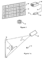
- Figures 1 and 1a illustrate a minimal 2x2x2 holographic volumetric display.
- the preferred embodiment is figure 1 , where the holographic screen 28 is illuminated by a programmable lighting means comprising an image pattern generation unit 20 connected to a colour digital projector 26 via a video interface 24.
- the image pattern generation unit 20 receives a rendered 3D image as a set of voxel descriptions 22.
- the holographic screen contains sub-holograms made out of a matrix of holographic tiles 30 that reconstruct the voxels 32 when the sub-holograms are illuminated by the programmable lighting means.
- Figure 1a shows a side-on view of the projector 26, holographic screen 28, voxels 32, viewer 35 and light beams 37 and 38.
- the projector 26 illuminates the holographic screen 28 via the light beams 37.
- the light beams 38 reflect off the sub-holograms on the holographic screen 28 and reconstruct the voxels 32 in front of the viewer 35.
- any sub-hologram can reconstruct any 3D shape at any location outside the plane of the holographic screen within the constraints of the manufacturing parameters of the holographic screen.
- the sub-holograms may be of different sizes and geometries.
- Sub-holograms may be spread out across the surface of the holographic screen and they may be composed of even smaller holograms or holographic tiles.
- each sub-hologram has the sampled interference pattern of a three dimensional cube pre-recorded on it that corresponds to a unique holographic voxel positioned in front of the holographic screen when it is illuminated via the projector.
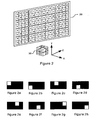
- the mapping of sub-holograms and holographic tiles to voxels are depicted in figure 2 .
- the holographic screen 29 contains a 4x4 grid of holographic tiles, with each tile comprising eight holographic sub-tiles, labelled a to h, and the corresponding voxels 39 are labelled A to H.
- the (x,y,z) co-ordinates of the eight voxels are given as follows: A(0,0,0) B(0,1,0) C(1,0,0) D(1,1,0) E(0,0,1), F(0,1,1) G(1,0,1) H(1,1,1). Note that voxel E cannot be seen in figure 2 as it is located below voxel F.
- the illumination patterns for each holographic sub-tile are shown in figures 2a to 2h .
- the black areas imply no light whilst the white areas imply illumination.
- Figure 3 shows an example of how sub-holograms can be made from the holographic tiles.
- Each sub-hologram can reconstruct the voxels labelled A to H in figure 2 .
- the holographic tiles and sub-holograms are spatially multiplexed across the surface of the holographic screen.
- the 3D image is represented as a collection of voxels by (x,y,z) co-ordinates and a set of primary colours with red, green and blue [r,g,b] parameters.
- the primary colours can be represented by normalised values between 0 and 1.0 where 0 means no colour and 1.0 means a pure colour.
- 0 means no colour and 1.0 means a pure colour.
- [1,0,0] is red
- [1,1,1] is white
- [0,0,0] is black
- [0.5, 0.5, 0.5] is grey
- [0,1,1] is cyan and so on.
- Red, green and blue voxels occupy the same space so they can be recombined with varying degrees of luminosity to present any visible colour to the human eye.
- the role of the image pattern generation unit 20 is to map a rendered 3D volumetric image, comprising any set of voxels A to H, on to the holographic screen 28. It receives a set of voxels and colours via the digital interface 22. The image pattern generation unit then creates a superposition the patterns given in figures 2a to 2h and applies the colours, which it then displays on the colour digital projector 26. For example, a white "L" shaped image could comprise the voxels A, B and C in figure 2 . The co-ordinates and colours for this shape are given by: (0,0,0)[1,1,1] ; (0,1,0)[1,1,1]; (1,0,0)[1,1,1].
- the corresponding illumination pattern is a superposition of the patterns given in figures 3a, 3b and 3c , based on the holographic sub-tiles in figures 2a, 2b and 2c .
- This pattern is projected on to the holographic screen as shown in figure 4a .
- the corresponding 3D image is reconstructed as the 'L' shaped voxels.
- a different yellow "L" shaped 3D image could comprise the voxels E, F and G in figure 2 (note that voxel E is not visible in the figure), corresponding to the (x,y,z)[r,g,b] values: (0,0,1)[1,1,0] ; (0,1,1)[1,1,0] ; (1,0,1)[1,1,0].
- the illumination pattern is given by the superposition of figures 3e, 3f and 3g , based on the holographic sub-tiles in figures 2e, 2f and 2g , and applying the colour yellow to the white areas of the superposed image.
- the voxels may be used to create 2D as well as 3D holographic displays, or a combination of both.
- the voxels can be any size or shape and it is even possible for two or more voxels to occupy the same volume where an individual voxel can be selected by different illumination patterns on the holographic screen. If such a holographic screen is illuminated uniformly then all voxels will be visible.
- An example of such overlaid voxels could be currency symbols: $, €, £ and ⁇ .
- the sub-holograms are shown in figures 5a to 5d corresponding to the symbols $, €, £ and ⁇ .
- the holographic tiles are horizontal slits across the length of the holographic screen. Each symbolic voxel is reconstructed by a number of horizontal slits. If the whole holographic screen is illuminated then all voxels will appear but they will be superimposed upon each other, since they occupy the same space, as shown in figure 5e . Such an assembly of voxels is not intelligible. However, if the holographic screen is illuminated with one of the sub-holograms in figures 5a to 5d then only the corresponding currency symbol will be shown. This is shown in figure 5f for the € symbol corresponding to the sub-hologram of figure 5b .
- FIG. 6a shows an example of a voxel-based display of the popular seven segment display for the digits 0 to 9 plus a dot.
- each voxel represents a single segment labelled a to h in figure 6a .
- These voxel segments may be recorded on to the sub-holograms and holographic tiles shown in figure 6b . If such a holographic screen is illuminated then all voxel segments will appear like the digit 8 plus a dot.
- the digit 3 consists of the voxel segments a, b, c, d, g which correspond to similarly labelled sub-tiles in figure 6b.
- Figure 6c shows how the illumination pattern displays the digit 3 as a reconstruction of segmented voxels.
- Voxels may be used to construct other types of 2D style displays such as segmented displays, dot-matrix displays, gauges, bar graphs, fixed text messages, letters, numerals, signs, icons or symbols e.g. currency or mathematical symbols.
- Holograms need to be carefully illuminated by a bright light source with the correct spectral properties in order to clearly show the stored 3D image.
- the light source has to be positioned within a narrow range of angles to the plane of the hologram. If these conditions are not met then the stored 3D image will not be correctly reconstructed, if at all.
- the invention exploits these properties of holograms to selectively illuminate groups of sub-holograms by means of two dimensional patterns projected on to the holographic screen. If there is an absence of light i.e. where the projected 2D image is black then the sub-hologram will not be illuminated and it cannot therefore reconstruct the corresponding voxel. In this manner, voxels can be rendered either visible or hidden i.e. switched on or off through selective illumination.
- the image pattern generation unit takes rendered 3D images as sets of voxel descriptions in terms of co-ordinates and colours to produce illumination patterns corresponding to the shapes of the sub-holograms in figures 3a to 3h .
- the image pattern generation unit may be implemented by those skilled in the art of computer graphics software and digital image processing hardware.
- the image pattern generation unit converts voxel descriptions to images via the following steps:
- the image pattern generation unit may be implemented as a computer connected to a display unit.
- the 3D images and voxel descriptions may be generated by an external algorithm or they may be received via any input interface such as a keyboard, network or local disc.
- a computer-implemented version of the image pattern generator may receive the 3D image as an array of voxels in step1 above.
- the algorithm may use tiles to make the sub-hologram patterns corresponding to voxels in step 2 by means of a lookup table that maps each voxel to a tile description.
- the tile description contains geometric information about how to generate a tile e.g. in terms of polygon vertices of the holographic sub-tiles as in figures 2a to 2h .
- the remaining steps 3, 4 and 5 are relatively straightforward to implement.
- Step 5 needs to be executed in a timeframe consistent with the human persistence of vision to give the illusion of motion.
- the algorithm may be realised by means of a graphics language such as OpenGL or other graphics library APIs included with popular computer languages such as C, C++, Java or Python.
- a hardware implementation of the image pattern generation unit may be based on a computational device such as a DSP, CPU or micro-controller.
- a computational device such as a DSP, CPU or micro-controller.
- the program and pattern memories may be read-only memories which respectively hold the software algorithms and the sub-hologram patterns as bitmaps.
- the read-write random access memory (RAM) holds the working memory for variables as well as an image memory.
- the framebuffer is an area of memory accessible to the video output hardware.
- the 3D image is received as an array of digitised rendered voxel co-ordinates and colours via the digital interface.
- the voxels are decoded and held in the working RAM as an array. Once all voxels are received, the framebuffer is cleared to black.
- the second step is to lookup the sub-hologram pattern in the pattern memory corresponding to the voxel and load it into the image memory.
- the third step is to apply the voxel colour to the white areas of the sub-hologram pattern in the image memory.
- the image memory is added to the existing contents of the framebuffer. These three steps are repeated for all voxels. Finally, the framebuffer is output to the display device.
- FIG 7b A hardware implementation of the image pattern generation unit is illustrated in figure 7b .
- the architecture of this implementation is based on memories and logic processing blocks.
- the implementation may be realised in discrete logic or field programmable gate array devices.
- the 3D image is received as an array of digitised rendered voxel co-ordinates and colours via the digital interface.
- the voxels are decoded and held in a FIFO memory buffer for each 3D image.
- the 'apply colour' block loads a pattern corresponding to a voxel into the image buffer and then applies the colour to the pattern in the image buffer.
- the image accumulator block takes the contents of the image buffer and adds it to the current image in the accumulator.
- the pattern accumulation sequence is done for all voxels which results in a combination of all the sub-hologram patterns. This final pattern is sent to the display device via the video interface.
- the controller block manages the control and sequencing of the data flow from start to finish, beginning with the input voxels and ending with the video interface. The controller repeats the entire sequence for moving images.
- the hardware implementations require a means to receive instructions from an external host computer for control and configuration of the image pattern generation unit. This may be done via the digital interface 22 which can be implemented as a computer network interface, a serial bus interface or a wireless interface. Instructions may include uploading new program code or logic firmware, reset, configuration parameters, sub-hologram patterns, holographic screen size, number of holographic screens, image sequencing etc.
- the configuration operations may include operations such as initialising the pattern memories for various types of holographic screens.
- the holographic screen can be readily manufactured via a variety of prior art methods by those skilled in the art of optical holography.
- a basic method for making a monochromatic holographic screen is described herein.
- the sub-holograms on the holographic screen are based on the principle of transfer holograms or image holography. This is a two-stage process where a hologram of a hologram is made.
- a master transmission hologram, known as H1 is recorded which acts as the object for a second reflection hologram, known as H2.
- H2 second reflection hologram
- holographic film is preferable to holographic plates.
- the principle is illustrated in figure 8 .
- H1 is first recorded as a master transmission hologram with a laser reference beam 40 incident at an angle of 45 degrees on the surface of H1 and object beam 42 represents a voxel 44 in the shape of a cube.
- object beam 42 represents a voxel 44 in the shape of a cube.
- H1 is recorded, processed and developed, it is flipped by 180 degrees for recording the stored image on to the H2 hologram 46.
- H2 is sandwiched between a pair of identical masks 48 and is recorded with laser reference beams 50 and object beam 56 from the reconstructed holographic voxel 54.
- H2 is much larger than H1 to compensate for the reduction in recording surface area due to the masks 48.
- the holographic voxel on H1 is recorded eight times in eight different positions in 3D (x,y,z) space on to H2 with eight different masks.
- the position of H2 is fixed.
- the masks correspond to the patterns in figures 3a to 3h .
- the voxel recording configuration is illustrated in figure 8a and the process is described as follows:
- a hologram generally contains diffraction patterns of the 3D image across its entire surface area. If one part of such a hologram is removed then it still contains the 3D image but only from its own unique perspective. This is equivalent to placing a mask with a single hole in front of a hologram so the 3D image is viewable from the perspective of the hole.
- a series of such holes correspond to the holographic sub-tiles shown in figures 2a to 2h and a series of masks corresponding to sub-holograms are shown in figures 3a to 3h .
- the sub-hologram is a spatially sub-sampled version of a full hologram of the voxel 54, with the holographic tile topology determining the nature of the sub-sampling.
- colour holograms There are numerous prior art methods for constructing colour holograms described in the literature. Many of these methods are applicable to the construction of the holographic screen with sub-holograms.
- the preferred embodiment of the holographic screen and its sub-holograms is via colour reflection holograms where each voxel is white in colour and is composed of the three primary colours: red, green and blue.
- Reflection holograms have the advantage that they can be illuminated by ordinary light sources such as tungsten, halogen or metal halide lamps commonly found in projectors.
- the holographic screen may equally be implemented as a transmission hologram but it would then require illumination by coherent light sources such as colour laser-based projectors.
- a simple colour extension of the monochromatic method described here is to make three H1 and H2 holograms using red, green and blue lasers respectively, using films sensitive to these colours.
- the three developed H2 reflection holograms are then stacked to make a final composite holographic screen with colour sub-holograms and voxels.
- the sub-hologram is illuminated with red, green and blue light sources with the same wavelengths as the lasers used to create the H2 holograms.
- the recorded red, green and blue voxels are reconstructed in the same volume of space, thereby creating a white voxel.
- This white voxel can be used to recreate any colour visible to the human eye by varying the intensities of the constituent red, green and blue light sources.
- An effective embodiment of the holographic screen would be to numerically compute the diffraction patterns for each sub-hologram and its corresponding voxel in 3D space. These patterns can then be printed directly on the surface of a suitable substrate such as silica, polymer or other holographic materials using embossing, lithographic or photo-reduction techniques. This method is effective for transmission holograms as the diffraction patterns only need to be printed on one surface whereas reflection holograms would require several layers.
- holographic printing technologies from companies like Geola, Spatial Imaging and Zebra Imaging.
- Holoprinters use a variety of techniques to produce multiplexed stereographic holograms from various sources including simulated 2D computer images, from multiple angles.
- the holograms produced in this manner are high quality full colour reflection holograms.
- the holographic screen may be produced by means of a holoprinter by interleaving a series of computer-generated voxels from a variety of perspectives and positions on to the holographic stereogram.
- the voxels can be made to appear in front, behind or on the holographic screen; or a combination of these. If the voxels are reconstructed in front of the holographic screen then the 3D image appears to be floating in mid-air; this is known as a real image. Otherwise, if the voxels are reconstructed behind the holographic screen then the 3D image would be encapsulated within the screen, rather like looking at the image through a window; this is known as a virtual image.
- the colour digital projector is readily available as prior art. These projectors usually take an analogue or digital video signal as input and project an image on to a flat projection screen. These projectors use a bright light source, together with suitable optics and active components to project a two dimensional images on to a plain white or silvered projection screen.
- the light source is usually a metal halide lamp that produces bright light with good colour temperature characteristics and a broad spectrum.
- the internal optics usually consists of prisms, colour filters, dichroic mirrors and lenses.
- the most common active components are based on liquid-crystal technology (LCD panels or LCOS) or DLP technology based on digital micromirrors. Such projectors are suitable for illuminating reflection holograms.
- laser projectors use similar optics and active components except that they do not require a separate lamp as these components are driven directly by primary colour lasers.
- Laser projectors are suitable for illuminating transmission holograms. Projectors usually incorporate fans for cooling the light source, hence this is the only moving part within the projection-based volumetric holographic display.
- the size of the image produced by the projector has to be at least as large as the holographic screen.
- the resolution of the projector needs to produce the sub-holograms and holographic tiles with sufficient accuracy.
- As holograms reconstruct 3D images due to diffraction or Bragg reflection, only a small portion of the incident light energy is actually used to reconstruct the 3D image. Hence, it is important to use projectors or LCDs with high intensity light sources to reconstruct the voxels.
- the projector required by the invention needs to be suitably modified to work with the holographic screen.
- the primary colours used within the projector need to match the primary colours of the holographic screen.
- the internal optics of the projector including colour filters, prisms or other dichroic components need to match the frequencies of the red, green and blue lasers that created the holographic screen.
- Most digital projectors include keystone correction feature which corrects the angular distortion of the projected image when the projector is angled with respect to the screen.
- the projector needs to be angled with respect to the holographic screen such that the angle of incidence matches the reference beams used to create the hologram.
- the projector needs to provide sufficient keystone correction for this angular distortion.
- the colour LCD panel 36 is readily available as prior art.
- An LCD panel typically comprises an active matrix of TFTs on a glass substrate with transparent electrodes.
- TFTs for a colour LCD panel, there are three transistors per pixel with red, green and blue filters to produce colour.
- the other components of the LCD panel include the liquid crystal material sandwiched between a glass panel and the active matrix panel.
- a TFT on the active matrix When activated, it produces a voltage across the liquid crystal material that changes the orientation of the liquid crystal, which changes the polarisation of any light passing through the liquid crystal. If the light incident on the TFT is also polarised then it will either be transmitted or blocked, depending on the orientation of the crystals.
- the display-based embodiments in figures 9 and 9a have no moving parts.
- the projector is replaced by a bright light source 31 with a polarising filter 33 that illuminates a LCD panel 36 which is placed in front of the holographic screen 28.
- the image pattern generation unit 20 drives the LCD panel 36 via a video interface.
- the LCD panel 36 acts as a mask or shutter for the polarised light source.
- the default configuration of the LCD panel is opaque so no polarised light reaches the holographic screen.
- the image pattern generation unit makes transparent colour patterns on the LCD panel that expose the underlying sub-holograms to the polarised light source that enable the voxels 32 to be reconstructed.
- the light source may be based on halogen or metal halide or other bright lamp technologies.
- the lamp and polarising filter needs to be angled with respect to the holographic screen such that the angle of incidence of the light matches the reference beams used to create the holographic screen.
- the size of the LCD panel has to be at least as large as the holographic screen.
- the resolution of the LCD panel has to produce the sub-holograms and holographic tiles with sufficient accuracy.
- the LCD panel needs to be configured such that the default state is opaque. This may be achieved by placing a polarising filter covering the LCD panel with the same polarisation as the polarising filter 31, such that the orientation of both polarisers is orthogonal to the polarisation of the liquid crystal.
- the red, green and blue filters on the LCD panel need to be adapted to match the red, green and blue lasers used to create the holographic screen.
- FIG. 9a An alternative embodiment is depicted in figure 9a , which is based on an emissive display panel 33 behind the holographic screen 28.
- the image pattern generation unit 20 is connected to the video input of the light emitting display.
- the configuration acts as a true programmable light source as any display panel element can emit light.
- the image pattern generation unit makes the sub-hologram patterns on the emissive display which directly illuminate the sub-holograms that enable the voxels 32 to be reconstructed.
- the size and resolution requirements of the light emitting display are similar to the LCD panel.
- the emissive display panel may be based on a CRT display, colour LED display, OLED (organic light-emitting diode) display, or a colour laser diode display.
- the frequencies of the primary colours of the emissive display panel need to match those of the holographic screen.
- the emissive display panel needs to be optically coupled to the holographic screen such that the angle of the incident light matches the reference beams used to create the holographic screen.
- a simple all-mechanical embodiment of the invention could use a mechanical movie projector with a series of sub-hologram images pre-recorded on a film which together act as a programmable illumination means with a static set of patterns. This configuration enables a pre-recorded set of 3D images to be displayed.
- the image pattern generation unit may be integrated within electronics of the displays device such as the projector, LCD panel or emissive display panel.
- the digital input 12 of the image pattern generation unit may be implemented as a network interface within the display device for receiving instructions, configuration information and voxels.
- the holographic volumetric display may be scaled in several ways.
- the simplest method is shown figure 10 where two holographic screens are placed side by side.
- This example shows two instances of the segmented volumetric display from figure 6a and the holographic screen from figure 6b .
- the pair of holographic screens may be illuminated by the same projector with the image pattern generation unit suitably modified to take both screens into account. This includes mapping voxel co-ordinates across both holographic screens. In this manner, two or more different holographic screens may be stacked in the same plane to produce larger holographic volumetric displays.
- the holographic volumetric display may also be scaled in three dimensions by placing holographic screens as shown in figure 10a which depicts a 4x4x2 voxel display as an arrangement of four 2x2x2 displays.
- figure 10a depicts a 4x4x2 voxel display as an arrangement of four 2x2x2 displays.
- This example is based on the LCD panel embodiment of figure 9 , with four separate panels, one for each holographic volumetric display.
- the arrangement also requires a polarised light source not shown in figure 10a .
- the modified image pattern generation unit 21 needs to take all holographic screens into account by including a driver to interface with four video connections and correctly applying voxel co-ordinates across the volumetric displays. In such a configuration, it would be advantageous to have the image pattern generation units integrated within the display device and to access all screens via a network interface from a host computer.
- the holographic screen may be any planar shape of any size and the image pattern generation unit needs to know about the geometry of the holographic screen as well as the features of the display device. It is also possible to have holographic screens that are curved or even cylindrical. Such displays require projectors with adapted optics or additional signal processing to project the sub-hologram images on to the holographic screen.
Applications Claiming Priority (3)
| Application Number | Priority Date | Filing Date | Title |
|---|---|---|---|
| GB0804280A GB0804280D0 (en) | 2008-03-07 | 2008-03-07 | A three dimensional holographic volumetric display |
| GB0804383A GB0804383D0 (en) | 2008-03-10 | 2008-03-10 | A three dimensional holographic volumetric display |
| PCT/GB2009/050224 WO2009109785A2 (en) | 2008-03-07 | 2009-03-05 | A three dimensional holographic volumetric display |
Publications (2)
| Publication Number | Publication Date |
|---|---|
| EP2274653A2 EP2274653A2 (en) | 2011-01-19 |
| EP2274653B1 true EP2274653B1 (en) | 2015-05-06 |
Family
ID=40589789
Family Applications (1)
| Application Number | Title | Priority Date | Filing Date |
|---|---|---|---|
| EP09716381.0A Active EP2274653B1 (en) | 2008-03-07 | 2009-03-05 | A three dimensional holographic volumetric display |
Country Status (4)
| Country | Link |
|---|---|
| US (1) | US8625183B2 (ja) |
| EP (1) | EP2274653B1 (ja) |
| JP (1) | JP2011513786A (ja) |
| WO (1) | WO2009109785A2 (ja) |
Families Citing this family (33)
| Publication number | Priority date | Publication date | Assignee | Title |
|---|---|---|---|---|
| US20120287490A1 (en) * | 2010-11-05 | 2012-11-15 | Zebra Imaging, Inc. | Displaying 3D Imaging Sensor Data on a Hogel Light Modulator |
| US8633969B2 (en) * | 2011-02-09 | 2014-01-21 | Omnivision Technologies, Inc. | Apparatus and method for three-dimensional image capture with extended depth of field |
| KR101826741B1 (ko) * | 2011-08-24 | 2018-02-07 | 삼성전자주식회사 | 홀로그래픽 3차원 영상의 프린팅 방법 |
| CN103782592B (zh) * | 2011-09-14 | 2016-09-28 | 英特尔公司 | 全息显示系统、方法和装置 |
| KR101867814B1 (ko) * | 2011-09-22 | 2018-06-18 | 엘지전자 주식회사 | 이동 단말기 및 그 제어방법 |
| KR20130085553A (ko) * | 2011-12-20 | 2013-07-30 | 한국전자통신연구원 | 프로젝션 기반의 디지털 홀로그램 디스플레이 시스템 및 그 방법 |
| SG11201405937XA (en) * | 2012-03-26 | 2014-10-30 | Mantisvision Ltd | Three dimensional camera and projector for same |
| US9423770B2 (en) * | 2012-11-13 | 2016-08-23 | Empire Technology Development Llc | Holographic imaging |
| US8988343B2 (en) | 2013-03-29 | 2015-03-24 | Panasonic Intellectual Property Management Co., Ltd. | Method of automatically forming one three-dimensional space with multiple screens |
| WO2014193480A1 (en) * | 2013-05-28 | 2014-12-04 | Fusao Ishii | High contrast projection screen |
| US20150062294A1 (en) * | 2013-08-27 | 2015-03-05 | Thomas S. Sibley | Holoscope: Digital Virtual Object Projector |
| JP6289194B2 (ja) * | 2014-03-20 | 2018-03-07 | オリンパス株式会社 | ホログラムデータ生成方法、ホログラム画像再生方法およびホログラム画像再生装置 |
| US10048647B2 (en) | 2014-03-27 | 2018-08-14 | Microsoft Technology Licensing, Llc | Optical waveguide including spatially-varying volume hologram |
| US10169909B2 (en) * | 2014-08-07 | 2019-01-01 | Pixar | Generating a volumetric projection for an object |
| JP6428501B2 (ja) * | 2015-06-24 | 2018-11-28 | 株式会社Jvcケンウッド | 映像信号処理装置及び投射型表示装置 |
| US10210844B2 (en) | 2015-06-29 | 2019-02-19 | Microsoft Technology Licensing, Llc | Holographic near-eye display |
| GB201513333D0 (en) | 2015-07-29 | 2015-09-09 | Khan Javid | Volumetric display |
| US10310335B2 (en) | 2016-02-29 | 2019-06-04 | Microsoft Technology Licensing, Llc | Reducing orders of diffraction patterns |
| US10254542B2 (en) | 2016-11-01 | 2019-04-09 | Microsoft Technology Licensing, Llc | Holographic projector for a waveguide display |
| RU2650086C1 (ru) * | 2016-12-22 | 2018-04-06 | Самсунг Электроникс Ко., Лтд. | Устройство отображения голографических изображений и способ функционирования блока управления, содержащегося в нем |
| US10474103B2 (en) * | 2016-12-27 | 2019-11-12 | Universal City Studios Llc | Holographic image apparatus for high depth of field holograms |
| US11022939B2 (en) | 2017-01-03 | 2021-06-01 | Microsoft Technology Licensing, Llc | Reduced bandwidth holographic near-eye display |
| US10244204B2 (en) | 2017-03-22 | 2019-03-26 | International Business Machines Corporation | Dynamic projection of communication data |
| US10691066B2 (en) | 2017-04-03 | 2020-06-23 | International Business Machines Corporation | User-directed holographic object design |
| US10325414B2 (en) | 2017-05-08 | 2019-06-18 | Microsoft Technology Licensing, Llc | Application of edge effects to 3D virtual objects |
| US10712567B2 (en) | 2017-06-15 | 2020-07-14 | Microsoft Technology Licensing, Llc | Holographic display system |
| KR102005522B1 (ko) * | 2017-07-12 | 2019-07-30 | 에스케이텔레콤 주식회사 | 스크린 장치 |
| RU2686576C1 (ru) * | 2017-11-30 | 2019-04-29 | Самсунг Электроникс Ко., Лтд. | Компактное устройство голографического дисплея |
| US11097199B2 (en) | 2018-11-09 | 2021-08-24 | Prism Holograms Llc | Devices and methods for holographic screen suspension systems |
| US11165662B2 (en) | 2019-03-26 | 2021-11-02 | International Business Machines Corporation | Enabling interactive cable routing and planning optimization for customized hardware configurations |
| US11051001B2 (en) * | 2019-05-29 | 2021-06-29 | Avigilon Corporation | Method and system for generating a two-dimensional and a three-dimensional image stream |
| AU2020298331A1 (en) * | 2019-06-20 | 2022-01-27 | Prism Holograms Llc | Three-dimensional volumetric holographic display |
| CN114708403A (zh) * | 2020-12-16 | 2022-07-05 | 高勇 | 一种互动投影输入输出设备 |
Citations (1)
| Publication number | Priority date | Publication date | Assignee | Title |
|---|---|---|---|---|
| WO1988005174A1 (en) * | 1987-01-06 | 1988-07-14 | Hughes Aircraft Company | Segmented 3-d hologram display |
Family Cites Families (19)
| Publication number | Priority date | Publication date | Assignee | Title |
|---|---|---|---|---|
| JPH0373967A (ja) | 1989-08-16 | 1991-03-28 | Konica Corp | コーティングキャリア |
| JPH0373967U (ja) * | 1989-11-22 | 1991-07-25 | ||
| US5103325A (en) | 1990-10-01 | 1992-04-07 | Xerox Corporation | Segmented hologram for multi-image display |
| US5191449A (en) * | 1992-02-03 | 1993-03-02 | Cfc Applied Holographics | Animated holographic stereogram display |
| US7132200B1 (en) * | 1992-11-27 | 2006-11-07 | Dai Nippon Printing Co., Ltd. | Hologram recording sheet, holographic optical element using said sheet, and its production process |
| JP3412875B2 (ja) * | 1993-09-21 | 2003-06-03 | 大日本印刷株式会社 | ホログラム記録シート、該シートを用いたホログラフィックオプティカル素子 |
| US5734485A (en) * | 1995-04-25 | 1998-03-31 | Rocky Research | Large display composite holograms and methods |
| JP3500404B2 (ja) * | 1996-12-12 | 2004-02-23 | シャープ株式会社 | 要素ホログラムパネル及びそれに用いられる要素ホログラムの記録方法 |
| JPH10332917A (ja) * | 1997-06-02 | 1998-12-18 | Sharp Corp | 回折素子パネル及びそれから構成される三次元画像表示装置 |
| GB9713658D0 (en) | 1997-06-28 | 1997-09-03 | Travis Adrian R L | View-sequential holographic display |
| GB2330471A (en) | 1997-10-15 | 1999-04-21 | Secr Defence | Production of moving images for holography |
| JPH11194702A (ja) * | 1997-11-04 | 1999-07-21 | Harness Syst Tech Res Ltd | 表示装置および表示装置におけるホログラム再生方法 |
| JPH11242120A (ja) * | 1998-02-25 | 1999-09-07 | Sharp Corp | 要素ホログラムパネル及び該要素ホログラムパネルを用いた再生像生成装置 |
| GB2350962A (en) | 1999-06-09 | 2000-12-13 | Secr Defence Brit | Holographic displays |
| LT4842B (lt) * | 1999-12-10 | 2001-09-25 | Uab "Geola" | Hologramų spausdinimo būdas ir įrenginys |
| AU2439001A (en) | 1999-12-16 | 2001-06-25 | Reveo, Inc. | Three-dimensional volumetric display |
| JP4793711B2 (ja) * | 2001-07-09 | 2011-10-12 | スタンレー電気株式会社 | ホログラムディスプレイ |
| CN100422851C (zh) * | 2005-12-23 | 2008-10-01 | 深圳市泛彩溢实业有限公司 | 一种全息投影屏及其制作方法、系统和应用 |
| JP2010507824A (ja) | 2006-10-26 | 2010-03-11 | シーリアル テクノロジーズ ソシエテ アノニム | ホログラフィック・ディスプレイ装置 |
-
2009
- 2009-03-05 JP JP2010549200A patent/JP2011513786A/ja active Pending
- 2009-03-05 EP EP09716381.0A patent/EP2274653B1/en active Active
- 2009-03-05 US US12/736,021 patent/US8625183B2/en active Active
- 2009-03-05 WO PCT/GB2009/050224 patent/WO2009109785A2/en active Application Filing
Patent Citations (1)
| Publication number | Priority date | Publication date | Assignee | Title |
|---|---|---|---|---|
| WO1988005174A1 (en) * | 1987-01-06 | 1988-07-14 | Hughes Aircraft Company | Segmented 3-d hologram display |
Also Published As
| Publication number | Publication date |
|---|---|
| US8625183B2 (en) | 2014-01-07 |
| WO2009109785A2 (en) | 2009-09-11 |
| WO2009109785A3 (en) | 2009-11-26 |
| EP2274653A2 (en) | 2011-01-19 |
| JP2011513786A (ja) | 2011-04-28 |
| US20110002020A1 (en) | 2011-01-06 |
Similar Documents
| Publication | Publication Date | Title |
|---|---|---|
| EP2274653B1 (en) | A three dimensional holographic volumetric display | |
| US10469837B2 (en) | Volumetric display | |
| JP6349282B2 (ja) | ホログラムを計算する方法 | |
| US5745197A (en) | Three-dimensional real-image volumetric display system and method | |
| US8075138B2 (en) | System and methods for angular slice true 3-D display | |
| JP4743966B2 (ja) | 画像表示装置 | |
| US20070242237A1 (en) | System and Methods for Angular Slice True 3-D Display | |
| US10070106B2 (en) | Optical system designs for generation of light fields using spatial light modulators | |
| CN111417903B (zh) | 全息显示器和全息图像形成方法 | |
| KR20080096505A (ko) | 비디오 홀로그램용 디스플레이 장치에 화상 내용을멀티모드로 표시하기 위한 방법 및 멀티모드 디스플레이장치 | |
| JP2002506590A (ja) | 自動立体画像表示装置 | |
| KR20170073119A (ko) | 홀로그램 기반의 입체 영상 표시 장치 | |
| Nordin et al. | Three-dimensional display utilizing a diffractive optical element and an active matrix liquid crystal display | |
| US20230121150A1 (en) | Display panel | |
| KR102664928B1 (ko) | 홀로그래픽 디스플레이 및 홀로그래픽 이미지 형성 방법 | |
| Kompanets et al. | Volumetric displays | |
| Sholler et al. | True 3D displays for avionics and mission crewstations | |
| WO2024028593A1 (en) | Holographic display system and method for expanding a display region | |
| Kornev et al. | New layouts for laser liquid-crystal projection displays | |
| Pen et al. | Multi-image stereograms in 3D visualization | |
| JP2010066387A (ja) | 立体像表示装置および立体像表示装置作製方法 |
Legal Events
| Date | Code | Title | Description |
|---|---|---|---|
| PUAI | Public reference made under article 153(3) epc to a published international application that has entered the european phase |
Free format text: ORIGINAL CODE: 0009012 |
|
| 17P | Request for examination filed |
Effective date: 20101005 |
|
| AK | Designated contracting states |
Kind code of ref document: A2 Designated state(s): AT BE BG CH CY CZ DE DK EE ES FI FR GB GR HR HU IE IS IT LI LT LU LV MC MK MT NL NO PL PT RO SE SI SK TR |
|
| AX | Request for extension of the european patent |
Extension state: AL BA RS |
|
| DAX | Request for extension of the european patent (deleted) | ||
| 17Q | First examination report despatched |
Effective date: 20111010 |
|
| REG | Reference to a national code |
Ref country code: DE Ref legal event code: R079 Ref document number: 602009031073 Country of ref document: DE Free format text: PREVIOUS MAIN CLASS: G03H0001300000 Ipc: G03H0001220000 |
|
| GRAP | Despatch of communication of intention to grant a patent |
Free format text: ORIGINAL CODE: EPIDOSNIGR1 |
|
| RIC1 | Information provided on ipc code assigned before grant |
Ipc: G03H 1/30 20060101ALI20140630BHEP Ipc: G03H 1/04 20060101ALI20140630BHEP Ipc: G03H 1/22 20060101AFI20140630BHEP Ipc: G03H 1/26 20060101ALI20140630BHEP Ipc: G03H 1/20 20060101ALI20140630BHEP |
|
| INTG | Intention to grant announced |
Effective date: 20140728 |
|
| GRAS | Grant fee paid |
Free format text: ORIGINAL CODE: EPIDOSNIGR3 |
|
| GRAP | Despatch of communication of intention to grant a patent |
Free format text: ORIGINAL CODE: EPIDOSNIGR1 |
|
| RAP1 | Party data changed (applicant data changed or rights of an application transferred) |
Owner name: KHAN, JAVID |
|
| RIN1 | Information on inventor provided before grant (corrected) |
Inventor name: KHAN, JAVID |
|
| INTG | Intention to grant announced |
Effective date: 20150120 |
|
| GRAA | (expected) grant |
Free format text: ORIGINAL CODE: 0009210 |
|
| AK | Designated contracting states |
Kind code of ref document: B1 Designated state(s): AT BE BG CH CY CZ DE DK EE ES FI FR GB GR HR HU IE IS IT LI LT LU LV MC MK MT NL NO PL PT RO SE SI SK TR |
|
| REG | Reference to a national code |
Ref country code: GB Ref legal event code: FG4D |
|
| REG | Reference to a national code |
Ref country code: CH Ref legal event code: EP |
|
| REG | Reference to a national code |
Ref country code: IE Ref legal event code: FG4D |
|
| REG | Reference to a national code |
Ref country code: AT Ref legal event code: REF Ref document number: 726125 Country of ref document: AT Kind code of ref document: T Effective date: 20150615 |
|
| REG | Reference to a national code |
Ref country code: DE Ref legal event code: R096 Ref document number: 602009031073 Country of ref document: DE Effective date: 20150618 |
|
| REG | Reference to a national code |
Ref country code: AT Ref legal event code: MK05 Ref document number: 726125 Country of ref document: AT Kind code of ref document: T Effective date: 20150506 |
|
| REG | Reference to a national code |
Ref country code: NL Ref legal event code: MP Effective date: 20150506 |
|
| REG | Reference to a national code |
Ref country code: LT Ref legal event code: MG4D |
|
| PG25 | Lapsed in a contracting state [announced via postgrant information from national office to epo] |
Ref country code: ES Free format text: LAPSE BECAUSE OF FAILURE TO SUBMIT A TRANSLATION OF THE DESCRIPTION OR TO PAY THE FEE WITHIN THE PRESCRIBED TIME-LIMIT Effective date: 20150506 Ref country code: LT Free format text: LAPSE BECAUSE OF FAILURE TO SUBMIT A TRANSLATION OF THE DESCRIPTION OR TO PAY THE FEE WITHIN THE PRESCRIBED TIME-LIMIT Effective date: 20150506 Ref country code: NO Free format text: LAPSE BECAUSE OF FAILURE TO SUBMIT A TRANSLATION OF THE DESCRIPTION OR TO PAY THE FEE WITHIN THE PRESCRIBED TIME-LIMIT Effective date: 20150806 Ref country code: HR Free format text: LAPSE BECAUSE OF FAILURE TO SUBMIT A TRANSLATION OF THE DESCRIPTION OR TO PAY THE FEE WITHIN THE PRESCRIBED TIME-LIMIT Effective date: 20150506 Ref country code: PT Free format text: LAPSE BECAUSE OF FAILURE TO SUBMIT A TRANSLATION OF THE DESCRIPTION OR TO PAY THE FEE WITHIN THE PRESCRIBED TIME-LIMIT Effective date: 20150907 Ref country code: FI Free format text: LAPSE BECAUSE OF FAILURE TO SUBMIT A TRANSLATION OF THE DESCRIPTION OR TO PAY THE FEE WITHIN THE PRESCRIBED TIME-LIMIT Effective date: 20150506 |
|
| PG25 | Lapsed in a contracting state [announced via postgrant information from national office to epo] |
Ref country code: BG Free format text: LAPSE BECAUSE OF FAILURE TO SUBMIT A TRANSLATION OF THE DESCRIPTION OR TO PAY THE FEE WITHIN THE PRESCRIBED TIME-LIMIT Effective date: 20150806 Ref country code: LV Free format text: LAPSE BECAUSE OF FAILURE TO SUBMIT A TRANSLATION OF THE DESCRIPTION OR TO PAY THE FEE WITHIN THE PRESCRIBED TIME-LIMIT Effective date: 20150506 Ref country code: IS Free format text: LAPSE BECAUSE OF FAILURE TO SUBMIT A TRANSLATION OF THE DESCRIPTION OR TO PAY THE FEE WITHIN THE PRESCRIBED TIME-LIMIT Effective date: 20150906 Ref country code: AT Free format text: LAPSE BECAUSE OF FAILURE TO SUBMIT A TRANSLATION OF THE DESCRIPTION OR TO PAY THE FEE WITHIN THE PRESCRIBED TIME-LIMIT Effective date: 20150506 Ref country code: GR Free format text: LAPSE BECAUSE OF FAILURE TO SUBMIT A TRANSLATION OF THE DESCRIPTION OR TO PAY THE FEE WITHIN THE PRESCRIBED TIME-LIMIT Effective date: 20150807 |
|
| PG25 | Lapsed in a contracting state [announced via postgrant information from national office to epo] |
Ref country code: EE Free format text: LAPSE BECAUSE OF FAILURE TO SUBMIT A TRANSLATION OF THE DESCRIPTION OR TO PAY THE FEE WITHIN THE PRESCRIBED TIME-LIMIT Effective date: 20150506 Ref country code: DK Free format text: LAPSE BECAUSE OF FAILURE TO SUBMIT A TRANSLATION OF THE DESCRIPTION OR TO PAY THE FEE WITHIN THE PRESCRIBED TIME-LIMIT Effective date: 20150506 |
|
| REG | Reference to a national code |
Ref country code: DE Ref legal event code: R097 Ref document number: 602009031073 Country of ref document: DE |
|
| PG25 | Lapsed in a contracting state [announced via postgrant information from national office to epo] |
Ref country code: RO Free format text: LAPSE BECAUSE OF NON-PAYMENT OF DUE FEES Effective date: 20150506 Ref country code: CZ Free format text: LAPSE BECAUSE OF FAILURE TO SUBMIT A TRANSLATION OF THE DESCRIPTION OR TO PAY THE FEE WITHIN THE PRESCRIBED TIME-LIMIT Effective date: 20150506 Ref country code: PL Free format text: LAPSE BECAUSE OF FAILURE TO SUBMIT A TRANSLATION OF THE DESCRIPTION OR TO PAY THE FEE WITHIN THE PRESCRIBED TIME-LIMIT Effective date: 20150506 Ref country code: SK Free format text: LAPSE BECAUSE OF FAILURE TO SUBMIT A TRANSLATION OF THE DESCRIPTION OR TO PAY THE FEE WITHIN THE PRESCRIBED TIME-LIMIT Effective date: 20150506 |
|
| PLBE | No opposition filed within time limit |
Free format text: ORIGINAL CODE: 0009261 |
|
| STAA | Information on the status of an ep patent application or granted ep patent |
Free format text: STATUS: NO OPPOSITION FILED WITHIN TIME LIMIT |
|
| REG | Reference to a national code |
Ref country code: FR Ref legal event code: PLFP Year of fee payment: 8 |
|
| 26N | No opposition filed |
Effective date: 20160209 |
|
| PG25 | Lapsed in a contracting state [announced via postgrant information from national office to epo] |
Ref country code: IT Free format text: LAPSE BECAUSE OF FAILURE TO SUBMIT A TRANSLATION OF THE DESCRIPTION OR TO PAY THE FEE WITHIN THE PRESCRIBED TIME-LIMIT Effective date: 20150506 |
|
| PG25 | Lapsed in a contracting state [announced via postgrant information from national office to epo] |
Ref country code: SI Free format text: LAPSE BECAUSE OF FAILURE TO SUBMIT A TRANSLATION OF THE DESCRIPTION OR TO PAY THE FEE WITHIN THE PRESCRIBED TIME-LIMIT Effective date: 20150506 |
|
| PG25 | Lapsed in a contracting state [announced via postgrant information from national office to epo] |
Ref country code: BE Free format text: LAPSE BECAUSE OF FAILURE TO SUBMIT A TRANSLATION OF THE DESCRIPTION OR TO PAY THE FEE WITHIN THE PRESCRIBED TIME-LIMIT Effective date: 20150506 |
|
| PG25 | Lapsed in a contracting state [announced via postgrant information from national office to epo] |
Ref country code: LU Free format text: LAPSE BECAUSE OF FAILURE TO SUBMIT A TRANSLATION OF THE DESCRIPTION OR TO PAY THE FEE WITHIN THE PRESCRIBED TIME-LIMIT Effective date: 20160305 Ref country code: MC Free format text: LAPSE BECAUSE OF FAILURE TO SUBMIT A TRANSLATION OF THE DESCRIPTION OR TO PAY THE FEE WITHIN THE PRESCRIBED TIME-LIMIT Effective date: 20150506 |
|
| REG | Reference to a national code |
Ref country code: CH Ref legal event code: PL |
|
| REG | Reference to a national code |
Ref country code: IE Ref legal event code: MM4A |
|
| PG25 | Lapsed in a contracting state [announced via postgrant information from national office to epo] |
Ref country code: LI Free format text: LAPSE BECAUSE OF NON-PAYMENT OF DUE FEES Effective date: 20160331 Ref country code: IE Free format text: LAPSE BECAUSE OF NON-PAYMENT OF DUE FEES Effective date: 20160305 Ref country code: CH Free format text: LAPSE BECAUSE OF NON-PAYMENT OF DUE FEES Effective date: 20160331 |
|
| REG | Reference to a national code |
Ref country code: FR Ref legal event code: PLFP Year of fee payment: 9 |
|
| PG25 | Lapsed in a contracting state [announced via postgrant information from national office to epo] |
Ref country code: NL Free format text: LAPSE BECAUSE OF FAILURE TO SUBMIT A TRANSLATION OF THE DESCRIPTION OR TO PAY THE FEE WITHIN THE PRESCRIBED TIME-LIMIT Effective date: 20150506 Ref country code: SE Free format text: LAPSE BECAUSE OF FAILURE TO SUBMIT A TRANSLATION OF THE DESCRIPTION OR TO PAY THE FEE WITHIN THE PRESCRIBED TIME-LIMIT Effective date: 20150506 |
|
| PG25 | Lapsed in a contracting state [announced via postgrant information from national office to epo] |
Ref country code: MT Free format text: LAPSE BECAUSE OF FAILURE TO SUBMIT A TRANSLATION OF THE DESCRIPTION OR TO PAY THE FEE WITHIN THE PRESCRIBED TIME-LIMIT Effective date: 20150506 |
|
| REG | Reference to a national code |
Ref country code: FR Ref legal event code: PLFP Year of fee payment: 10 |
|
| PG25 | Lapsed in a contracting state [announced via postgrant information from national office to epo] |
Ref country code: CY Free format text: LAPSE BECAUSE OF FAILURE TO SUBMIT A TRANSLATION OF THE DESCRIPTION OR TO PAY THE FEE WITHIN THE PRESCRIBED TIME-LIMIT Effective date: 20150506 Ref country code: HU Free format text: LAPSE BECAUSE OF FAILURE TO SUBMIT A TRANSLATION OF THE DESCRIPTION OR TO PAY THE FEE WITHIN THE PRESCRIBED TIME-LIMIT; INVALID AB INITIO Effective date: 20090305 |
|
| PG25 | Lapsed in a contracting state [announced via postgrant information from national office to epo] |
Ref country code: MT Free format text: LAPSE BECAUSE OF FAILURE TO SUBMIT A TRANSLATION OF THE DESCRIPTION OR TO PAY THE FEE WITHIN THE PRESCRIBED TIME-LIMIT Effective date: 20160331 Ref country code: TR Free format text: LAPSE BECAUSE OF FAILURE TO SUBMIT A TRANSLATION OF THE DESCRIPTION OR TO PAY THE FEE WITHIN THE PRESCRIBED TIME-LIMIT Effective date: 20150506 Ref country code: MK Free format text: LAPSE BECAUSE OF FAILURE TO SUBMIT A TRANSLATION OF THE DESCRIPTION OR TO PAY THE FEE WITHIN THE PRESCRIBED TIME-LIMIT Effective date: 20150506 |
|
| PGFP | Annual fee paid to national office [announced via postgrant information from national office to epo] |
Ref country code: FI Payment date: 20190620 Year of fee payment: 5 |
|
| PGFP | Annual fee paid to national office [announced via postgrant information from national office to epo] |
Ref country code: DE Payment date: 20200430 Year of fee payment: 12 |
|
| REG | Reference to a national code |
Ref country code: DE Ref legal event code: R119 Ref document number: 602009031073 Country of ref document: DE |
|
| PG25 | Lapsed in a contracting state [announced via postgrant information from national office to epo] |
Ref country code: DE Free format text: LAPSE BECAUSE OF NON-PAYMENT OF DUE FEES Effective date: 20211001 |
|
| PG25 | Lapsed in a contracting state [announced via postgrant information from national office to epo] |
Ref country code: FR Free format text: LAPSE BECAUSE OF NON-PAYMENT OF DUE FEES Effective date: 20200331 |
|
| REG | Reference to a national code |
Ref country code: GB Ref legal event code: 732E Free format text: REGISTERED BETWEEN 20230803 AND 20230809 |
|
| PGFP | Annual fee paid to national office [announced via postgrant information from national office to epo] |
Ref country code: GB Payment date: 20240109 Year of fee payment: 16 |