EP2274528B1 - Synchro-lock clutch combination friction and mechanical locking clutch - Google Patents
Synchro-lock clutch combination friction and mechanical locking clutch Download PDFInfo
- Publication number
- EP2274528B1 EP2274528B1 EP09733289.4A EP09733289A EP2274528B1 EP 2274528 B1 EP2274528 B1 EP 2274528B1 EP 09733289 A EP09733289 A EP 09733289A EP 2274528 B1 EP2274528 B1 EP 2274528B1
- Authority
- EP
- European Patent Office
- Prior art keywords
- clutch
- dog
- friction
- assembly
- torque
- Prior art date
- Legal status (The legal status is an assumption and is not a legal conclusion. Google has not performed a legal analysis and makes no representation as to the accuracy of the status listed.)
- Active
Links
Images


Classifications
-
- F—MECHANICAL ENGINEERING; LIGHTING; HEATING; WEAPONS; BLASTING
- F16—ENGINEERING ELEMENTS AND UNITS; GENERAL MEASURES FOR PRODUCING AND MAINTAINING EFFECTIVE FUNCTIONING OF MACHINES OR INSTALLATIONS; THERMAL INSULATION IN GENERAL
- F16D—COUPLINGS FOR TRANSMITTING ROTATION; CLUTCHES; BRAKES
- F16D11/00—Clutches in which the members have interengaging parts
- F16D11/14—Clutches in which the members have interengaging parts with clutching members movable only axially
-
- F—MECHANICAL ENGINEERING; LIGHTING; HEATING; WEAPONS; BLASTING
- F16—ENGINEERING ELEMENTS AND UNITS; GENERAL MEASURES FOR PRODUCING AND MAINTAINING EFFECTIVE FUNCTIONING OF MACHINES OR INSTALLATIONS; THERMAL INSULATION IN GENERAL
- F16D—COUPLINGS FOR TRANSMITTING ROTATION; CLUTCHES; BRAKES
- F16D13/00—Friction clutches
- F16D13/22—Friction clutches with axially-movable clutching members
- F16D13/38—Friction clutches with axially-movable clutching members with flat clutching surfaces, e.g. discs
-
- F—MECHANICAL ENGINEERING; LIGHTING; HEATING; WEAPONS; BLASTING
- F16—ENGINEERING ELEMENTS AND UNITS; GENERAL MEASURES FOR PRODUCING AND MAINTAINING EFFECTIVE FUNCTIONING OF MACHINES OR INSTALLATIONS; THERMAL INSULATION IN GENERAL
- F16D—COUPLINGS FOR TRANSMITTING ROTATION; CLUTCHES; BRAKES
- F16D21/00—Systems comprising a plurality of actuated clutches
Definitions
- the present disclosure generally relates to torque transmission components, and more particularly relates to clutches used to transmit torque in vehicles.
- clutches have been used to transmit torque in vehicles.
- multiple clutches are used to engage or disengage selected gearsets to obtain a desired gear ratio.
- the clutches provided for this purpose are typically friction plate clutches, which include a plurality of inner or drive plates that are splined to a rotatable hub.
- a housing or case is coaxially aligned with the hub and supported for rotation independent of the hub.
- a plurality of outer or driven plates are splined to the housing or case and are interposed between the drive plates, such that the drive and driven plates are alternately arranged on a common axis.
- the drive plates include a friction material on one or both sides of the plates.
- An actuator such as a hydraulic piston, applies a pressure force that presses the drive and driven plates into engagement, thereby permitting torque to be transferred from the hub to the housing.
- the number of plates used in a friction plate clutch is typically selected to transmit a maximum desired torque. Due to space constraints and a maximum pressure force that can be generated by the actuator, higher torque transfer is typically achieved by providing additional plates. As a result, friction plate clutches commonly use several plates to meet the maximum torque design. When the clutch is unengaged or idling, however, the plates generate a parasitic drag torque due to the viscous shearing action which exists between the drive and driven plates as they rotate at different speeds relative to one another. This drag torque adversely affects vehicle fuel economy for automatic transmissions, and therefore the use of excessive plates exacerbates this problem.
- the use of numerous friction plates also reduces the controllability of the friction clutch in the lower torque range.
- the relationship between actuator pressure and the amount of torque transfer produced by a friction plate clutch is substantially linear, as illustrated by the dashed line 4 in FIG. 1 .
- the actuator is typically a hydraulic actuator that uses hydraulic fluid to generate the actuator pressure.
- the hydraulic fluid flows through a hydraulic valve, such as a solenoid valve, having a controller operably coupled thereto.
- Synchronizing clutches are known that employ both friction plates and a dog or mechanical connection.
- U.S. Patent No. 6,966,805 to Caldwell discloses a marine transmission having a friction mechanism to at least partially synchronize the rotational speed of a driving shaft and a driven shaft prior to engagement of a dog clutch element. While the friction mechanism transfers some torque, it only begins to rotate the driven shaft so that it is sufficiently synchronized with the driving shaft, and is not intended to operate over any appreciable portion of the operational torque range of the transmission.
- a composite clutch according to the preamble of claim 1 is known from DE 10 2004 017 123 A1 .
- a composite clutch for transmitting an operational range of torques from a driving member to a driven member having a friction clutch assembly.
- the friction clutch assembly includes a number of first friction clutch members coupled to the driving member and a number of second friction clutch members coupled to the driven member.
- the first and second friction clutch members are movable from an unengaged position to a torque transmitting position, wherein the number of first friction clutch members and the number of second friction clutch members are selected to transmit torque across a first portion of the operational range of torques.
- a dog clutch assembly includes a first dog member coupled to the driving member and a second dog member coupled to the driven member, wherein the first and second dog members are movable from a disengaged position to an engaged position in which the first and second dog members mechanically lock with one another.
- An actuator assembly is operatively coupled to the friction clutch assembly and the dog clutch assembly to selectively move the first and second friction clutch members between the unengaged and torque transmitting positions, and to move the first and second dog members between the disengaged and engaged positions.
- a composite clutch for transmitting an operational range of torques from a driving member to a driven member having a friction clutch assembly.
- the friction clutch assembly includes a number of first friction clutch members coupled to the driving member and a number of second friction clutch members coupled to the driven member.
- a dog clutch assembly includes a first dog member coupled to the driving member, a second dog member coupled to the driven member, a dog arm slidably coupled to the second dog member, and a spring disposed between the dog arm and the second dog member biasing the dog arm in a retracted position spaced from the first dog member.
- An actuator assembly is operatively coupled to the dog clutch assembly to selectively cause the first and second friction clutch members to move between the unengaged and torque transmitting positions, and the first and second dog members to move between the disengaged and engaged positions.
- a clutch control system for transmitting an operational range of torques from a driving member to a driven member having a composite clutch with a friction clutch assembly and a dog clutch assembly.
- the composite clutch is operable in a friction clutch mode across a first portion of the operational range of torques and a dog clutch mode across a second portion of the operational range of torques.
- An actuator assembly includes a first actuator operatively coupled to the friction clutch assembly and a second actuator operatively coupled to the mechanical clutch assembly.
- a controller is operably coupled to the actuator assembly and programmed to switch from the friction clutch mode to a dog clutch mode at a transition point associated with a transition torque.
- a composite clutch is disclosed herein that includes both a friction clutch assembly and a dog clutch assembly.
- the friction clutch assembly is used to transmit torque from a driving member to a driven member across a first or lower portion of the operational range of torques.
- the dog clutch assembly is used to transmit torque across a second or upper portion of the operational range of torques.
- the composite clutch may be designed and/or controlled to switch from friction clutch mode to dog clutch mode at a desired transition point.
- the transition point may be selected according to desired operating parameters. Accordingly, output torque is better controlled across the lower portion of the operational range of torques.
- FIG. 2 provides a schematic representation of a composite clutch 20 in a portion of an automatic transmission 22.
- the automatic transmission 22 is but one example of the setting in which the composite clutch 20 may be used.
- Other areas of a transmission, vehicle, machine tool, or other machine could also advantageously employ its teachings as will be readily understood by one of ordinary skill in the art.
- the transmission 22 may include a drive shaft 24 adapted to rotate about an axis 26, which is itself powered by the motive force of an engine (not shown) of a vehicle (also not shown).
- a hub 28 is attached to and rotates with the drive shaft 24.
- the hub 28 may be provided as a simple annular flange coupled to the drive shaft 24 or it may be configured to provide additional features or capabilities, such as a one-way clutch.
- An exterior peripheral surface of the hub 28 is formed with splines 30.
- the transmission 22 may also include a case or housing 32 which is mounted coaxially with the drive shaft 24 and is supported for rotation about the axis 26 independent of the drive shaft 24.
- the drive shaft 24 is the driving or input member while the housing 32 is the driven or output member.
- the composite clutch 20 is provided to transfer torque from the hub 28 to the housing 32.
- the composite clutch 20 includes a friction clutch assembly 34 and a dog clutch assembly 36.
- the friction clutch assembly 34 may include sets of first and second friction members that may be placed in torque transfer engagement.
- one or more inner friction plates 38 may be splined to the hub 28.
- Each inner friction plate 38 may include friction surfaces 40 on both sides of the plate.
- only one side of each inner friction plate may include a friction surface 40.
- one or more outer friction plates 42 may be splined to the housing 32 such that each outer friction plate 42 is disposed between adjacent inner friction plates 38.
- the inner and outer friction plates 38, 42 are allowed to slide in an axial direction while remaining attached to and rotating with the hub 28 and housing 32, respectively. Accordingly, the plates 38, 42 are movable between an unengaged position, in which the plates 38, 42 do not contact each other, and a torque transmitting position, in which the plates 38, 42 engage each other with sufficient force to transmit torque from the inner plates 38 to the outer plates 42.
- the dog clutch assembly 36 provides a selective mechanical coupling between the hub 28 and the housing 32.
- the dog clutch assembly 36 is movable between a disengaged position to an engaged position in which the dog clutch assembly 36 mechanically connects the hub 28 to the housing 32.
- the dog clutch assembly 36 includes a first dog member 46 splined to the hub 28 and a second dog member 48 splined to the housing 32.
- the first and second dog members 46, 48 have complementary locking surfaces 50, 52 configured to form a mechanically locked connection when engaged.
- a dog arm 54 may be slidably coupled to the second dog member 48, such as via splines, and a spring 56 may be disposed between the dog arm 54 and the second dog member 48 to hold the dog arm 54 in a retracted position spaced from the first dog member 46.
- a force is applied to the dog arm 54 sufficient to collapse the spring 56, the dog arm 54 will slide toward the first dog member 46 and drive it into engagement with the second dog member 48, thereby mechanically connecting the hub 28 to the housing 32.
- the friction clutch assembly 34 and dog clutch assembly 36 may be advantageously positioned in axial alignment relative to one another as illustrated in FIGS. 2 and 5 . Such axial alignment will enable the composite clutch 20 to be used in the same space that is currently allocated for conventional friction plate clutches, thereby minimizing or avoiding changes to surrounding transmission components.
- an actuator assembly 60 is provided for actuating the friction clutch assembly 34 and the dog clutch assembly 36.
- the actuator assembly 60 includes a hydraulic piston 62 operated by hydraulic fluid disposed in a chamber 64 disposed between the piston 62 and the housing 28.
- the chamber 64 fluidly communicates with a hydraulic valve 66, such as a solenoid valve.
- the valve 66 in turn, fluidly communicates with a reservoir 68 of hydraulic fluid.
- An electronic control unit 70 is operatively coupled to the valve 66 and is programmed to control operation of the valve 66.
- the above-described composite clutch 20 is operable in both a friction clutch mode and a dog clutch mode.
- the piston 62 is actuated to engage the dog arm 54.
- the force generated by the piston 62 does not exceed the force of the spring 56, and therefore the second dog member 48 is translated axially toward the friction clutch assembly 34.
- the dog arm 54 will also engage and slide the first dog member 46 toward the friction clutch assembly 34.
- a face 72 of the second dog member 48 will engage one of the friction clutch members, thereby to drive the inner and outer plates 38, 42 into engagement.
- the second dog member 48 also functions as an outer friction plate 42.
- the inner plates With sufficient piston force, the inner plates will frictionally engage the outer plates to transfer torque. Initially, the outer plates 42 will exhibit significant slippage with respect to the inner plates 38. Additional piston force, however, will reduce the slippage and increase the amount of torque transfer. The piston force may be further increased to a level at which it exceeds the force of the spring 56, thereby causing the dog arm 54 to drive the first dog member 46 into engagement with the second dog member 48. At this point, the hub 28 and housing 32 are mechanically locked via the dog clutch assembly 36.
- a curve 80 is plotted on FIG. 1 to graphically illustrate the relationship of actuator pressure to torque for composite clutch 20.
- the curve 80 includes a first or slightly inclined segment 82 representing the friction clutch mode of operation.
- the friction clutch mode is used during a first or lower portion 84 of the operational range of torques.
- the composite clutch 20 switches to the dog clutch mode of operation, represented by the second or steeply inclined segment 88.
- the dog clutch mode is used during a second or upper portion 90 of the operational range of torques.
- the transition point 86 is determined primarily by the force of the spring 56, which may be selected to achieve the desired result.
- the spring 56 may be selected such that the lower portion 84 of the operational range of torques has a lower boundary of 0% of maximum torque to an upper boundary of 1-99% of maximum torque.
- the relatively smaller slope of the first segment 82 indicates that the composite clutch 20 is less sensitive to changes in actuator pressure.
- the hydraulic valve 66 that controls hydraulic fluid flow into and out of the piston chamber 64 may be more reliably operated to achieve the desired torque transmission. For higher torques, however, controllability issues diminish and therefore the dog clutch assembly may advantageously be employed in that range of operation.
- the number of inner and outer friction plates 38, 42 used in the composite clutch 20 may be selected to transmit torque across a desired portion of the operational range of torque transmission provided by the composite clutch 20.
- the actuator pressure P, effective actuator area A, and mean plate radius R are fixed parameters, and therefore the number of plates used is often the only variable that can be altered to meet design requirements. In conventional friction plate clutches, the number of plates must be sufficient to achieve a maximum torque requirement.
- the composite clutch 20 described herein, however, is not so limited since the dog clutch assembly 36 is used to transfer torque in the upper portion of the operational range. Instead, the number of inner and outer friction plates may be selected such that they adequately transfer torque across only a portion of the operational torque range. Accordingly, significantly fewer plates may be used in the composite clutch 20.
- FIG. 3 An alternative embodiment of a composite clutch 120 is illustrated in FIG. 3 .
- the composite clutch 120 largely identical to the composite clutch 20 described above, except that it includes a dog clutch 136 that incorporates a one-way clutch.
- the composite clutch also includes a friction clutch assembly 134 and actuator assembly 160 that are substantially the same as above.
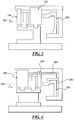
- FIG. 4 A further alternative embodiment of a composite clutch 220 is illustrated in FIG. 4 that incorporates a modified actuator assembly 260.
- the composite clutch 220 includes a friction clutch assembly 234 and a dog clutch assembly 236 that are substantially the same as the foregoing embodiments.
- the actuator assembly 260 includes a first piston 262 operatively coupled to the friction clutch assembly 234 and a second piston 264 operatively coupled to the dog clutch assembly 236.
- the first and second pistons 262, 264 are operable independent of one another, thereby eliminating the need for the spring 56 or a dog clutch that must slide to engage the friction clutch.
- the independently operable pistons 262, 264 allow greater control of the point at which the composite clutch 220 transitions from friction clutch mode to dog clutch mode. Furthermore, the transition point is no longer static but instead may be controlled to occur at different locations depending on operating parameters, thereby providing more flexible and precise control of the composite clutch 220.
- the foregoing provides a composite clutch that can advantageously be used in a vehicle or other transmission.
- the composite clutch includes friction and dog clutch assemblies to enable operation in friction and dog clutch modes.
- the combination provides a smooth shift feel, improved controllability at lower torques, a high static torque capacity, and a low drag torque, while packaging the device in the space currently allocated for conventional clutches and using the same actuator currently available for conventional friction clutches.
- the composite clutch may be coupled to either a simple hub or a one-way clutch, which permits the following operational modes: (1) Locked in one direction, freewheel in the opposite direction; (2) Low torque friction clutch in one direction; (3) Low torque friction clutch in both directions; and (4) Mechanical lock in both directions.
Landscapes
- Engineering & Computer Science (AREA)
- General Engineering & Computer Science (AREA)
- Mechanical Engineering (AREA)
- Hydraulic Clutches, Magnetic Clutches, Fluid Clutches, And Fluid Joints (AREA)
- Mechanical Operated Clutches (AREA)
Applications Claiming Priority (2)
| Application Number | Priority Date | Filing Date | Title |
|---|---|---|---|
| US4547708P | 2008-04-16 | 2008-04-16 | |
| PCT/US2009/040012 WO2009129113A2 (en) | 2008-04-16 | 2009-04-09 | Synchro-lock clutch - combination friction and mechanical locking clutch |
Publications (3)
| Publication Number | Publication Date |
|---|---|
| EP2274528A2 EP2274528A2 (en) | 2011-01-19 |
| EP2274528A4 EP2274528A4 (en) | 2017-08-23 |
| EP2274528B1 true EP2274528B1 (en) | 2020-07-15 |
Family
ID=41199654
Family Applications (1)
| Application Number | Title | Priority Date | Filing Date |
|---|---|---|---|
| EP09733289.4A Active EP2274528B1 (en) | 2008-04-16 | 2009-04-09 | Synchro-lock clutch combination friction and mechanical locking clutch |
Country Status (5)
| Country | Link |
|---|---|
| US (1) | US8905212B2 (zh) |
| EP (1) | EP2274528B1 (zh) |
| JP (1) | JP5789508B2 (zh) |
| CN (1) | CN101981336B (zh) |
| WO (1) | WO2009129113A2 (zh) |
Families Citing this family (29)
| Publication number | Priority date | Publication date | Assignee | Title |
|---|---|---|---|---|
| EP2274528B1 (en) | 2008-04-16 | 2020-07-15 | BorgWarner Inc. | Synchro-lock clutch combination friction and mechanical locking clutch |
| DE102010046961A1 (de) * | 2010-09-29 | 2012-03-29 | Daimler Ag | Getriebeschaltvorrichtung |
| US8584823B2 (en) | 2010-12-17 | 2013-11-19 | GM Global Technology Operations LLC | Torque transmitting assembly with dog clutch and plate clutch features |
| US9074662B2 (en) | 2012-04-04 | 2015-07-07 | Gm Global Technology Operations, Llc | Binary and friction clutch assembly |
| US9222549B2 (en) | 2012-04-04 | 2015-12-29 | Gm Global Technology Operations, Llc | Multi-speed transmission |
| US9011289B2 (en) * | 2012-12-14 | 2015-04-21 | Ford Global Technologies, Llc | Transmission clutch assembly |
| CA2904437C (en) | 2013-03-15 | 2021-01-05 | Allison Transmission, Inc. | Variator bypass clutch |
| JP5930121B2 (ja) * | 2013-04-16 | 2016-06-08 | トヨタ自動車株式会社 | 係合装置及び動力伝達装置 |
| US9267553B2 (en) | 2013-04-30 | 2016-02-23 | Avl Powertrain Engineering, Inc. | Transmission including dog clutch arrangement and method |
| US10060485B2 (en) | 2014-01-30 | 2018-08-28 | Borgwarner Inc. | Composite friction and dog clutch |
| WO2015120909A1 (en) * | 2014-02-14 | 2015-08-20 | Gkn Driveline International Gmbh | Coupling assembly and driveline assembly with such a coupling assembly |
| WO2016011096A1 (en) | 2014-07-16 | 2016-01-21 | Dana Automotives Systems Group, LLC | A drive unit with twin side shaft torque coupling |
| US9644726B2 (en) | 2014-11-11 | 2017-05-09 | Dana Heavy Vehicle Systems Group, Llc | Vehicle differential and method of operating the same |
| DE102014117194B4 (de) * | 2014-11-24 | 2016-10-06 | Hoerbiger Antriebstechnik Holding Gmbh | Schaltvorrichtung für ein Kraftfahrzeuggetriebe sowie Verfahren zur Ansteuerung eines Kraftfahrzeuggetriebes |
| DE102015203571A1 (de) * | 2015-02-27 | 2016-09-01 | Zf Friedrichshafen Ag | Kupplungsvorrichtung |
| JP6240109B2 (ja) * | 2015-03-02 | 2017-11-29 | トヨタ自動車株式会社 | 噛み合い式係合装置 |
| DE102015008834A1 (de) * | 2015-07-08 | 2017-01-12 | Daimler Ag | Getriebevorrichtung |
| US10378631B2 (en) | 2016-04-22 | 2019-08-13 | Borgwarner Inc. | Friction clutch having a first friction material engageable in a partially engaged position and a second friction material engageable in a fully engaged position |
| US10174794B2 (en) * | 2016-07-28 | 2019-01-08 | GM Global Technology Operations LLC | Power take-off assembly having a multiple stage clutch |
| US10197144B2 (en) | 2017-01-20 | 2019-02-05 | Dana Heavy Vehicle Systems Group, Llc | Drive unit with torque vectoring and an axle disconnect and reconnect mechanism |
| US10309522B2 (en) * | 2017-01-23 | 2019-06-04 | Borgwarner Inc. | Transfer case pump with multiple flow paths to internal components |
| US10190643B2 (en) * | 2017-02-16 | 2019-01-29 | GM Global Technology Operations LLC | Synchronizer for radially applied dog clutch for a vehicle |
| US20180335127A1 (en) * | 2017-05-17 | 2018-11-22 | Borgwarner Inc. | Pump for Torque Transfer Device |
| DE102017209398A1 (de) * | 2017-06-02 | 2018-12-06 | Zf Friedrichshafen Ag | Kupplungsanordnung sowie Antriebsstrangeinheit |
| CN109812512B (zh) * | 2019-02-18 | 2021-03-16 | 湖南农业大学 | 一种农用复合式离合器装置 |
| DE102019204294B4 (de) * | 2019-03-27 | 2022-10-20 | Vitesco Technologies Germany Gmbh | Verfahren zum Steuern einer Klauenkupplung sowie Anordnung, aufweisend ein Getriebe und einen Zahnradaktuator |
| DE102020007370A1 (de) | 2019-12-10 | 2021-06-10 | Borgwarner Inc. | Verfahren zum betrieb eines schaltsystems für ein fahrzeuggetriebe |
| DE102020129812A1 (de) * | 2019-12-10 | 2021-06-10 | Borgwarner Inc. | Schaltsystem mit Schaltanordnung und Verfahren zum Betreiben desselben |
| DE102020007372A1 (de) | 2019-12-10 | 2021-06-10 | Borgwarner Inc. | Schaltsystem für ein fahrzeuggetriebe und verfahren zu dessen betrieb |
Family Cites Families (29)
| Publication number | Priority date | Publication date | Assignee | Title |
|---|---|---|---|---|
| US3063529A (en) * | 1959-09-25 | 1962-11-13 | Clark Equipment Co | Locking clutch |
| US3300004A (en) * | 1964-02-27 | 1967-01-24 | Gen Motors Corp | Sequentially engaged clutches connected in series and cooling means therefor |
| US3252553A (en) * | 1964-03-24 | 1966-05-24 | Gen Motors Corp | Clutch and coupling |
| US3680409A (en) * | 1969-11-13 | 1972-08-01 | Alan Hawker Chamberlain | Reversible transmission with friction and positive clutches |
| US4349091A (en) * | 1980-11-12 | 1982-09-14 | Yanmar Diesel Engine Co., Ltd. | Synchronized dog clutch |
| WO1986002704A1 (fr) * | 1984-10-24 | 1986-05-09 | Zahnradfabrik Friedrichshafen Ag | Embrayage lamellaire avec embrayage a griffes |
| WO1987000595A1 (en) * | 1985-07-26 | 1987-01-29 | Zahnradfabrik Friedrichshafen Ag | Claw coupling with synchronization device for locking |
| JP2889956B2 (ja) * | 1990-08-30 | 1999-05-10 | 株式会社ダイナックス | 機械的一体化機構を具えた摩擦係合装置 |
| US5339936A (en) * | 1993-05-24 | 1994-08-23 | Eaton Corporation | Synchronizer pre-energizer spring system |
| US5735767A (en) * | 1996-10-21 | 1998-04-07 | New Venture Gear, Inc. | Add-on two-speed compounder |
| DE19822193B4 (de) * | 1998-05-16 | 2010-06-10 | Zf Friedrichshafen Ag | Lastschaltgetriebe |
| JP2002039224A (ja) * | 2000-07-31 | 2002-02-06 | Honda Motor Co Ltd | ワンウェイクラッチ |
| FR2817009B1 (fr) * | 2000-11-17 | 2003-01-24 | Antonov Automotive Europ | Dispositif de transmission, notamment pour vehicule terrestre |
| US20030089569A1 (en) * | 2000-11-17 | 2003-05-15 | Roumen Antonov | Trasmission devices, for ground vehicles and more particularly for molor-cars |
| US6996805B2 (en) * | 2001-06-28 | 2006-02-07 | Microsoft Corporation | Methods and systems of testing software, and methods and systems of modeling user behavior |
| US6889804B2 (en) * | 2001-06-29 | 2005-05-10 | Isuzu Motors Limited | Clutch control method |
| FR2833666B1 (fr) * | 2001-12-14 | 2004-02-27 | Thales Sa | Dispositif d'accouplement a crabot |
| US6736747B1 (en) * | 2002-01-23 | 2004-05-18 | Sonnax Industries, Inc. | Forward clutch control valve assembly |
| DE10211396A1 (de) * | 2002-03-15 | 2003-09-25 | Zf Lenksysteme Gmbh | Hilfskraftlenkung mit hydraulicher Hilfskraftunterstützung |
| US6852059B2 (en) * | 2003-01-03 | 2005-02-08 | General Motors Corporation | Six-speed dual-clutch transmissions having planetary gear sets with two interconnecting members |
| DE10331370A1 (de) * | 2003-07-11 | 2005-03-03 | Zf Friedrichshafen Ag | Automatgetriebe mit einem hydraulisch betätigbaren Schaltglied |
| US7086515B2 (en) * | 2003-08-19 | 2006-08-08 | Borgwarner Inc. | Clutch and synchronizer having permanent magnet actuators |
| US7349785B2 (en) * | 2004-03-31 | 2008-03-25 | General Motors Corporation | Method of controlling clutch slip during gear shifts of an automatic transmission |
| DE102004017123A1 (de) * | 2004-04-07 | 2005-10-27 | Zf Friedrichshafen Ag | Verrastbares Schaltelement in einem Automatgetriebe |
| US6966805B1 (en) | 2004-06-10 | 2005-11-22 | Brunswick Corporation | Marine transmission with synchronized engagement of a dog clutch |
| JP4412080B2 (ja) * | 2004-07-06 | 2010-02-10 | トヨタ自動車株式会社 | 自動変速機のクラッチ装置 |
| JP4619155B2 (ja) * | 2005-03-08 | 2011-01-26 | Nskワーナー株式会社 | 多板クラッチ |
| GB0526429D0 (en) * | 2005-12-23 | 2006-02-08 | Knowles Arthur | Drive engagement apparatus |
| EP2274528B1 (en) | 2008-04-16 | 2020-07-15 | BorgWarner Inc. | Synchro-lock clutch combination friction and mechanical locking clutch |
-
2009
- 2009-04-09 EP EP09733289.4A patent/EP2274528B1/en active Active
- 2009-04-09 JP JP2011505098A patent/JP5789508B2/ja active Active
- 2009-04-09 CN CN2009801099280A patent/CN101981336B/zh not_active Expired - Fee Related
- 2009-04-09 WO PCT/US2009/040012 patent/WO2009129113A2/en active Application Filing
- 2009-04-09 US US12/937,422 patent/US8905212B2/en active Active
Non-Patent Citations (1)
| Title |
|---|
| None * |
Also Published As
| Publication number | Publication date |
|---|---|
| US8905212B2 (en) | 2014-12-09 |
| CN101981336A (zh) | 2011-02-23 |
| WO2009129113A3 (en) | 2010-01-28 |
| JP2011518296A (ja) | 2011-06-23 |
| CN101981336B (zh) | 2013-08-21 |
| EP2274528A4 (en) | 2017-08-23 |
| JP5789508B2 (ja) | 2015-10-07 |
| EP2274528A2 (en) | 2011-01-19 |
| US20110155530A1 (en) | 2011-06-30 |
| WO2009129113A2 (en) | 2009-10-22 |
Similar Documents
| Publication | Publication Date | Title |
|---|---|---|
| EP2274528B1 (en) | Synchro-lock clutch combination friction and mechanical locking clutch | |
| US8678971B2 (en) | Drive assembly | |
| US8821334B2 (en) | High efficiency transfer case | |
| US8156837B2 (en) | Multiple-ratio transmission with concentric offset shift forks | |
| JP3111768B2 (ja) | 自動変速機の摩擦係合装置 | |
| US5788037A (en) | Integrated clutch transmission | |
| US6419068B1 (en) | Park gear damper for an automatic transmission for an automotive vehicle | |
| WO2002040900A3 (en) | Transmission devices, for ground vehicles and more particularly for motors-cars | |
| EP3099952B1 (en) | Composite friction and dog clutch | |
| JP5145185B2 (ja) | 動力伝達装置 | |
| US20080264746A1 (en) | Latching Linear Actuator | |
| US6406400B1 (en) | Integrated vehicle manual transmission and clutch with planetary gear arrangement | |
| KR20010015154A (ko) | 유성기어 변속기용 가역성 원웨이 클러치 | |
| US20180172086A1 (en) | Electronic clutch actuator with manual override piston | |
| US20180172085A1 (en) | System and method for clutch actuation having electronic clutch actuator with manual operation | |
| EP1753966B1 (en) | Clutch | |
| KR20220136802A (ko) | 차량의 차동제한장치 | |
| US11859696B2 (en) | Module for a system for synchronizing and driving a transmission gearbox countershaft | |
| US6981931B2 (en) | Method and apparatus for providing momentary torque reversal for a transmission having an automated shift system | |
| EP0742378A2 (en) | Clutch operating mechanism | |
| EP4283151A1 (en) | Force intensifying, multi-chambered clutch actuation system for power take-off | |
| US5016739A (en) | Friction clutch system | |
| JP2003278808A (ja) | 自動変速装置 | |
| JP3214744B2 (ja) | 車両の動力伝達装置 | |
| US20180172087A1 (en) | System and method for clutch actuation having electronic clutch actuator with integrated manual operation |
Legal Events
| Date | Code | Title | Description |
|---|---|---|---|
| PUAI | Public reference made under article 153(3) epc to a published international application that has entered the european phase |
Free format text: ORIGINAL CODE: 0009012 |
|
| 17P | Request for examination filed |
Effective date: 20101110 |
|
| AK | Designated contracting states |
Kind code of ref document: A2 Designated state(s): AT BE BG CH CY CZ DE DK EE ES FI FR GB GR HR HU IE IS IT LI LT LU LV MC MK MT NL NO PL PT RO SE SI SK TR |
|
| AX | Request for extension of the european patent |
Extension state: AL BA RS |
|
| DAX | Request for extension of the european patent (deleted) | ||
| A4 | Supplementary search report drawn up and despatched |
Effective date: 20170725 |
|
| RIC1 | Information provided on ipc code assigned before grant |
Ipc: F16D 11/14 20060101AFI20170719BHEP Ipc: F16D 11/04 20060101ALI20170719BHEP |
|
| STAA | Information on the status of an ep patent application or granted ep patent |
Free format text: STATUS: EXAMINATION IS IN PROGRESS |
|
| 17Q | First examination report despatched |
Effective date: 20180907 |
|
| GRAP | Despatch of communication of intention to grant a patent |
Free format text: ORIGINAL CODE: EPIDOSNIGR1 |
|
| STAA | Information on the status of an ep patent application or granted ep patent |
Free format text: STATUS: GRANT OF PATENT IS INTENDED |
|
| INTG | Intention to grant announced |
Effective date: 20200220 |
|
| GRAS | Grant fee paid |
Free format text: ORIGINAL CODE: EPIDOSNIGR3 |
|
| GRAA | (expected) grant |
Free format text: ORIGINAL CODE: 0009210 |
|
| STAA | Information on the status of an ep patent application or granted ep patent |
Free format text: STATUS: THE PATENT HAS BEEN GRANTED |
|
| RBV | Designated contracting states (corrected) |
Designated state(s): DE |
|
| AK | Designated contracting states |
Kind code of ref document: B1 Designated state(s): DE |
|
| RAP1 | Party data changed (applicant data changed or rights of an application transferred) |
Owner name: BORGWARNER INC. |
|
| REG | Reference to a national code |
Ref country code: DE Ref legal event code: R096 Ref document number: 602009062412 Country of ref document: DE |
|
| REG | Reference to a national code |
Ref country code: DE Ref legal event code: R097 Ref document number: 602009062412 Country of ref document: DE |
|
| PLBE | No opposition filed within time limit |
Free format text: ORIGINAL CODE: 0009261 |
|
| STAA | Information on the status of an ep patent application or granted ep patent |
Free format text: STATUS: NO OPPOSITION FILED WITHIN TIME LIMIT |
|
| 26N | No opposition filed |
Effective date: 20210416 |
|
| P01 | Opt-out of the competence of the unified patent court (upc) registered |
Effective date: 20230327 |
|
| PGFP | Annual fee paid to national office [announced via postgrant information from national office to epo] |
Ref country code: DE Payment date: 20230320 Year of fee payment: 15 |