EP2274525B1 - Bearings - Google Patents
Bearings Download PDFInfo
- Publication number
- EP2274525B1 EP2274525B1 EP09730264.0A EP09730264A EP2274525B1 EP 2274525 B1 EP2274525 B1 EP 2274525B1 EP 09730264 A EP09730264 A EP 09730264A EP 2274525 B1 EP2274525 B1 EP 2274525B1
- Authority
- EP
- European Patent Office
- Prior art keywords
- bearing
- ring
- cylinder
- outer ring
- flanged
- Prior art date
- Legal status (The legal status is an assumption and is not a legal conclusion. Google has not performed a legal analysis and makes no representation as to the accuracy of the status listed.)
- Not-in-force
Links
Images



Classifications
-
- F—MECHANICAL ENGINEERING; LIGHTING; HEATING; WEAPONS; BLASTING
- F16—ENGINEERING ELEMENTS AND UNITS; GENERAL MEASURES FOR PRODUCING AND MAINTAINING EFFECTIVE FUNCTIONING OF MACHINES OR INSTALLATIONS; THERMAL INSULATION IN GENERAL
- F16C—SHAFTS; FLEXIBLE SHAFTS; ELEMENTS OR CRANKSHAFT MECHANISMS; ROTARY BODIES OTHER THAN GEARING ELEMENTS; BEARINGS
- F16C33/00—Parts of bearings; Special methods for making bearings or parts thereof
- F16C33/02—Parts of sliding-contact bearings
- F16C33/04—Brasses; Bushes; Linings
- F16C33/06—Sliding surface mainly made of metal
- F16C33/10—Construction relative to lubrication
-
- C—CHEMISTRY; METALLURGY
- C10—PETROLEUM, GAS OR COKE INDUSTRIES; TECHNICAL GASES CONTAINING CARBON MONOXIDE; FUELS; LUBRICANTS; PEAT
- C10M—LUBRICATING COMPOSITIONS; USE OF CHEMICAL SUBSTANCES EITHER ALONE OR AS LUBRICATING INGREDIENTS IN A LUBRICATING COMPOSITION
- C10M119/00—Lubricating compositions characterised by the thickener being a macromolecular compound
- C10M119/02—Hydrocarbon polymers; Hydrocarbon polymers modified by oxidation
-
- C—CHEMISTRY; METALLURGY
- C10—PETROLEUM, GAS OR COKE INDUSTRIES; TECHNICAL GASES CONTAINING CARBON MONOXIDE; FUELS; LUBRICANTS; PEAT
- C10M—LUBRICATING COMPOSITIONS; USE OF CHEMICAL SUBSTANCES EITHER ALONE OR AS LUBRICATING INGREDIENTS IN A LUBRICATING COMPOSITION
- C10M169/00—Lubricating compositions characterised by containing as components a mixture of at least two types of ingredient selected from base-materials, thickeners or additives, covered by the preceding groups, each of these compounds being essential
- C10M169/02—Mixtures of base-materials and thickeners
-
- F—MECHANICAL ENGINEERING; LIGHTING; HEATING; WEAPONS; BLASTING
- F16—ENGINEERING ELEMENTS AND UNITS; GENERAL MEASURES FOR PRODUCING AND MAINTAINING EFFECTIVE FUNCTIONING OF MACHINES OR INSTALLATIONS; THERMAL INSULATION IN GENERAL
- F16C—SHAFTS; FLEXIBLE SHAFTS; ELEMENTS OR CRANKSHAFT MECHANISMS; ROTARY BODIES OTHER THAN GEARING ELEMENTS; BEARINGS
- F16C33/00—Parts of bearings; Special methods for making bearings or parts thereof
- F16C33/02—Parts of sliding-contact bearings
- F16C33/04—Brasses; Bushes; Linings
- F16C33/06—Sliding surface mainly made of metal
- F16C33/10—Construction relative to lubrication
- F16C33/102—Construction relative to lubrication with grease as lubricant
-
- C—CHEMISTRY; METALLURGY
- C10—PETROLEUM, GAS OR COKE INDUSTRIES; TECHNICAL GASES CONTAINING CARBON MONOXIDE; FUELS; LUBRICANTS; PEAT
- C10M—LUBRICATING COMPOSITIONS; USE OF CHEMICAL SUBSTANCES EITHER ALONE OR AS LUBRICATING INGREDIENTS IN A LUBRICATING COMPOSITION
- C10M2203/00—Organic non-macromolecular hydrocarbon compounds and hydrocarbon fractions as ingredients in lubricant compositions
- C10M2203/10—Petroleum or coal fractions, e.g. tars, solvents, bitumen
-
- C—CHEMISTRY; METALLURGY
- C10—PETROLEUM, GAS OR COKE INDUSTRIES; TECHNICAL GASES CONTAINING CARBON MONOXIDE; FUELS; LUBRICANTS; PEAT
- C10M—LUBRICATING COMPOSITIONS; USE OF CHEMICAL SUBSTANCES EITHER ALONE OR AS LUBRICATING INGREDIENTS IN A LUBRICATING COMPOSITION
- C10M2203/00—Organic non-macromolecular hydrocarbon compounds and hydrocarbon fractions as ingredients in lubricant compositions
- C10M2203/10—Petroleum or coal fractions, e.g. tars, solvents, bitumen
- C10M2203/102—Aliphatic fractions
-
- C—CHEMISTRY; METALLURGY
- C10—PETROLEUM, GAS OR COKE INDUSTRIES; TECHNICAL GASES CONTAINING CARBON MONOXIDE; FUELS; LUBRICANTS; PEAT
- C10M—LUBRICATING COMPOSITIONS; USE OF CHEMICAL SUBSTANCES EITHER ALONE OR AS LUBRICATING INGREDIENTS IN A LUBRICATING COMPOSITION
- C10M2203/00—Organic non-macromolecular hydrocarbon compounds and hydrocarbon fractions as ingredients in lubricant compositions
- C10M2203/10—Petroleum or coal fractions, e.g. tars, solvents, bitumen
- C10M2203/106—Naphthenic fractions
-
- C—CHEMISTRY; METALLURGY
- C10—PETROLEUM, GAS OR COKE INDUSTRIES; TECHNICAL GASES CONTAINING CARBON MONOXIDE; FUELS; LUBRICANTS; PEAT
- C10M—LUBRICATING COMPOSITIONS; USE OF CHEMICAL SUBSTANCES EITHER ALONE OR AS LUBRICATING INGREDIENTS IN A LUBRICATING COMPOSITION
- C10M2205/00—Organic macromolecular hydrocarbon compounds or fractions, whether or not modified by oxidation as ingredients in lubricant compositions
- C10M2205/02—Organic macromolecular hydrocarbon compounds or fractions, whether or not modified by oxidation as ingredients in lubricant compositions containing acyclic monomers
- C10M2205/028—Organic macromolecular hydrocarbon compounds or fractions, whether or not modified by oxidation as ingredients in lubricant compositions containing acyclic monomers containing aliphatic monomers having more than four carbon atoms
-
- C—CHEMISTRY; METALLURGY
- C10—PETROLEUM, GAS OR COKE INDUSTRIES; TECHNICAL GASES CONTAINING CARBON MONOXIDE; FUELS; LUBRICANTS; PEAT
- C10M—LUBRICATING COMPOSITIONS; USE OF CHEMICAL SUBSTANCES EITHER ALONE OR AS LUBRICATING INGREDIENTS IN A LUBRICATING COMPOSITION
- C10M2205/00—Organic macromolecular hydrocarbon compounds or fractions, whether or not modified by oxidation as ingredients in lubricant compositions
- C10M2205/02—Organic macromolecular hydrocarbon compounds or fractions, whether or not modified by oxidation as ingredients in lubricant compositions containing acyclic monomers
- C10M2205/028—Organic macromolecular hydrocarbon compounds or fractions, whether or not modified by oxidation as ingredients in lubricant compositions containing acyclic monomers containing aliphatic monomers having more than four carbon atoms
- C10M2205/0285—Organic macromolecular hydrocarbon compounds or fractions, whether or not modified by oxidation as ingredients in lubricant compositions containing acyclic monomers containing aliphatic monomers having more than four carbon atoms used as base material
-
- C—CHEMISTRY; METALLURGY
- C10—PETROLEUM, GAS OR COKE INDUSTRIES; TECHNICAL GASES CONTAINING CARBON MONOXIDE; FUELS; LUBRICANTS; PEAT
- C10M—LUBRICATING COMPOSITIONS; USE OF CHEMICAL SUBSTANCES EITHER ALONE OR AS LUBRICATING INGREDIENTS IN A LUBRICATING COMPOSITION
- C10M2205/00—Organic macromolecular hydrocarbon compounds or fractions, whether or not modified by oxidation as ingredients in lubricant compositions
- C10M2205/16—Paraffin waxes; Petrolatum, e.g. slack wax
- C10M2205/166—Paraffin waxes; Petrolatum, e.g. slack wax used as thickening agent
-
- C—CHEMISTRY; METALLURGY
- C10—PETROLEUM, GAS OR COKE INDUSTRIES; TECHNICAL GASES CONTAINING CARBON MONOXIDE; FUELS; LUBRICANTS; PEAT
- C10M—LUBRICATING COMPOSITIONS; USE OF CHEMICAL SUBSTANCES EITHER ALONE OR AS LUBRICATING INGREDIENTS IN A LUBRICATING COMPOSITION
- C10M2207/00—Organic non-macromolecular hydrocarbon compounds containing hydrogen, carbon and oxygen as ingredients in lubricant compositions
- C10M2207/02—Hydroxy compounds
- C10M2207/023—Hydroxy compounds having hydroxy groups bound to carbon atoms of six-membered aromatic rings
- C10M2207/026—Hydroxy compounds having hydroxy groups bound to carbon atoms of six-membered aromatic rings with tertiary alkyl groups
-
- C—CHEMISTRY; METALLURGY
- C10—PETROLEUM, GAS OR COKE INDUSTRIES; TECHNICAL GASES CONTAINING CARBON MONOXIDE; FUELS; LUBRICANTS; PEAT
- C10M—LUBRICATING COMPOSITIONS; USE OF CHEMICAL SUBSTANCES EITHER ALONE OR AS LUBRICATING INGREDIENTS IN A LUBRICATING COMPOSITION
- C10M2207/00—Organic non-macromolecular hydrocarbon compounds containing hydrogen, carbon and oxygen as ingredients in lubricant compositions
- C10M2207/28—Esters
- C10M2207/281—Esters of (cyclo)aliphatic monocarboxylic acids
-
- C—CHEMISTRY; METALLURGY
- C10—PETROLEUM, GAS OR COKE INDUSTRIES; TECHNICAL GASES CONTAINING CARBON MONOXIDE; FUELS; LUBRICANTS; PEAT
- C10M—LUBRICATING COMPOSITIONS; USE OF CHEMICAL SUBSTANCES EITHER ALONE OR AS LUBRICATING INGREDIENTS IN A LUBRICATING COMPOSITION
- C10M2207/00—Organic non-macromolecular hydrocarbon compounds containing hydrogen, carbon and oxygen as ingredients in lubricant compositions
- C10M2207/28—Esters
- C10M2207/285—Esters of aromatic polycarboxylic acids
-
- C—CHEMISTRY; METALLURGY
- C10—PETROLEUM, GAS OR COKE INDUSTRIES; TECHNICAL GASES CONTAINING CARBON MONOXIDE; FUELS; LUBRICANTS; PEAT
- C10M—LUBRICATING COMPOSITIONS; USE OF CHEMICAL SUBSTANCES EITHER ALONE OR AS LUBRICATING INGREDIENTS IN A LUBRICATING COMPOSITION
- C10M2219/00—Organic non-macromolecular compounds containing sulfur, selenium or tellurium as ingredients in lubricant compositions
-
- C—CHEMISTRY; METALLURGY
- C10—PETROLEUM, GAS OR COKE INDUSTRIES; TECHNICAL GASES CONTAINING CARBON MONOXIDE; FUELS; LUBRICANTS; PEAT
- C10N—INDEXING SCHEME ASSOCIATED WITH SUBCLASS C10M RELATING TO LUBRICATING COMPOSITIONS
- C10N2020/00—Specified physical or chemical properties or characteristics, i.e. function, of component of lubricating compositions
- C10N2020/01—Physico-chemical properties
- C10N2020/02—Viscosity; Viscosity index
-
- C—CHEMISTRY; METALLURGY
- C10—PETROLEUM, GAS OR COKE INDUSTRIES; TECHNICAL GASES CONTAINING CARBON MONOXIDE; FUELS; LUBRICANTS; PEAT
- C10N—INDEXING SCHEME ASSOCIATED WITH SUBCLASS C10M RELATING TO LUBRICATING COMPOSITIONS
- C10N2030/00—Specified physical or chemical properties which is improved by the additive characterising the lubricating composition, e.g. multifunctional additives
- C10N2030/10—Inhibition of oxidation, e.g. anti-oxidants
-
- C—CHEMISTRY; METALLURGY
- C10—PETROLEUM, GAS OR COKE INDUSTRIES; TECHNICAL GASES CONTAINING CARBON MONOXIDE; FUELS; LUBRICANTS; PEAT
- C10N—INDEXING SCHEME ASSOCIATED WITH SUBCLASS C10M RELATING TO LUBRICATING COMPOSITIONS
- C10N2030/00—Specified physical or chemical properties which is improved by the additive characterising the lubricating composition, e.g. multifunctional additives
- C10N2030/40—Low content or no content compositions
-
- C—CHEMISTRY; METALLURGY
- C10—PETROLEUM, GAS OR COKE INDUSTRIES; TECHNICAL GASES CONTAINING CARBON MONOXIDE; FUELS; LUBRICANTS; PEAT
- C10N—INDEXING SCHEME ASSOCIATED WITH SUBCLASS C10M RELATING TO LUBRICATING COMPOSITIONS
- C10N2040/00—Specified use or application for which the lubricating composition is intended
- C10N2040/02—Bearings
-
- C—CHEMISTRY; METALLURGY
- C10—PETROLEUM, GAS OR COKE INDUSTRIES; TECHNICAL GASES CONTAINING CARBON MONOXIDE; FUELS; LUBRICANTS; PEAT
- C10N—INDEXING SCHEME ASSOCIATED WITH SUBCLASS C10M RELATING TO LUBRICATING COMPOSITIONS
- C10N2040/00—Specified use or application for which the lubricating composition is intended
- C10N2040/14—Electric or magnetic purposes
-
- C—CHEMISTRY; METALLURGY
- C10—PETROLEUM, GAS OR COKE INDUSTRIES; TECHNICAL GASES CONTAINING CARBON MONOXIDE; FUELS; LUBRICANTS; PEAT
- C10N—INDEXING SCHEME ASSOCIATED WITH SUBCLASS C10M RELATING TO LUBRICATING COMPOSITIONS
- C10N2050/00—Form in which the lubricant is applied to the material being lubricated
- C10N2050/10—Form in which the lubricant is applied to the material being lubricated semi-solid; greasy
Definitions
- the invention relates to bearings and, in particular, to self-lubricating bearings.
- Bearings can provide convenient means for rotatably, pivotably or slidably fastening multiple members to one another in a low maintenance manner.
- Applications for bearings include those that have continuous rotational movement, such as journals for supporting a driven shaft.
- Bearings can also be used for applications that have repeated pivotal movement, such as automotive door hinges, door checks, brake and accelerator pedals. Additional applications include those that have repeated reciprocal movement, such as automotive shock absorbers and struts.
- Bearings can also be used in lighter duty applications, such as multiple bar linkages used in the automotive industry for trunk deck lid and hood hinges.
- Low maintenance bearings can include a variety of configurations, such as, for example, bushes or journal bearings, thrust bearings or washers, locating pads, valve port plates, and wearing components for a variety of mechanisms.
- An example of a low maintenance sliding bearing includes a metal support and a plastic layer.
- EP 0 570 625 A2 is concerned with a swivel bearing comprising a spherical body accommodated in a housing, wherein the spherical body is supported in the housing by a rubber interlayer of annular design.
- US 2 814 538 A is concerned with a combination radial and end-thrust bearing.
- US 4 260 205 A is concerned with a gas bearing for textile machine applications including a rotor having a bearing surface shaped to define a truncated conical bearing surface and a foil shell having a corresponding truncated conical shape.
- US 3 162 930 A is concerned with a method of making antifiriction bearings.
- GB 567 905 A is concerned with thrust bearings comprising a sleeve secured to a shaft and provided with an intermediate flange received in recesses in race-rings, held together by a cage.
- the invention features bearings as defined in claim 1.
- the bearings can be used in a variety of high speed applications including high speed motors.
- the bearings may provide reduced motor vibrations, which can result in quieter motor operation and increased motor life.
- the invention features a bearing as defined in claim 1 comprising an inner ring having a passageway configured to engage a shaft, the inner ring having an inner surface and an outer surface, wherein the inner surface is configured to form a space between the shaft and the inner surface when the shaft is engaged with the bearing; an outer ring disposed around at least a portion of the inner ring, the outer ring having an inner surface and an outer surface, the outer ring comprising a polymer and forming a bearing surface at an interface with the inner ring wherein the inner surface of the outer ring has a radius that is greater at the midline of the outer ring than at the lateral edges of the outer ring; and a hollow cylindrical ring surrounding and fixed to the outer ring wherein the inner ring is rotatable in relation to the hollow cylindrical ring.
- Embodiments may include one or more of the following features.
- the first member consists essentially of a metallic material.
- the bearing further includes a lubricant between the first member and the second member. At least one of the first member or the second member includes a cavity containing the lubricant.
- the second member further includes a polymer.
- the first member includes a groove extending along a circumferential portion of the first member, and the second member includes a feature configured to engage with the groove and prevent axial movement of the first and second members relative to each other.
- the bearing further includes a third member disposed around at least a portion of the second member, the third member including a metallic material.
- the third member includes at least one radially and inwardly bent portion capable of restricting axial movement of the first member.
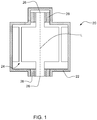
- a system 20 includes a housing 22, a motor 24 having a rotor 26, at least a portion of which is in the housing, and bearing 28 in the housing.
- Rotor 26 includes a shaft capable of rotating about its longitudinal axis L, and bearing 28 is positioned between the rotor and the housing.
- Bearing 28 is capable of reducing motor vibrations, which can result in quieter motor operation and increased motor life.
- bearing 28 is used to replace bushings and ball bearings in electric motors, e.g., high speed motors operating at approximately 1,000-6,000 RPM or more and under loads of approximately 0-300 pounds.
- bearing 28 includes an assembly of three parts: a first member (as shown, a cylinder 30), a second member (as shown, a first flanged cylinder 32) surrounding the first member, and a third member (as shown, a second flanged cylinder 34 although this member can also be an unflanged cylinder that surrounds double flanged cylinder 32) surrounding the second member.
- cylinder 30 is a solid and continuous member having an inner surface 36 and an outer surface. Inner surface 36 defines a passageway 38 that extends along the longitudinal axis L' of cylinder 30 (and bearing 28).
- passageway 38 The shape and size of passageway 38 are configured to allow cylinder 30 to be engaged with (e.g., pressed on to) rotor 26, resulting in an interference fit.
- cylinder 30 rotates along with the rotor as a result of the interference fit.
- the outer surface of cylinder 30 defines a cylindrical surface.
- Cylinder 30 can include (e.g., be formed of) any material including a metal, e.g., a pure metal (such as aluminum and magnesium) or an alloy (such as hardened steel), or a hard plastic. Cylinder 30 can be formed, for example, by machining, forming from a strip, and/or extrusion.
- First flanged cylinder 32 provides a bearing surface for cylinder 30 as cylinder 30 rotates during operation of motor 24. As shown, first flanged cylinder 32 extends along the length of cylinder 30 and surrounds at least a portion of the outer surface of cylinder 30. First flanged cylinder 32 has an inner surface and an outer surface, both of which define cylindrical surfaces. The inner surface of first flanged cylinder 32 is in circumferentially sliding engagement with the outer surface of cylinder 30. In some embodiments, the clearance between the inner surface of first flanged cylinder 32 and the outer surface of cylinder 30 is typically approximately 0.0005-0.003 inch (0.013-0.076 mm).
- first flanged cylinder 32 rotates along with rotor 26, but first flanged cylinder 32 remains stationary. Still referring to FIG. 2 , at a first end, first flanged cylinder 32 is flushed with an end of cylinder 30, and at an opposite second end, the first flanged cylinder includes a flange 40 configured to restrict axial movement of cylinder 30. As shown, flange 40 is a radially and inwardly bent portion that extends along the thickness of cylinder 30 but does not extend into passageway 38. The clearance between flange 40 and an end wall of cylinder 30 can be approximately 0.005-0.010 inch (0.127 ⁇ 0.254 mm).
- First flanged cylinder 32 can include (e.g., be formed of) any bearing material including a metal, e.g., a pure metal (such as aluminum and magnesium), an alloy (such as hardened steel), or a composite (e.g., Norglide Pro® material having a steel or aluminum substrate and a PTFE layer laminated to the substrate).
- a metal e.g., a pure metal (such as aluminum and magnesium), an alloy (such as hardened steel), or a composite (e.g., Norglide Pro® material having a steel or aluminum substrate and a PTFE layer laminated to the substrate).
- Other maintenance free bearing materials e.g. NORGLIDE® M, SM or T, can be used.
- First flanged cylinder 32 can be formed, for example, by rolling a strip of material and flanging the roll by conventional techniques.
- Second flanged cylinder 34 is configured to hold cylinder 30 and first flanged cylinder 32 within housing 22. As shown, second flanged cylinder 34 extends along the length of first flanged cylinder 32 and surrounds at least a portion of the outer surface of first flanged cylinder 32. First flanged cylinder 32 has an inner surface and an outer surface, both of which define cylindrical surfaces. At a first end, second flanged cylinder 34 is flush with an end of cylinder 30, and at a second opposite end, the second flanged cylinder includes a flange 42 configured to restrict axial movement of cylinder 30. The clearance between flange 42 and an end wall of cylinder 30 can be approximately 0 to 0.01 inch (0 ⁇ 0.254 mm).
- Second flanged cylinder 34 can include (e.g., be formed of) any hard material including a metal, e.g., a pure metal (such as aluminum and magnesium) or an alloy (such as hardened steel). Second flanged cylinder 34 can be formed, for example, by rolling a strip of material and flanging the roll by conventional techniques.
- Bearing 28 can be formed by forming the three parts described above (cylinder 30, first flanged cylinder 32, and second flanged cylinder 34) and assembling the parts together.
- cylinder 30 can be slid into first flanged cylinder 32, and these two parts can be slid into second flanged cylinder 34 to form bearing 28.
- Axial movement of cylinder 30 is restricted by first and second flanged cylinder 32, 34.
- bearing 28 can be placed in a housing or a space configured to receive the bearing, and a member (e.g., a shaft of a motor) can be placed in engagement with passageway 38 of the bearing.
- a member e.g., a shaft of a motor
- cylinder 30 of bearing 28 moves with the member and bears against first flanged cylinder 32.
- passageway 38 has having a circular cross section
- the passageway has a non-circular cross section, such as oval, elliptical, regularly or irregularly polygonal having three, four, five, six, seven, eight or more sides.
- the member e.g., rotating shaft
- the member configured to engage with passageway 38 would have a cross section with a correspondingly matching outer contour to provide the interference fit or engagement for operation, as described herein.
- first and/or second flanged cylinders 32, 34 include a slit or a gap extending parallel to longitudinal axis L'. After the parts of the bearing are assembled, the opposing parts of the slit can be joined together (e.g., by welding or by interlocking features) or remained spaced.
- cylinder 30 can include one or more grooves 50 extending wholly or partially about its outer circumferential surface, and first flanged cylinder 32 can include one or more complementary features 51 (e.g., a raised segment) configured to engage with the groove.
- first flanged cylinder 32 and the inner surface of second flanged cylinder 34 can include similar complementary features to prevent axial movement of these parts.
- the bearings described herein are used in applications in which a pivotable member (e.g., a shaft) is placed in the passageway of the bearings.
- a pivotable member e.g., a shaft
- the bearings described herein include one or more lubricants or lubricious layers between cylinder 30 and first flanged cylinder 32.
- the lubricant or lubricious layer can enhance the wear resistance of the bearings.
- materials included in the lubricant or lubricious layer include solid state materials (e.g., inorganic materials such as graphite and/or molybdenum disulfide), viscous fluids (e.g., grease), polymers (e.g., fluoropolymers (such as PTFE) and/or silicone), and combinations thereof.
- the outer surface of cylinder 30 and/or the inner surface of first flanged cylinder 32 can include one or more cavities 54 (e.g., pockets and/or grooves) that serve as reservoirs for the lubricant.
- One or more additives can be included in the lubricant or lubricious layer, for example, to enhance thermal conductivity and to dissipate heat that can be generated during use.
- An example of an additive is metal particles, e.g., bronze particles.
- the bearing members can include one or more intermediate layers between metallic and polymer layers.
- the intermediate layer can, for example, enhance adhesion or bonding of the polymer to the metallic substrate.
- the intermediate layer can include, for example, an adhesive such as fluoropolymers including PFA, MFA, ETFE, FEP, PCTFE, and PVDF, curing adhesives such as epoxy, polyimide adhesives, and lower temperature hot melts such as ethylene vinylacetate (EVA) and polyether/polyamide copolymer (Pebax®).
- FIG. 6 shows an exemplary two-component bearing 28' including a first member (as shown, cylinder 30) and a second member (as shown, first flanged cylinder 32') surrounding the first member.
- first flanged cylinder 32' includes a first flange 40' and a second flange 40" configured to restrict axial movement of cylinder 30.
- Flanged cylinder 32' may be a split cylinder that includes two ends that may be joined, for example, by welding, by adhesive bonding, with a connector, or through interlocking tabs and slots.
- bearing 28' can include one or more of the features described above (e.g., different cross-sectional shapes, lubricants, additional layers, grooves).
- Bearing 28' may optionally include a third component that surrounds the circumference of double flanged cylinder 32'. This third component may be void of flanges and may help to stabilize the bearing and keep it in round.
- the third component may be metallic and/or polymeric and may be shaped and sized to fit a specific housing or other application. It may be cylindrical or other shape such as a regular polygon.
- the inner surface of the third component may present a different shape than the outer surface. It may be friction fit or adhered to flanged cylinder 32'.
- FIG. 7 shows a bearing 28" including a first member (as shown, cylinder 30), a two-component second member (as shown, first flanged cylinder 32") surrounding the first member, and a third member (as shown, cylinder 50) surrounding the second member.
- Flanged cylinder 32" includes two parts 33, 33' that, respectively, have flanges 35, 35' configured to restrict axial movement of cylinder 30.
- Parts 33, 33' may be in axial contact with each other or may be axially spaced from each other to define a gap 52, for example, approximately 0.002 inch (0.05 mm) to approximately 0.010 inch (0.254 mm) long.
- cylinder 50 is a continuous cylinder with no flanges and can be formed of, for example, steel or aluminum. It is believed that cylinder 50 provides bearing 28" with stiffness and consistent clearances between the components of the bearing. The materials used to fabricate bearing 28", as well as the clearances between the components, can be the same as described above for bearing 28.
- Bearing 28" can include one or more of the features described above (e.g., different cross-sectional shapes, lubricants, additional layers, grooves).
- FIG. 8 shows a bearing 28'" including first member cylinder 30, first flanged cylinder 32" (second member) surrounding the first member, and cylinder 50 surrounding the second member.
- First flanged cylinder 32" includes two symmetrical halves 33 and 33'.
- first flanged cylinder 32" includes a metal substrate 59 and a polymer layer 60 on the metal substrate.
- first flanged cylinder 32" examples include a metal substrate (e.g., a steel or aluminum substrate) and a polymer layer (e.g., a PTFE layer) laminated to the substrate (e.g. NORGLIDE® M, SM T, Pro®).
- bearing 28'" includes a lubricant between cylinder 30 and first flanged cylinder 32", and as shown the first flanged cylinder includes a cavity 62 in polymer layer 60 near gap 52 to help retain the lubricant. Cavity 62 in polymer layer 60 may be present with or without gap 52.
- an appropriate lubricant is a lubricant composition including (by volume) 62% Mobil 1® 0W-40 motor oil, 19% Bakoda® ski wax and 19% Lucas® Heavy Duty Oil Stabilizer. Examples of additional lubricants are described in the patent application titled BEARING GREASE COMPOSITION, Attorney Docket No. O-5056, filed on even date herewith and which is hereby incorporated by reference herein. In other embodiments, bearing 28'" does not include the lubricant and/or cavity 62.
- An exemplary bearing having more than three components can include a first member (e.g., cylinder 30), a second member (e.g., first flanged cylinder 32) surrounding the first member, a third member (e.g., second flanged cylinder 34) surrounding the second member, and additional members (e.g., one, two, three or more) surrounding the third member.
- the additional members can surround the more radially inward members similarly to how the second member or the third member surrounds more radially inward member(s).
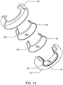
- FIGS. 9-11 show an assembled bearing 88 in an isometric view ( FIG. 9 ), in cutaway exploded view ( FIG. 10 ) and in cross-sectional view ( FIG. 11 ).
- the cylindrical members may be in the form of V-shaped (cross-sectional profile) rings.
- This embodiment includes inner V-shaped ring 36 which can slidably rotate with respect to outer V-shaped ring 38.
- Outer V-shaped ring 38 may be permanently fixed to hollow cylindrical ring 80.
- the inner and outer rings may include different profiles that are not specifically V-shaped.
- the cross-sectional profile of the inner ring may be U-shaped.
- This profile can allow for a concave outer surface (of the inner ring) structure that results in one or more substantial bearing surfaces that are not parallel to the radial axis of the bearing. This is in contrast, for example, to the bearing shown in FIG. 7 in which the majority of the bearing surface is parallel to the radial axis of the bearing.
- the radius of the inner ring and/or outer ring may be greater toward the center (midline) of the bearing than it is at the lateral edges of the bearing. Moving from the outer edge to the center of the bearing, the radius may increase linearly, as in the case of a V-shaped inner ring or according to the equation of a curve in the case of a U-shaped ring.
- inner ring 36 may be formed so that it fills space 89 while maintaining a V-shaped profile on the outer surface.
- the inner surface of the inner ring may be parallel to the radial axis of the bearing while the outer surface is not parallel to the radial axis of the bearing.
- Inner V-shaped ring 36 may be formed from a single piece or from multiple components as shown in FIG. 10 . If a multi-component inner V-shaped ring is chosen, the components may remain separate or may be permanently attached together. For example, complementary halves may be joined together at central line 96 to form a unitary inner V-shaped ring.
- the inner V-shaped ring may be, for example, metallic or a metallic alloy and may include, for instance, steel or bronze.
- inner V-shaped ring 36 may include two substantially straight inner surfaces (in cross section) 36a and 36b that form a "V" by sloping outwardly as they meet centrally in the bearing.
- Inner V-shaped ring 36 may include a flattened portion 36d at one or both of the outer edges of the ring.
- flattened portion 36d may be the only portion of inner V-shaped ring 36 that is in contact with the shaft.
- shaft 90 when shaft 90 is installed it may be supported by flattened portion 36d and forms a space 89 between the surface of the shaft and the V portion of the inner surface 36a and 36b of the inner V-shaped ring. Space 89 can reduce heat transfer between the bearing and the shaft which can, for example, result in a cooler operating motor.
- Inner surface 38A of outer V-shaped ring 38 may be complementary to outer surface 36c of inner V-shaped ring 36.
- Outer V-shaped ring 38 may include outer flattened portions that correspond to flattened portions 36d of inner V-shaped ring 36.
- Outer V-shaped ring 38 can be a composite and may include a fluoropolymer or other self-lubricating material on inner surface 38a that is laminated to a metallic substrate to form the composite ring.
- outer V-shaped ring 38 may be formed from NORGLIDE® M, SM, T, or Pro® as described above.
- Outer V-shaped ring 38 may be a single piece or may include two or more pieces joined together. In one embodiment, as shown, two symmetrical halves can be spot welded together. By spot welding, the joint between the two halves may form intermittent passages that allow lubricant to pass from cavity 87 to the bearing surfaces between the inner and outer V-shaped rings. In other cases the seam between the two halves may be completely sealed.
- Hollow cylindrical ring 80 may form a housing for bearing 88.
- Hollow cylindrical ring 80 may be formed from a metallic material such as steel.
- Hollow cylindrical ring 80 can include two L-shaped (in cross-section) cylindrical rings that may be joined together by, for example, welding, press fitting or overmolding with a polymer.
- laser spot weld 84 can be seen in FIG. 9 .
- Outer V-shaped ring 38 can be fixed to hollow cylindrical ring 80 by spot welding or other techniques. Spot welds 86a, 86b and 86c are evident in FIG. 9 and serve to affix hollow cylindrical ring 80 to outer V-shaped ring 38, thus immobilizing hollow cylindrical ring 80 with respect to outer V-shaped ring 38.
- inner V-shaped ring 36 is slidably rotatable in relation to both outer V-shaped ring 38 and hollow cylindrical ring 80.
- Hollow cylindrical ring 80 can be dimensioned to form cavity 87 that is a substantially toroidal shape and that extends around the outer surface 38b of outer V-shaped ring 38. "Substantially toroidal" means that the cavity extends 360 degrees around the bearing but (as shown) it need not have a circular or even a rounded cross-section. Inclusion of this cavity has been found to reduce vibration and provide quieter operation as well as provide greater tolerance regarding the angle of the shaft that is supported by bearing 88.
- cavity 87 may be extended by enlarging the axial walls 92 of hollow cylindrical ring 80.
- Cavity 87 may be empty or may contain an additional component such as a lubricant or damping material.
- cavity 87 may be filled, at least partially, with one of the greases or other lubricants described or referred to herein.
- the lubricant can be passively supplied to the bearing surfaces through passages formed in outer V-shaped bearing 38.
- Hollow cylindrical ring 80 may be coated partially or totally with an elastomer to produce an elastomer coated metal.
- an elastomeric coating may be applied to axial surface 92 or to cylindrical surface 94, or to both.
- the elastomeric coating can help to provide additional vibration and noise reduction as well as provide for easier and more secure fitting of the bearing in a device.
- Appropriate coatings may include, for example, natural and synthetic elastomers such as PVC, PVB and NBR (nitrile rubber).
- bearing 88 When used to rotatably support a shaft, such as a shaft of a motor or a steering mechanism, bearing 88 may be particularly tolerant of thrust loading that may cause extensive wear in alternative bearings. If an axial force is applied to the bearing through the shaft, this axial force is spread across substantially one half (the outer half) of the total contacting surfaces of the V-shaped bearing. In flanged bearings that include a substantially flat portion (in cross-section) from flange to flange, the force from the thrust loading may be applied almost entirely to the flange, resulting in excessive friction and wear at the flange location. It has been found that by spreading this force across the outer half of the V-shaped surface, rather than entirely to the flange, the frictional wear can be significantly reduced.
Landscapes
- Chemical & Material Sciences (AREA)
- General Engineering & Computer Science (AREA)
- Engineering & Computer Science (AREA)
- Oil, Petroleum & Natural Gas (AREA)
- Organic Chemistry (AREA)
- General Chemical & Material Sciences (AREA)
- Chemical Kinetics & Catalysis (AREA)
- Mechanical Engineering (AREA)
- Sliding-Contact Bearings (AREA)
- Lubricants (AREA)
- Support Of The Bearing (AREA)
- Rolling Contact Bearings (AREA)
- Vehicle Body Suspensions (AREA)
Description
- The invention relates to bearings and, in particular, to self-lubricating bearings.
- Bearings can provide convenient means for rotatably, pivotably or slidably fastening multiple members to one another in a low maintenance manner. Applications for bearings include those that have continuous rotational movement, such as journals for supporting a driven shaft. Bearings can also be used for applications that have repeated pivotal movement, such as automotive door hinges, door checks, brake and accelerator pedals. Additional applications include those that have repeated reciprocal movement, such as automotive shock absorbers and struts. Bearings can also be used in lighter duty applications, such as multiple bar linkages used in the automotive industry for trunk deck lid and hood hinges. Low maintenance bearings can include a variety of configurations, such as, for example, bushes or journal bearings, thrust bearings or washers, locating pads, valve port plates, and wearing components for a variety of mechanisms. An example of a low maintenance sliding bearing includes a metal support and a plastic layer.
EP 0 570 625 A2 is concerned with a swivel bearing comprising a spherical body accommodated in a housing, wherein the spherical body is supported in the housing by a rubber interlayer of annular design.US 2 814 538 A is concerned with a combination radial and end-thrust bearing.US 4 260 205 A is concerned with a gas bearing for textile machine applications including a rotor having a bearing surface shaped to define a truncated conical bearing surface and a foil shell having a corresponding truncated conical shape.US 3 162 930 A is concerned with a method of making antifiriction bearings.GB 567 905 A - The invention features bearings as defined in claim 1. The bearings can be used in a variety of high speed applications including high speed motors. The bearings may provide reduced motor vibrations, which can result in quieter motor operation and increased motor life.
- The invention features a bearing as defined in claim 1 comprising an inner ring having a passageway configured to engage a shaft, the inner ring having an inner surface and an outer surface, wherein the inner surface is configured to form a space between the shaft and the inner surface when the shaft is engaged with the bearing; an outer ring disposed around at least a portion of the inner ring, the outer ring having an inner surface and an outer surface, the outer ring comprising a polymer and forming a bearing surface at an interface with the inner ring wherein the inner surface of the outer ring has a radius that is greater at the midline of the outer ring than at the lateral edges of the outer ring; and a hollow cylindrical ring surrounding and fixed to the outer ring wherein the inner ring is rotatable in relation to the hollow cylindrical ring.
- Embodiments may include one or more of the following features. The first member consists essentially of a metallic material. The bearing further includes a lubricant between the first member and the second member. At least one of the first member or the second member includes a cavity containing the lubricant. The second member further includes a polymer. The first member includes a groove extending along a circumferential portion of the first member, and the second member includes a feature configured to engage with the groove and prevent axial movement of the first and second members relative to each other. The bearing further includes a third member disposed around at least a portion of the second member, the third member including a metallic material. The third member includes at least one radially and inwardly bent portion capable of restricting axial movement of the first member.
- Other aspects, features and advantages will be apparent from the description of the embodiments thereof and from the claims.
-
-
FIG. 1 is a schematic diagram of a system including a motor and a bearing. -
FIG. 2 is a perspective view of an embodiment of a bearing. -
FIG. 3 is a perspective, cut-away view of the bearing shown inFIG. 2 . -
FIG. 4 is a perspective view of a portion of an embodiment of a bearing. -
FIG. 5 is a perspective view of a portion of an embodiment of a bearing. -
FIG. 6 is a perspective, cut-away view of an embodiment of a bearing. -
FIG. 7 is a perspective, cut-away view of an embodiment of a bearing. -
FIG. 8 is a detailed, cross-sectional view of an embodiment of a bearing according to the invention. -
FIG. 9 is an isometric view of an embodiment of a bearing. -
FIG. 10 is a cutaway exploded view of the embodiment shown inFIG. 9 . -
FIG. 11 is a cross-sectional diagram of the embodiment shown inFIG. 9 . - Referring to
FIG. 1 , asystem 20 includes ahousing 22, amotor 24 having arotor 26, at least a portion of which is in the housing, and bearing 28 in the housing.Rotor 26 includes a shaft capable of rotating about its longitudinal axis L, andbearing 28 is positioned between the rotor and the housing.Bearing 28 is capable of reducing motor vibrations, which can result in quieter motor operation and increased motor life. In some embodiments,bearing 28 is used to replace bushings and ball bearings in electric motors, e.g., high speed motors operating at approximately 1,000-6,000 RPM or more and under loads of approximately 0-300 pounds. - As shown in
FIGS. 2 and 3 ,bearing 28 includes an assembly of three parts: a first member (as shown, a cylinder 30), a second member (as shown, a first flanged cylinder 32) surrounding the first member, and a third member (as shown, a second flangedcylinder 34 although this member can also be an unflanged cylinder that surrounds double flanged cylinder 32) surrounding the second member. As shown,cylinder 30 is a solid and continuous member having aninner surface 36 and an outer surface.Inner surface 36 defines apassageway 38 that extends along the longitudinal axis L' of cylinder 30 (and bearing 28). The shape and size ofpassageway 38 are configured to allowcylinder 30 to be engaged with (e.g., pressed on to)rotor 26, resulting in an interference fit. During operation ofmotor 24, asrotor 26 rotates about its longitudinal axis L,cylinder 30 rotates along with the rotor as a result of the interference fit. The outer surface ofcylinder 30 defines a cylindrical surface.Cylinder 30 can include (e.g., be formed of) any material including a metal, e.g., a pure metal (such as aluminum and magnesium) or an alloy (such as hardened steel), or a hard plastic.Cylinder 30 can be formed, for example, by machining, forming from a strip, and/or extrusion. - First flanged
cylinder 32 provides a bearing surface forcylinder 30 ascylinder 30 rotates during operation ofmotor 24. As shown, first flangedcylinder 32 extends along the length ofcylinder 30 and surrounds at least a portion of the outer surface ofcylinder 30. First flangedcylinder 32 has an inner surface and an outer surface, both of which define cylindrical surfaces. The inner surface of first flangedcylinder 32 is in circumferentially sliding engagement with the outer surface ofcylinder 30. In some embodiments, the clearance between the inner surface of first flangedcylinder 32 and the outer surface ofcylinder 30 is typically approximately 0.0005-0.003 inch (0.013-0.076 mm). As a result, during operation ofmotor 24,cylinder 30 rotates along withrotor 26, but first flangedcylinder 32 remains stationary. Still referring toFIG. 2 , at a first end, first flangedcylinder 32 is flushed with an end ofcylinder 30, and at an opposite second end, the first flanged cylinder includes aflange 40 configured to restrict axial movement ofcylinder 30. As shown,flange 40 is a radially and inwardly bent portion that extends along the thickness ofcylinder 30 but does not extend intopassageway 38. The clearance betweenflange 40 and an end wall ofcylinder 30 can be approximately 0.005-0.010 inch (0.127∼0.254 mm). First flangedcylinder 32 can include (e.g., be formed of) any bearing material including a metal, e.g., a pure metal (such as aluminum and magnesium), an alloy (such as hardened steel), or a composite (e.g., Norglide Pro® material having a steel or aluminum substrate and a PTFE layer laminated to the substrate). Other maintenance free bearing materials, e.g. NORGLIDE® M, SM or T, can be used. Firstflanged cylinder 32 can be formed, for example, by rolling a strip of material and flanging the roll by conventional techniques. - Second
flanged cylinder 34 is configured to holdcylinder 30 and firstflanged cylinder 32 withinhousing 22. As shown, secondflanged cylinder 34 extends along the length of firstflanged cylinder 32 and surrounds at least a portion of the outer surface of firstflanged cylinder 32. Firstflanged cylinder 32 has an inner surface and an outer surface, both of which define cylindrical surfaces. At a first end, secondflanged cylinder 34 is flush with an end ofcylinder 30, and at a second opposite end, the second flanged cylinder includes aflange 42 configured to restrict axial movement ofcylinder 30. The clearance betweenflange 42 and an end wall ofcylinder 30 can be approximately 0 to 0.01 inch (0∼0.254 mm). As shown,flange 42 is a radially and inwardly bent portion that extends along the thickness of firstflanged cylinder 32 andcylinder 30 but does not extend intopassageway 38. Secondflanged cylinder 34 can include (e.g., be formed of) any hard material including a metal, e.g., a pure metal (such as aluminum and magnesium) or an alloy (such as hardened steel). Secondflanged cylinder 34 can be formed, for example, by rolling a strip of material and flanging the roll by conventional techniques. -
Bearing 28 can be formed by forming the three parts described above (cylinder 30, firstflanged cylinder 32, and second flanged cylinder 34) and assembling the parts together. For example,cylinder 30 can be slid into firstflanged cylinder 32, and these two parts can be slid into secondflanged cylinder 34 to formbearing 28. Axial movement ofcylinder 30 is restricted by first and secondflanged cylinder - In use, bearing 28 can be placed in a housing or a space configured to receive the bearing, and a member (e.g., a shaft of a motor) can be placed in engagement with
passageway 38 of the bearing. When the member moves (e.g., rotates),cylinder 30 of bearing 28 moves with the member and bears against firstflanged cylinder 32. - While a number of embodiments have been described, the invention is not so limited.
- For example, while
passageway 38 is shown above has having a circular cross section, in other embodiments, the passageway has a non-circular cross section, such as oval, elliptical, regularly or irregularly polygonal having three, four, five, six, seven, eight or more sides. The member (e.g., rotating shaft) configured to engage withpassageway 38 would have a cross section with a correspondingly matching outer contour to provide the interference fit or engagement for operation, as described herein. - As another example, in some embodiments, the wall(s) of first and/or second
flanged cylinders - Referring to
FIG. 4 , to further reduce axial movement of the parts,cylinder 30 can include one ormore grooves 50 extending wholly or partially about its outer circumferential surface, and firstflanged cylinder 32 can include one or more complementary features 51 (e.g., a raised segment) configured to engage with the groove. Similarly, the outer surface of firstflanged cylinder 32 and the inner surface of secondflanged cylinder 34 can include similar complementary features to prevent axial movement of these parts. - In some embodiments, the bearings described herein are used in applications in which a pivotable member (e.g., a shaft) is placed in the passageway of the bearings.
- In some embodiments, the bearings described herein include one or more lubricants or lubricious layers between
cylinder 30 and firstflanged cylinder 32. The lubricant or lubricious layer can enhance the wear resistance of the bearings. Examples of materials included in the lubricant or lubricious layer include solid state materials (e.g., inorganic materials such as graphite and/or molybdenum disulfide), viscous fluids (e.g., grease), polymers (e.g., fluoropolymers (such as PTFE) and/or silicone), and combinations thereof. Referring toFIG. 5 , the outer surface ofcylinder 30 and/or the inner surface of firstflanged cylinder 32 can include one or more cavities 54 (e.g., pockets and/or grooves) that serve as reservoirs for the lubricant. - One or more additives can be included in the lubricant or lubricious layer, for example, to enhance thermal conductivity and to dissipate heat that can be generated during use. An example of an additive is metal particles, e.g., bronze particles.
- The bearing members can include one or more intermediate layers between metallic and polymer layers. The intermediate layer can, for example, enhance adhesion or bonding of the polymer to the metallic substrate. The intermediate layer can include, for example, an adhesive such as fluoropolymers including PFA, MFA, ETFE, FEP, PCTFE, and PVDF, curing adhesives such as epoxy, polyimide adhesives, and lower temperature hot melts such as ethylene vinylacetate (EVA) and polyether/polyamide copolymer (Pebax®).
- While bearing 28 as shown in
FIGS. 2 and 3 includes three components, in other embodiments, the bearing includes two components or more than three components.FIG. 6 shows an exemplary two-component bearing 28' including a first member (as shown, cylinder 30) and a second member (as shown, first flanged cylinder 32') surrounding the first member. At its ends, first flanged cylinder 32' includes a first flange 40' and asecond flange 40" configured to restrict axial movement ofcylinder 30. Flanged cylinder 32' may be a split cylinder that includes two ends that may be joined, for example, by welding, by adhesive bonding, with a connector, or through interlocking tabs and slots. The materials used to fabricate bearing 28', as well as the clearances between the components, can be the same as described above for bearing 28. Bearing 28' can include one or more of the features described above (e.g., different cross-sectional shapes, lubricants, additional layers, grooves). Bearing 28' may optionally include a third component that surrounds the circumference of double flanged cylinder 32'. This third component may be void of flanges and may help to stabilize the bearing and keep it in round. The third component may be metallic and/or polymeric and may be shaped and sized to fit a specific housing or other application. It may be cylindrical or other shape such as a regular polygon. The inner surface of the third component may present a different shape than the outer surface. It may be friction fit or adhered to flanged cylinder 32'. - As another example,
FIG. 7 shows abearing 28" including a first member (as shown, cylinder 30), a two-component second member (as shown, firstflanged cylinder 32") surrounding the first member, and a third member (as shown, cylinder 50) surrounding the second member.Flanged cylinder 32" includes twoparts flanges 35, 35' configured to restrict axial movement ofcylinder 30.Parts gap 52, for example, approximately 0.002 inch (0.05 mm) to approximately 0.010 inch (0.254 mm) long. As shown,cylinder 50 is a continuous cylinder with no flanges and can be formed of, for example, steel or aluminum. It is believed thatcylinder 50 providesbearing 28" with stiffness and consistent clearances between the components of the bearing. The materials used to fabricate bearing 28", as well as the clearances between the components, can be the same as described above for bearing 28. -
Bearing 28" can include one or more of the features described above (e.g., different cross-sectional shapes, lubricants, additional layers, grooves). For example,FIG. 8 shows a bearing 28'" includingfirst member cylinder 30, firstflanged cylinder 32" (second member) surrounding the first member, andcylinder 50 surrounding the second member. Firstflanged cylinder 32" includes twosymmetrical halves flanged cylinder 32" includes ametal substrate 59 and apolymer layer 60 on the metal substrate. Examples of materials for firstflanged cylinder 32" include a metal substrate (e.g., a steel or aluminum substrate) and a polymer layer (e.g., a PTFE layer) laminated to the substrate (e.g. NORGLIDE® M, SM T, Pro®). In some embodiments, bearing 28'" includes a lubricant betweencylinder 30 and firstflanged cylinder 32", and as shown the first flanged cylinder includes acavity 62 inpolymer layer 60 neargap 52 to help retain the lubricant.Cavity 62 inpolymer layer 60 may be present with or withoutgap 52. One specific example of an appropriate lubricant is a lubricant composition including (by volume) 62% Mobil 1® 0W-40 motor oil, 19% Bakoda® ski wax and 19% Lucas® Heavy Duty Oil Stabilizer. Examples of additional lubricants are described in the patent application titled BEARING GREASE COMPOSITION, Attorney Docket No. O-5056, filed on even date herewith and which is hereby incorporated by reference herein. In other embodiments, bearing 28'" does not include the lubricant and/orcavity 62. - Other embodiments may include four or more components. An exemplary bearing having more than three components can include a first member (e.g., cylinder 30), a second member (e.g., first flanged cylinder 32) surrounding the first member, a third member (e.g., second flanged cylinder 34) surrounding the second member, and additional members (e.g., one, two, three or more) surrounding the third member. The additional members can surround the more radially inward members similarly to how the second member or the third member surrounds more radially inward member(s).
- An example according to the invention is provided in
FIGS. 9-11 which show an assembledbearing 88 in an isometric view (FIG. 9 ), in cutaway exploded view (FIG. 10 ) and in cross-sectional view (FIG. 11 ). In this embodiment the cylindrical members may be in the form of V-shaped (cross-sectional profile) rings. This embodiment includes inner V-shapedring 36 which can slidably rotate with respect to outer V-shapedring 38. Outer V-shapedring 38 may be permanently fixed to hollowcylindrical ring 80. In similar embodiments the inner and outer rings may include different profiles that are not specifically V-shaped. For example, the cross-sectional profile of the inner ring may be U-shaped. This profile can allow for a concave outer surface (of the inner ring) structure that results in one or more substantial bearing surfaces that are not parallel to the radial axis of the bearing. This is in contrast, for example, to the bearing shown inFIG. 7 in which the majority of the bearing surface is parallel to the radial axis of the bearing. The radius of the inner ring and/or outer ring may be greater toward the center (midline) of the bearing than it is at the lateral edges of the bearing. Moving from the outer edge to the center of the bearing, the radius may increase linearly, as in the case of a V-shaped inner ring or according to the equation of a curve in the case of a U-shaped ring. In some cases it may be only the outer surface ofinner ring 36 and the inner surface ofouter ring 38 that exhibit this increasing radius. For example,inner ring 36 may be formed so that it fillsspace 89 while maintaining a V-shaped profile on the outer surface. In this case, the inner surface of the inner ring may be parallel to the radial axis of the bearing while the outer surface is not parallel to the radial axis of the bearing. - Inner V-shaped
ring 36 may be formed from a single piece or from multiple components as shown inFIG. 10 . If a multi-component inner V-shaped ring is chosen, the components may remain separate or may be permanently attached together. For example, complementary halves may be joined together atcentral line 96 to form a unitary inner V-shaped ring. The inner V-shaped ring may be, for example, metallic or a metallic alloy and may include, for instance, steel or bronze. As seen inFIGS. 10 and11 , inner V-shapedring 36 may include two substantially straight inner surfaces (in cross section) 36a and 36b that form a "V" by sloping outwardly as they meet centrally in the bearing. Inner V-shapedring 36 may include a flattenedportion 36d at one or both of the outer edges of the ring. When inner V-shapedring 36 receives a shaft 90 (shown in dotted lines), flattenedportion 36d may be the only portion of inner V-shapedring 36 that is in contact with the shaft. Thus whenshaft 90 is installed it may be supported by flattenedportion 36d and forms aspace 89 between the surface of the shaft and the V portion of theinner surface Space 89 can reduce heat transfer between the bearing and the shaft which can, for example, result in a cooler operating motor. - Inner surface 38A of outer V-shaped
ring 38 may be complementary toouter surface 36c of inner V-shapedring 36. Outer V-shapedring 38 may include outer flattened portions that correspond to flattenedportions 36d of inner V-shapedring 36. Outer V-shapedring 38 can be a composite and may include a fluoropolymer or other self-lubricating material oninner surface 38a that is laminated to a metallic substrate to form the composite ring. For example, outer V-shapedring 38 may be formed from NORGLIDE® M, SM, T, or Pro® as described above. Outer V-shapedring 38 may be a single piece or may include two or more pieces joined together. In one embodiment, as shown, two symmetrical halves can be spot welded together. By spot welding, the joint between the two halves may form intermittent passages that allow lubricant to pass fromcavity 87 to the bearing surfaces between the inner and outer V-shaped rings. In other cases the seam between the two halves may be completely sealed. - Hollow
cylindrical ring 80 may form a housing for bearing 88. Hollowcylindrical ring 80 may be formed from a metallic material such as steel. Hollowcylindrical ring 80 can include two L-shaped (in cross-section) cylindrical rings that may be joined together by, for example, welding, press fitting or overmolding with a polymer. For instance,laser spot weld 84 can be seen inFIG. 9 . Outer V-shapedring 38 can be fixed to hollowcylindrical ring 80 by spot welding or other techniques.Spot welds FIG. 9 and serve to affix hollowcylindrical ring 80 to outer V-shapedring 38, thus immobilizing hollowcylindrical ring 80 with respect to outer V-shapedring 38. As a result, inner V-shapedring 36 is slidably rotatable in relation to both outer V-shapedring 38 and hollowcylindrical ring 80. Hollowcylindrical ring 80 can be dimensioned to formcavity 87 that is a substantially toroidal shape and that extends around theouter surface 38b of outer V-shapedring 38. "Substantially toroidal" means that the cavity extends 360 degrees around the bearing but (as shown) it need not have a circular or even a rounded cross-section. Inclusion of this cavity has been found to reduce vibration and provide quieter operation as well as provide greater tolerance regarding the angle of the shaft that is supported by bearing 88. For example, "edge loading" that can result from a bent shaft can be more readily tolerated with the V-shape than it can with flat surfaced cylindrical bearings. The size ofcavity 87 may be extended by enlarging theaxial walls 92 of hollowcylindrical ring 80.Cavity 87 may be empty or may contain an additional component such as a lubricant or damping material. For example,cavity 87 may be filled, at least partially, with one of the greases or other lubricants described or referred to herein. The lubricant can be passively supplied to the bearing surfaces through passages formed in outer V-shapedbearing 38. - Hollow
cylindrical ring 80 may be coated partially or totally with an elastomer to produce an elastomer coated metal. For instance, an elastomeric coating may be applied toaxial surface 92 or tocylindrical surface 94, or to both. The elastomeric coating can help to provide additional vibration and noise reduction as well as provide for easier and more secure fitting of the bearing in a device. Appropriate coatings may include, for example, natural and synthetic elastomers such as PVC, PVB and NBR (nitrile rubber). - When used to rotatably support a shaft, such as a shaft of a motor or a steering mechanism, bearing 88 may be particularly tolerant of thrust loading that may cause extensive wear in alternative bearings. If an axial force is applied to the bearing through the shaft, this axial force is spread across substantially one half (the outer half) of the total contacting surfaces of the V-shaped bearing. In flanged bearings that include a substantially flat portion (in cross-section) from flange to flange, the force from the thrust loading may be applied almost entirely to the flange, resulting in excessive friction and wear at the flange location. It has been found that by spreading this force across the outer half of the V-shaped surface, rather than entirely to the flange, the frictional wear can be significantly reduced.
Claims (10)
- A bearing (88), comprising:an inner ring (36) having a passageway configured to engage a shaft, the inner ring (36) having an inner surface (36a) and an outer surface (36c); wherein the inner surface (36a) is configured to form a space between the shaft and the inner surface (36a) when the shaft is engaged with the bearing (88);an outer ring (38) disposed around at least a portion of the inner ring (36), the outer ring (38) having an inner surface (38a) and an outer surface (38b), the outer ring (38) comprising a polymer and forming a bearing surface at an interface with the inner ring (36) wherein the inner surface (38a) of the outer ring (38) has a radius that is greater at the midline of the outer ring (38) than at the lateral edges of the outer ring (38); anda hollow cylindrical ring (80) surrounding and fixed to the outer ring (38) wherein the inner ring (36) is rotatable in relation to the hollow cylindrical ring (80).
- The bearing (88) of claim 1 wherein the cross-sectional profile of at least a portion of the inner surface of the outer ring (38) is V-shaped.
- The bearing (88) of claim 1 wherein the cross-sectional profile of at least a portion of the inner surface (38a) of the outer ring (38) is U-shaped.
- The bearing (88) of claim 1 wherein the outer ring (38) comprises a metal/polymer composite.
- The bearing (88) of claim 4 wherein the inner surface (38a) of the outer ring (38) comprises a polymer layer.
- The bearing (88) of claim 5 wherein the polymer layer comprises PTFE.
- The bearing (88) of claim 1 wherein the outer ring (38) is comprised of two symmetrical portions joined at the midline of the ring (38).
- The bearing (88) of claim 1 wherein the outer ring (38) includes one or more passageways providing fluid communication between the hollow cylinder and the outer surface (36c) of the inner ring (36).
- The bearing (88) of claim 1 wherein the hollow cylindrical ring (80) defines a substantially toroidal space between an inner surface of the hollow cylindrical ring and the outer (38b) surface of the outer ring (38).
- The bearing (88) of claim 9 wherein a lubricant is retained in the substantially toroidal space.
Priority Applications (1)
| Application Number | Priority Date | Filing Date | Title |
|---|---|---|---|
| PL09730264T PL2274525T3 (en) | 2008-04-09 | 2009-04-09 | Bearings |
Applications Claiming Priority (3)
| Application Number | Priority Date | Filing Date | Title |
|---|---|---|---|
| US4355408P | 2008-04-09 | 2008-04-09 | |
| US4352908P | 2008-04-09 | 2008-04-09 | |
| PCT/US2009/040071 WO2009126807A2 (en) | 2008-04-09 | 2009-04-09 | Bearings |
Publications (3)
| Publication Number | Publication Date |
|---|---|
| EP2274525A2 EP2274525A2 (en) | 2011-01-19 |
| EP2274525A4 EP2274525A4 (en) | 2013-07-17 |
| EP2274525B1 true EP2274525B1 (en) | 2018-09-12 |
Family
ID=41162245
Family Applications (2)
| Application Number | Title | Priority Date | Filing Date |
|---|---|---|---|
| EP09730264.0A Not-in-force EP2274525B1 (en) | 2008-04-09 | 2009-04-09 | Bearings |
| EP09730181A Withdrawn EP2285941A4 (en) | 2008-04-09 | 2009-04-09 | BEARING GREASE COMPOSITION |
Family Applications After (1)
| Application Number | Title | Priority Date | Filing Date |
|---|---|---|---|
| EP09730181A Withdrawn EP2285941A4 (en) | 2008-04-09 | 2009-04-09 | BEARING GREASE COMPOSITION |
Country Status (9)
| Country | Link |
|---|---|
| US (3) | US8496381B2 (en) |
| EP (2) | EP2274525B1 (en) |
| CN (3) | CN101978184B (en) |
| BR (2) | BRPI0909160A2 (en) |
| CA (3) | CA2721078C (en) |
| MX (2) | MX338547B (en) |
| PL (1) | PL2274525T3 (en) |
| TW (2) | TWI404796B (en) |
| WO (2) | WO2009126813A1 (en) |
Families Citing this family (17)
| Publication number | Priority date | Publication date | Assignee | Title |
|---|---|---|---|---|
| BRPI0909160A2 (en) | 2008-04-09 | 2019-09-24 | Saint Gobain Performance Plastics Corp | bearings |
| US20120141052A1 (en) | 2010-12-05 | 2012-06-07 | New Hampshire Ball Bearings, Inc. | Self lubricated bearing compositions and methods of making the same |
| US9156059B2 (en) | 2011-05-16 | 2015-10-13 | New Hampshire Ball Bearings, Inc. | Self-lubricating surface coating composition |
| FR2978985B1 (en) * | 2011-08-10 | 2016-11-04 | Snecma | SUSPENSION OF THE COLD FLOW CHANNEL OF A TURBOREACTOR BY LINKS WITH BUSHINGS IN ELASTOMER |
| TWI509160B (en) * | 2011-11-10 | 2015-11-21 | Asia Vital Components Co Ltd | Bearing structure and cooling fan using same |
| CN102559347B (en) * | 2011-12-21 | 2014-03-26 | 洛阳正本润滑材料有限公司 | Ball grinding mill bearing bush lubricating oil and manufacturing method thereof |
| CN104094022B (en) * | 2012-02-03 | 2017-03-15 | 日本精工株式会社 | Toroidal type stepless speed change device |
| GB2517437A (en) * | 2013-08-19 | 2015-02-25 | Mahle Int Gmbh | Sliding Engine Component |
| BR102013027786A2 (en) * | 2013-10-29 | 2015-11-24 | Mahle Int Gmbh | bearing and connecting rod |
| JP6617714B2 (en) * | 2014-10-29 | 2019-12-11 | 日本精工株式会社 | Rolling bearing |
| EP3214328B1 (en) * | 2014-10-29 | 2018-09-26 | NSK Ltd. | Spindle device for machine tool main shaft |
| ES2948109T3 (en) * | 2015-06-30 | 2023-08-31 | Saint Gobain Performance Plastics Corp | plain bearing |
| DE202017100568U1 (en) | 2017-02-02 | 2017-02-20 | Faiveley Transport Witten Gmbh | Drive for a rail vehicle and bearing element for a drive |
| FR3083835B1 (en) | 2018-07-10 | 2020-11-27 | Hydromecanique & Frottement | ARTICULATED COMPONENT, AND MECHANICAL SYSTEM INCLUDING SUCH A COMPONENT |
| EP3757195B1 (en) | 2019-06-27 | 2025-03-19 | TE Connectivity Germany GmbH | Dispensable grease sealants, method for producing same, crimp connection, method for producing same, and use of the dispensable grease sealants |
| JP7372213B2 (en) * | 2020-06-15 | 2023-10-31 | トヨタ自動車株式会社 | A vehicle that is charged to a positive potential and has a friction neutralization static elimination type lubrication mechanism. |
| CN119855890A (en) * | 2022-08-05 | 2025-04-18 | 胜牌全球产品知识产权有限公司 | Structured packing lubricant |
Family Cites Families (75)
| Publication number | Priority date | Publication date | Assignee | Title |
|---|---|---|---|---|
| US1236600A (en) * | 1913-10-30 | 1917-08-14 | Deere & Co | Journal-bearing for cultivator-disks. |
| GB567905A (en) | 1943-09-02 | 1945-03-07 | Owen David Lucas | Improvements in bearings |
| US2665956A (en) * | 1949-09-07 | 1954-01-12 | Heim Company | Bearing |
| GB731348A (en) | 1951-08-03 | 1955-06-08 | Glacier Co Ltd | Improvements in or relating to plain bearings |
| US2814538A (en) * | 1953-03-05 | 1957-11-26 | O And S Bearing And Mfg Co | Combination radial and end-thrust bearing |
| US2843548A (en) * | 1954-10-01 | 1958-07-15 | Exxon Research Engineering Co | Rust preventive aviation oil |
| GB824940A (en) * | 1956-03-07 | 1959-12-09 | Glacier Co Ltd | Bearings and bearing materials |
| US2922682A (en) * | 1957-05-20 | 1960-01-26 | Tann Corp | Self-aligning bearing |
| US3162930A (en) * | 1961-04-11 | 1964-12-29 | Fafnir Bearing Co | Method of making antifiriction bearings |
| FR1411324A (en) * | 1964-09-11 | 1965-09-17 | Clevite Corp | Bearing with sliding surface and method of manufacturing this bearing |
| GB1189281A (en) * | 1969-01-01 | 1970-04-22 | Shell Int Research | Copolymers containing Free Hydroxyl Groups |
| US3883439A (en) * | 1974-04-17 | 1975-05-13 | Jet Lube | Grease composition |
| JPS556005A (en) | 1978-06-23 | 1980-01-17 | Arai Pump Mfg Co Ltd | Bearing |
| DE2827880B1 (en) * | 1978-06-24 | 1980-01-10 | Heidenhain Gmbh Dr Johannes | Gas storage for fast rotating parts |
| US4304678A (en) * | 1978-09-11 | 1981-12-08 | Mobil Oil Corporation | Lubricant composition for reduction of fuel consumption in internal combustion engines |
| JPS5572917A (en) | 1978-11-28 | 1980-06-02 | Komatsu Ltd | Bearing for lower rolling wheel |
| JPS56150623A (en) | 1980-04-22 | 1981-11-21 | Akira Washida | Member for sliding part |
| JPS56149484A (en) | 1980-04-22 | 1981-11-19 | Akira Washida | Member for sliding part |
| US4357249A (en) * | 1980-09-11 | 1982-11-02 | Arguto, Inc. | Self-lubricating bearing and the like, and method of making same |
| US4406800A (en) * | 1982-03-23 | 1983-09-27 | The United States Of America As Represented By The Secretary Of The Air Force | Grease composition containing poly(alpha-olefin) |
| JPS5947517A (en) | 1982-09-10 | 1984-03-17 | Copal Erekutora:Kk | Fluid bearing with dynamic pressure generating mechanism and manufacturing method thereof |
| JPS6031598A (en) * | 1983-07-29 | 1985-02-18 | Daihatsu Motor Co Ltd | Grease composition for ball joint |
| US4613712A (en) * | 1984-12-31 | 1986-09-23 | Mobil Oil Corporation | Alpha-olefin polymers as lubricant viscosity properties improvers |
| IT1191673B (en) * | 1986-03-05 | 1988-03-23 | Brico Srl | LUBRICANT COMPOSITION ON POCKET SUPPORT, SPREADABLE ON SLIP SURFACES |
| US4749502A (en) * | 1986-07-14 | 1988-06-07 | Exxon Research And Engineering Company | Grease composition |
| WO1989006681A1 (en) | 1986-09-29 | 1989-07-27 | Gregg George L | Lubricant and method of compounding said lubricant |
| JP2593528B2 (en) | 1988-08-04 | 1997-03-26 | 日立粉末冶金株式会社 | Oil-impregnated plain bearing |
| JPH0814284B2 (en) * | 1989-02-02 | 1996-02-14 | 株式会社ウイング・ハイセラ | Ceramic bearing |
| IL97378A (en) * | 1990-03-08 | 1994-04-12 | Plastic Bearings & Housings Au | Bearing assemblies |
| US5056938A (en) * | 1990-10-04 | 1991-10-15 | The Torrington Company | Track roller bearing floating sleeve system |
| GB9114291D0 (en) | 1991-07-02 | 1991-08-21 | Johnson Electric Sa | A sheet metal bearing for an electric motor |
| US5219232A (en) * | 1991-11-27 | 1993-06-15 | Tiodize Company, Inc. | Floating bushing roller bearing |
| JP2948393B2 (en) * | 1991-12-10 | 1999-09-13 | 日東電工株式会社 | Sliding material and composition usable for molding thereof |
| DE4216559C2 (en) | 1992-05-20 | 1995-05-24 | Freudenberg Carl Fa | Swivel bearing |
| US5209499A (en) * | 1992-05-26 | 1993-05-11 | Mather Seal Company | Unitized polytetrafluoroethylene radial lip seal |
| US5398294A (en) * | 1993-12-10 | 1995-03-14 | Kamatics Corporation | Track roller bearing |
| US5851663A (en) * | 1994-05-25 | 1998-12-22 | Minnesota Mining And Manufacturing Company | Flame retardant pressure-sensitive adhesives and tapes |
| JP2881633B2 (en) * | 1995-02-01 | 1999-04-12 | 大同メタル工業株式会社 | Wet multi-layer bearing for compressor and method of manufacturing the same |
| US5558807A (en) * | 1995-05-19 | 1996-09-24 | Exxon Research And Engineering Company | Wax isomerate-based high temperature long bearing life grease |
| US5939367A (en) * | 1995-06-12 | 1999-08-17 | Cuse; Arthur R. | Lubricant for use in the bearing area between vehicles, typically trucks and trailers |
| US5650380A (en) | 1995-07-11 | 1997-07-22 | Shell Oil Company | Lubricating grease |
| JPH09194867A (en) | 1996-01-22 | 1997-07-29 | Kyodo Yushi Kk | Lubricating grease composition |
| AT409409B (en) * | 1996-01-30 | 2002-08-26 | Glyco Metall Werke | SLIDING BEARING ELEMENT WITH LUBRICANTS |
| DE19614105B4 (en) * | 1996-04-10 | 2005-08-25 | Federal-Mogul Wiesbaden Gmbh & Co. Kg | Sliding layer material for composite bearing, laminated composite material and shock absorber rod guide element |
| JP3149377B2 (en) * | 1997-01-22 | 2001-03-26 | 大同メタル工業株式会社 | Sliding member for wet radial bearing |
| JPH10213129A (en) | 1997-01-29 | 1998-08-11 | Asmo Co Ltd | Shaft support method of bearing and bearing structure |
| NL1006534C2 (en) | 1997-07-10 | 1999-01-12 | Skf Ind Trading & Dev | Asymmetrical angular contact ball bearing. |
| JP4245717B2 (en) * | 1999-02-12 | 2009-04-02 | 昭和シェル石油株式会社 | Lubricant composition for ball joint |
| JP2001090729A (en) | 1999-09-21 | 2001-04-03 | Noboru Yoshizaki | Slide bearing of rolling ring |
| CN1293173A (en) | 1999-10-14 | 2001-05-02 | 曾晓飞 | Composite plant fertilizer |
| EP1132634B1 (en) * | 2000-03-08 | 2005-12-07 | Oiles Corporation | Resin composition for sliding member, and sliding member produced therefrom |
| EP1285147A1 (en) * | 2000-05-15 | 2003-02-26 | Imperial Chemical Industries PLC | Method of oil/gas well stimulation |
| GB0018904D0 (en) | 2000-08-03 | 2000-09-20 | Dana Corp | Bearings |
| US6673750B2 (en) * | 2001-02-22 | 2004-01-06 | Ntn Corporation | Lubricating composition |
| JP4898022B2 (en) * | 2001-06-18 | 2012-03-14 | 株式会社ジェイテクト | Lubricating grease composition |
| JP2003021144A (en) | 2001-07-10 | 2003-01-24 | Toshiba Corp | Resin-based composite sliding member and method of manufacturing the same |
| JP4532799B2 (en) * | 2001-09-27 | 2010-08-25 | Ntn株式会社 | Grease composition and grease-filled bearing |
| US6868810B2 (en) * | 2002-02-06 | 2005-03-22 | Honda Giken Kogyo Kabushiki Kaisha | Bearing device |
| US6689723B2 (en) * | 2002-03-05 | 2004-02-10 | Exxonmobil Chemical Patents Inc. | Sulfide- and polysulfide-containing lubricating oil additive compositions and lubricating compositions containing the same |
| DE10250474B4 (en) | 2002-10-30 | 2006-07-13 | Federal-Mogul Wiesbaden Gmbh & Co. Kg | Bearing shell, bearing and manufacturing process of bearing shells |
| DE602004028350D1 (en) * | 2003-03-19 | 2010-09-09 | Nsk Ltd | ELECTRIC POWER STEERING DEVICE AND RESIN WHEEL THEREFORE USED |
| JP2005003042A (en) * | 2003-06-10 | 2005-01-06 | Ntn Corp | Hydrodynamic bearing device |
| WO2005007741A1 (en) | 2003-07-18 | 2005-01-27 | Oiles Corporation | Resin composition for sliding member and sliding member |
| JP2005163957A (en) | 2003-12-04 | 2005-06-23 | Taiho Kogyo Co Ltd | Sliding material |
| CN1973142A (en) * | 2004-01-29 | 2007-05-30 | 格莱西尔加洛克轴承公司 | Bearing with integral seal |
| JP4515824B2 (en) | 2004-05-27 | 2010-08-04 | Ntn株式会社 | High precision plain bearing |
| JP2006008813A (en) * | 2004-06-25 | 2006-01-12 | Nissan Motor Co Ltd | Fluororesin, sliding member and sliding device |
| JP4276141B2 (en) * | 2004-06-30 | 2009-06-10 | 本田技研工業株式会社 | Rust prevention composition |
| JPWO2006051671A1 (en) | 2004-10-20 | 2008-05-29 | ポーライト株式会社 | Thermoreversible gel-like composition having lubricity, bearing lubricant, and bearing system using them |
| RU2290416C2 (en) | 2004-12-15 | 2006-12-27 | Борис Моисеевич Гинзбург | Antifriction composition polymeric material |
| JP4769456B2 (en) * | 2004-12-27 | 2011-09-07 | 昭和シェル石油株式会社 | Urea-based lubricating grease composition, rolling bearing and electric power steering device |
| US8399390B2 (en) * | 2005-06-29 | 2013-03-19 | Exxonmobil Chemical Patents Inc. | HVI-PAO in industrial lubricant and grease compositions |
| US7704929B2 (en) * | 2006-01-04 | 2010-04-27 | Chemtura Corporation | Diaromatic amine derivatives as antioxidants |
| EP2052062A2 (en) | 2006-07-21 | 2009-04-29 | ExxonMobil Research and Engineering Company | Grease compositions |
| BRPI0909160A2 (en) * | 2008-04-09 | 2019-09-24 | Saint Gobain Performance Plastics Corp | bearings |
-
2009
- 2009-04-09 BR BRPI0909160A patent/BRPI0909160A2/en not_active IP Right Cessation
- 2009-04-09 CA CA2721078A patent/CA2721078C/en not_active Expired - Fee Related
- 2009-04-09 PL PL09730264T patent/PL2274525T3/en unknown
- 2009-04-09 CN CN200980109866.3A patent/CN101978184B/en not_active Expired - Fee Related
- 2009-04-09 BR BRPI0911066A patent/BRPI0911066A2/en not_active IP Right Cessation
- 2009-04-09 TW TW098111857A patent/TWI404796B/en not_active IP Right Cessation
- 2009-04-09 WO PCT/US2009/040080 patent/WO2009126813A1/en not_active Ceased
- 2009-04-09 CA CA2888835A patent/CA2888835C/en not_active Expired - Fee Related
- 2009-04-09 CN CN2009801099308A patent/CN101990568A/en active Pending
- 2009-04-09 US US12/421,299 patent/US8496381B2/en active Active
- 2009-04-09 TW TW098111856A patent/TWI417465B/en not_active IP Right Cessation
- 2009-04-09 CN CN201510086904.5A patent/CN104728269B/en not_active Expired - Fee Related
- 2009-04-09 MX MX2010010489A patent/MX338547B/en active IP Right Grant
- 2009-04-09 EP EP09730264.0A patent/EP2274525B1/en not_active Not-in-force
- 2009-04-09 EP EP09730181A patent/EP2285941A4/en not_active Withdrawn
- 2009-04-09 CA CA2721081A patent/CA2721081A1/en not_active Abandoned
- 2009-04-09 WO PCT/US2009/040071 patent/WO2009126807A2/en not_active Ceased
- 2009-04-09 MX MX2010010492A patent/MX2010010492A/en unknown
- 2009-04-09 US US12/421,395 patent/US8703675B2/en not_active Expired - Fee Related
-
2013
- 2013-06-27 US US13/929,560 patent/US9657776B2/en active Active
Non-Patent Citations (1)
| Title |
|---|
| None * |
Also Published As
| Publication number | Publication date |
|---|---|
| CN104728269B (en) | 2018-08-28 |
| EP2285941A1 (en) | 2011-02-23 |
| CN101978184B (en) | 2015-03-25 |
| TW200951211A (en) | 2009-12-16 |
| CA2888835A1 (en) | 2009-10-15 |
| US20090258802A1 (en) | 2009-10-15 |
| CN104728269A (en) | 2015-06-24 |
| WO2009126807A2 (en) | 2009-10-15 |
| MX2010010489A (en) | 2010-10-15 |
| CA2721078A1 (en) | 2009-10-15 |
| MX2010010492A (en) | 2010-10-15 |
| PL2274525T3 (en) | 2019-01-31 |
| CA2721081A1 (en) | 2009-10-15 |
| CA2721078C (en) | 2015-07-07 |
| US20090257694A1 (en) | 2009-10-15 |
| US9657776B2 (en) | 2017-05-23 |
| WO2009126807A3 (en) | 2010-03-18 |
| BRPI0911066A2 (en) | 2015-12-29 |
| TWI417465B (en) | 2013-12-01 |
| US20140003749A1 (en) | 2014-01-02 |
| EP2274525A4 (en) | 2013-07-17 |
| MX338547B (en) | 2016-04-20 |
| CA2888835C (en) | 2016-09-13 |
| CN101990568A (en) | 2011-03-23 |
| US8703675B2 (en) | 2014-04-22 |
| TW201002959A (en) | 2010-01-16 |
| US8496381B2 (en) | 2013-07-30 |
| WO2009126813A1 (en) | 2009-10-15 |
| TWI404796B (en) | 2013-08-11 |
| EP2285941A4 (en) | 2011-12-07 |
| BRPI0909160A2 (en) | 2019-09-24 |
| EP2274525A2 (en) | 2011-01-19 |
| CN101978184A (en) | 2011-02-16 |
Similar Documents
| Publication | Publication Date | Title |
|---|---|---|
| CA2721078C (en) | Journal bearing with inner ring and outer radial-inwardly flanged ring | |
| CN102272467A (en) | improved journal bearing design | |
| CA2660873C (en) | Spherical roller bearing sealing assembly | |
| JP2004176728A (en) | Sliding bearing | |
| KR20050099518A (en) | Thrust slide bearing | |
| JPH09151941A (en) | Composite type porous bearing and manufacturing method thereof | |
| WO2012148899A1 (en) | Bearing and lubrication system used therewith | |
| JPH0942297A (en) | Lubrication device for inner and outer ring coupling body | |
| WO2018047820A1 (en) | Bearing with seal | |
| EP2229546B1 (en) | Seal | |
| US5865678A (en) | Two-piece thrust washer for universal joint | |
| US20080181719A1 (en) | Rotating joint | |
| WO2019065603A1 (en) | Ball bearing retainer, and ball bearing | |
| EP2884122B1 (en) | Thrust bearing, drive train, gear and wind generator | |
| JP2003247540A (en) | Rolling bearing and rod end bearing | |
| JP2020165498A (en) | Bearing equipment | |
| JP2006300261A (en) | Ball bearing | |
| CN110382890B (en) | Rolling bearing and bearing structure provided with same | |
| JP7806546B2 (en) | ball bearing | |
| JPH0988996A (en) | Constant velocity universal joint | |
| CN110821961A (en) | Bearing assembly | |
| JP2020153495A (en) | Holder for rolling bearing, and rolling bearing | |
| KR20260022329A (en) | Ball bearings and bearing devices with seals | |
| JP2021102975A (en) | Planetary roller type power transmission device | |
| JP2004225863A (en) | Resin sliding bearing |
Legal Events
| Date | Code | Title | Description |
|---|---|---|---|
| PUAI | Public reference made under article 153(3) epc to a published international application that has entered the european phase |
Free format text: ORIGINAL CODE: 0009012 |
|
| 17P | Request for examination filed |
Effective date: 20101105 |
|
| AK | Designated contracting states |
Kind code of ref document: A2 Designated state(s): AT BE BG CH CY CZ DE DK EE ES FI FR GB GR HR HU IE IS IT LI LT LU LV MC MK MT NL NO PL PT RO SE SI SK TR |
|
| AX | Request for extension of the european patent |
Extension state: AL BA RS |
|
| DAX | Request for extension of the european patent (deleted) | ||
| A4 | Supplementary search report drawn up and despatched |
Effective date: 20130617 |
|
| RIC1 | Information provided on ipc code assigned before grant |
Ipc: F16C 17/00 20060101ALI20130611BHEP Ipc: F16C 33/12 20060101ALI20130611BHEP Ipc: F16C 35/02 20060101AFI20130611BHEP Ipc: F16C 33/02 20060101ALI20130611BHEP Ipc: F16C 33/04 20060101ALI20130611BHEP |
|
| RAP1 | Party data changed (applicant data changed or rights of an application transferred) |
Owner name: SAINT-GOBAIN PERFORMANCE PLASTICS CORPORATION |
|
| STAA | Information on the status of an ep patent application or granted ep patent |
Free format text: STATUS: EXAMINATION IS IN PROGRESS |
|
| 17Q | First examination report despatched |
Effective date: 20170313 |
|
| GRAP | Despatch of communication of intention to grant a patent |
Free format text: ORIGINAL CODE: EPIDOSNIGR1 |
|
| STAA | Information on the status of an ep patent application or granted ep patent |
Free format text: STATUS: GRANT OF PATENT IS INTENDED |
|
| INTG | Intention to grant announced |
Effective date: 20180223 |
|
| GRAS | Grant fee paid |
Free format text: ORIGINAL CODE: EPIDOSNIGR3 |
|
| RIN1 | Information on inventor provided before grant (corrected) |
Inventor name: HAGAN, TIMOTHY, J. Inventor name: DIMARTINO, VINCENT, J. Inventor name: HUNTER, ALAN Inventor name: KUENTZLER, BORIS, L. |
|
| GRAA | (expected) grant |
Free format text: ORIGINAL CODE: 0009210 |
|
| STAA | Information on the status of an ep patent application or granted ep patent |
Free format text: STATUS: THE PATENT HAS BEEN GRANTED |
|
| AK | Designated contracting states |
Kind code of ref document: B1 Designated state(s): AT BE BG CH CY CZ DE DK EE ES FI FR GB GR HR HU IE IS IT LI LT LU LV MC MK MT NL NO PL PT RO SE SI SK TR |
|
| REG | Reference to a national code |
Ref country code: GB Ref legal event code: FG4D |
|
| REG | Reference to a national code |
Ref country code: CH Ref legal event code: EP |
|
| REG | Reference to a national code |
Ref country code: IE Ref legal event code: FG4D |
|
| REG | Reference to a national code |
Ref country code: DE Ref legal event code: R096 Ref document number: 602009054460 Country of ref document: DE |
|
| REG | Reference to a national code |
Ref country code: AT Ref legal event code: REF Ref document number: 1040960 Country of ref document: AT Kind code of ref document: T Effective date: 20181015 |
|
| REG | Reference to a national code |
Ref country code: NL Ref legal event code: MP Effective date: 20180912 |
|
| REG | Reference to a national code |
Ref country code: LT Ref legal event code: MG4D |
|
| PG25 | Lapsed in a contracting state [announced via postgrant information from national office to epo] |
Ref country code: LT Free format text: LAPSE BECAUSE OF FAILURE TO SUBMIT A TRANSLATION OF THE DESCRIPTION OR TO PAY THE FEE WITHIN THE PRESCRIBED TIME-LIMIT Effective date: 20180912 Ref country code: GR Free format text: LAPSE BECAUSE OF FAILURE TO SUBMIT A TRANSLATION OF THE DESCRIPTION OR TO PAY THE FEE WITHIN THE PRESCRIBED TIME-LIMIT Effective date: 20181213 Ref country code: NO Free format text: LAPSE BECAUSE OF FAILURE TO SUBMIT A TRANSLATION OF THE DESCRIPTION OR TO PAY THE FEE WITHIN THE PRESCRIBED TIME-LIMIT Effective date: 20181212 Ref country code: FI Free format text: LAPSE BECAUSE OF FAILURE TO SUBMIT A TRANSLATION OF THE DESCRIPTION OR TO PAY THE FEE WITHIN THE PRESCRIBED TIME-LIMIT Effective date: 20180912 Ref country code: SE Free format text: LAPSE BECAUSE OF FAILURE TO SUBMIT A TRANSLATION OF THE DESCRIPTION OR TO PAY THE FEE WITHIN THE PRESCRIBED TIME-LIMIT Effective date: 20180912 Ref country code: BG Free format text: LAPSE BECAUSE OF FAILURE TO SUBMIT A TRANSLATION OF THE DESCRIPTION OR TO PAY THE FEE WITHIN THE PRESCRIBED TIME-LIMIT Effective date: 20181212 |
|
| PG25 | Lapsed in a contracting state [announced via postgrant information from national office to epo] |
Ref country code: LV Free format text: LAPSE BECAUSE OF FAILURE TO SUBMIT A TRANSLATION OF THE DESCRIPTION OR TO PAY THE FEE WITHIN THE PRESCRIBED TIME-LIMIT Effective date: 20180912 Ref country code: ES Free format text: LAPSE BECAUSE OF FAILURE TO SUBMIT A TRANSLATION OF THE DESCRIPTION OR TO PAY THE FEE WITHIN THE PRESCRIBED TIME-LIMIT Effective date: 20180912 Ref country code: HR Free format text: LAPSE BECAUSE OF FAILURE TO SUBMIT A TRANSLATION OF THE DESCRIPTION OR TO PAY THE FEE WITHIN THE PRESCRIBED TIME-LIMIT Effective date: 20180912 |
|
| REG | Reference to a national code |
Ref country code: AT Ref legal event code: MK05 Ref document number: 1040960 Country of ref document: AT Kind code of ref document: T Effective date: 20180912 |
|
| PG25 | Lapsed in a contracting state [announced via postgrant information from national office to epo] |
Ref country code: RO Free format text: LAPSE BECAUSE OF FAILURE TO SUBMIT A TRANSLATION OF THE DESCRIPTION OR TO PAY THE FEE WITHIN THE PRESCRIBED TIME-LIMIT Effective date: 20180912 Ref country code: IT Free format text: LAPSE BECAUSE OF FAILURE TO SUBMIT A TRANSLATION OF THE DESCRIPTION OR TO PAY THE FEE WITHIN THE PRESCRIBED TIME-LIMIT Effective date: 20180912 Ref country code: EE Free format text: LAPSE BECAUSE OF FAILURE TO SUBMIT A TRANSLATION OF THE DESCRIPTION OR TO PAY THE FEE WITHIN THE PRESCRIBED TIME-LIMIT Effective date: 20180912 Ref country code: CZ Free format text: LAPSE BECAUSE OF FAILURE TO SUBMIT A TRANSLATION OF THE DESCRIPTION OR TO PAY THE FEE WITHIN THE PRESCRIBED TIME-LIMIT Effective date: 20180912 Ref country code: NL Free format text: LAPSE BECAUSE OF FAILURE TO SUBMIT A TRANSLATION OF THE DESCRIPTION OR TO PAY THE FEE WITHIN THE PRESCRIBED TIME-LIMIT Effective date: 20180912 Ref country code: IS Free format text: LAPSE BECAUSE OF FAILURE TO SUBMIT A TRANSLATION OF THE DESCRIPTION OR TO PAY THE FEE WITHIN THE PRESCRIBED TIME-LIMIT Effective date: 20190112 Ref country code: AT Free format text: LAPSE BECAUSE OF FAILURE TO SUBMIT A TRANSLATION OF THE DESCRIPTION OR TO PAY THE FEE WITHIN THE PRESCRIBED TIME-LIMIT Effective date: 20180912 |
|
| PG25 | Lapsed in a contracting state [announced via postgrant information from national office to epo] |
Ref country code: SK Free format text: LAPSE BECAUSE OF FAILURE TO SUBMIT A TRANSLATION OF THE DESCRIPTION OR TO PAY THE FEE WITHIN THE PRESCRIBED TIME-LIMIT Effective date: 20180912 Ref country code: PT Free format text: LAPSE BECAUSE OF FAILURE TO SUBMIT A TRANSLATION OF THE DESCRIPTION OR TO PAY THE FEE WITHIN THE PRESCRIBED TIME-LIMIT Effective date: 20190112 |
|
| REG | Reference to a national code |
Ref country code: DE Ref legal event code: R097 Ref document number: 602009054460 Country of ref document: DE |
|
| PLBE | No opposition filed within time limit |
Free format text: ORIGINAL CODE: 0009261 |
|
| STAA | Information on the status of an ep patent application or granted ep patent |
Free format text: STATUS: NO OPPOSITION FILED WITHIN TIME LIMIT |
|
| PG25 | Lapsed in a contracting state [announced via postgrant information from national office to epo] |
Ref country code: DK Free format text: LAPSE BECAUSE OF FAILURE TO SUBMIT A TRANSLATION OF THE DESCRIPTION OR TO PAY THE FEE WITHIN THE PRESCRIBED TIME-LIMIT Effective date: 20180912 |
|
| 26N | No opposition filed |
Effective date: 20190613 |
|
| PG25 | Lapsed in a contracting state [announced via postgrant information from national office to epo] |
Ref country code: SI Free format text: LAPSE BECAUSE OF FAILURE TO SUBMIT A TRANSLATION OF THE DESCRIPTION OR TO PAY THE FEE WITHIN THE PRESCRIBED TIME-LIMIT Effective date: 20180912 |
|
| REG | Reference to a national code |
Ref country code: CH Ref legal event code: PL |
|
| REG | Reference to a national code |
Ref country code: BE Ref legal event code: MM Effective date: 20190430 |
|
| PG25 | Lapsed in a contracting state [announced via postgrant information from national office to epo] |
Ref country code: LU Free format text: LAPSE BECAUSE OF NON-PAYMENT OF DUE FEES Effective date: 20190409 Ref country code: MC Free format text: LAPSE BECAUSE OF FAILURE TO SUBMIT A TRANSLATION OF THE DESCRIPTION OR TO PAY THE FEE WITHIN THE PRESCRIBED TIME-LIMIT Effective date: 20180912 |
|
| PG25 | Lapsed in a contracting state [announced via postgrant information from national office to epo] |
Ref country code: CH Free format text: LAPSE BECAUSE OF NON-PAYMENT OF DUE FEES Effective date: 20190430 Ref country code: LI Free format text: LAPSE BECAUSE OF NON-PAYMENT OF DUE FEES Effective date: 20190430 |
|
| PG25 | Lapsed in a contracting state [announced via postgrant information from national office to epo] |
Ref country code: FR Free format text: LAPSE BECAUSE OF NON-PAYMENT OF DUE FEES Effective date: 20190430 Ref country code: BE Free format text: LAPSE BECAUSE OF NON-PAYMENT OF DUE FEES Effective date: 20190430 |
|
| PG25 | Lapsed in a contracting state [announced via postgrant information from national office to epo] |
Ref country code: TR Free format text: LAPSE BECAUSE OF FAILURE TO SUBMIT A TRANSLATION OF THE DESCRIPTION OR TO PAY THE FEE WITHIN THE PRESCRIBED TIME-LIMIT Effective date: 20180912 |
|
| PG25 | Lapsed in a contracting state [announced via postgrant information from national office to epo] |
Ref country code: IE Free format text: LAPSE BECAUSE OF NON-PAYMENT OF DUE FEES Effective date: 20190409 |
|
| PGFP | Annual fee paid to national office [announced via postgrant information from national office to epo] |
Ref country code: GB Payment date: 20200323 Year of fee payment: 12 Ref country code: PL Payment date: 20200320 Year of fee payment: 12 |
|
| PGFP | Annual fee paid to national office [announced via postgrant information from national office to epo] |
Ref country code: DE Payment date: 20200319 Year of fee payment: 12 |
|
| PG25 | Lapsed in a contracting state [announced via postgrant information from national office to epo] |
Ref country code: CY Free format text: LAPSE BECAUSE OF FAILURE TO SUBMIT A TRANSLATION OF THE DESCRIPTION OR TO PAY THE FEE WITHIN THE PRESCRIBED TIME-LIMIT Effective date: 20180912 |
|
| PG25 | Lapsed in a contracting state [announced via postgrant information from national office to epo] |
Ref country code: HU Free format text: LAPSE BECAUSE OF FAILURE TO SUBMIT A TRANSLATION OF THE DESCRIPTION OR TO PAY THE FEE WITHIN THE PRESCRIBED TIME-LIMIT; INVALID AB INITIO Effective date: 20090409 Ref country code: MT Free format text: LAPSE BECAUSE OF FAILURE TO SUBMIT A TRANSLATION OF THE DESCRIPTION OR TO PAY THE FEE WITHIN THE PRESCRIBED TIME-LIMIT Effective date: 20180912 |
|
| REG | Reference to a national code |
Ref country code: DE Ref legal event code: R119 Ref document number: 602009054460 Country of ref document: DE |
|
| GBPC | Gb: european patent ceased through non-payment of renewal fee |
Effective date: 20210409 |
|
| PG25 | Lapsed in a contracting state [announced via postgrant information from national office to epo] |
Ref country code: DE Free format text: LAPSE BECAUSE OF NON-PAYMENT OF DUE FEES Effective date: 20211103 Ref country code: GB Free format text: LAPSE BECAUSE OF NON-PAYMENT OF DUE FEES Effective date: 20210409 |
|
| PG25 | Lapsed in a contracting state [announced via postgrant information from national office to epo] |
Ref country code: MK Free format text: LAPSE BECAUSE OF FAILURE TO SUBMIT A TRANSLATION OF THE DESCRIPTION OR TO PAY THE FEE WITHIN THE PRESCRIBED TIME-LIMIT Effective date: 20180912 |
|
| PG25 | Lapsed in a contracting state [announced via postgrant information from national office to epo] |
Ref country code: PL Free format text: LAPSE BECAUSE OF NON-PAYMENT OF DUE FEES Effective date: 20210409 |