EP2229546B1 - Seal - Google Patents
Seal Download PDFInfo
- Publication number
- EP2229546B1 EP2229546B1 EP07856272A EP07856272A EP2229546B1 EP 2229546 B1 EP2229546 B1 EP 2229546B1 EP 07856272 A EP07856272 A EP 07856272A EP 07856272 A EP07856272 A EP 07856272A EP 2229546 B1 EP2229546 B1 EP 2229546B1
- Authority
- EP
- European Patent Office
- Prior art keywords
- seal
- section
- sleeve
- shaft
- rotatable component
- Prior art date
- Legal status (The legal status is an assumption and is not a legal conclusion. Google has not performed a legal analysis and makes no representation as to the accuracy of the status listed.)
- Not-in-force
Links
Images


Classifications
-
- F—MECHANICAL ENGINEERING; LIGHTING; HEATING; WEAPONS; BLASTING
- F16—ENGINEERING ELEMENTS AND UNITS; GENERAL MEASURES FOR PRODUCING AND MAINTAINING EFFECTIVE FUNCTIONING OF MACHINES OR INSTALLATIONS; THERMAL INSULATION IN GENERAL
- F16J—PISTONS; CYLINDERS; SEALINGS
- F16J15/00—Sealings
- F16J15/16—Sealings between relatively-moving surfaces
- F16J15/32—Sealings between relatively-moving surfaces with elastic sealings, e.g. O-rings
- F16J15/3204—Sealings between relatively-moving surfaces with elastic sealings, e.g. O-rings with at least one lip
- F16J15/3224—Sealings between relatively-moving surfaces with elastic sealings, e.g. O-rings with at least one lip capable of accommodating changes in distances or misalignment between the surfaces, e.g. able to compensate for defaults of eccentricity or angular deviations
Definitions
- Seals that are designed to retain oil or a low-viscosity fluid are generally spring loaded, to ensure static and dynamic tightness.
- the sealing element has a certain preload to keep it pressed against the rotating component and this leads to additional friction and heat generation at the seal interface.
- the US patent application 2006/0038354 Al proposes a seal assembly and method or the manufacture thereof.
- the seal assembly provides a dynamic fluid seal between a housing having a bore and a shaft having an outer running surface rotating within the bore.
- the seal assembly comprises a rigid carrier for supporting the seal assembly within the bore of the housing.
- a flexible member is mounted to the rigid carrier.
- the flexible member is formed from an elastomeric material that allows the flexible member to flex during use.
- the sealing element is formed from a non-polytetrauoroethylene bearing grade plastic material having a hardness relatively greater than a hardness of the elastomeric material of the flexible member.
- the sealing element extends along the outer running surface in a plurality of helically wound convolutions.
- the seal may be provided with stiffening means, such as a plurality of ribs or grooves extending radially from a first connection point on the sleeve-like section to a second connection point on the resilient section.
- the helical protrusions or recesses may form a continuous helix along the entire length the sealing surface. If the sleeve-like section is mounted with a slight interference fit, the helix could provide a path via which fluid might escape during static conditions.
- the helical protrusions or recesses are preferably provided on only a portion of the sealing surface or, the helix should be interrupted, so that the sleeve-like section has a solid annular surface in contact with the counterface of the rotatable component. The solid annular surface then acts as barrier for any fluid during static conditions.
- the seal is preferably provided with at least one flexible lip.
- the at least one flexible lip is then adapted to seal against the counterface of the rotatable component at the fluid side of the sleeve-like section and/or at the 'air' side of the sleeve-like section.
- the flexible lip may be suitably angled such that the lip opens due to the pumping action of the hydrodynamic means on the sleeve-like section, but closes when there is no rotation, thereby serving as a static seal.
- the wear sleeve is an integral component of the seal, which is then mounted as a unit around the rotatable component.
- the wear sleeve is mounted with a press fit, so that it rotates with the e.g. shaft.
- the seal 1 comprises a sleeve-like section 3, which is adapted to be mounted around a rotatable component such as a shaft 4.
- the sleeve-like section 3 is connected to an outer casing 5 of the seat by means of a resilient section 7.
- the outer casing 5 is adapted to be mounted in e.g. a bore of a housing, and may (as shown) consist of a metal flange with a rubber outside diameter. Other variations are possible, such as a full rubber or a full metal casing.
- the outer casing 5 seals statically against the housing bore (not shown) and the sleeve-like section 3 provides dynamic sealing during rotation of the shaft 4.
- Such a seal may be used seal a gap between a rotatable and a non-rotatable component and thereby retain fluid at a fluid side 6 of the seal in relation to an airside 9 of the seal.
- the sleeve-like section 3 is precisely dimensioned in relation to the shaft 4 it is adapted to be mounted around.
- the sleeve-like section 3 has an inner diameter, D SLEEVE , which is selected with reference to an outer diameter of the shaft, D SHAFT , such that in an unmounted condition 0,9 ⁇ D SEAL / D SHAFT ⁇ 1,1.
- D SLEEVE inner diameter
- D SHAFT an outer diameter of the shaft
- the seal may be provided with stiffening means.
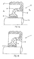
- Fig. 1b An example of this is shown in which the seal 1 further comprises a plurality of stiffening ribs 10, which extend radially from a first connection point on the sleeve-like section 3 to a second connection point on the resilient section 7.
- the material of the sleeve-like section has a higher coefficient of thermal expansion than the shaft material.
- the sleeve-like section 3 may be made of a rubber material such as NBR, or a plastic material such as PTFE, or a metal such as bronze.
- the coefficient of thermal expansion of rubbers lies in the range of 16 to 22 ⁇ 10 -6 K -1 . If the sleeve-like section 3 is mounted with a slight interference fit, the greater thermal expansion of a rubber sleeve-like section relative to the thermal expansion of a steel shaft will ensure low-friction conditions during operation.
- a seal according to the invention may also be provided with means to enhance contamination exclusion.
- the resilient section 7 of the seal 1 may comprise a non-contacting dust lip 26 at the airside 9 of the sleeve-like section 3.
- a dust cover 28 may be bonded to the resilient section 7 at the airside 9 of the seal 1.
Landscapes
- Engineering & Computer Science (AREA)
- General Engineering & Computer Science (AREA)
- Mechanical Engineering (AREA)
- Sealing Devices (AREA)
- Sealing With Elastic Sealing Lips (AREA)
Description
- The present invention concerns a seal for sealing a gap between relatively rotatable components.
- Seal assemblies are widely applied to seal a gap between relatively rotatable components; for example, the gap between a revolving shaft or axle and the housing bore of a motor. The seals serve to retain lubricant within the motor and to exclude the entry of contaminants. Both of these aspects are important for proper running of the motor and the prevention of early failure. A typical seal comprises an outer casing to which a sealing element is bonded. Elastomeric materials, such as nitrile rubber, may be used for the sealing element. The outer casing seals statically against the housing bore. The sealing element seals against a counterface of the e.g. shaft and provides dynamic sealing during rotational conditions and static sealing during stationary conditions.
- Seals that are designed to retain oil or a low-viscosity fluid are generally spring loaded, to ensure static and dynamic tightness. In other words, the sealing element has a certain preload to keep it pressed against the rotating component and this leads to additional friction and heat generation at the seal interface.
- Another factor which must be taken into account with regard to seals is misalignment. This can be shaft-to-bore misalignment, which is the amount by which the shaft is off centre with respect to the centre of the housing bore; dynamic runout, which is a measure of the amount by which the shaft does not rotate around its true centre; or a combination of both. Due to manufacturing and assembly inaccuracies, some misalignment and runout is always present and seals are generally designed to accommodate these eccentricities up to predefined maximum values. In applications where significant misalignments must be accommodated, a high spring preload in a lip seal is advantageous. In a crankshaft sealing application, for example, random shaft defections caused by piston slap may occur, and a high preload helps ensure that the sealing element remains in contact with the shaft, despite the rotational eccentricities. The higher preload, however, increases the friction, which leads to a higher energy consumption and greater energy losses.
- The
US patent application 2006/0038354 Al - The UK patent application
GB 2 417 993 A - The
US Patent 5,137,285 relates to a sealing system consisting of a commercially-available shaft seal having a covering sing pre-arranged separately outside the conventional shaft seal. - Thus, it is an object of the invention to provide an improved seal which may be mounted to seal a gap between two relatively rotatable components.
- This is achieved according to the invention by subject of
claim 1. Advantageous embodiments are described in the dependent claims. - A sleeve-like section of the seal is made of a stiff material so that in the unmounted condition, it retains its sleeve-like shape and remains substantially parallel to an axial centerline of the seal. A stiff sleeve is advantageous, as it enables optimal positioning of the sleeve relative to the component to be sealed, while the precise relative dimensioning allows optimal sealing performance. During rotational conditions, any rotational eccentricities are accommodated by the resilient section, which acts like a hinge. It does not exert a preloaded force on the sleeve-like section, and friction is therefore minimized. The resilient section must be able to withstand the friction torque generated at the sealing interface, as well as potential pressure differentials between an axially inner and axially outer side of the seal. If the sleeve-like section is mounted with a slight interference fit, the torque at start-up may be relatively high.
- Thus according to a further aspect of the invention, the seal may be provided with stiffening means, such as a plurality of ribs or grooves extending radially from a first connection point on the sleeve-like section to a second connection point on the resilient section.
- The sleeve-like section may be made from a variety of materials including, but not restricted to, plastics such as Polytetrafluoroethylene (PTFE) and Polyurethane; metals such as bronze or sinter metal; or rubbers such as Nitrile Acrylonitrile Butadiene (NBR) or a combination of these materials. When made of rubber, the sleeve-like section and the resilient section may be made from the same material, where the two sections are integrally formed as a single piece.
- When executed in rubber or plastic, the inner diameter of the sleeve-like section relative to the outer diameter of the rotatable component may be selected to have a value smaller than one in the specified range. The advantage of a slight interference fit is that the sleeve-like section provides static sealing. When executed in metal, the inner diameter of the sleeve-like section relative the outer diameter of the rotatable component is preferably selected to have a value bigger than one in the specified range, so that it may be mounted with a slight clearance fit. A metal sleeve-like section has the advantage of greater wear resistance, thermal resistance and chemical resistance.
- According to a further aspect of the invention, the material of the sleeve-like section is selected with reference to its coefficient of thermal expansion, αSLEEVE, and with reference to the coefficient of thermal expansion of the material of the rotatable component. During operation, the seal temperature will rise due to frictional torque or due to heat transfer from the rotatable component to the sleeve-like section, meaning that the sleeve-like section will experience thermal expansion. Typically, the rotatable component will be a steel shaft, with a coefficient of thermal expansion, αSHAFT, of approximately 10 · 10-6 K-1. The material of the sleeve-like section is then suitably selected with reference to a given difference in diameter, DSLEEVE - DSHAFT, such that at a minimum expected rise in temperature, the inner diameter of the sleeve-like section increases due to thermal expansion by an amount that is at least equal to an increase in the outer diameter of the rotatable component due to thermal expansion plus a predefined amount, X, where X = 2g - (DSEAL - DSHAFT), and where g is a predefined desirable gap between the inner diameter DSEAL and outer diameter DSHAFT during operation.
- In practice, this means that the material of the sleeve-like section has a higher coefficient of thermal expansion than the shaft material. The coefficient of thermal expansion of rubbers, for example, lies in the range of 16 to 22·10-6 K-1. If the sleeve-like section is mounted with a slight interference fit, the greater thermal expansion of the sleeve-like section relative to the thermal expansion of the rotatable component will ensure low-friction conditions during operation. According to a further aspect of the invention, sealing performance may be enhanced by providing the sealing surface of the sleeve-like portion with hydrodynamic means. These may take the form of one or more sets of helical protrusions (for example ribs) or helical recesses (for example a spiral thread). The helical protrusions or recesses may be unidirectional, meaning that the helices are oriented with respect to the rotational direction of the rotatable component such that during rotation, a pumping action is realized which pumps the fluid to be retained towards the fluid-side of the seal. If the rotatable component is bidirectional, the sealing surface of the sleeve-like section may be provided with bidirectional helical recesses or helical protrusions, to enable pumping of the fluid in the desired direction, regardless of the rotational direction of the e.g. shaft.
- The helical protrusions or recesses may form a continuous helix along the entire length the sealing surface. If the sleeve-like section is mounted with a slight interference fit, the helix could provide a path via which fluid might escape during static conditions. In the case of an interference fit, the helical protrusions or recesses are preferably provided on only a portion of the sealing surface or, the helix should be interrupted, so that the sleeve-like section has a solid annular surface in contact with the counterface of the rotatable component. The solid annular surface then acts as barrier for any fluid during static conditions. In the case of a clearance fit of the sleeve-like section, the seal is preferably provided with at least one flexible lip. The at least one flexible lip is then adapted to seal against the counterface of the rotatable component at the fluid side of the sleeve-like section and/or at the 'air' side of the sleeve-like section. The flexible lip may be suitably angled such that the lip opens due to the pumping action of the hydrodynamic means on the sleeve-like section, but closes when there is no rotation, thereby serving as a static seal.
- In addition to the sealing surface, one or both end faces of the sleeve-like section may be provided with hydrodynamic means. For example, an end face could be provided with a sinusoidal surface geometry or with ramps in the form of a saw-tooth pattern, to direct the fluid to the fluid side of the seal. At the fluid side, the end face could also be executed with a lead-in chamfer, to facilitate mounting of the inventive seal.
- Hydrodynamic means to improve sealing performance may also be provided on the seal counterface, i.e. on the outer diameter of the rotatable component. As will be clear to persons skilled in the art, the seal counterface may also be formed by a radially outer surface of a wear sleeve. Wear sleeves are often used if the surface of the rotatable component does not possess the required quality or is damaged. One or more sets of helical recesses or helical protrusions can be provided on the seal counterface and, as described for the sealing surface of the sleeve-like section, the helices may be unidirectional or bidirectional and continuous or non-continuous. In one embodiment of a seal according to the invention, the wear sleeve is an integral component of the seal, which is then mounted as a unit around the rotatable component. The wear sleeve is mounted with a press fit, so that it rotates with the e.g. shaft.
- When the inventive seal is executed as a unit, the wear sleeve will generally comprise a flinger component, which acts as a barrier to contaminants and, during rotational conditions, dynamically repels contaminants. A seal according to the invention may also be provided with other means to exclude contaminants. For example, the resilient section may further comprise a non-contacting dust lip at an axially outer side of the sleeve-like section. The seal could also be provided with a dust cover.
- A seal according to the invention comprises a stiff, sleeve-like sealing element which, in mounted condition, has extremely little play relative to the rotatable component. This minimizes friction during rotational conditions. The inventive seal also provides excellent dynamic and static sealing performance. Other advantages of the invention will become apparent from the detailed description and accompanying figures.
- The invention will now be described in more detail for explanatory, and in no sense limiting, purposes, with reference to the following figures, in which:
- Fig. 1a - 1b
- illustrate a partial radial view of embodiments of a seal according to the invention.
- Fig. 2a - 2b
- illustrate examples of hydrodynamic means on sealing surface of sleeve-like section.
- Fig. 3
- illustrates a seat according to the invention executed as a unit.
- Fig. 4
- illustrates an example of hydrodynamic means on an end face of the sleeve-like section.
- Fig. 5a - 5d
- illustrate further embodiments of a seal according to the invention.
- An example of a seal according to the invention is shown in
Fig. 1a . Theseal 1 comprises a sleeve-like section 3, which is adapted to be mounted around a rotatable component such as a shaft 4. The sleeve-like section 3 is connected to anouter casing 5 of the seat by means of aresilient section 7. Theouter casing 5 is adapted to be mounted in e.g. a bore of a housing, and may (as shown) consist of a metal flange with a rubber outside diameter. Other variations are possible, such as a full rubber or a full metal casing. Theouter casing 5 seals statically against the housing bore (not shown) and the sleeve-like section 3 provides dynamic sealing during rotation of the shaft 4. Such a seal may be used seal a gap between a rotatable and a non-rotatable component and thereby retain fluid at afluid side 6 of the seal in relation to anairside 9 of the seal. - Law-friction, dynamic sealing is obtained in that the sleeve-
like section 3 is precisely dimensioned in relation to the shaft 4 it is adapted to be mounted around. Specifically, the sleeve-like section 3 has an inner diameter, DSLEEVE, which is selected with reference to an outer diameter of the shaft, DSHAFT, such that in anunmounted condition 0,9 ≤ DSEAL / DSHAFT ≤ 1,1. Thus, a value smaller than one in the specified range leads to a slight interference fit when the sleeve-like section 3 is mounted around the shaft 4, and a value bigger than one leads to a slight clearance fit. - The sleeve-
like section 3 may be made of a stiff material so that in the unmounted condition, it retains its sleeve-like shape and remains substantially parallel to an axial centerline of the seal. A stiff sleeve enables optimal positioning of the sleeve relative to the shaft to be sealed, while the precise relative dimensioning allows optimal sealing performance. In order to accommodate any rotational eccentricities between the shaft 4 and the housing bore, theresilient section 7 of the seal further comprises anarcuate portion 8. Thisarcuate portion 8 acts like a hinge, and does not exert a preloaded force on the sleeve-like section 3. As a result, the friction torque generated is substantially lower compared with conventional seal designs. - The
resilient section 7 must be able to withstand the friction torque that is generated at the sealing interface, as well as potential pressure differentials between thefluid side 6 and theairside 9 of theseal 1. Moreover, if the sleeve-like section 3 is mounted with a slight interference fit, the torque at start-up may be relatively high. Therefore, in an advantageous further development of the invention, the seal may be provided with stiffening means. An example of this is shown inFig. 1b , in which theseal 1 further comprises a plurality of stiffeningribs 10, which extend radially from a first connection point on the sleeve-like section 3 to a second connection point on theresilient section 7. - According to a further aspect of the invention, the material of the sleeve-
like section 3 is selected with reference to its coefficient of thermal expansion, αSLEEVE, in relation to the coefficient of thermal expansion of the shaft material. During operation, the seal temperature will rise due to frictional torque or due to heat transfer from the shaft 4 to the sleeve-like section 3, meaning that the sleeve-like section will experience thermal expansion. Typically, the shaft will be a steel shaft, with a coefficient of thermal expansion, αSHAFT, of approximately 10 · 10-6 K-1. The material of the sleeve-like section 3 is then suitably selected with reference to a given difference in diameter, DSLEEVE - DSHAFT, such that at a minimum expected rise in temperature, the inner diameter of the sleeve-like section increases due to thermal expansion by an amount that is at least equal to an increase in the outer diameter of the shaft to thermal expansion plus a predefined amount, X, where X = 2g - (DSEAL - DSHAFT), and where g is a predefined desirable gap between the inner diameter DSLEEVE and outer diameter DSHAFT during operation. - In practice, this means that the material of the sleeve-like section has a higher coefficient of thermal expansion than the shaft material. The sleeve-
like section 3 may be made of a rubber material such as NBR, or a plastic material such as PTFE, or a metal such as bronze. The coefficient of thermal expansion of rubbers, for example, lies in the range of 16 to 22·10-6 K-1. If the sleeve-like section 3 is mounted with a slight interference fit, the greater thermal expansion of a rubber sleeve-like section relative to the thermal expansion of a steel shaft will ensure low-friction conditions during operation. - During operation, sealing performance may be further enhanced by providing the sealing surface of the sleeve-like section with hydrodynamic means. Examples of suitable hydrodynamic means are shown in
Fig. 2a and Fig. 2b . These may take the form of one or more sets of helical protrusions (a spiral thread), as shown inFig. 2a , or helical recesses (ribs), as shown inFig. 2B . Thehelical protrusions 12 orhelical recesses 14 may be unidirectional, meaning that the helices are oriented with respect to the rotational direction of the shaft such that during rotation, a pumping action is realized which pumps the fluid to be retained towards the fluid-side of the seal. If the shaft is bidirectional, the sealingsurface 16 of the sleeve-like section may be provided with bidirectional helical recesses or helical protrusions, to enable pumping of the fluid in the desired direction, regardless of the rotational direction of the shaft. - The
helical protrusions 12 or recesses 14 may form a continuous helix along the entire length the sealingsurface 16. If the sleeve-like section 3 is mounted with a slight interference fit, the helix could provide a path via which fluid might escape during static conditions. In the case of an interference fit, thehelical protrusions 12 or recesses 14 are preferably provided on only a portion of the sealingsurface 16 or, the helix should be interrupted, so that the sleeve-like section 3 has a solid annular surface in contact with the shaft. The solid annular surface then acts as barrier for any fluid during static conditions. - Hydrodynamic means to improve sealing performance may also be provided on the seal counterface, i.e. on the outer diameter of the rotating component. Thus, one or more sets of
helical protrusions 12 orhelical recesses 14 can be provided on the seal counterface and, as described for the sealingsurface 16 of the sleeve-like section 3, the helices may be unidirectional or bidirectional and continuous or non-continuous. As will be clear to persons skilled in the art, the seal counterface may also be formed by a wear sleeve component press-fitted onto the shaft. In one embodiment of a seal according to the invention, as shown inFig. 3 , thewear sleeve 18 is an integral component of theseal 1, which is then mounted as a unit around the shaft 4. - In a further advantageous development of the invention, one or both end faces of the sleeve-like section may be provided with hydrodynamic means.
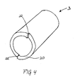
Fig. 4 shows a perspective view of a sleeve-like section 3 provided with one example of hydrodynamic means on an end face. Here, theend face 20 has been provided withramps 22 in its surface. The ramps may have various geometries, e.g. a straight or rounded saw-tooth pattern. One or both of the end-faces 20 could also be provided with a sinusoidal surface geometry, or some other varying surface geometry. The hydrodynamic means may be adapted such that during rotational conditions, fluid is directed towards the fluid side of the seal. Alternatively, at the airside of the sleeve-like section 3, hydrodynamic means on the end face could be adapted to direct contaminants away from the seal. - According to the invention, the sleeve-like section may be mounted with a slight interference fit or a slight clearance fit. In order to provide static sealing in the case of a clearance fit of the sleeve-like section, the seal is preferably provided with at least a first flexible sealing lip. Such an embodiment of the invention is shown in
Fig. 5a , where theresilient section 7 of theseal 1 comprises aflexible sealing lip 22, which seals against the shaft 4 at thefluid side 6 of the sleeve-like section 3. The seal may also be provided with a second flexible sealing lip, as shown inFig. 5b . Here, theresilient section 7 of theseal 1 comprises aflexible sealing lip 22, which seals against the shaft 4 at theairside 9 of the sleeve-like section 3. The first and/or second flexible sealinglip 22 may be suitably angled such that the lip opens due to the pumping action of the hydrodynamic means on the sleeve-like section 3, but closes when there is no rotation, thereby serving as a static seal. - A seal according to the invention may also be provided with means to enhance contamination exclusion. As shown in
Fig. 5c , theresilient section 7 of theseal 1 may comprise anon-contacting dust lip 26 at theairside 9 of the sleeve-like section 3. In a further embodiment, as shown inFig. 5d , a dust cover 28 may be bonded to theresilient section 7 at theairside 9 of theseal 1. - A number of aspects/embodiments of the invention have been described. It is to be understood that each aspect/embodiment may be combined with any other aspect/embodiment. Moreover the invention is not restricted to the described embodiments, but may be varied within the scope of the accompanying patent claims.
-
- 1
- Seal
- 3
- Sleeve-like section
- 4
- Shaft
- 5
- Outer casing
- 6
- Fluid side of seal
- 7
- Resilient section
- 8
- Arcuate portion
- 9
- Air side of seal
- 10
- Stiffening ribs
- 12
- Helical protrusions
- 14
- Helical recesses
- 16
- Sealing surface of sleeve-like section
- 18
- Wear sleeve
- 20
- End face of sleeve-like section
- 22
- Flexible sealing lip
- 26
- Dust lip
- 28
- Dust cover
Claims (13)
- A seal to seal a gap between a rotatable component (4, 18) and a non-rotatable component comprises:- A fastening section adaptable to be fixedly mounted in relation to the non-rotatable component,- a sleeve-like section (3) adaptable to be mounted around the rotatable component (4, 18), wherein the sleeve-like section (3) is made of a stiff material,- a resilient section (7) between the sleeve-like and fastening section comprising an arcuate portion (8) ; characterized in that in an unmounted condition, the sleeve-like section (3) has an inner diameter, DSEAL, with a predefined magnitude relative to an outer diameter of the rotating component, DSHAFT, such that 0,9 ≤ DSEAL/ DSHAFT ≤ 1,1, and that the resilient section is not exenting a preload force on the sleeve like section.
- A seal according to claim 1, characterized in that in the unmounted condition, the sleeve-like section (3) is essentially parallel to an axial centerline of the seal.
- A seal according to claim 1 or 2, characterized in that the fastening section (7) comprises stiffening means (10).
- A seal according to any of the preceding claims, characterized in that the sleeve-like section (3) of the seal (1) is made of a material with a certain coefficient of thermal expansion, which material is selected in relation to a coefficient of thermal expansion of the rotatable component (4) such that at a minimum expected rise in temperature during relative rotation between the sleeve-like section (3) and the rotatable component (4, 18), an increase in the inner diameter of the sleeve-like section due to thermal expansion is at least equal to an increase in the outer diameter of the rotatable component due to thermal expansion plus a predefined amount, X, where X = 2g - (DSEAL - DSHAFT), and where g is a predefined desirable gap between the inner diameter DSEAL and outer diameter DSHAFT during relative rotation.
- A seal according to any of preceding claims, characterized in that the sleeve-like section (3) and the resilient section (7) are integrally formed as a single piece.
- A seal according to any of the preceding claims, characterized in that a sealing surface (16) of the sleeve-like section (3) is provided with hydrodynamic means, particularly the hydrodynamic means is formed by at least one set of helical protrusions (12) or helical recesses (14) in the sealing surface (16) of the sleeve-like section (3), particularly the helical protrusions (12) or helical recesses (14) are unidirectional or bidirectional, and/or form a continuous helix or non-continuous helix.
- A seal according to any of the preceding claims, characterized in that at least one end face (20) of the sleeve-like section (3) is provided with hydrodynamic means, particularly the hydrodynamic means is in the form of a variations in the surface geometry of the end face (20).
- A seal according to any of the preceding claims, characterized in that at a mounting side of the seal, the sleeve-like section (3) has a lead-in chamfer edge.
- A seal according to any of the preceding claims, characterized in that the seal further comprises at least one flexible sealing lip (22) adaptable to seal against the rotatable component (4, 18) at an axially outer side and/or an axially inner side in relation to the sleeve-like section (3).
- A seal according to any of the preceding claims, characterized in that the seal further comprises a wear sleeve component (18) adaptable to be mounted on the rotatable component.
- A seal according to any of the preceding claims, characterized in that the seal comprises a non-contacting dust lip (26).
- A seal according to any of the preceding claims, characterized in that the seal (1) comprises a dust cover (28).
- A seal according to any of the preceding claims, characterized in that the relation of the inner diameter DSEAL to the outer diameter DSHAFT is such that 0,95 ≤ DSEAL / DSHAFT ≤ 1,05.
Applications Claiming Priority (1)
| Application Number | Priority Date | Filing Date | Title |
|---|---|---|---|
| PCT/EP2007/010307 WO2009068050A1 (en) | 2007-11-28 | 2007-11-28 | Seal |
Publications (2)
| Publication Number | Publication Date |
|---|---|
| EP2229546A1 EP2229546A1 (en) | 2010-09-22 |
| EP2229546B1 true EP2229546B1 (en) | 2013-03-13 |
Family
ID=39712110
Family Applications (1)
| Application Number | Title | Priority Date | Filing Date |
|---|---|---|---|
| EP07856272A Not-in-force EP2229546B1 (en) | 2007-11-28 | 2007-11-28 | Seal |
Country Status (4)
| Country | Link |
|---|---|
| US (1) | US8651496B2 (en) |
| EP (1) | EP2229546B1 (en) |
| CN (1) | CN101878388B (en) |
| WO (1) | WO2009068050A1 (en) |
Families Citing this family (8)
| Publication number | Priority date | Publication date | Assignee | Title |
|---|---|---|---|---|
| WO2011161492A1 (en) * | 2010-06-23 | 2011-12-29 | Aktiebolaget Skf | Friction device for a bearing assembly, bearing and bearing assembly comprising such a friction device |
| US20120306156A1 (en) * | 2011-06-01 | 2012-12-06 | Alma Products Company | Compressor seal |
| US20130078090A1 (en) * | 2011-09-22 | 2013-03-28 | Craig A. Beers | Air cycle machine shaft support assembly |
| DE102012018652B4 (en) * | 2012-09-20 | 2016-03-10 | Eagleburgmann Germany Gmbh & Co. Kg | Cartridge assembly with sealing ring and agitator with such a cartridge assembly |
| US20150014937A1 (en) * | 2013-03-07 | 2015-01-15 | Rolls-Royce Corporation | Seal assembly and shaft therefor |
| DE102013207029B4 (en) | 2013-04-18 | 2016-05-04 | Aktiebolaget Skf | Radial shaft seal arrangement |
| CN109307077B (en) * | 2017-07-27 | 2022-11-29 | 舍弗勒技术股份两合公司 | Seal assembly |
| DE102021206769A1 (en) * | 2021-06-29 | 2022-12-29 | Trelleborg Sealing Solutions Germany Gmbh | Rotary seal arrangement with rotary seal and with foam ring arranged on the oil side |
Citations (2)
| Publication number | Priority date | Publication date | Assignee | Title |
|---|---|---|---|---|
| EP0213652A1 (en) * | 1985-07-15 | 1987-03-11 | Ihc Holland N.V. | Shaft seal |
| US20050156384A1 (en) * | 2004-01-15 | 2005-07-21 | Toth David M. | Elastomeric hinged seal |
Family Cites Families (21)
| Publication number | Priority date | Publication date | Assignee | Title |
|---|---|---|---|---|
| USRE24940E (en) * | 1958-05-09 | 1961-02-28 | Hub sealing means | |
| US3554561A (en) * | 1966-09-06 | 1971-01-12 | Gen Motors Corp | Unidirectional pumping seal |
| US3920250A (en) * | 1974-02-19 | 1975-11-18 | Phillip R Eklund | High pressure shaft seal structure |
| US4194745A (en) * | 1979-05-02 | 1980-03-25 | Mcdougal Thomas L | Controlled clearance seal |
| DE2949839C2 (en) * | 1979-12-12 | 1983-05-26 | Fa. Carl Freudenberg, 6940 Weinheim | Sealing ring |
| US4300777A (en) * | 1980-06-16 | 1981-11-17 | General Motors Corporation | Fluid seal |
| IL65289A0 (en) * | 1982-03-19 | 1982-05-31 | Lipschitz Abraham | Hydrodynamic non-contacting seal for rotary machines |
| US4491332A (en) * | 1983-11-07 | 1985-01-01 | Eaton Corporation | Shaft seal and means to effect radial movement of sealing lip |
| US4553760A (en) * | 1984-11-19 | 1985-11-19 | Caterpillar Tractor Co. | Flexible seal for a spherical joint |
| DE3765249D1 (en) * | 1986-03-24 | 1990-10-31 | Zahnradfabrik Friedrichshafen | SEALING RING FOR ARRANGEMENT BETWEEN AXIAL AND ROTATING MACHINE PARTS. |
| US5456475A (en) * | 1988-04-28 | 1995-10-10 | Skf Usa Inc. | Protected seal assembly and protective filter unit therefor |
| US4844484A (en) * | 1988-06-28 | 1989-07-04 | Dana Corporation | Floating lip seal with reinforced flexible portion |
| US5082294A (en) * | 1990-09-20 | 1992-01-21 | Federal-Mogul Corporation | Heat conducting wear sleeve assembly for lubricant seals |
| US6334619B1 (en) * | 1998-05-20 | 2002-01-01 | Kalsi Engineering, Inc. | Hydrodynamic packing assembly |
| DE10353304A1 (en) * | 2003-11-10 | 2005-06-09 | Kaco Gmbh + Co. Kg | Sealing ring, in particular radial shaft sealing ring |
| US7419165B2 (en) * | 2004-08-18 | 2008-09-02 | Federal-Mogul World Wide, Inc. | Seal assembly and method of manufacturing the same |
| GB2417993A (en) | 2004-09-10 | 2006-03-15 | Boc Group Plc | A shaft seal for sealing between a rotary shaft and a housing |
| KR100871644B1 (en) * | 2004-11-02 | 2008-12-02 | 가부시키가이샤 고마쓰 세이사쿠쇼 | Bearing seal |
| US7854433B2 (en) * | 2005-02-24 | 2010-12-21 | Freudenberg-Nok General Partnership | Dynamic seal |
| US7806411B2 (en) * | 2006-11-27 | 2010-10-05 | A.W. Chesterton Company | Radial seal assembly |
| WO2010088344A2 (en) * | 2009-01-28 | 2010-08-05 | Federal-Mogul Corporation | Radial shaft seal, radial shaft seal assembly and method of installation |
-
2007
- 2007-11-28 EP EP07856272A patent/EP2229546B1/en not_active Not-in-force
- 2007-11-28 WO PCT/EP2007/010307 patent/WO2009068050A1/en active Application Filing
- 2007-11-28 US US12/745,154 patent/US8651496B2/en not_active Expired - Fee Related
- 2007-11-28 CN CN200780101741.7A patent/CN101878388B/en not_active Expired - Fee Related
Patent Citations (2)
| Publication number | Priority date | Publication date | Assignee | Title |
|---|---|---|---|---|
| EP0213652A1 (en) * | 1985-07-15 | 1987-03-11 | Ihc Holland N.V. | Shaft seal |
| US20050156384A1 (en) * | 2004-01-15 | 2005-07-21 | Toth David M. | Elastomeric hinged seal |
Also Published As
| Publication number | Publication date |
|---|---|
| US20110031701A1 (en) | 2011-02-10 |
| CN101878388A (en) | 2010-11-03 |
| EP2229546A1 (en) | 2010-09-22 |
| CN101878388B (en) | 2014-03-12 |
| WO2009068050A1 (en) | 2009-06-04 |
| US8651496B2 (en) | 2014-02-18 |
Similar Documents
| Publication | Publication Date | Title |
|---|---|---|
| EP2229546B1 (en) | Seal | |
| US6428013B1 (en) | Reverse seal | |
| EP0835398B1 (en) | Skew and twist resistant hydrodynamic rotary shaft seal | |
| US6120036A (en) | Extrusion resistant hydrodynamically lubricated rotary shaft seal | |
| US6685194B2 (en) | Hydrodynamic rotary seal with varying slope | |
| US6264205B1 (en) | Rotary cartridge seals with retainer | |
| US5186472A (en) | Unitized radial shaft seal | |
| EP2492551B1 (en) | Hydrodynamic rotary seal with opposed tapering seal lips | |
| US7066471B2 (en) | Lip-type shaft seal | |
| EP2916048B1 (en) | Seal assembly | |
| US20060022414A1 (en) | Rotary cartridge seals with composite retainer | |
| JP2004293789A (en) | Seal ring | |
| US20040104536A1 (en) | Hydrodynamic rotary seal | |
| KR20070047830A (en) | Seal assembly and method of manufacturing the same | |
| US4436317A (en) | Cassette seal having a counterring free from unrelieved internal stress | |
| CN110382932B (en) | Sealing device | |
| JP5071886B2 (en) | Seal structure | |
| US4595206A (en) | Seal with inner and outer slidably contacting rings | |
| KR20140137408A (en) | Radial shaft seal with static and hydrodynamic sealing features | |
| US10844960B2 (en) | Crankshaft seal design | |
| US8720903B2 (en) | Fluid seal assembly | |
| EP3887696B1 (en) | Seal assembly with anti-rotation and stability features | |
| JP4120816B2 (en) | Sealing device | |
| KR20230145489A (en) | Sealing structure and sealing method | |
| JP2021167641A (en) | Sealing device |
Legal Events
| Date | Code | Title | Description |
|---|---|---|---|
| PUAI | Public reference made under article 153(3) epc to a published international application that has entered the european phase |
Free format text: ORIGINAL CODE: 0009012 |
|
| 17P | Request for examination filed |
Effective date: 20100628 |
|
| AK | Designated contracting states |
Kind code of ref document: A1 Designated state(s): AT BE BG CH CY CZ DE DK EE ES FI FR GB GR HU IE IS IT LI LT LU LV MC MT NL PL PT RO SE SI SK TR |
|
| AX | Request for extension of the european patent |
Extension state: AL BA HR MK RS |
|
| DAX | Request for extension of the european patent (deleted) | ||
| 17Q | First examination report despatched |
Effective date: 20110304 |
|
| GRAP | Despatch of communication of intention to grant a patent |
Free format text: ORIGINAL CODE: EPIDOSNIGR1 |
|
| GRAS | Grant fee paid |
Free format text: ORIGINAL CODE: EPIDOSNIGR3 |
|
| GRAA | (expected) grant |
Free format text: ORIGINAL CODE: 0009210 |
|
| AK | Designated contracting states |
Kind code of ref document: B1 Designated state(s): AT BE BG CH CY CZ DE DK EE ES FI FR GB GR HU IE IS IT LI LT LU LV MC MT NL PL PT RO SE SI SK TR |
|
| REG | Reference to a national code |
Ref country code: GB Ref legal event code: FG4D |
|
| REG | Reference to a national code |
Ref country code: AT Ref legal event code: REF Ref document number: 601002 Country of ref document: AT Kind code of ref document: T Effective date: 20130315 Ref country code: CH Ref legal event code: EP |
|
| REG | Reference to a national code |
Ref country code: IE Ref legal event code: FG4D |
|
| REG | Reference to a national code |
Ref country code: DE Ref legal event code: R096 Ref document number: 602007029124 Country of ref document: DE Effective date: 20130508 |
|
| PG25 | Lapsed in a contracting state [announced via postgrant information from national office to epo] |
Ref country code: LT Free format text: LAPSE BECAUSE OF FAILURE TO SUBMIT A TRANSLATION OF THE DESCRIPTION OR TO PAY THE FEE WITHIN THE PRESCRIBED TIME-LIMIT Effective date: 20130313 Ref country code: BG Free format text: LAPSE BECAUSE OF FAILURE TO SUBMIT A TRANSLATION OF THE DESCRIPTION OR TO PAY THE FEE WITHIN THE PRESCRIBED TIME-LIMIT Effective date: 20130613 Ref country code: SE Free format text: LAPSE BECAUSE OF FAILURE TO SUBMIT A TRANSLATION OF THE DESCRIPTION OR TO PAY THE FEE WITHIN THE PRESCRIBED TIME-LIMIT Effective date: 20130313 Ref country code: ES Free format text: LAPSE BECAUSE OF FAILURE TO SUBMIT A TRANSLATION OF THE DESCRIPTION OR TO PAY THE FEE WITHIN THE PRESCRIBED TIME-LIMIT Effective date: 20130624 |
|
| REG | Reference to a national code |
Ref country code: AT Ref legal event code: MK05 Ref document number: 601002 Country of ref document: AT Kind code of ref document: T Effective date: 20130313 |
|
| REG | Reference to a national code |
Ref country code: NL Ref legal event code: VDEP Effective date: 20130313 |
|
| REG | Reference to a national code |
Ref country code: LT Ref legal event code: MG4D |
|
| PG25 | Lapsed in a contracting state [announced via postgrant information from national office to epo] |
Ref country code: GR Free format text: LAPSE BECAUSE OF FAILURE TO SUBMIT A TRANSLATION OF THE DESCRIPTION OR TO PAY THE FEE WITHIN THE PRESCRIBED TIME-LIMIT Effective date: 20130614 Ref country code: LV Free format text: LAPSE BECAUSE OF FAILURE TO SUBMIT A TRANSLATION OF THE DESCRIPTION OR TO PAY THE FEE WITHIN THE PRESCRIBED TIME-LIMIT Effective date: 20130313 Ref country code: SI Free format text: LAPSE BECAUSE OF FAILURE TO SUBMIT A TRANSLATION OF THE DESCRIPTION OR TO PAY THE FEE WITHIN THE PRESCRIBED TIME-LIMIT Effective date: 20130313 Ref country code: FI Free format text: LAPSE BECAUSE OF FAILURE TO SUBMIT A TRANSLATION OF THE DESCRIPTION OR TO PAY THE FEE WITHIN THE PRESCRIBED TIME-LIMIT Effective date: 20130313 |
|
| PG25 | Lapsed in a contracting state [announced via postgrant information from national office to epo] |
Ref country code: BE Free format text: LAPSE BECAUSE OF FAILURE TO SUBMIT A TRANSLATION OF THE DESCRIPTION OR TO PAY THE FEE WITHIN THE PRESCRIBED TIME-LIMIT Effective date: 20130313 |
|
| PG25 | Lapsed in a contracting state [announced via postgrant information from national office to epo] |
Ref country code: PT Free format text: LAPSE BECAUSE OF FAILURE TO SUBMIT A TRANSLATION OF THE DESCRIPTION OR TO PAY THE FEE WITHIN THE PRESCRIBED TIME-LIMIT Effective date: 20130715 Ref country code: IS Free format text: LAPSE BECAUSE OF FAILURE TO SUBMIT A TRANSLATION OF THE DESCRIPTION OR TO PAY THE FEE WITHIN THE PRESCRIBED TIME-LIMIT Effective date: 20130713 Ref country code: SK Free format text: LAPSE BECAUSE OF FAILURE TO SUBMIT A TRANSLATION OF THE DESCRIPTION OR TO PAY THE FEE WITHIN THE PRESCRIBED TIME-LIMIT Effective date: 20130313 Ref country code: CZ Free format text: LAPSE BECAUSE OF FAILURE TO SUBMIT A TRANSLATION OF THE DESCRIPTION OR TO PAY THE FEE WITHIN THE PRESCRIBED TIME-LIMIT Effective date: 20130313 Ref country code: RO Free format text: LAPSE BECAUSE OF FAILURE TO SUBMIT A TRANSLATION OF THE DESCRIPTION OR TO PAY THE FEE WITHIN THE PRESCRIBED TIME-LIMIT Effective date: 20130313 Ref country code: AT Free format text: LAPSE BECAUSE OF FAILURE TO SUBMIT A TRANSLATION OF THE DESCRIPTION OR TO PAY THE FEE WITHIN THE PRESCRIBED TIME-LIMIT Effective date: 20130313 Ref country code: EE Free format text: LAPSE BECAUSE OF FAILURE TO SUBMIT A TRANSLATION OF THE DESCRIPTION OR TO PAY THE FEE WITHIN THE PRESCRIBED TIME-LIMIT Effective date: 20130313 Ref country code: NL Free format text: LAPSE BECAUSE OF FAILURE TO SUBMIT A TRANSLATION OF THE DESCRIPTION OR TO PAY THE FEE WITHIN THE PRESCRIBED TIME-LIMIT Effective date: 20130313 |
|
| PG25 | Lapsed in a contracting state [announced via postgrant information from national office to epo] |
Ref country code: PL Free format text: LAPSE BECAUSE OF FAILURE TO SUBMIT A TRANSLATION OF THE DESCRIPTION OR TO PAY THE FEE WITHIN THE PRESCRIBED TIME-LIMIT Effective date: 20130313 Ref country code: CY Free format text: LAPSE BECAUSE OF FAILURE TO SUBMIT A TRANSLATION OF THE DESCRIPTION OR TO PAY THE FEE WITHIN THE PRESCRIBED TIME-LIMIT Effective date: 20130313 |
|
| PLBE | No opposition filed within time limit |
Free format text: ORIGINAL CODE: 0009261 |
|
| STAA | Information on the status of an ep patent application or granted ep patent |
Free format text: STATUS: NO OPPOSITION FILED WITHIN TIME LIMIT |
|
| PG25 | Lapsed in a contracting state [announced via postgrant information from national office to epo] |
Ref country code: DK Free format text: LAPSE BECAUSE OF FAILURE TO SUBMIT A TRANSLATION OF THE DESCRIPTION OR TO PAY THE FEE WITHIN THE PRESCRIBED TIME-LIMIT Effective date: 20130313 |
|
| 26N | No opposition filed |
Effective date: 20131216 |
|
| PG25 | Lapsed in a contracting state [announced via postgrant information from national office to epo] |
Ref country code: IT Free format text: LAPSE BECAUSE OF FAILURE TO SUBMIT A TRANSLATION OF THE DESCRIPTION OR TO PAY THE FEE WITHIN THE PRESCRIBED TIME-LIMIT Effective date: 20130313 |
|
| REG | Reference to a national code |
Ref country code: DE Ref legal event code: R097 Ref document number: 602007029124 Country of ref document: DE Effective date: 20131216 |
|
| REG | Reference to a national code |
Ref country code: CH Ref legal event code: PL |
|
| GBPC | Gb: european patent ceased through non-payment of renewal fee |
Effective date: 20131128 |
|
| PG25 | Lapsed in a contracting state [announced via postgrant information from national office to epo] |
Ref country code: LI Free format text: LAPSE BECAUSE OF NON-PAYMENT OF DUE FEES Effective date: 20131130 Ref country code: CH Free format text: LAPSE BECAUSE OF NON-PAYMENT OF DUE FEES Effective date: 20131130 Ref country code: MC Free format text: LAPSE BECAUSE OF FAILURE TO SUBMIT A TRANSLATION OF THE DESCRIPTION OR TO PAY THE FEE WITHIN THE PRESCRIBED TIME-LIMIT Effective date: 20130313 |
|
| REG | Reference to a national code |
Ref country code: FR Ref legal event code: ST Effective date: 20140731 |
|
| REG | Reference to a national code |
Ref country code: IE Ref legal event code: MM4A |
|
| PG25 | Lapsed in a contracting state [announced via postgrant information from national office to epo] |
Ref country code: IE Free format text: LAPSE BECAUSE OF NON-PAYMENT OF DUE FEES Effective date: 20131128 |
|
| PG25 | Lapsed in a contracting state [announced via postgrant information from national office to epo] |
Ref country code: GB Free format text: LAPSE BECAUSE OF NON-PAYMENT OF DUE FEES Effective date: 20131128 Ref country code: FR Free format text: LAPSE BECAUSE OF NON-PAYMENT OF DUE FEES Effective date: 20131202 |
|
| PG25 | Lapsed in a contracting state [announced via postgrant information from national office to epo] |
Ref country code: TR Free format text: LAPSE BECAUSE OF FAILURE TO SUBMIT A TRANSLATION OF THE DESCRIPTION OR TO PAY THE FEE WITHIN THE PRESCRIBED TIME-LIMIT Effective date: 20130313 |
|
| PG25 | Lapsed in a contracting state [announced via postgrant information from national office to epo] |
Ref country code: LU Free format text: LAPSE BECAUSE OF NON-PAYMENT OF DUE FEES Effective date: 20131128 Ref country code: HU Free format text: LAPSE BECAUSE OF FAILURE TO SUBMIT A TRANSLATION OF THE DESCRIPTION OR TO PAY THE FEE WITHIN THE PRESCRIBED TIME-LIMIT; INVALID AB INITIO Effective date: 20071128 |
|
| PG25 | Lapsed in a contracting state [announced via postgrant information from national office to epo] |
Ref country code: MT Free format text: LAPSE BECAUSE OF FAILURE TO SUBMIT A TRANSLATION OF THE DESCRIPTION OR TO PAY THE FEE WITHIN THE PRESCRIBED TIME-LIMIT Effective date: 20130313 |
|
| PGFP | Annual fee paid to national office [announced via postgrant information from national office to epo] |
Ref country code: DE Payment date: 20160129 Year of fee payment: 9 |
|
| REG | Reference to a national code |
Ref country code: DE Ref legal event code: R119 Ref document number: 602007029124 Country of ref document: DE |
|
| PG25 | Lapsed in a contracting state [announced via postgrant information from national office to epo] |
Ref country code: DE Free format text: LAPSE BECAUSE OF NON-PAYMENT OF DUE FEES Effective date: 20170601 |