DE102012018652B4 - Cartridge assembly with sealing ring and agitator with such a cartridge assembly - Google Patents
Cartridge assembly with sealing ring and agitator with such a cartridge assembly Download PDFInfo
- Publication number
- DE102012018652B4 DE102012018652B4 DE102012018652.5A DE102012018652A DE102012018652B4 DE 102012018652 B4 DE102012018652 B4 DE 102012018652B4 DE 102012018652 A DE102012018652 A DE 102012018652A DE 102012018652 B4 DE102012018652 B4 DE 102012018652B4
- Authority
- DE
- Germany
- Prior art keywords
- sealing ring
- rotating component
- sealing
- cartridge assembly
- lip seal
- Prior art date
- Legal status (The legal status is an assumption and is not a legal conclusion. Google has not performed a legal analysis and makes no representation as to the accuracy of the status listed.)
- Active
Links
Images


Classifications
-
- F—MECHANICAL ENGINEERING; LIGHTING; HEATING; WEAPONS; BLASTING
- F16—ENGINEERING ELEMENTS AND UNITS; GENERAL MEASURES FOR PRODUCING AND MAINTAINING EFFECTIVE FUNCTIONING OF MACHINES OR INSTALLATIONS; THERMAL INSULATION IN GENERAL
- F16J—PISTONS; CYLINDERS; SEALINGS
- F16J15/00—Sealings
- F16J15/16—Sealings between relatively-moving surfaces
- F16J15/32—Sealings between relatively-moving surfaces with elastic sealings, e.g. O-rings
- F16J15/328—Manufacturing methods specially adapted for elastic sealings
-
- F—MECHANICAL ENGINEERING; LIGHTING; HEATING; WEAPONS; BLASTING
- F16—ENGINEERING ELEMENTS AND UNITS; GENERAL MEASURES FOR PRODUCING AND MAINTAINING EFFECTIVE FUNCTIONING OF MACHINES OR INSTALLATIONS; THERMAL INSULATION IN GENERAL
- F16C—SHAFTS; FLEXIBLE SHAFTS; ELEMENTS OR CRANKSHAFT MECHANISMS; ROTARY BODIES OTHER THAN GEARING ELEMENTS; BEARINGS
- F16C33/00—Parts of bearings; Special methods for making bearings or parts thereof
- F16C33/72—Sealings
- F16C33/76—Sealings of ball or roller bearings
-
- F—MECHANICAL ENGINEERING; LIGHTING; HEATING; WEAPONS; BLASTING
- F16—ENGINEERING ELEMENTS AND UNITS; GENERAL MEASURES FOR PRODUCING AND MAINTAINING EFFECTIVE FUNCTIONING OF MACHINES OR INSTALLATIONS; THERMAL INSULATION IN GENERAL
- F16J—PISTONS; CYLINDERS; SEALINGS
- F16J15/00—Sealings
- F16J15/16—Sealings between relatively-moving surfaces
- F16J15/32—Sealings between relatively-moving surfaces with elastic sealings, e.g. O-rings
- F16J15/3204—Sealings between relatively-moving surfaces with elastic sealings, e.g. O-rings with at least one lip
- F16J15/3228—Sealings between relatively-moving surfaces with elastic sealings, e.g. O-rings with at least one lip formed by deforming a flat ring
-
- F—MECHANICAL ENGINEERING; LIGHTING; HEATING; WEAPONS; BLASTING
- F16—ENGINEERING ELEMENTS AND UNITS; GENERAL MEASURES FOR PRODUCING AND MAINTAINING EFFECTIVE FUNCTIONING OF MACHINES OR INSTALLATIONS; THERMAL INSULATION IN GENERAL
- F16J—PISTONS; CYLINDERS; SEALINGS
- F16J15/00—Sealings
- F16J15/16—Sealings between relatively-moving surfaces
- F16J15/32—Sealings between relatively-moving surfaces with elastic sealings, e.g. O-rings
- F16J15/3268—Mounting of sealing rings
-
- F—MECHANICAL ENGINEERING; LIGHTING; HEATING; WEAPONS; BLASTING
- F16—ENGINEERING ELEMENTS AND UNITS; GENERAL MEASURES FOR PRODUCING AND MAINTAINING EFFECTIVE FUNCTIONING OF MACHINES OR INSTALLATIONS; THERMAL INSULATION IN GENERAL
- F16C—SHAFTS; FLEXIBLE SHAFTS; ELEMENTS OR CRANKSHAFT MECHANISMS; ROTARY BODIES OTHER THAN GEARING ELEMENTS; BEARINGS
- F16C17/00—Sliding-contact bearings for exclusively rotary movement
- F16C17/02—Sliding-contact bearings for exclusively rotary movement for radial load only
-
- F—MECHANICAL ENGINEERING; LIGHTING; HEATING; WEAPONS; BLASTING
- F16—ENGINEERING ELEMENTS AND UNITS; GENERAL MEASURES FOR PRODUCING AND MAINTAINING EFFECTIVE FUNCTIONING OF MACHINES OR INSTALLATIONS; THERMAL INSULATION IN GENERAL
- F16C—SHAFTS; FLEXIBLE SHAFTS; ELEMENTS OR CRANKSHAFT MECHANISMS; ROTARY BODIES OTHER THAN GEARING ELEMENTS; BEARINGS
- F16C19/00—Bearings with rolling contact, for exclusively rotary movement
- F16C19/02—Bearings with rolling contact, for exclusively rotary movement with bearing balls essentially of the same size in one or more circular rows
- F16C19/04—Bearings with rolling contact, for exclusively rotary movement with bearing balls essentially of the same size in one or more circular rows for radial load mainly
- F16C19/06—Bearings with rolling contact, for exclusively rotary movement with bearing balls essentially of the same size in one or more circular rows for radial load mainly with a single row or balls
-
- F—MECHANICAL ENGINEERING; LIGHTING; HEATING; WEAPONS; BLASTING
- F16—ENGINEERING ELEMENTS AND UNITS; GENERAL MEASURES FOR PRODUCING AND MAINTAINING EFFECTIVE FUNCTIONING OF MACHINES OR INSTALLATIONS; THERMAL INSULATION IN GENERAL
- F16C—SHAFTS; FLEXIBLE SHAFTS; ELEMENTS OR CRANKSHAFT MECHANISMS; ROTARY BODIES OTHER THAN GEARING ELEMENTS; BEARINGS
- F16C2320/00—Apparatus used in separating or mixing
- F16C2320/16—Mixing apparatus
Abstract
Patronenanordnung mit einem Patronengehäuse (42) und einer Vielzahl von Dichtringen (1), wobei die Dichtringe (1) zur Abdichtung an einem rotierenden Bauteil (20) angeordnet sind, wobei jeder Dichtring umfasst: – einen Grundkörper (2) mit einer zum rotierenden Bauteil (20) gerichteten Fläche (5), und – eine Lippendichtung (3), welche einstückig mit dem Grundkörper (2) gebildet ist, – wobei die Lippendichtung (3) nachgiebig ist, und – wobei die Lippendichtung (3) eingerichtet ist, am rotierenden Bauteil anzuliegen und abzudichten, – wobei der Grundkörper (2) als Gleitlager ausgebildet ist, – wobei zwischen dem rotierenden Bauteil (20) und der zum rotierenden Bauteil gerichteten Fläche (5) des Grundkörpers ein Spalt (21) vorhanden ist, und ferner umfassend wenigstens einen Fluidanschluss (43, 44), um ein Fluid in einen Fluidraum zwischen benachbarten Dichtringen zuzuführen und/oder abzuführen.Cartridge assembly with a cartridge housing (42) and a plurality of sealing rings (1), wherein the sealing rings (1) are arranged for sealing on a rotating component (20), wherein each sealing ring comprises: - a base body (2) with a rotating component (20) directed surface (5), and - a lip seal (3), which is formed integrally with the base body (2), - wherein the lip seal (3) is compliant, and - wherein the lip seal (3) is arranged on abut and seal the rotating component, - wherein the base body (2) is designed as a sliding bearing, - wherein between the rotating member (20) and directed to the rotating component surface (5) of the base body, a gap (21) is present, and further comprising at least one fluid port (43, 44) to supply and / or remove a fluid into a fluid space between adjacent seal rings.
Description
Die vorliegende Erfindung betrifft eine Patronenanordnung mit einem Dichtring. Ferner betrifft die vorliegende Erfindung ein Rührwerk mit einer erfindungsgemäßen Patronenanordnung.The present invention relates to a cartridge assembly with a sealing ring. Furthermore, the present invention relates to a stirrer with a cartridge assembly according to the invention.
Beispielsweise bei Rührwerken oder Mischwerken, z. B. für die chemische Industrie, mit einer Arbeitskammer wird eine Welle durch ein Gehäuse des Rühr- oder Mischwerks hindurchgeführt, an deren Ende ein Rührer oder dgl. angeordnet ist. Um zu verhindern, dass das in der Arbeitskammer befindliche Material nach außen gelangt, sind Abdichtungen an der Wellendurchführung notwendig. Hierbei können insbesondere auch Druckunterschiede zwischen der Atmosphäre und der Arbeitskammer vorliegen.For example, in agitators or mixing plants, z. As for the chemical industry, with a working chamber, a shaft is passed through a housing of the stirring or mixing plant, at the end of a stirrer or the like. Is arranged. In order to prevent the material located in the working chamber from escaping, seals on the shaft passage are necessary. In particular, pressure differences between the atmosphere and the working chamber may be present.
Aus der
Es ist daher Aufgabe der vorliegenden Erfindung, eine Patronenanordnung zum Abdichten eines rotierenden Bauteils sowie ein Rührwerk bereitzustellen, welche einfach aufgebaut ist und einfach hergestellt werden kann und einen möglichst kleinen axialen Bauraum einnimmt und zusätzlich noch neben der Abdichtfunktion eine Lagerfunktion übernimmt.It is therefore an object of the present invention to provide a cartridge assembly for sealing a rotating component and an agitator, which is simple in construction and can be easily manufactured and occupies the smallest possible axial space and additionally assumes a bearing function in addition to the sealing function.
Diese Aufgabe wird durch eine Patronenanordnung mit den Merkmalen des Anspruchs 1 bzw. ein Rührwerk mit den Merkmalen des Anspruchs 12 gelöst. Die Unteransprüche zeigen bevorzugte Weiterbildungen der Erfindung.This object is achieved by a cartridge assembly having the features of
Die erfindungsgemäße Patronenanordnung umfasst eine Vielzahl von Dichtringen zur Abdichtung an einem rotierenden Bauteil, insbesondere einer Welle oder dgl., wobei jeder Dichtring als einteiliges Bauteil mit einem Grundkörper und einer Lippendichtung vorgesehen ist. Der Grundkörper weist eine zum rotierenden Bauteil gerichtete Fläche auf. Die Lippendichtung, die einstückig mit dem Grundkörper gebildet ist und somit aus dem gleichen Material wie der Grundkörper hergestellt ist, ist nachgiebig und übernimmt eine Abdichtungsfunktion am rotierenden Bauteil. Somit ist die Lippendichtung eingerichtet, an dem rotierenden Bauteil anzuliegen und abzudichten. Somit kann erfindungsgemäß ein Dichtring bereitgestellt werden, bei dem bei auftretenden Wellenbewegungen der Grundkörper die Lippendichtung nachführt. Hierdurch wird sichergestellt, dass im Betrieb die Lippendichtung immer optimal am rotierenden Bauteil anliegt. Die Lippendichtung kann beispielsweise durch einen spanlosen Einstechvorgang vom Grundkörper hergestellt werden. Vorzugsweise ist die Lippendichtung nur minimal nachgiebig, d. h. in einem vorbestimmten kleinen Bereich nachgiebig. Ferner ist der Grundkörper als Gleitlager vorgesehen und die zum rotierenden Bauteil gerichtete Fläche ist als Gleitlagerfläche vorgesehen. Hierdurch kann der erfindungsgemäße Dichtring neben der Abdichtfunktion auch noch eine Lagerfunktion des rotierenden Bauteils übernehmen. Die Dichtringe der Patronenanordnung sind dabei vorzugsweise in gleichen Richtungen oder in unterschiedlichen Richtungen angeordnet. Weiter bevorzugt weist die Patronenanordnung ein die Dichtringe umschließendes Gehäuse auf. Vorzugsweise sind im Gehäuse Anschlüsse vorgesehen, um z. B. ein Sperrmedium in einem Bereich zwischen zwei benachbarten Dichtringen zuzuführen. Durch die Verwendung des Sperrmediums kann zusätzlich noch ein Druck auf die Lippendichtung erzeugt werden, wenn die Lippendichtung in Richtung des Sperrraums, welchem das Sperrmedium zugeführt wird, gerichtet ist. Des weiteren können die Anschlüsse für Kontroll- oder Überwachungsfunktionen verwendet werden. Auch können die Anschlüsse zur Leckageabfuhr genutzt werden.The cartridge assembly according to the invention comprises a plurality of sealing rings for sealing on a rotating component, in particular a shaft or the like, wherein each sealing ring is provided as a one-piece component with a base body and a lip seal. The base body has a surface directed toward the rotating component. The lip seal, which is formed integrally with the base body and thus made of the same material as the base body, is yielding and assumes a sealing function on the rotating component. Thus, the lip seal is adapted to abut and seal on the rotating component. Thus, according to the invention, a sealing ring can be provided in which, when shaft movements occur, the base body tracks the lip seal. This ensures that the lip seal always fits optimally against the rotating component during operation. The lip seal can be made for example by a non-cutting piercing process from the body. Preferably, the lip seal is only minimally compliant, d. H. yielding in a predetermined small area. Further, the main body is provided as a sliding bearing and directed to the rotating component surface is provided as a sliding bearing surface. As a result, in addition to the sealing function, the sealing ring according to the invention can also assume a bearing function of the rotating component. The sealing rings of the cartridge assembly are preferably arranged in the same directions or in different directions. More preferably, the cartridge assembly has a housing enclosing the sealing rings. Preferably, connections are provided in the housing to z. B. supply a barrier medium in a region between two adjacent sealing rings. By using the blocking medium, a pressure on the lip seal can additionally be generated when the lip seal is directed in the direction of the blocking space, to which the blocking medium is supplied. Furthermore, the connections can be used for control or monitoring functions. The connections can also be used for leakage removal.
Gemäß einer weiteren bevorzugten Ausgestaltung der vorliegenden Erfindung umfasst der Dichtring ferner ein separates Gleitlagerband bzw. ein Gleitlagerring, welches an der zum rotierenden Bauteil gerichteten Fläche am Grundkörper angeordnet ist. Das Gleitlagerband stellt somit unabhängig vom Material des Grundkörpers eine Gleitlagerfläche für den Dichtring bereit, so dass das Material für das Gleitlagerband frei wählbar ist. Das Gleitlagerband ist dabei ein separates Bauteil. Besonders bevorzugt weist der Grundkörper eine ringförmige Ausnehmung oder Nut auf, welche in der zum rotierenden Bauteil gerichteten Fläche angeordnet ist. Dabei ist das Gleitlagerband in der ringförmigen Ausnehmung angeordnet. Hierdurch wird eine schnelle und einfache Befestigung des Gleitlagerbands an dem Grundkörper des Druckrings ermöglicht.According to a further preferred embodiment of the present invention, the sealing ring further comprises a separate sliding bearing strip or a sliding bearing ring, which is arranged on the surface facing the rotating component on the base body. The sliding bearing belt thus provides regardless of the material of the base body a sliding bearing surface for the sealing ring, so that the material for the sliding bearing strip is arbitrary. The sliding bearing strip is a separate component. Particularly preferably, the base body has an annular recess or groove, which is arranged in the surface facing the rotating component. In this case, the sliding bearing band is arranged in the annular recess. As a result, a quick and easy attachment of Gleitlagerbands is made possible on the main body of the pressure ring.
Weiter bevorzugt weist die Lippendichtung eine Eigenspannung auf, welche in Richtung zum Grundkörper gerichtet ist. Diese Eigenspannung der Lippendichtung stellt sicher, dass die Lippendichtung immer möglichst eng an dem rotierenden Bauteil anliegt. Ferner ermöglicht die Eigenspannung der Lippendichtung eine einfache Zentrierung des Dichtrings um das rotierende Bauteil.More preferably, the lip seal on a residual stress, which is directed toward the body. This residual stress of Lip seal ensures that the lip seal always fits as close as possible to the rotating component. Furthermore, the residual stress of the lip seal allows easy centering of the sealing ring around the rotating component.
Vorzugsweise ist der Dichtring aus einem einen Füllstoff umfassenden, thermoplastischen Kunststoff hergestellt. Vorzugsweise werden Fasern als Füllstoff verwendet. Die zur Verstärkung verwendeten Fasern sind vorzugsweise Glasfasern oder Kohlefasern. Als thermoplastischer Kunststoff wird bevorzugt Polytetrafluorethylen (PTFE) verwendet. Insbesondere die Kombination von PTFE mit Glasfasern weist nur einen geringen Wärmeausdehnungskoeffizienten, insbesondere in einem Temperaturbereich von –10°C bis +200°C auf. Ferner weist dieser Werkstoff eine sehr gute chemische Beständigkeit auf. Darüber hinaus weist der Werkstoff eine sehr niedrige Oberflächenspannung auf, so dass ein Benetzen der Oberfläche des Dichtrings erheblich erschwert wird. Hierdurch kann vermieden werden, dass unerwünscht Medium an der Oberfläche des Dichtrings anhaftet. Hierdurch können insbesondere die flexiblen und elastischen Eigenschaften der Lippendichtung über die gesamte Lebensdauer des Dichtrings sichergestellt werden. Alternativ oder zusätzlich werden als Füllstoff Partikel, insbesonders Graphit verwendet.Preferably, the sealing ring is made of a filler comprising a thermoplastic material. Preferably, fibers are used as filler. The fibers used for reinforcement are preferably glass fibers or carbon fibers. The thermoplastic used is preferably polytetrafluoroethylene (PTFE). In particular, the combination of PTFE with glass fibers has only a low coefficient of thermal expansion, in particular in a temperature range from -10 ° C to + 200 ° C. Furthermore, this material has a very good chemical resistance. In addition, the material has a very low surface tension, so that wetting the surface of the sealing ring is considerably more difficult. In this way it can be avoided that undesired medium adheres to the surface of the sealing ring. As a result, in particular the flexible and elastic properties of the lip seal over the entire life of the sealing ring can be ensured. Alternatively or additionally, particles, in particular graphite, are used as filler.
Weiterhin weist die Kombination von PTFE mit Glasfasern einen relativ geringen Reibkoeffizienten auf. Insbesondere kann ein sog. „Stick-Slip-Effekt” verhindert werden. Der Glasfaseranteil liegt vorzugsweise in einem Bereich von 10 bis 20%, besonders bevorzugt bei 15%. Hierbei ermöglicht die Verwendung der Glasfaser eine besonders hohe Verschleißfestigkeit des Werkstoffs. Auch wirkt der Glasfaseranteil dem sogenannten Kaltfluss, d. h., einer langsamen, aber bleibenden Verformung des Materials bei einer aufgebrachten Druckspannung, entgegen. Weiter bevorzugt werden weitere Füllstoffe dem thermoplastischen Kunststoff beigemischt, wie z. B. Kohle oder Graphit.Furthermore, the combination of PTFE with glass fibers has a relatively low coefficient of friction. In particular, a so-called "stick-slip effect" can be prevented. The glass fiber content is preferably in a range of 10 to 20%, particularly preferably 15%. Here, the use of glass fiber allows a particularly high wear resistance of the material. Also, the glass fiber content of the so-called cold flow, d. h., A slow, but permanent deformation of the material at an applied compressive stress contrary. More preferably, further fillers are added to the thermoplastic material, such as. As coal or graphite.
Besonders bevorzugt ist der Grundkörper des Dichtrings derart eingerichtet, dass im normalen Betrieb der Grundkörper das rotierende Bauteil nicht berührt. Erfindungsgemäß soll der Grundkörper nur bei Bewegungen des rotierenden Bauteils in Radialrichtung mit diesem in Kontakt kommen, um eine entsprechende Ausgleichsbewegung auch der Lippendichtung sicherzustellen und somit in jedem Betriebszustand eine sichere Abdichtung gewährleisten.Particularly preferably, the base body of the sealing ring is set up such that in normal operation, the base body does not touch the rotating component. According to the invention, the base body should come into contact with the latter only in the radial direction during movements of the rotating component in order to ensure a corresponding compensating movement of the lip seal and thus ensure a secure seal in each operating state.
Weiter bevorzugt ist eine Länge eines zwischen dem Grundkörper und der Lippendichtung vorgesehenen Schlitzes kleiner als eine Hälfte einer Länge des Grundkörpers in Radialrichtung. Hierdurch wird sichergestellt, dass die Lippendichtung nicht zu lang wird und somit im Betrieb die Gefahr des unerwünschten Abreißens der Lippendichtung vom Grundkörper auftreten könnte.More preferably, a length of a slot provided between the base body and the lip seal is smaller than one half of a length of the base body in the radial direction. This ensures that the lip seal is not too long and thus could occur in operation, the risk of unwanted tearing of the lip seal from the body.
Gemäß einer weiteren bevorzugten Ausgestaltung der vorliegenden Erfindung weist der Grundkörper eine Vielzahl von Öffnungen auf, welche eingerichtet sind, Stifte, insbesondere mit Spiel, aufzunehmen. Das Spiel ist dabei insbesondere in Radialrichtung vorhanden. Die in den Öffnungen des Grundkörpers angeordneten Stifte verhindern dabei ein unerwünschtes Mitdrehen des erfindungsgemäßen Druckrings mit dem rotierenden Bauteil. Durch das vorhandene Spiel zwischen den Öffnungen im Grundkörper und den Stiften kann ferner eine in Radialrichtung schnell und einfach reagierende schwimmende Lagerung des Druckrings sichergestellt werden.According to a further preferred embodiment of the present invention, the base body has a plurality of openings which are adapted to receive pins, in particular with play. The game is available in particular in the radial direction. The arranged in the openings of the body pins prevent unwanted co-rotation of the pressure ring according to the invention with the rotating component. Due to the existing clearance between the openings in the base body and the pins can also be ensured in the radial direction quickly and easily reacting floating bearing of the pressure ring.
Weiter bevorzugt betrifft die vorliegende Erfindung eine Baugruppe mit einem erfindungsgemäßen Dichtring und einem Gehäuse, in welchem der Dichtring aufgenommen ist. Das Gehäuse weist vorzugsweise eine Aufnahme und eine Scheibe auf, wobei der Dichtring zwischen der Aufnahme und der Scheibe angeordnet ist. Die Aufnahme weist vorzugsweise einen ringförmigen Flansch mit L-förmigem Querschnitt auf, welcher den Dichtring in Axialrichtung übergreift.More preferably, the present invention relates to an assembly with a sealing ring according to the invention and a housing in which the sealing ring is received. The housing preferably has a receptacle and a disc, wherein the sealing ring between the receptacle and the disc is arranged. The receptacle preferably has an annular flange with an L-shaped cross section, which engages over the sealing ring in the axial direction.
Weiter bevorzugt umfasst die Baugruppe ein zusätzliches Dichtelement, insbesondere einen O-Ring, welches am Dichtring angeordnet ist, und den Dichtring in Axialrichtung des Dichtrings vorspannt. Somit weist der O-Ring neben seiner Funktion zur Abdichtung zwischen dem Dichtring und dem Gehäuse der Baugruppe noch die Vorspannfunktion für den Dichtring auf.More preferably, the assembly comprises an additional sealing element, in particular an O-ring, which is arranged on the sealing ring, and biases the sealing ring in the axial direction of the sealing ring. Thus, in addition to its function of sealing between the sealing ring and the housing of the assembly, the O-ring still has the preload function for the sealing ring.
Weiterhin betrifft die vorliegende Erfindung ein Rührwerk, umfassend eine rotierende Welle und eine erfindungsgemäße Patronenanordnung. Vorzugsweise ist die rotierende Welle dabei von einer Wellenbuchse umgeben, an welcher die Lippendichtung des Dichtrings abdichtet. Vorzugsweise ist hierbei zwischen dem Grundkörper des Dichtrings und dem rotierenden Bauteil ein ringförmiger Spalt oder ein Einschnitt vorhanden. In radialer Richtung weist der Spalt vorzugsweise eine Breite von 0,1 mm auf.Furthermore, the present invention relates to a stirrer, comprising a rotating shaft and a cartridge assembly according to the invention. In this case, the rotating shaft is preferably surrounded by a shaft bushing against which the lip seal of the sealing ring seals. Preferably, in this case between the base body of the sealing ring and the rotating component an annular gap or an incision exists. In the radial direction, the gap preferably has a width of 0.1 mm.
Wie oben beschrieben, wird die Patronenanordnung vorzugsweise in einem Rührwerk verwendet. Es ist jedoch auch möglich, die erfindungsgemäße Patronenanordnung beispielsweise in einer Pumpe zu verwenden.As described above, the cartridge assembly is preferably used in a stirrer. However, it is also possible to use the cartridge assembly according to the invention, for example in a pump.
Nachfolgend werden bevorzugte Ausführungsbeispiele in der begleitenden Zeichnung beschrieben. In der Zeichnung sind dabei gleiche bzw. funktional gleiche Teile bei den verschiedenen Ausführungsbeispielen jeweils mit den gleichen Bezugszeichen bezeichnet. In der Zeichnung ist:Hereinafter, preferred embodiments will be described in the accompanying drawings. In the drawing, the same or functionally identical parts in the various Embodiments each denoted by the same reference numerals. In the drawing is:
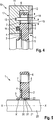
Nachfolgend wird unter Bezugnahme auf die
Am Grundkörper
Ferner sind im Druckring
Im Betrieb dichtet der Dichtring
Um möglichst gute chemische Eigenschaften und eine hohe Verschleißfestigkeit aufzuweisen, ist der einstückige Dichtring
Somit kann erfindungsgemäß mit einem einzigen Bauteil mit einer Lippendichtung
Die Lippendichtung
Durch das Vorsehen des separaten Gleitlagerrings
Wie aus
BezugszeichenlisteLIST OF REFERENCE NUMBERS
- 11
- Dichtringseal
- 22
- Grundkörperbody
- 33
- Lippendichtunglip seal
- 44
- Schlitzslot
- 55
- Gleitlagerflächefriction bearing surface
- 66
- Öffnungenopenings
- 77
- erste große Fasefirst big chamfer
- 88th
- zweite große Fasesecond big chamfer
- 1010
- Baugruppemodule
- 1111
- Aufnahmeadmission
- 1212
- Scheibedisc
- 1313
- Stiftpen
- 1414
- SekundärdichtelementSecondary sealing element
- 15, 1615, 16
- radiales Spielradial play
- 1717
- Gehäusecasing
- 2020
- rotierendes Bauteilrotating component
- 2121
- Spaltgap
- 2222
- ringförmige Ausnehmungannular recess
- 2323
- Wellenhülseshaft sleeve
- 3030
- separater Gleitlagerringseparate slide bearing ring
- 3131
- Gleitflächesliding surface
- 4040
- Patronenanordnungcartridge assembly
- 4141
- Wälzlagerroller bearing
- 4242
- Patronengehäusecartridge housing
- 43, 4443, 44
- Fluidanschlußfluid port
- 5151
- erste Fasefirst phase
- 5252
- zweite Fasesecond phase
- FF
- EigenspannungResidual stress
- KK
- KontaktContact
- RR
- Radialrichtungradial direction
- X-XX X
- Axialrichtungaxially
Claims (12)
Priority Applications (6)
| Application Number | Priority Date | Filing Date | Title |
|---|---|---|---|
| DE102012018652.5A DE102012018652B4 (en) | 2012-09-20 | 2012-09-20 | Cartridge assembly with sealing ring and agitator with such a cartridge assembly |
| CN201380049257.XA CN104662315B (en) | 2012-09-20 | 2013-09-16 | Sealing ring, and sealing cartridge having such a sealing ring |
| PCT/EP2013/002776 WO2014044376A2 (en) | 2012-09-20 | 2013-09-16 | Sealing ring, and sealing cartridge having such a sealing ring |
| IN1956DEN2015 IN2015DN01956A (en) | 2012-09-20 | 2013-09-16 | |
| ES13782957T ES2769456T3 (en) | 2012-09-20 | 2013-09-16 | Shaker unit with sealing ring |
| EP13782957.8A EP2898231B1 (en) | 2012-09-20 | 2013-09-16 | Agitator comprising a sealing ring |
Applications Claiming Priority (1)
| Application Number | Priority Date | Filing Date | Title |
|---|---|---|---|
| DE102012018652.5A DE102012018652B4 (en) | 2012-09-20 | 2012-09-20 | Cartridge assembly with sealing ring and agitator with such a cartridge assembly |
Publications (2)
| Publication Number | Publication Date |
|---|---|
| DE102012018652A1 DE102012018652A1 (en) | 2014-04-10 |
| DE102012018652B4 true DE102012018652B4 (en) | 2016-03-10 |
Family
ID=49486429
Family Applications (1)
| Application Number | Title | Priority Date | Filing Date |
|---|---|---|---|
| DE102012018652.5A Active DE102012018652B4 (en) | 2012-09-20 | 2012-09-20 | Cartridge assembly with sealing ring and agitator with such a cartridge assembly |
Country Status (6)
| Country | Link |
|---|---|
| EP (1) | EP2898231B1 (en) |
| CN (1) | CN104662315B (en) |
| DE (1) | DE102012018652B4 (en) |
| ES (1) | ES2769456T3 (en) |
| IN (1) | IN2015DN01956A (en) |
| WO (1) | WO2014044376A2 (en) |
Citations (7)
| Publication number | Priority date | Publication date | Assignee | Title |
|---|---|---|---|---|
| DE3707913A1 (en) * | 1986-03-24 | 1987-10-08 | Zahnradfabrik Friedrichshafen | SEALING ARRANGEMENT FOR ROTATING MACHINE PARTS |
| DE19712324A1 (en) * | 1997-03-24 | 1998-10-01 | Renner Gmbh | Circulation pump or agitator for heated chemical solutions |
| DE69432508T2 (en) * | 1993-11-23 | 2003-11-13 | Sarcos Group | Volumetric pump and valve |
| US20070182105A1 (en) * | 2006-01-26 | 2007-08-09 | Garlock Sealing Technologies, Llc. A Delaware Corporation | Seal configuration |
| DE102006055298A1 (en) * | 2006-11-23 | 2008-06-05 | Elringklinger Ag | sealing arrangement |
| DE202009013547U1 (en) * | 2009-10-07 | 2010-05-06 | Interseal Dipl.-Ing. Rolf Schmitz Gmbh | Throttle and scraper on shaft passage |
| JP2010175020A (en) * | 2009-01-30 | 2010-08-12 | Starlite Co Ltd | Bearing device with sealing function |
Family Cites Families (6)
| Publication number | Priority date | Publication date | Assignee | Title |
|---|---|---|---|---|
| DE3765249D1 (en) * | 1986-03-24 | 1990-10-31 | Zahnradfabrik Friedrichshafen | SEALING RING FOR ARRANGEMENT BETWEEN AXIAL AND ROTATING MACHINE PARTS. |
| US5303935A (en) * | 1992-02-03 | 1994-04-19 | Saksun Holdings Limited | Fluid seal |
| US5897119A (en) * | 1997-04-18 | 1999-04-27 | Garlock, Inc. | Floating wiper seal assembly |
| US7963526B2 (en) * | 2007-05-15 | 2011-06-21 | Freudenberg-Nok General Partnership | Prelubricated multi-lipped radial shaft seal with large radial offset accommodation |
| KR100819726B1 (en) * | 2007-10-31 | 2008-04-08 | 주식회사 제일정공 | The stuffing box to environment for prevention contamination wasteful engine-oil |
| CN101878388B (en) * | 2007-11-28 | 2014-03-12 | Skf公司 | Seal |
-
2012
- 2012-09-20 DE DE102012018652.5A patent/DE102012018652B4/en active Active
-
2013
- 2013-09-16 WO PCT/EP2013/002776 patent/WO2014044376A2/en unknown
- 2013-09-16 ES ES13782957T patent/ES2769456T3/en active Active
- 2013-09-16 IN IN1956DEN2015 patent/IN2015DN01956A/en unknown
- 2013-09-16 CN CN201380049257.XA patent/CN104662315B/en active Active
- 2013-09-16 EP EP13782957.8A patent/EP2898231B1/en active Active
Patent Citations (7)
| Publication number | Priority date | Publication date | Assignee | Title |
|---|---|---|---|---|
| DE3707913A1 (en) * | 1986-03-24 | 1987-10-08 | Zahnradfabrik Friedrichshafen | SEALING ARRANGEMENT FOR ROTATING MACHINE PARTS |
| DE69432508T2 (en) * | 1993-11-23 | 2003-11-13 | Sarcos Group | Volumetric pump and valve |
| DE19712324A1 (en) * | 1997-03-24 | 1998-10-01 | Renner Gmbh | Circulation pump or agitator for heated chemical solutions |
| US20070182105A1 (en) * | 2006-01-26 | 2007-08-09 | Garlock Sealing Technologies, Llc. A Delaware Corporation | Seal configuration |
| DE102006055298A1 (en) * | 2006-11-23 | 2008-06-05 | Elringklinger Ag | sealing arrangement |
| JP2010175020A (en) * | 2009-01-30 | 2010-08-12 | Starlite Co Ltd | Bearing device with sealing function |
| DE202009013547U1 (en) * | 2009-10-07 | 2010-05-06 | Interseal Dipl.-Ing. Rolf Schmitz Gmbh | Throttle and scraper on shaft passage |
Also Published As
| Publication number | Publication date |
|---|---|
| CN104662315B (en) | 2017-02-22 |
| ES2769456T3 (en) | 2020-06-25 |
| DE102012018652A1 (en) | 2014-04-10 |
| WO2014044376A2 (en) | 2014-03-27 |
| CN104662315A (en) | 2015-05-27 |
| EP2898231B1 (en) | 2019-11-06 |
| WO2014044376A3 (en) | 2014-05-15 |
| EP2898231A2 (en) | 2015-07-29 |
| IN2015DN01956A (en) | 2015-08-07 |
Similar Documents
| Publication | Publication Date | Title |
|---|---|---|
| EP2063157B1 (en) | Mechanical seal arrangement | |
| DE102016101795B4 (en) | Seal arrangements and related processes | |
| DE112007001500T5 (en) | Bearing arrangement with an elastic seal | |
| DE202008003418U1 (en) | Double seal arrangement | |
| EP2457003A1 (en) | Rotating union for oil | |
| EP3728910B1 (en) | Seal assembly | |
| EP2561255B1 (en) | Slip ring seal | |
| DE202005006553U1 (en) | Radial shaft seal comprises membrane and support ring with centering section on its outer rim which press-fits into seal mounting and has wedge-shaped support section on its inner rim | |
| DE102019200371A1 (en) | Rolling bearings, in particular for a medical or cosmetic instrument | |
| DE102012018652B4 (en) | Cartridge assembly with sealing ring and agitator with such a cartridge assembly | |
| EP1818579B1 (en) | Scraping arrangement | |
| DE19841123B4 (en) | Radial shaft seal | |
| DE102010024291B4 (en) | Mechanical seal with rotating counter ring with precisely defined clamping | |
| WO2018149745A1 (en) | Seal arrangement with improved lubrication behavior | |
| EP3504467B1 (en) | Seal assembly and valve assembly | |
| WO2009077027A1 (en) | Slide ring seal arrangement | |
| WO2015172774A1 (en) | Sealing assembly | |
| DE102015215512A1 (en) | Pressure cylinder unit, such as clutch master cylinder, with conically shaped support ring | |
| DE102005037568A1 (en) | Elastomer shaft seal | |
| DE102021213007B3 (en) | SLOTTED GUIDE RING WITH CIRCULATING LUBRICATION AND PISTON-CYLINDER UNIT WITH SUCH | |
| EP1336779A1 (en) | Secoundary sealing element for a mechanical seal | |
| DE102011004707B4 (en) | sealing arrangement | |
| WO2013087068A2 (en) | Sealing device | |
| DE102017128937B4 (en) | Rolling bearing with integrated pressure seal | |
| DE10154788B4 (en) | Shaft seal |
Legal Events
| Date | Code | Title | Description |
|---|---|---|---|
| R012 | Request for examination validly filed | ||
| R016 | Response to examination communication | ||
| R018 | Grant decision by examination section/examining division | ||
| R079 | Amendment of ipc main class |
Free format text: PREVIOUS MAIN CLASS: F16J0015320000 Ipc: F16J0015322800 |
|
| R020 | Patent grant now final |