EP2273638B1 - Pince pour canaux de câble destinée à masquer des bords de coupe - Google Patents
Pince pour canaux de câble destinée à masquer des bords de coupe Download PDFInfo
- Publication number
- EP2273638B1 EP2273638B1 EP10006229.8A EP10006229A EP2273638B1 EP 2273638 B1 EP2273638 B1 EP 2273638B1 EP 10006229 A EP10006229 A EP 10006229A EP 2273638 B1 EP2273638 B1 EP 2273638B1
- Authority
- EP
- European Patent Office
- Prior art keywords
- guide
- bracket according
- cable duct
- fastening
- front plate
- Prior art date
- Legal status (The legal status is an assumption and is not a legal conclusion. Google has not performed a legal analysis and makes no representation as to the accuracy of the status listed.)
- Active
Links
Images


Classifications
-
- H—ELECTRICITY
- H02—GENERATION; CONVERSION OR DISTRIBUTION OF ELECTRIC POWER
- H02G—INSTALLATION OF ELECTRIC CABLES OR LINES, OR OF COMBINED OPTICAL AND ELECTRIC CABLES OR LINES
- H02G3/00—Installations of electric cables or lines or protective tubing therefor in or on buildings, equivalent structures or vehicles
- H02G3/02—Details
- H02G3/04—Protective tubing or conduits, e.g. cable ladders or cable troughs
- H02G3/0406—Details thereof
- H02G3/0418—Covers or lids; Their fastenings
-
- H—ELECTRICITY
- H02—GENERATION; CONVERSION OR DISTRIBUTION OF ELECTRIC POWER
- H02G—INSTALLATION OF ELECTRIC CABLES OR LINES, OR OF COMBINED OPTICAL AND ELECTRIC CABLES OR LINES
- H02G3/00—Installations of electric cables or lines or protective tubing therefor in or on buildings, equivalent structures or vehicles
- H02G3/02—Details
- H02G3/04—Protective tubing or conduits, e.g. cable ladders or cable troughs
- H02G3/0425—Plinths
-
- H—ELECTRICITY
- H02—GENERATION; CONVERSION OR DISTRIBUTION OF ELECTRIC POWER
- H02G—INSTALLATION OF ELECTRIC CABLES OR LINES, OR OF COMBINED OPTICAL AND ELECTRIC CABLES OR LINES
- H02G3/00—Installations of electric cables or lines or protective tubing therefor in or on buildings, equivalent structures or vehicles
- H02G3/02—Details
- H02G3/06—Joints for connecting lengths of protective tubing or channels, to each other or to casings, e.g. to distribution boxes; Ensuring electrical continuity in the joint
- H02G3/0608—Joints for connecting non cylindrical conduits, e.g. channels
Definitions
- the present invention relates to a clamp for cable ducts for lamination of cut edges according to the preamble of claim 1.
- the first type of staples is used for Thomaskasch michmaschine the cut edges of two abutting cable duct sections.
- the second type is used to conceal, ie cover, the end faces of the cable ducts.
- the second type again differentiates between brackets for concealing the left end side of the cable channel, (left side end caps), and brackets for laminating the right end side of the cable channel (right side end caps).
- Such devices for Thomaskasch réelle for cable ducts are for example in the DE 20 2007 006 989 U1 . DE 234 77 94 A1 . DE 295 108 36 U1 as well as in the US 5,469,893 A described.
- a clamp for cable ducts for Thomaskasch ist of cut edges of abutting cable duct sections and / or their ends comprising a strip-shaped front panel with upper and lower locking elements for fastening the clip to a cable duct or cable channel, wherein at the Inside of the front panel at least one guide or fastening element for receiving a separate side panel is formed.
- the clip according to the invention has the advantage that it can be used on the one hand without side panel as Thomaskaschtechnik of cut edges of abutting cable sections and on the other hand together with a side panel for lamination of the ends of a cable channel. This reduces the number of staple types necessary to mount a conduit system.
- two guide fasteners are symmetrically arranged on the inside of the front panel, in which the separate side panel is used at least for a left or right side completion of a cable duct section.
- the clip according to the invention it is possible for the clip according to the invention to be used both as a closure for a left-side and right-side housing section, i. as a left-side or right-side end cap can be used.
- a tapered guide or fastening web is formed at the head end of the side panel.
- the guide or mounting bar allows easy attachment of the side panel to the front panel.
- the side panel is glued to the guide or fastener to the front panel, welded, soldered, locked, screwed or jammed, whereby in a simple manner a stable end cap for a cable duct end is made.
- the guiding or fastening elements consist of a double wall with a central groove.
- the guide or attachment web of the side panel can be inserted or pushed into the central groove and easily attached to the guide or fastener.
- the guide or fastening web has a trapezoidal retaining profile and the groove is undercut trapezoidal on the back. In this way, the side panel without additional fasteners on the front panel can be fastened.
- lugs are formed on the inside of the front panel, which cooperate positively with prottgenauen openings on the underside of the side panel. This allows an additional and thus very secure attachment of the side panel on the front panel.
- the lugs are formed in two rows, so that the side panel is mutually usable for a left or right side completion of a cable duct section. This ensures that an end cap according to the invention has a secure connection between the side panel and the front panel both for the right and the left side use.
- the front panel comprises an angled hood at the head end.
- the guide or fastener may be formed integrally with the hood, for example. In this way, a particularly simple production of the clip according to the invention is possible.
- a cable channel which comprises a lower part and an upper part, wherein for the Thomaskaschierung successive abutting cable duct sections or at the ends of a clamp according to the invention is mounted.
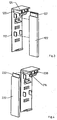
- Fig. 1 shows a clip 10 for cable ducts for Thomaskaschtechnik of cut edges of abutting cable duct sections and / or their ends.
- the clip 10 comprises a strip-shaped front panel 12 with an upper latching lug 14 and a lower latching lug 16 for fastening the clip 10 to a in the FIGS. 5 to 7 illustrated cable channel 18th
- two guide or fastening elements 20 are formed for receiving a separate side panel 22.
- the two guide or fastening elements 20 are arranged symmetrically, so that the side panel 22 can be used both for a left- or right-side termination of a cable duct section.
- Each guide or fastener 20 consists of a double wall with a central groove 24, wherein each guide or fastener 20 is arranged so that the groove 24 is oriented substantially perpendicular to the front panel 12. Furthermore, at one end of the front panel 10 perpendicular to the front panel 12, a hood 26 is fixedly connected to the front panel 12. The guide or fasteners 20 are also firmly connected to the hood 26. In the illustrated embodiment, the guide or fasteners 20 are integrally formed with the hood.
- the upper detent element 14 is arranged between the two guiding or fastening elements 20 and fastened to the lower longitudinal side of the respective inner double wall of the guide or fastening elements 20.
- 12 lugs 28, 30 are formed on the front panel.
- the lugs 28, 30 are arranged in pairs in the embodiment shown.
- the side panel 22 has at its head end a tapered guide or fastening web 32.
- the guide or fastening web 32 is formed so that it can be inserted into the groove 24 of a guide or fastener 20.
- For attaching the sobtende 22 to the guide or fastener 12 of the guide or fastening web 32 can be glued or clamped in the groove 24 with the guide or fastener.
- the side panel 22 has two openings 36 and 38 on its underside 34.
- Each opening 36 is designed so that it can accommodate a nose 28, 30 fit exactly. In this way, the side panel 22 can be additionally attached to the front panel 12.
- Fig. 3 shows a second embodiment of the present invention, which differs from the first embodiment in that the groove 124 of the guide or fastener 120 is trapezoidal undercut at its rear side.
- the side panel 122 has a guiding or fastening web 132 with a trapezoidal retaining profile.
- the guiding or fastening web 132 of the side panel 122 can be pushed into the groove 124 of the front panel 112. In this arrangement, falling out of the side panel 122, in particular the guide or fastening web 132, is prevented from the groove 124 down.
- Fig. 4 shows a third embodiment of the present invention, which differs from the two previous embodiments in that the guide or fastening web 232 is attached to an outer wall 234 of a guiding or fastening element 220.
- the side panel 222 in particular the guiding or fastening web 232, can be glued to the outer wall 234 of the guiding or fastening element 220.
- a locking device may be provided.
- the clip 10 may be used for laminating cut edges of abutting cable duct sections. If the clip is to serve as an end cap for a right side or left side termination of a cable duct section, the side panel will be in one of the above illustrated ways and ways connected to the front panel and attached to this. In this case, the symmetrical arrangement of the two guiding or fastening elements makes it possible for a clamp to be used to produce both a left-side and a right-side end cap.
- Fig. 5 the use of the clip according to the invention is shown as a right-side end cap.
- Fig. 6 shows the clip according to the invention in its function as a left-side end cap and
- Fig. 7 represents the clip according to the invention as Thomaskaschtechnik of a cutting edge of abutting cable channel sections 18.
- the guide or attachment web can be attached to the guide or fastener.
- this list is not exhaustive.
- the guide or fastening web it is also possible, for example, for the guide or fastening web to be welded, soldered, latched, screwed or clamped to the guide or fastening element in order to form a right-hand or left-hand end cap.
- the side panel is mirrored on at least one side or provided with a predefined color.
Landscapes
- Engineering & Computer Science (AREA)
- Architecture (AREA)
- Civil Engineering (AREA)
- Structural Engineering (AREA)
- Installation Of Indoor Wiring (AREA)
Claims (11)
- Attache pour caniveaux de câbles destinée à masquer les bords de coupe de tronçons de caniveau de câbles qui se touchent et/ou leurs extrémités, comprenant :- un cache avant (12 ; 112) en forme de barrette avec des éléments d'encliquetage supérieur et inférieur (14, 16) pour fixer l'attache sur un conduit de câbles ou un caniveau de câbles (18),caractérisée en ce qu'au moins un élément (20 ; 120 ; 220) de guidage ou de fixation est formé sur le côté intérieur du cache avant (12 ; 112) pour recevoir un cache latéral séparé (22 ; 122 ; 222).
- Attache selon la revendication 1, caractérisée en ce que deux éléments (20 ; 120 ; 220) de guidage ou de fixation sont disposés symétriquement sur le côté intérieur du cache avant (12 ; 112), éléments dans lesquels le cache latéral séparé (22 ; 122 ; 222) peut être alternativement installé pour une terminaison à gauche ou à droite d'un tronçon de caniveau de câbles.
- Attache selon la revendication 1 ou 2, caractérisée en ce qu'une nervure rétrécie (32 ; 132 ; 232) de guidage ou de fixation est formée à l'extrémité de tête du cache latéral (22 ; 122 ; 222).
- Attache selon l'une des revendications 1 à 3, caractérisée en ce que le cache latéral (22 ; 122 ; 222) est assemblé par collage, soudage, brasage, encliquetage, vissage ou serrage au cache avant (12 ; 112) au niveau de l'élément (20 ; 120 ; 220) de guidage ou de fixation.
- Attache selon l'une des revendications 1 à 4, caractérisée en ce que les éléments (20 ; 120 ; 220) de guidage ou de fixation sont constitués d'une paroi double avec une rainure centrale (24 ; 124).
- Attache selon l'une des revendications 4 ou 5, caractérisée en ce que la nervure (132) de guidage ou de fixation possède un profil de maintien trapézoïdal, et la rainure (124) est contre-dépouillée en forme de trapèze sur le côté arrière.
- Attache selon la revendication 6, caractérisée en ce que des ergots (28, 30) sont formés sur le côté intérieur du cache avant (12; 112), qui coopèrent en engagement positif avec des ouvertures ajustées (36, 38) sur le dessous du cache latéral (22 ; 122 ; 222).
- Attache selon la revendication 7, caractérisée en ce que les ergots (28, 30) sont formés en deux rangées, de sorte que le cache latéral (22 ; 122 ; 222) peut être utilisé alternativement pour une terminaison à gauche ou à droite d'un tronçon de caniveau de câbles.
- Attache selon l'une des revendications 1 à 8, caractérisée en ce que le cache avant (12 ; 112) comprend à l'extrémité de tête une calotte recourbée (26).
- Attache selon l'une des revendications 1 à 9, caractérisée en ce que le cache latéral (22 ; 122 ; 222) est pourvu d'une couche réfléchissante sur au moins un côté.
- Caniveau de câbles, comprenant une partie inférieure et une partie supérieure, caractérisé en ce qu'une attache selon l'une des revendications 1 à 10 est mise en place pour masquer les bords de coupe de tronçons de caniveau de câbles qui se touchent et/ou à leurs extrémités.
Applications Claiming Priority (1)
| Application Number | Priority Date | Filing Date | Title |
|---|---|---|---|
| DE200920009498 DE202009009498U1 (de) | 2009-07-11 | 2009-07-11 | Klammer für Kabelkanäle zur Kaschierung von Schnittkanten |
Publications (3)
| Publication Number | Publication Date |
|---|---|
| EP2273638A2 EP2273638A2 (fr) | 2011-01-12 |
| EP2273638A3 EP2273638A3 (fr) | 2014-10-22 |
| EP2273638B1 true EP2273638B1 (fr) | 2016-04-20 |
Family
ID=43014464
Family Applications (1)
| Application Number | Title | Priority Date | Filing Date |
|---|---|---|---|
| EP10006229.8A Active EP2273638B1 (fr) | 2009-07-11 | 2010-06-16 | Pince pour canaux de câble destinée à masquer des bords de coupe |
Country Status (2)
| Country | Link |
|---|---|
| EP (1) | EP2273638B1 (fr) |
| DE (1) | DE202009009498U1 (fr) |
Families Citing this family (4)
| Publication number | Priority date | Publication date | Assignee | Title |
|---|---|---|---|---|
| DE202011005060U1 (de) | 2011-04-08 | 2013-12-16 | Tehalit Gmbh | Montagesystem zur Verschiebesicherung und Schnittkaschierung von Oberteilen und Elektroinstallationsgeräten bei Leitungsführungskanälen |
| DE102011052554B4 (de) * | 2011-08-10 | 2022-09-08 | HELLA GmbH & Co. KGaA | Blendenbauteil, Blende und Verfahren zur Herstellung einer mehrteiligen Blende |
| DE202011107458U1 (de) | 2011-11-04 | 2013-02-05 | Tehalit Gmbh | Leitungsführungskanal aus Metall mit Haube zur Schnittkaschierung |
| DE102012025532A1 (de) * | 2011-12-22 | 2013-06-27 | Bachmann Technology GmbH & Co. KG | Endkappe; Befestigungssystem zur Befestigung eines Profilgehäuses in einem Schranksystem; Verfahren zur Befestigung eines Profilgehäuses in einem Schranksystem |
Family Cites Families (8)
| Publication number | Priority date | Publication date | Assignee | Title |
|---|---|---|---|---|
| DE2347794A1 (de) | 1973-09-22 | 1975-04-10 | Beton & Monierbau Ag | Befestigungsvorrichtung fuer schienen auf schwellen mit moeglichem spurausgleich |
| US5469893A (en) | 1993-12-21 | 1995-11-28 | Panduit Corp. | Tab and slot fiber optic fitting |
| DE29510836U1 (de) | 1995-07-04 | 1995-10-12 | Ackermann Albert Gmbh Co | Elektroinstallationskanal |
| US5802672A (en) * | 1996-11-20 | 1998-09-08 | Rohder; Brian K. | Wiring duct end cap |
| FR2820553B1 (fr) * | 2001-02-05 | 2003-07-25 | Legrand Sa | Accessoire pour goulotte et ensemble comprenant un tel accessoire et une goulotte dont le socle est specialement adapte audit accessoire |
| FR2832260B1 (fr) * | 2001-11-15 | 2004-11-19 | Legrand Sa | Accessoire pour goulotte comportant des moyens de collage sur un troncon de couvercle |
| DE202007006989U1 (de) | 2007-05-15 | 2008-09-18 | Tehalit Gmbh | Schnittkaschierung für Kabelkanäle |
| US7544893B2 (en) * | 2007-07-25 | 2009-06-09 | Thomas & Betts International, Inc. | Extruded wire duct end cap |
-
2009
- 2009-07-11 DE DE200920009498 patent/DE202009009498U1/de not_active Expired - Lifetime
-
2010
- 2010-06-16 EP EP10006229.8A patent/EP2273638B1/fr active Active
Also Published As
| Publication number | Publication date |
|---|---|
| EP2273638A3 (fr) | 2014-10-22 |
| DE202009009498U1 (de) | 2010-11-25 |
| EP2273638A2 (fr) | 2011-01-12 |
Similar Documents
| Publication | Publication Date | Title |
|---|---|---|
| EP1980361B1 (fr) | Elément de raccordement et revêtement de protection | |
| DE10340571B3 (de) | Klemme zum Halten von flachen Gegenständen | |
| DE102017108320B4 (de) | Flachteilhalter für die Befestigung eines Flachteils an einem Rahmengestell eines Schaltschranks und ein entsprechender Schaltschrank | |
| EP2273638B1 (fr) | Pince pour canaux de câble destinée à masquer des bords de coupe | |
| EP2012390B1 (fr) | Pince de mise à la terre destinée à l'équilibrage du potentiel de canaux de câblage | |
| DE2807942C2 (de) | Auskleidung für Decken oder Wände, insbesondere für Fassaden | |
| EP2514287A2 (fr) | Unité modulaire | |
| EP3071896B1 (fr) | Support de montage pour une enceinte et méthode de monter une enceinte utilisant ledit support | |
| DE102017124413A1 (de) | Bohrschablone und Verfahren zum Markieren oder Anbohren zweier Möbelplatten | |
| EP3658787B1 (fr) | Composant moulé, procédé servant à assembler au moins un composant en tôle à un composant moulé, et système de construction d'une tôle | |
| DE102016115402A1 (de) | Vorrichtung zur lösbaren Befestigung einer Fahrzeugeinrichtung | |
| DE102010007320B4 (de) | Haltebügel zur Aufnahme eines Gehäuses und Gehäuse zur Aufnahme in einem Haltebügel | |
| DE102016115404A1 (de) | System zur Festlegung wenigstens eines Wandverkleidungsteils | |
| EP3910155A1 (fr) | Dispositif de protection | |
| DE10340196B4 (de) | Schlossmoduleinrichtung für eine Kraftfahrzeugtür | |
| DE212019000344U1 (de) | Abstandshalter zur Einstellung eines Sollabstandes zwischen zwei Komponenten | |
| DE202018104023U1 (de) | Abstandshalter zur Einstellung eines Sollabstandes zwischen zwei Komponenten | |
| EP2759666A2 (fr) | Élément de profilé | |
| DE102013103594B4 (de) | Halteteil für eine Montageplatte, Türbetätiger-Anordnung und Verfahren zum Montieren einer Türbetätiger-Anordnung | |
| EP3618208A1 (fr) | Conduit de câbles et dispositif de raccordement de sections de conduit de câbles | |
| DE19809902B4 (de) | Außenrückblickspiegel | |
| AT520997A1 (de) | Montagehalter | |
| EP3504385B1 (fr) | Système de fixation d'auvent | |
| EP1867807B1 (fr) | Dispositif d'ouverture de porte | |
| DE102016115410A1 (de) | Sytem zur Festlegung wenigstens eines Wandverkleidungsteils |
Legal Events
| Date | Code | Title | Description |
|---|---|---|---|
| PUAI | Public reference made under article 153(3) epc to a published international application that has entered the european phase |
Free format text: ORIGINAL CODE: 0009012 |
|
| AK | Designated contracting states |
Kind code of ref document: A2 Designated state(s): AL AT BE BG CH CY CZ DE DK EE ES FI FR GB GR HR HU IE IS IT LI LT LU LV MC MK MT NL NO PL PT RO SE SI SK SM TR |
|
| AX | Request for extension of the european patent |
Extension state: BA ME RS |
|
| PUAL | Search report despatched |
Free format text: ORIGINAL CODE: 0009013 |
|
| AK | Designated contracting states |
Kind code of ref document: A3 Designated state(s): AL AT BE BG CH CY CZ DE DK EE ES FI FR GB GR HR HU IE IS IT LI LT LU LV MC MK MT NL NO PL PT RO SE SI SK SM TR |
|
| AX | Request for extension of the european patent |
Extension state: BA ME RS |
|
| RIC1 | Information provided on ipc code assigned before grant |
Ipc: H02G 3/06 20060101ALI20140918BHEP Ipc: H02G 3/04 20060101AFI20140918BHEP |
|
| 17P | Request for examination filed |
Effective date: 20150415 |
|
| RBV | Designated contracting states (corrected) |
Designated state(s): AL AT BE BG CH CY CZ DE DK EE ES FI FR GB GR HR HU IE IS IT LI LT LU LV MC MK MT NL NO PL PT RO SE SI SK SM TR |
|
| GRAP | Despatch of communication of intention to grant a patent |
Free format text: ORIGINAL CODE: EPIDOSNIGR1 |
|
| INTG | Intention to grant announced |
Effective date: 20150616 |
|
| GRAS | Grant fee paid |
Free format text: ORIGINAL CODE: EPIDOSNIGR3 |
|
| GRAP | Despatch of communication of intention to grant a patent |
Free format text: ORIGINAL CODE: EPIDOSNIGR1 |
|
| INTG | Intention to grant announced |
Effective date: 20151106 |
|
| GRAA | (expected) grant |
Free format text: ORIGINAL CODE: 0009210 |
|
| RIN1 | Information on inventor provided before grant (corrected) |
Inventor name: MATTFELDT, THIEMO Inventor name: SCHNURR, RICHARD |
|
| AK | Designated contracting states |
Kind code of ref document: B1 Designated state(s): AL AT BE BG CH CY CZ DE DK EE ES FI FR GB GR HR HU IE IS IT LI LT LU LV MC MK MT NL NO PL PT RO SE SI SK SM TR |
|
| REG | Reference to a national code |
Ref country code: GB Ref legal event code: FG4D Free format text: NOT ENGLISH |
|
| REG | Reference to a national code |
Ref country code: CH Ref legal event code: EP |
|
| REG | Reference to a national code |
Ref country code: AT Ref legal event code: REF Ref document number: 793366 Country of ref document: AT Kind code of ref document: T Effective date: 20160515 |
|
| REG | Reference to a national code |
Ref country code: IE Ref legal event code: FG4D Free format text: LANGUAGE OF EP DOCUMENT: GERMAN |
|
| REG | Reference to a national code |
Ref country code: DE Ref legal event code: R096 Ref document number: 502010011457 Country of ref document: DE |
|
| REG | Reference to a national code |
Ref country code: FR Ref legal event code: PLFP Year of fee payment: 7 |
|
| REG | Reference to a national code |
Ref country code: NL Ref legal event code: FP |
|
| REG | Reference to a national code |
Ref country code: LT Ref legal event code: MG4D |
|
| PG25 | Lapsed in a contracting state [announced via postgrant information from national office to epo] |
Ref country code: LT Free format text: LAPSE BECAUSE OF FAILURE TO SUBMIT A TRANSLATION OF THE DESCRIPTION OR TO PAY THE FEE WITHIN THE PRESCRIBED TIME-LIMIT Effective date: 20160420 Ref country code: PL Free format text: LAPSE BECAUSE OF FAILURE TO SUBMIT A TRANSLATION OF THE DESCRIPTION OR TO PAY THE FEE WITHIN THE PRESCRIBED TIME-LIMIT Effective date: 20160420 Ref country code: NO Free format text: LAPSE BECAUSE OF FAILURE TO SUBMIT A TRANSLATION OF THE DESCRIPTION OR TO PAY THE FEE WITHIN THE PRESCRIBED TIME-LIMIT Effective date: 20160720 Ref country code: FI Free format text: LAPSE BECAUSE OF FAILURE TO SUBMIT A TRANSLATION OF THE DESCRIPTION OR TO PAY THE FEE WITHIN THE PRESCRIBED TIME-LIMIT Effective date: 20160420 |
|
| PG25 | Lapsed in a contracting state [announced via postgrant information from national office to epo] |
Ref country code: SE Free format text: LAPSE BECAUSE OF FAILURE TO SUBMIT A TRANSLATION OF THE DESCRIPTION OR TO PAY THE FEE WITHIN THE PRESCRIBED TIME-LIMIT Effective date: 20160420 Ref country code: LV Free format text: LAPSE BECAUSE OF FAILURE TO SUBMIT A TRANSLATION OF THE DESCRIPTION OR TO PAY THE FEE WITHIN THE PRESCRIBED TIME-LIMIT Effective date: 20160420 Ref country code: PT Free format text: LAPSE BECAUSE OF FAILURE TO SUBMIT A TRANSLATION OF THE DESCRIPTION OR TO PAY THE FEE WITHIN THE PRESCRIBED TIME-LIMIT Effective date: 20160822 Ref country code: HR Free format text: LAPSE BECAUSE OF FAILURE TO SUBMIT A TRANSLATION OF THE DESCRIPTION OR TO PAY THE FEE WITHIN THE PRESCRIBED TIME-LIMIT Effective date: 20160420 Ref country code: GR Free format text: LAPSE BECAUSE OF FAILURE TO SUBMIT A TRANSLATION OF THE DESCRIPTION OR TO PAY THE FEE WITHIN THE PRESCRIBED TIME-LIMIT Effective date: 20160721 Ref country code: ES Free format text: LAPSE BECAUSE OF FAILURE TO SUBMIT A TRANSLATION OF THE DESCRIPTION OR TO PAY THE FEE WITHIN THE PRESCRIBED TIME-LIMIT Effective date: 20160420 |
|
| PG25 | Lapsed in a contracting state [announced via postgrant information from national office to epo] |
Ref country code: BE Free format text: LAPSE BECAUSE OF NON-PAYMENT OF DUE FEES Effective date: 20160630 |
|
| REG | Reference to a national code |
Ref country code: DE Ref legal event code: R097 Ref document number: 502010011457 Country of ref document: DE |
|
| PG25 | Lapsed in a contracting state [announced via postgrant information from national office to epo] |
Ref country code: MC Free format text: LAPSE BECAUSE OF FAILURE TO SUBMIT A TRANSLATION OF THE DESCRIPTION OR TO PAY THE FEE WITHIN THE PRESCRIBED TIME-LIMIT Effective date: 20160420 Ref country code: CZ Free format text: LAPSE BECAUSE OF FAILURE TO SUBMIT A TRANSLATION OF THE DESCRIPTION OR TO PAY THE FEE WITHIN THE PRESCRIBED TIME-LIMIT Effective date: 20160420 Ref country code: EE Free format text: LAPSE BECAUSE OF FAILURE TO SUBMIT A TRANSLATION OF THE DESCRIPTION OR TO PAY THE FEE WITHIN THE PRESCRIBED TIME-LIMIT Effective date: 20160420 Ref country code: RO Free format text: LAPSE BECAUSE OF FAILURE TO SUBMIT A TRANSLATION OF THE DESCRIPTION OR TO PAY THE FEE WITHIN THE PRESCRIBED TIME-LIMIT Effective date: 20160420 Ref country code: DK Free format text: LAPSE BECAUSE OF FAILURE TO SUBMIT A TRANSLATION OF THE DESCRIPTION OR TO PAY THE FEE WITHIN THE PRESCRIBED TIME-LIMIT Effective date: 20160420 Ref country code: SK Free format text: LAPSE BECAUSE OF FAILURE TO SUBMIT A TRANSLATION OF THE DESCRIPTION OR TO PAY THE FEE WITHIN THE PRESCRIBED TIME-LIMIT Effective date: 20160420 |
|
| REG | Reference to a national code |
Ref country code: CH Ref legal event code: PL |
|
| PLBE | No opposition filed within time limit |
Free format text: ORIGINAL CODE: 0009261 |
|
| STAA | Information on the status of an ep patent application or granted ep patent |
Free format text: STATUS: NO OPPOSITION FILED WITHIN TIME LIMIT |
|
| PG25 | Lapsed in a contracting state [announced via postgrant information from national office to epo] |
Ref country code: SM Free format text: LAPSE BECAUSE OF FAILURE TO SUBMIT A TRANSLATION OF THE DESCRIPTION OR TO PAY THE FEE WITHIN THE PRESCRIBED TIME-LIMIT Effective date: 20160420 |
|
| GBPC | Gb: european patent ceased through non-payment of renewal fee |
Effective date: 20160720 |
|
| REG | Reference to a national code |
Ref country code: IE Ref legal event code: MM4A |
|
| 26N | No opposition filed |
Effective date: 20170123 |
|
| PG25 | Lapsed in a contracting state [announced via postgrant information from national office to epo] |
Ref country code: CH Free format text: LAPSE BECAUSE OF NON-PAYMENT OF DUE FEES Effective date: 20160630 Ref country code: LI Free format text: LAPSE BECAUSE OF NON-PAYMENT OF DUE FEES Effective date: 20160630 |
|
| PG25 | Lapsed in a contracting state [announced via postgrant information from national office to epo] |
Ref country code: SI Free format text: LAPSE BECAUSE OF FAILURE TO SUBMIT A TRANSLATION OF THE DESCRIPTION OR TO PAY THE FEE WITHIN THE PRESCRIBED TIME-LIMIT Effective date: 20160420 Ref country code: GB Free format text: LAPSE BECAUSE OF NON-PAYMENT OF DUE FEES Effective date: 20160720 Ref country code: IE Free format text: LAPSE BECAUSE OF NON-PAYMENT OF DUE FEES Effective date: 20160616 |
|
| REG | Reference to a national code |
Ref country code: FR Ref legal event code: PLFP Year of fee payment: 8 |
|
| REG | Reference to a national code |
Ref country code: AT Ref legal event code: MM01 Ref document number: 793366 Country of ref document: AT Kind code of ref document: T Effective date: 20160616 |
|
| PG25 | Lapsed in a contracting state [announced via postgrant information from national office to epo] |
Ref country code: AT Free format text: LAPSE BECAUSE OF NON-PAYMENT OF DUE FEES Effective date: 20160616 |
|
| PG25 | Lapsed in a contracting state [announced via postgrant information from national office to epo] |
Ref country code: CY Free format text: LAPSE BECAUSE OF FAILURE TO SUBMIT A TRANSLATION OF THE DESCRIPTION OR TO PAY THE FEE WITHIN THE PRESCRIBED TIME-LIMIT Effective date: 20160420 Ref country code: HU Free format text: LAPSE BECAUSE OF FAILURE TO SUBMIT A TRANSLATION OF THE DESCRIPTION OR TO PAY THE FEE WITHIN THE PRESCRIBED TIME-LIMIT; INVALID AB INITIO Effective date: 20100616 |
|
| REG | Reference to a national code |
Ref country code: FR Ref legal event code: PLFP Year of fee payment: 9 |
|
| PG25 | Lapsed in a contracting state [announced via postgrant information from national office to epo] |
Ref country code: MT Free format text: LAPSE BECAUSE OF FAILURE TO SUBMIT A TRANSLATION OF THE DESCRIPTION OR TO PAY THE FEE WITHIN THE PRESCRIBED TIME-LIMIT Effective date: 20160420 Ref country code: TR Free format text: LAPSE BECAUSE OF FAILURE TO SUBMIT A TRANSLATION OF THE DESCRIPTION OR TO PAY THE FEE WITHIN THE PRESCRIBED TIME-LIMIT Effective date: 20160420 Ref country code: IS Free format text: LAPSE BECAUSE OF FAILURE TO SUBMIT A TRANSLATION OF THE DESCRIPTION OR TO PAY THE FEE WITHIN THE PRESCRIBED TIME-LIMIT Effective date: 20160420 Ref country code: MK Free format text: LAPSE BECAUSE OF FAILURE TO SUBMIT A TRANSLATION OF THE DESCRIPTION OR TO PAY THE FEE WITHIN THE PRESCRIBED TIME-LIMIT Effective date: 20160420 Ref country code: LU Free format text: LAPSE BECAUSE OF NON-PAYMENT OF DUE FEES Effective date: 20160616 |
|
| PG25 | Lapsed in a contracting state [announced via postgrant information from national office to epo] |
Ref country code: BG Free format text: LAPSE BECAUSE OF FAILURE TO SUBMIT A TRANSLATION OF THE DESCRIPTION OR TO PAY THE FEE WITHIN THE PRESCRIBED TIME-LIMIT Effective date: 20160420 |
|
| PG25 | Lapsed in a contracting state [announced via postgrant information from national office to epo] |
Ref country code: AL Free format text: LAPSE BECAUSE OF FAILURE TO SUBMIT A TRANSLATION OF THE DESCRIPTION OR TO PAY THE FEE WITHIN THE PRESCRIBED TIME-LIMIT Effective date: 20160420 |
|
| P01 | Opt-out of the competence of the unified patent court (upc) registered |
Effective date: 20230606 |
|
| PGFP | Annual fee paid to national office [announced via postgrant information from national office to epo] |
Ref country code: NL Payment date: 20230626 Year of fee payment: 14 Ref country code: FR Payment date: 20230626 Year of fee payment: 14 Ref country code: DE Payment date: 20230626 Year of fee payment: 14 |
|
| PGFP | Annual fee paid to national office [announced via postgrant information from national office to epo] |
Ref country code: IT Payment date: 20230620 Year of fee payment: 14 |