EP2273281B1 - Verfahren zum genauen Verfolgen und Kommunizieren mit einem Satelliten von einer mobilen Plattform - Google Patents
Verfahren zum genauen Verfolgen und Kommunizieren mit einem Satelliten von einer mobilen Plattform Download PDFInfo
- Publication number
- EP2273281B1 EP2273281B1 EP10185844A EP10185844A EP2273281B1 EP 2273281 B1 EP2273281 B1 EP 2273281B1 EP 10185844 A EP10185844 A EP 10185844A EP 10185844 A EP10185844 A EP 10185844A EP 2273281 B1 EP2273281 B1 EP 2273281B1
- Authority
- EP
- European Patent Office
- Prior art keywords
- antenna
- target
- receive
- antenna aperture
- inertial reference
- Prior art date
- Legal status (The legal status is an assumption and is not a legal conclusion. Google has not performed a legal analysis and makes no representation as to the accuracy of the status listed.)
- Expired - Lifetime
Links
- 238000000034 method Methods 0.000 title claims description 64
- 238000012544 monitoring process Methods 0.000 claims 1
- 230000005540 biological transmission Effects 0.000 description 8
- 238000004891 communication Methods 0.000 description 5
- 238000010586 diagram Methods 0.000 description 3
- 230000001133 acceleration Effects 0.000 description 1
- 230000007812 deficiency Effects 0.000 description 1
- 230000002401 inhibitory effect Effects 0.000 description 1
- 238000005259 measurement Methods 0.000 description 1
- 238000005457 optimization Methods 0.000 description 1
- 230000000737 periodic effect Effects 0.000 description 1
- 238000000926 separation method Methods 0.000 description 1
Images


Classifications
-
- G—PHYSICS
- G01—MEASURING; TESTING
- G01S—RADIO DIRECTION-FINDING; RADIO NAVIGATION; DETERMINING DISTANCE OR VELOCITY BY USE OF RADIO WAVES; LOCATING OR PRESENCE-DETECTING BY USE OF THE REFLECTION OR RERADIATION OF RADIO WAVES; ANALOGOUS ARRANGEMENTS USING OTHER WAVES
- G01S3/00—Direction-finders for determining the direction from which infrasonic, sonic, ultrasonic, or electromagnetic waves, or particle emission, not having a directional significance, are being received
- G01S3/02—Direction-finders for determining the direction from which infrasonic, sonic, ultrasonic, or electromagnetic waves, or particle emission, not having a directional significance, are being received using radio waves
- G01S3/14—Systems for determining direction or deviation from predetermined direction
- G01S3/16—Systems for determining direction or deviation from predetermined direction using amplitude comparison of signals derived sequentially from receiving antennas or antenna systems having differently-oriented directivity characteristics or from an antenna system having periodically-varied orientation of directivity characteristic
- G01S3/20—Systems for determining direction or deviation from predetermined direction using amplitude comparison of signals derived sequentially from receiving antennas or antenna systems having differently-oriented directivity characteristics or from an antenna system having periodically-varied orientation of directivity characteristic derived by sampling signal received by an antenna system having periodically-varied orientation of directivity characteristic
-
- H—ELECTRICITY
- H01—ELECTRIC ELEMENTS
- H01Q—ANTENNAS, i.e. RADIO AERIALS
- H01Q1/00—Details of, or arrangements associated with, antennas
- H01Q1/12—Supports; Mounting means
- H01Q1/125—Means for positioning
-
- H—ELECTRICITY
- H01—ELECTRIC ELEMENTS
- H01Q—ANTENNAS, i.e. RADIO AERIALS
- H01Q3/00—Arrangements for changing or varying the orientation or the shape of the directional pattern of the waves radiated from an antenna or antenna system
- H01Q3/02—Arrangements for changing or varying the orientation or the shape of the directional pattern of the waves radiated from an antenna or antenna system using mechanical movement of antenna or antenna system as a whole
- H01Q3/08—Arrangements for changing or varying the orientation or the shape of the directional pattern of the waves radiated from an antenna or antenna system using mechanical movement of antenna or antenna system as a whole for varying two co-ordinates of the orientation
-
- H—ELECTRICITY
- H04—ELECTRIC COMMUNICATION TECHNIQUE
- H04B—TRANSMISSION
- H04B7/00—Radio transmission systems, i.e. using radiation field
- H04B7/14—Relay systems
- H04B7/15—Active relay systems
- H04B7/185—Space-based or airborne stations; Stations for satellite systems
- H04B7/18502—Airborne stations
- H04B7/18506—Communications with or from aircraft, i.e. aeronautical mobile service
- H04B7/18508—Communications with or from aircraft, i.e. aeronautical mobile service with satellite system used as relay, i.e. aeronautical mobile satellite service
Definitions
- the present invention relates to satellite communication systems, and more particularly to a system for use with a mobile platform having an antenna aperture performing receive and transmit functions, and to a method for causing the antenna aperture to accurately track a target satellite while the mobile platform is moving.
- High precision tracking of communication satellites from mobile platforms such as aircraft, ships and land vehicles is required for both optimizing data rate (i.e., peak energy from/to target) and for preventing interference with satellites orbiting adjacent to a target satellite.
- Various methods for tracking have been used including "dead-reckoning" or open-loop, where a calculation is made as to the correct pointing angles based on known satellite and platform positions and platform attitude.
- Other methods such as “closed loop” tracking methods, make use of some form of feedback control by signal optimization. These methods work adequately for received signals but not adequately for transmitted signals from the mobile platform to satellites over distances which create latency in the feedback control loop with respect to the required bandwidth.
- Such a situation would be represented by, for example, geostationary satellites communicating with mobile platforms having high attitude accelerations, such as aircraft and land vehicles.
- Sequential lobing involves steering the antenna aperture deliberately a known distance away from a peak received signal in each of four directions around the peak signal. This is illustrated in Figure 1 . Measurements of the received power or decoded signal are used to calculate where the actual peak of the beam or signal is located, as indicated in Figure 1b , and the beam is recentered for the next cycle.
- a receive-only antenna can use this approach quite effectively to maintain pointing accuracy.
- the deficiency with this approach is that a transmitting antenna slaved to such a receive beam will execute the same step-tracking, inherently adding inaccuracy as the beam is deliberately stepped away from the known center.
- a second technique of antenna pointing relies on increasingly accurate methods of open-loop calculation to maintain accurate pointing. Even if arbitrarily accurate tracking during movement of the mobile platform is possible, the major drawback with this approach is in initially establishing an accurate starting point (i.e., initially determining an accurate estimate of the position of the target satellite relative to the mobile platform).
- Patent 6,002,364 discloses an apparatus and method for beam steering control system of a mobile satellite communications antenna which includes an antenna having a steering mechanism; a dynamic rate sensor for producing a signal the rate of change of a vehicle to which the antenna is mounted; and a control system of controlling the steering mechanism.
- the present invention is directed to a system for more accurately tracking and communicating with a satellite from a mobile platform.
- the system of the present invention is particularly adapted for use with antenna apertures which are required to receive and transmit information to and from a target satellite while the mobile platform which the antenna aperture is mounted on is moving.
- the system of the present invention involves initially requiring the satellite to use the mobile platform's inertial reference unit (IRU) and information stored in an antenna controller associated with the antenna aperture as to the approximate location of the target satellite. Once the signal from the satellite is acquired, a conventional sequential lobing process is performed to more accurately center the antenna aperture relative to the receive beam received by the aperture. Once the sequential lobing process is completed, the antenna can then be used to transmit data or other information from the mobile platform to the satellite. While transmitting, a second inertial reference unit in the form of a "rate gyro" local to the antenna is used instead of the IRU of the aircraft to maintain the antenna aperture pointed at the target satellite.
- IRU inertial reference unit
- the antenna controller interrupts the transmission of data or other information from the antenna to the target satellite and again uses the receive capability of the antenna to perform the sequential lobing process. Once this process is completed, transmissions from the antenna are again enabled, thus allowing the antenna to be used to transmit information to the satellite.
- This process of alternately transmitting from the antenna aperture and inhibiting transmissions while performing the sequential lobing process is repeated continuously to eliminate inertial reference drift error which could otherwise eventually accumulate to an unacceptable level.
- the above-described system does not significantly interfere with the transmission of data or other information from the antenna because the sequential lobing process can be performed in a matter of milliseconds.
- Figures 1a and 1b illustrate a sequential lobing process by which an antenna aperture can be pointed at a beam center of a received beam from a satellite;
- Figure 2 illustrates separate receive and antenna apertures disposed on a mobile platform, with the transmit antenna aperture slaved to the pointing direction of the receive antenna aperture, and the inherent misalignment between the two antenna apertures because of the physical separation thereof on the mobile platform;
- Figure 3 is a simplified diagram of an antenna aperture which performs transmit and receive functions, and illustrating the degree of error present when the pointing accuracy requirement during transmit is smaller than the step size used in the sequential lobing process performed with a receive beam;
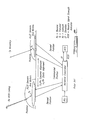
- Figure 4 is a simplified view of a mobile platform having an antenna aperture performing receive and transmit functions in communication with a target satellite;
- Figure 5 is a flowchart illustrating the steps performed in accordance with a preferred method for more accurately acquiring and tracking a target satellite with an antenna aperture performing both transmit and receive functions located on a mobile platform;
- FIG. 6 is a simplified block diagram of a system in accordance with a preferred embodiment of the present invention.
- Figure 7 is a graph illustrating how the method continuously corrects for inertial drift error by periodically performing sequential lobing with the antenna.
- a mobile platform 10 having an antenna aperture 12 in communication with a target satellite 14.
- the antenna aperture 12 is adapted to perform both receive and transmit functions so as to be able to receive signals from the satellite 14, as well as to transmit data and other information to the satellite.
- the satellite 14 typically carries one or more transponders 16 for transponding the signals to a ground station (not shown).
- the mobile platform 10 includes an inertial reference unit (IRU), an antenna controller and a receive/transmit antenna subsystem, as indicated in Figures 2 and 3 , for controlling pointing of the antenna aperture 12.
- IRU inertial reference unit
- Step 5 the method will be described.
- the method involves initially using the IRU of the aircraft 10 to acquire a signal from the satellite 14, as indicated at step 18. This signal is then optimized using the sequential lobing process described in connection with Figure 1 , as indicated at step 20. It will be appreciated that while the sequential lobing process is being performed, the antenna aperture 12 will be operating in a receive-only mode. Step 20 essentially causes the antenna controller of the aircraft 10 to center the antenna aperture 12 relative to the receive beam which it receives from the satellite 14.
- the antenna 12 can be used to begin transmitting data, as indicated at step 22.
- another inertial reference unit in the form of an antenna rate gyro subsystem local to the antenna 12 is used to track the satellite 14 by re-pointing the antenna 12 as needed to maintain the antenna pointed at the satellite 14, as indicated at step 24.
- Step 28 essentially more accurately centers the antenna 12 on the receive beam to eliminate any inertial reference drift error that may have occurred since the initial sequential lobing process was performed at step 20.
- step 30 tracking of the satellite 14 using the antenna rate gyro of the aircraft 10 is resumed, as indicated at step 30.
- This process is repeated, as indicated by feedback line 32, continuously during flight of the aircraft 10.
- steps 26-30 may be performed in a manner of milliseconds while step 24 may be performed for a period of seconds to minutes.
- steps 26-30 may be performed in a manner of milliseconds while step 24 may be performed for a period of seconds to minutes.
- FIG. 6 is a simplified block diagram of a system 34 in accordance with a preferred embodiment of the present invention.
- a motor and sensor subsystem 36 is used to monitor and control antenna positioning.
- a rate gyro subsystem 38 is used to provide inertial reference information used to aim the antenna aperture 40.
- Figure 7 is a graph illustrating the pointing error versus time, and how the periodic, repeated sequential lobing serves to "re-center" the antenna 12.
- Portions 42 of waveform 44 indicate gradually increasing inertial drift error.
- Spikes 46 indicate those very short time periods (typically in milliseconds) during which the transmit function of the antenna 12 is inhibited while sequential lobing is performed to re-center the antenna relative to the receive beam.
- the step c) can be performed for a longer period of time than said sequential lobing process of step b).
- the step c) can comprise the step of transmitting information from said antenna aperture while said antenna rate gyro is being used to maintain said antenna aperture pointed at said target.
- the step c) can be performed for a shorter time period than step a).
- the method can further comprise the step of using said IRU to initially acquire said target before performing said sequential lobing process.
- said sequential lobing process can be performed within a time frame substantially shorter than a time period during which said antenna aperture is used in said transmit-plus-receive mode.
- a method for accurately pointing an antenna aperture performing receive and transmit functions at a target and tracking said target wherein said antenna aperture is disposed on a mobile platform having an inertial reference system (IRU) and said IRU has been used to initially acquire said target, said method comprising the steps of: a) using said antenna aperture in a receive-only mode to perform a sequential lobing process with a receive beam received from said target to center said antenna aperture on said target; and b) when said sequential lobing process is completed, then using an antenna rate gyro to supply information for maintaining said antenna aperture pointed at said target while said antenna aperture used in a transmit-plus-receive mode to transmit information to said target; and c) periodically interrupting transmissions from said antenna aperture to re-perform said sequential lobing process of step a), to thereby maintain said antenna aperture pointed at said target.
- IRU inertial reference system
- said sequential lobing process is performed within a time frame substantially shorter than a time period during which said antenna aperture is in said transmit-plus-receive mode.
- said sequential lobing process is performed in step a) in less than about one second.
Landscapes
- Engineering & Computer Science (AREA)
- Physics & Mathematics (AREA)
- General Physics & Mathematics (AREA)
- Astronomy & Astrophysics (AREA)
- Aviation & Aerospace Engineering (AREA)
- Computer Networks & Wireless Communication (AREA)
- Signal Processing (AREA)
- Radar, Positioning & Navigation (AREA)
- Remote Sensing (AREA)
- Variable-Direction Aerials And Aerial Arrays (AREA)
- Radio Relay Systems (AREA)
- Details Of Aerials (AREA)
Claims (4)
- System (34) zur Verwendung mit einer mobilen Plattform (10), dass aufweist:eine Antenne (12), die zum Durchführen einer Empfangsfunktion und einer Sendefunktion angepasst ist, um sowohl Signale von einem Ziel (14) empfangen zu können als auch Daten und andere Informationen an das Ziel (14) übertragen zu können;einer Inertialreferenzeinheit (IRU);einer zusätzlichen Inertialreferenzeinheit (38);einem Antennen-Kontroller; undeinem Empfangs-/ Sendeantennensubsystem,
dadurch gekennzeichnet, dass die Inertialreferenzeinheit angepasst ist, die Antennenanordnung (40) anfänglich ein Ziel erfassen zu lassen, indem ein sequenzieller Leitstrahl Drehvorgang eingesetzt wird, während die Antennenanordnung (40) eine ausschließlich empfangende Funktion durchführt, um die Antennenanordnung (40) genau relativ zu einem Empfangsstrahl zu zentrieren, der vom Ziel (14) ausgesendet wird, und in dem eine Information der zusätzlichen Inertialreferenzeinheit (38) verwendet wird (24, 30), die sich bei der Antennenanordnung (40) befindet, um das Ziel (14) zu verfolgen, während die Antennenanordnung (40) sendet;und die Übertragung intermittierend zu unterbrechen, um den sequenziellen Leitstrahldrehvorgang erneut durchzuführen, um einen Inertialreferenzdriftfehler zu korrigieren. - System nach Anspruch 1, das einen Motor und ein Sensorsubsystem (36) zum Überwachen und Steuern von Antennenpositionen aufweist.
- Verfahren nach einem der Ansprüche 1 oder 2 wobei die zusätzliche Inertialreferenzeinheit ein Ratenkreiselsubsystem (38) zum Bereitstellen einer Inertialreferenzinformation aufweist, die zum Ausrichten der Antennenanordnung (40) verwendet wird.
- System nach einem der Ansprüche 1 bis 3 wobei die Inertialreferenzeinheit (IRU), der Antennenkontroller und das Empfangs-/Sendeantennensubsystem Teil der mobilen Plattform (10) sind, die wiederum Teil des Systems (34) ist.
Applications Claiming Priority (2)
| Application Number | Priority Date | Filing Date | Title |
|---|---|---|---|
| US09/870,365 US6483458B1 (en) | 2001-05-30 | 2001-05-30 | Method for accurately tracking and communicating with a satellite from a mobile platform |
| EP02774104A EP1399987B1 (de) | 2001-05-30 | 2002-05-13 | Verfahren zum genauen verfolgen und kommunizieren mit einem satelliten von einer mobilen plattform |
Related Parent Applications (1)
| Application Number | Title | Priority Date | Filing Date |
|---|---|---|---|
| EP02774104.0 Division | 2002-05-13 |
Publications (3)
| Publication Number | Publication Date |
|---|---|
| EP2273281A2 EP2273281A2 (de) | 2011-01-12 |
| EP2273281A3 EP2273281A3 (de) | 2011-02-16 |
| EP2273281B1 true EP2273281B1 (de) | 2012-06-27 |
Family
ID=25355226
Family Applications (2)
| Application Number | Title | Priority Date | Filing Date |
|---|---|---|---|
| EP02774104A Expired - Lifetime EP1399987B1 (de) | 2001-05-30 | 2002-05-13 | Verfahren zum genauen verfolgen und kommunizieren mit einem satelliten von einer mobilen plattform |
| EP10185844A Expired - Lifetime EP2273281B1 (de) | 2001-05-30 | 2002-05-13 | Verfahren zum genauen Verfolgen und Kommunizieren mit einem Satelliten von einer mobilen Plattform |
Family Applications Before (1)
| Application Number | Title | Priority Date | Filing Date |
|---|---|---|---|
| EP02774104A Expired - Lifetime EP1399987B1 (de) | 2001-05-30 | 2002-05-13 | Verfahren zum genauen verfolgen und kommunizieren mit einem satelliten von einer mobilen plattform |
Country Status (6)
| Country | Link |
|---|---|
| US (1) | US6483458B1 (de) |
| EP (2) | EP1399987B1 (de) |
| JP (1) | JP4203413B2 (de) |
| CN (1) | CN100373690C (de) |
| AU (1) | AU2002308727A1 (de) |
| WO (1) | WO2002098016A2 (de) |
Families Citing this family (26)
| Publication number | Priority date | Publication date | Assignee | Title |
|---|---|---|---|---|
| US7921442B2 (en) | 2000-08-16 | 2011-04-05 | The Boeing Company | Method and apparatus for simultaneous live television and data services using single beam antennas |
| US6708019B2 (en) * | 2001-04-04 | 2004-03-16 | The Boeing Company | Method and apparatus using transmit beam lobing for identifying an interfering mobile terminal |
| AU2002303571A1 (en) * | 2002-04-30 | 2003-11-17 | The Boeing Company | Beam alignment methods for an antenna |
| KR100588702B1 (ko) * | 2003-05-26 | 2006-06-12 | 기아자동차주식회사 | 이동형 위성추적안테나 시스템의 음영지역제어방법 |
| US7460830B2 (en) * | 2003-12-29 | 2008-12-02 | Peersat, Llc. | Inter-satellite crosslink communications system, apparatus, method and computer program product |
| US8606433B2 (en) * | 2004-01-29 | 2013-12-10 | The Boeing Company | Satellite coverage region detection |
| US7009558B1 (en) * | 2005-03-14 | 2006-03-07 | Delphi Technologies, Inc. | Vehicle mounted satellite tracking system |
| US7218273B1 (en) * | 2006-05-24 | 2007-05-15 | L3 Communications Corp. | Method and device for boresighting an antenna on a moving platform using a moving target |
| KR100798129B1 (ko) * | 2006-09-06 | 2008-02-01 | 위월드 주식회사 | 위성 추적 모드 선택형 위성 안테나 시스템 |
| CN1960056B (zh) * | 2006-09-22 | 2011-07-20 | 中国电子科技集团公司第二十八研究所 | 移动式天线跟踪运动目标的方法及系统 |
| EP2193612B1 (de) | 2007-09-24 | 2011-04-13 | Panasonic Avionics Corporation | Anordnung und verfahren zum empfang eines rundfunkinhalts auf einer mobilen plattform während der reise |
| KR100963200B1 (ko) * | 2007-11-07 | 2010-06-10 | 위월드 주식회사 | 추적 특성이 향상된 위성 추적 안테나 시스템 및 그동작방법 |
| US7843386B2 (en) * | 2008-10-14 | 2010-11-30 | The Boeing Company | System and method for determining the beam center location of an antenna |
| US8509990B2 (en) | 2008-12-15 | 2013-08-13 | Panasonic Avionics Corporation | System and method for performing real-time data analysis |
| WO2010144815A2 (en) | 2009-06-11 | 2010-12-16 | Panasonic Avionics Corporation | System and method for providing security aboard a moving platform |
| US8504217B2 (en) | 2009-12-14 | 2013-08-06 | Panasonic Avionics Corporation | System and method for providing dynamic power management |
| CN103249642B (zh) | 2010-09-10 | 2016-05-25 | 松下航空电子公司 | 集成用户接口系统和方法以及相应的用户座椅、信息系统与飞行器 |
| JP5907535B2 (ja) * | 2013-02-21 | 2016-04-26 | 日本電信電話株式会社 | 衛星追尾アンテナシステムおよび衛星追尾アンテナ制御方法 |
| CA2841685C (en) | 2013-03-15 | 2021-05-18 | Panasonic Avionics Corporation | System and method for providing multi-mode wireless data distribution |
| CN103472849B (zh) * | 2013-09-04 | 2015-10-21 | 航天东方红卫星有限公司 | 基于闭环模式合作目标跟踪的卫星姿态机动跟踪方法 |
| CN105242285B (zh) * | 2015-10-15 | 2017-11-07 | 北京航空航天大学 | 一种基于卫星通信的无人机导航数据被欺骗识别方法 |
| JP6760825B2 (ja) * | 2016-11-11 | 2020-09-23 | 三菱重工業株式会社 | レーダ装置及び航空機 |
| EP3548913B1 (de) | 2016-11-29 | 2023-06-14 | Quadsat IVS | System zum prüfen der genauigkeit der automatischen positionierungsmittel einer signalverfolgungsantenne |
| US11710887B2 (en) * | 2018-05-31 | 2023-07-25 | Kymeta Corporation | Satellite signal acquisition |
| CN111337055B (zh) * | 2020-05-07 | 2023-06-02 | 成都国卫通信技术有限公司 | 一种卫星移动通信天线惯导的标校方法 |
| US11387896B1 (en) | 2021-02-01 | 2022-07-12 | Ses S.A. | Satellite terminal antenna pointing arrangement using separate forward and return satellites |
Family Cites Families (20)
| Publication number | Priority date | Publication date | Assignee | Title |
|---|---|---|---|---|
| US3699324A (en) * | 1970-09-17 | 1972-10-17 | Walter R Iliff | Energy source tracking system employing drift-line technique |
| US4055845A (en) | 1976-06-14 | 1977-10-25 | Ladrick Ray C | Antenna erecting system |
| US4263539A (en) | 1977-10-04 | 1981-04-21 | Zenith Radio Corporation | Automatic antenna positioning apparatus |
| US4542326A (en) | 1982-10-08 | 1985-09-17 | Heath Company | Automatic antenna positioning system |
| US4617567A (en) * | 1984-09-28 | 1986-10-14 | The Boeing Company | Automatic motion compensation for residual motion in a synthetic aperture radar system |
| US4853699A (en) * | 1987-11-13 | 1989-08-01 | Hughes Aircraft Company | Method for cancelling azimuth ambiguity in a SAR receiver |
| US5061936A (en) * | 1989-09-14 | 1991-10-29 | Aisin Seiki K.K. | Attitude control system for mobile antenna |
| US5202695A (en) * | 1990-09-27 | 1993-04-13 | Sperry Marine Inc. | Orientation stabilization by software simulated stabilized platform |
| US5398035A (en) | 1992-11-30 | 1995-03-14 | The United States Of America As Represented By The Administrator Of The National Aeronautics And Space Administration | Satellite-tracking millimeter-wave reflector antenna system for mobile satellite-tracking |
| DE69324771T2 (de) * | 1992-11-30 | 1999-09-09 | All Nippon Airways Co. Ltd. | Mobiler Empfänger für Satellitenfunk |
| FR2700640B1 (fr) * | 1993-01-15 | 1995-02-24 | Thomson Csf | Dispositif de stabilisation du pointage du faisceau d'une antenne à balayage électronique rigidement fixée sur un mobile. |
| US5485156A (en) * | 1994-09-21 | 1996-01-16 | Alliedsignal Inc. | Antenna stabilization error correction system for radar |
| US5917446A (en) * | 1995-11-08 | 1999-06-29 | The Charles Stark Draper Laboratory, Inc. | Radio-wave reception system using inertial data in the receiver beamforming operation |
| US5835057A (en) * | 1996-01-26 | 1998-11-10 | Kvh Industries, Inc. | Mobile satellite communication system including a dual-frequency, low-profile, self-steering antenna assembly |
| US5790175A (en) * | 1996-06-19 | 1998-08-04 | Hughes Aircraft Company | Aircraft satellite television system for distributing television programming derived from direct broadcast satellites |
| KR100199016B1 (ko) * | 1996-12-02 | 1999-06-15 | 정선종 | 차량탑재 안테나 시스템을 위한 위성추적방법 |
| US6002364A (en) * | 1997-07-31 | 1999-12-14 | Cbs Corporation | Apparatus and method for beam steering control system of a mobile satellite communications antenna |
| US5912642A (en) * | 1998-04-28 | 1999-06-15 | Ball Aerospace & Technologies Corp. | Method and system for aligning a sensor on a platform |
| US6400317B2 (en) * | 1998-09-21 | 2002-06-04 | Tantivy Communications, Inc. | Method and apparatus for antenna control in a communications network |
| US6208307B1 (en) * | 2000-04-07 | 2001-03-27 | Live Tv, Inc. | Aircraft in-flight entertainment system having wideband antenna steering and associated methods |
-
2001
- 2001-05-30 US US09/870,365 patent/US6483458B1/en not_active Expired - Lifetime
-
2002
- 2002-05-13 CN CNB028106172A patent/CN100373690C/zh not_active Expired - Lifetime
- 2002-05-13 JP JP2003501090A patent/JP4203413B2/ja not_active Expired - Fee Related
- 2002-05-13 EP EP02774104A patent/EP1399987B1/de not_active Expired - Lifetime
- 2002-05-13 WO PCT/US2002/015336 patent/WO2002098016A2/en not_active Ceased
- 2002-05-13 AU AU2002308727A patent/AU2002308727A1/en not_active Abandoned
- 2002-05-13 EP EP10185844A patent/EP2273281B1/de not_active Expired - Lifetime
Also Published As
| Publication number | Publication date |
|---|---|
| EP1399987A2 (de) | 2004-03-24 |
| EP2273281A3 (de) | 2011-02-16 |
| JP4203413B2 (ja) | 2009-01-07 |
| EP1399987B1 (de) | 2012-07-11 |
| US20020180634A1 (en) | 2002-12-05 |
| AU2002308727A1 (en) | 2002-12-09 |
| US6483458B1 (en) | 2002-11-19 |
| JP2005517310A (ja) | 2005-06-09 |
| CN1639905A (zh) | 2005-07-13 |
| CN100373690C (zh) | 2008-03-05 |
| WO2002098016A3 (en) | 2003-01-16 |
| WO2002098016A2 (en) | 2002-12-05 |
| EP2273281A2 (de) | 2011-01-12 |
Similar Documents
| Publication | Publication Date | Title |
|---|---|---|
| EP2273281B1 (de) | Verfahren zum genauen Verfolgen und Kommunizieren mit einem Satelliten von einer mobilen Plattform | |
| US6513758B1 (en) | High altitude platform control system | |
| US8213803B2 (en) | Method and system for laser based communication | |
| EP0679973B1 (de) | Integriertes Fahrzeugpositionier- und -navigationssystem; dessen Vorrichtung und Verfahren | |
| US7324046B1 (en) | Electronic beam steering for keyhole avoidance | |
| EP2115811B1 (de) | Verfahren und system zur steuerung der richtung eines antennenstrahls | |
| US20110224824A1 (en) | Robot localization system | |
| JP2003037424A (ja) | 衛星追尾用アンテナ制御装置 | |
| JP3052897B2 (ja) | 衛星捕捉・追尾装置 | |
| JP2012112738A (ja) | 追尾装置及び追尾方法 | |
| JP4702105B2 (ja) | データ中継アンテナの駆動制御装置及び駆動制御方法 | |
| CN111912404B (zh) | 飞行设备输出姿态修正系统及方法 | |
| CN105445757A (zh) | 一种交通工具引导系统及引导方法 | |
| US12169244B2 (en) | Mobile body control device and mobile body control method | |
| US4817113A (en) | Range estimation using floating reference points | |
| KR102039047B1 (ko) | 이동형 위성통신 단말의 위성추적 성능개선을 위한 스텝 추적과 모노펄스 추적의 혼합추적방법 및 장치 | |
| JPH06298198A (ja) | 静止衛星位置保持システム | |
| JP2001097297A (ja) | 宇宙機のランデブ装置 | |
| KR20050011119A (ko) | 차량용 위성 안테나의 각도 자동 조절방법 | |
| JP7285981B1 (ja) | 位置推定装置、自動運転システムおよび位置推定方法 | |
| EP3809152B1 (de) | Nicht-tle-basiertes ausrichtungserfassung eines satellit auf einer geosynchronen geneigten umlaufbahn | |
| KR100775851B1 (ko) | 이동 위성 관제 시스템의 위성 추적 장치 및 그 방법 | |
| KR20180062920A (ko) | 병치 위성 궤도 조정 방법 및 장치 | |
| JP2003344518A (ja) | 目標追尾システムおよび目標追尾方法 | |
| WO2025048769A1 (en) | Beam correction using a projected aperture area |
Legal Events
| Date | Code | Title | Description |
|---|---|---|---|
| PUAI | Public reference made under article 153(3) epc to a published international application that has entered the european phase |
Free format text: ORIGINAL CODE: 0009012 |
|
| AC | Divisional application: reference to earlier application |
Ref document number: 1399987 Country of ref document: EP Kind code of ref document: P |
|
| AK | Designated contracting states |
Kind code of ref document: A2 Designated state(s): DE FR GB IT |
|
| PUAL | Search report despatched |
Free format text: ORIGINAL CODE: 0009013 |
|
| AK | Designated contracting states |
Kind code of ref document: A3 Designated state(s): DE FR GB IT |
|
| RIC1 | Information provided on ipc code assigned before grant |
Ipc: G01S 3/20 20060101ALI20110111BHEP Ipc: H01Q 1/18 20060101ALI20110111BHEP Ipc: H01Q 1/12 20060101AFI20110111BHEP |
|
| 17P | Request for examination filed |
Effective date: 20110618 |
|
| REG | Reference to a national code |
Ref country code: DE Ref legal event code: R079 Ref document number: 60243251 Country of ref document: DE Free format text: PREVIOUS MAIN CLASS: G01S0003200000 Ipc: H01Q0001120000 |
|
| GRAP | Despatch of communication of intention to grant a patent |
Free format text: ORIGINAL CODE: EPIDOSNIGR1 |
|
| RIC1 | Information provided on ipc code assigned before grant |
Ipc: H01Q 1/12 20060101AFI20111123BHEP Ipc: H01Q 1/18 20060101ALI20111123BHEP Ipc: G01S 3/20 20060101ALI20111123BHEP |
|
| GRAS | Grant fee paid |
Free format text: ORIGINAL CODE: EPIDOSNIGR3 |
|
| GRAA | (expected) grant |
Free format text: ORIGINAL CODE: 0009210 |
|
| AC | Divisional application: reference to earlier application |
Ref document number: 1399987 Country of ref document: EP Kind code of ref document: P |
|
| AK | Designated contracting states |
Kind code of ref document: B1 Designated state(s): DE FR GB IT |
|
| REG | Reference to a national code |
Ref country code: GB Ref legal event code: FG4D |
|
| REG | Reference to a national code |
Ref country code: DE Ref legal event code: R096 Ref document number: 60243251 Country of ref document: DE Effective date: 20120823 |
|
| PLBE | No opposition filed within time limit |
Free format text: ORIGINAL CODE: 0009261 |
|
| STAA | Information on the status of an ep patent application or granted ep patent |
Free format text: STATUS: NO OPPOSITION FILED WITHIN TIME LIMIT |
|
| 26N | No opposition filed |
Effective date: 20130328 |
|
| REG | Reference to a national code |
Ref country code: DE Ref legal event code: R097 Ref document number: 60243251 Country of ref document: DE Effective date: 20130328 |
|
| REG | Reference to a national code |
Ref country code: FR Ref legal event code: PLFP Year of fee payment: 15 |
|
| REG | Reference to a national code |
Ref country code: FR Ref legal event code: PLFP Year of fee payment: 16 |
|
| REG | Reference to a national code |
Ref country code: FR Ref legal event code: PLFP Year of fee payment: 17 |
|
| PGFP | Annual fee paid to national office [announced via postgrant information from national office to epo] |
Ref country code: DE Payment date: 20210527 Year of fee payment: 20 Ref country code: IT Payment date: 20210524 Year of fee payment: 20 Ref country code: FR Payment date: 20210525 Year of fee payment: 20 |
|
| PGFP | Annual fee paid to national office [announced via postgrant information from national office to epo] |
Ref country code: GB Payment date: 20210527 Year of fee payment: 20 |
|
| REG | Reference to a national code |
Ref country code: DE Ref legal event code: R071 Ref document number: 60243251 Country of ref document: DE |
|
| REG | Reference to a national code |
Ref country code: GB Ref legal event code: PE20 Expiry date: 20220512 |
|
| PG25 | Lapsed in a contracting state [announced via postgrant information from national office to epo] |
Ref country code: GB Free format text: LAPSE BECAUSE OF EXPIRATION OF PROTECTION Effective date: 20220512 |