EP2273184A1 - Beleuchtungseinrichtung für sauberen Raum - Google Patents
Beleuchtungseinrichtung für sauberen Raum Download PDFInfo
- Publication number
- EP2273184A1 EP2273184A1 EP10168255A EP10168255A EP2273184A1 EP 2273184 A1 EP2273184 A1 EP 2273184A1 EP 10168255 A EP10168255 A EP 10168255A EP 10168255 A EP10168255 A EP 10168255A EP 2273184 A1 EP2273184 A1 EP 2273184A1
- Authority
- EP
- European Patent Office
- Prior art keywords
- face
- support plate
- cover
- lighting
- ceiling
- Prior art date
- Legal status (The legal status is an assumption and is not a legal conclusion. Google has not performed a legal analysis and makes no representation as to the accuracy of the status listed.)
- Granted
Links
- 239000000463 material Substances 0.000 claims abstract description 16
- 229920003023 plastic Polymers 0.000 claims abstract description 8
- 229910052782 aluminium Inorganic materials 0.000 claims abstract description 7
- XAGFODPZIPBFFR-UHFFFAOYSA-N aluminium Chemical compound [Al] XAGFODPZIPBFFR-UHFFFAOYSA-N 0.000 claims abstract description 7
- 239000004033 plastic Substances 0.000 claims abstract description 7
- 229910000831 Steel Inorganic materials 0.000 claims abstract description 6
- 239000010959 steel Substances 0.000 claims abstract description 6
- 239000011521 glass Substances 0.000 claims abstract description 5
- 229920002635 polyurethane Polymers 0.000 claims abstract description 3
- 239000004814 polyurethane Substances 0.000 claims abstract description 3
- 230000002093 peripheral effect Effects 0.000 claims description 10
- 239000002131 composite material Substances 0.000 claims description 4
- 238000005286 illumination Methods 0.000 claims description 4
- 239000002861 polymer material Substances 0.000 claims description 2
- 239000011253 protective coating Substances 0.000 claims description 2
- 239000011248 coating agent Substances 0.000 abstract 1
- 238000000576 coating method Methods 0.000 abstract 1
- 239000000758 substrate Substances 0.000 description 17
- 238000011109 contamination Methods 0.000 description 9
- 230000014759 maintenance of location Effects 0.000 description 8
- 239000000428 dust Substances 0.000 description 4
- 238000000034 method Methods 0.000 description 4
- 230000036961 partial effect Effects 0.000 description 4
- 238000004026 adhesive bonding Methods 0.000 description 3
- 230000008901 benefit Effects 0.000 description 3
- AIXMJTYHQHQJLU-UHFFFAOYSA-N chembl210858 Chemical compound O1C(CC(=O)OC)CC(C=2C=CC(O)=CC=2)=N1 AIXMJTYHQHQJLU-UHFFFAOYSA-N 0.000 description 3
- 239000000470 constituent Substances 0.000 description 3
- 238000002347 injection Methods 0.000 description 3
- 239000007924 injection Substances 0.000 description 3
- 238000003754 machining Methods 0.000 description 3
- 238000012423 maintenance Methods 0.000 description 3
- 230000002829 reductive effect Effects 0.000 description 3
- 238000003856 thermoforming Methods 0.000 description 3
- 238000003466 welding Methods 0.000 description 3
- 239000002202 Polyethylene glycol Substances 0.000 description 2
- 238000004140 cleaning Methods 0.000 description 2
- 238000001914 filtration Methods 0.000 description 2
- 229920001903 high density polyethylene Polymers 0.000 description 2
- 239000004700 high-density polyethylene Substances 0.000 description 2
- 238000001746 injection moulding Methods 0.000 description 2
- 238000000465 moulding Methods 0.000 description 2
- 239000002245 particle Substances 0.000 description 2
- 238000007747 plating Methods 0.000 description 2
- 229920003229 poly(methyl methacrylate) Polymers 0.000 description 2
- 239000004417 polycarbonate Substances 0.000 description 2
- 229920000515 polycarbonate Polymers 0.000 description 2
- 229920001223 polyethylene glycol Polymers 0.000 description 2
- 229920000139 polyethylene terephthalate Polymers 0.000 description 2
- 239000005020 polyethylene terephthalate Substances 0.000 description 2
- 239000004926 polymethyl methacrylate Substances 0.000 description 2
- 230000000717 retained effect Effects 0.000 description 2
- 238000004659 sterilization and disinfection Methods 0.000 description 2
- RYGMFSIKBFXOCR-UHFFFAOYSA-N Copper Chemical compound [Cu] RYGMFSIKBFXOCR-UHFFFAOYSA-N 0.000 description 1
- 229910000881 Cu alloy Inorganic materials 0.000 description 1
- 239000004952 Polyamide Substances 0.000 description 1
- 230000001154 acute effect Effects 0.000 description 1
- 239000000853 adhesive Substances 0.000 description 1
- 230000001070 adhesive effect Effects 0.000 description 1
- 238000003491 array Methods 0.000 description 1
- 230000004888 barrier function Effects 0.000 description 1
- 230000033228 biological regulation Effects 0.000 description 1
- 238000007664 blowing Methods 0.000 description 1
- 230000000295 complement effect Effects 0.000 description 1
- 238000010276 construction Methods 0.000 description 1
- 239000000356 contaminant Substances 0.000 description 1
- 239000010949 copper Substances 0.000 description 1
- 229910052802 copper Inorganic materials 0.000 description 1
- 230000007547 defect Effects 0.000 description 1
- 238000005553 drilling Methods 0.000 description 1
- 238000001125 extrusion Methods 0.000 description 1
- 230000004907 flux Effects 0.000 description 1
- 238000002513 implantation Methods 0.000 description 1
- 238000009434 installation Methods 0.000 description 1
- 230000000670 limiting effect Effects 0.000 description 1
- 238000004519 manufacturing process Methods 0.000 description 1
- 229910052751 metal Inorganic materials 0.000 description 1
- 239000002184 metal Substances 0.000 description 1
- 238000002156 mixing Methods 0.000 description 1
- 230000003287 optical effect Effects 0.000 description 1
- 238000005192 partition Methods 0.000 description 1
- 229920002647 polyamide Polymers 0.000 description 1
- -1 polyethylene terephthalate Polymers 0.000 description 1
- 239000011527 polyurethane coating Substances 0.000 description 1
- 230000000306 recurrent effect Effects 0.000 description 1
- 239000000565 sealant Substances 0.000 description 1
- 238000007789 sealing Methods 0.000 description 1
- 238000000926 separation method Methods 0.000 description 1
- 239000002436 steel type Substances 0.000 description 1
- 230000001954 sterilising effect Effects 0.000 description 1
- 229920005992 thermoplastic resin Polymers 0.000 description 1
Images
Classifications
-
- F—MECHANICAL ENGINEERING; LIGHTING; HEATING; WEAPONS; BLASTING
- F21—LIGHTING
- F21S—NON-PORTABLE LIGHTING DEVICES; SYSTEMS THEREOF; VEHICLE LIGHTING DEVICES SPECIALLY ADAPTED FOR VEHICLE EXTERIORS
- F21S8/00—Lighting devices intended for fixed installation
- F21S8/04—Lighting devices intended for fixed installation intended only for mounting on a ceiling or the like overhead structures
-
- F—MECHANICAL ENGINEERING; LIGHTING; HEATING; WEAPONS; BLASTING
- F21—LIGHTING
- F21V—FUNCTIONAL FEATURES OR DETAILS OF LIGHTING DEVICES OR SYSTEMS THEREOF; STRUCTURAL COMBINATIONS OF LIGHTING DEVICES WITH OTHER ARTICLES, NOT OTHERWISE PROVIDED FOR
- F21V15/00—Protecting lighting devices from damage
- F21V15/01—Housings, e.g. material or assembling of housing parts
-
- F—MECHANICAL ENGINEERING; LIGHTING; HEATING; WEAPONS; BLASTING
- F21—LIGHTING
- F21V—FUNCTIONAL FEATURES OR DETAILS OF LIGHTING DEVICES OR SYSTEMS THEREOF; STRUCTURAL COMBINATIONS OF LIGHTING DEVICES WITH OTHER ARTICLES, NOT OTHERWISE PROVIDED FOR
- F21V17/00—Fastening of component parts of lighting devices, e.g. shades, globes, refractors, reflectors, filters, screens, grids or protective cages
- F21V17/10—Fastening of component parts of lighting devices, e.g. shades, globes, refractors, reflectors, filters, screens, grids or protective cages characterised by specific fastening means or way of fastening
- F21V17/16—Fastening of component parts of lighting devices, e.g. shades, globes, refractors, reflectors, filters, screens, grids or protective cages characterised by specific fastening means or way of fastening by deformation of parts; Snap action mounting
- F21V17/164—Fastening of component parts of lighting devices, e.g. shades, globes, refractors, reflectors, filters, screens, grids or protective cages characterised by specific fastening means or way of fastening by deformation of parts; Snap action mounting the parts being subjected to bending, e.g. snap joints
-
- F—MECHANICAL ENGINEERING; LIGHTING; HEATING; WEAPONS; BLASTING
- F21—LIGHTING
- F21V—FUNCTIONAL FEATURES OR DETAILS OF LIGHTING DEVICES OR SYSTEMS THEREOF; STRUCTURAL COMBINATIONS OF LIGHTING DEVICES WITH OTHER ARTICLES, NOT OTHERWISE PROVIDED FOR
- F21V3/00—Globes; Bowls; Cover glasses
- F21V3/02—Globes; Bowls; Cover glasses characterised by the shape
-
- F—MECHANICAL ENGINEERING; LIGHTING; HEATING; WEAPONS; BLASTING
- F21—LIGHTING
- F21V—FUNCTIONAL FEATURES OR DETAILS OF LIGHTING DEVICES OR SYSTEMS THEREOF; STRUCTURAL COMBINATIONS OF LIGHTING DEVICES WITH OTHER ARTICLES, NOT OTHERWISE PROVIDED FOR
- F21V3/00—Globes; Bowls; Cover glasses
- F21V3/04—Globes; Bowls; Cover glasses characterised by materials, surface treatments or coatings
-
- F—MECHANICAL ENGINEERING; LIGHTING; HEATING; WEAPONS; BLASTING
- F21—LIGHTING
- F21W—INDEXING SCHEME ASSOCIATED WITH SUBCLASSES F21K, F21L, F21S and F21V, RELATING TO USES OR APPLICATIONS OF LIGHTING DEVICES OR SYSTEMS
- F21W2131/00—Use or application of lighting devices or systems not provided for in codes F21W2102/00-F21W2121/00
- F21W2131/40—Lighting for industrial, commercial, recreational or military use
- F21W2131/402—Lighting for industrial, commercial, recreational or military use for working places
-
- F—MECHANICAL ENGINEERING; LIGHTING; HEATING; WEAPONS; BLASTING
- F21—LIGHTING
- F21Y—INDEXING SCHEME ASSOCIATED WITH SUBCLASSES F21K, F21L, F21S and F21V, RELATING TO THE FORM OR THE KIND OF THE LIGHT SOURCES OR OF THE COLOUR OF THE LIGHT EMITTED
- F21Y2115/00—Light-generating elements of semiconductor light sources
- F21Y2115/10—Light-emitting diodes [LED]
Definitions
- the invention relates to a lighting device for a clean room.
- a clean room or commonly called a "clean room” a few years ago is a place in which the concentration of airborne particle is massaged. Its construction is carried out so as to minimize the introduction, production and retention of particles inside the room and in which other characteristic parameters such as temperature, humidity and pressure are controlled as it appropriate.
- the lighting devices of a clean room therefore require such a design requirement.
- Different types of luminaires are known to be installed in clean rooms, those recessed in the ceiling or those placed against the ceiling, the latter being more exceptional because they generate greater risks of retention of contamination.
- the invention is more particularly concerned with, but not limited to, lighting devices arranged in a wall. Indeed, the built-in devices are not retained here because they require specific arrangements combined with a significant workload for their installation, with drilling of reservations in the ceiling which weaken the ceiling structure and which are sometimes at the origin of contaminations due to leaks at the peripheral seal line between the device and the ceiling cutout.
- the housing is fixed by fixing means passing through the ceiling.
- the purpose of the invention is therefore to propose a clean room lighting device that involves reduced maintenance and has a small footprint in order not to disturb the aeraulic in the implantation room and not to generate retention zones. contamination, the device may further, depending on its arrangement within the room, meet the requirements of the various dust classes (classes ISO 1 to ISO 9).
- the clean room lighting device comprises light-emitting diodes as light sources, a support plate for said diodes, the diodes preferably being mounted on a printed circuit, itself reported on the support plate, and an opposing hood parallel to the support plate, the support plate and the cover forming a sealed and sealed envelope structure for the device, and this structure having two opposite external faces, parallel and plane, and respectively corresponding to, the application face and attachment of the device against a reception surface, and the illumination face, the dimension separating these external faces being very substantially less than the other two dimensions of the faces.
- the envelope structure comprises side walls connecting the two main faces forming with the virtual plane of extension of the main face of application and attachment, an obtuse angle, preferably between 115 and 160 °.
- the support plate of the diodes has a flat outer surface and provided with means capable of ensuring the attachment of the device directly against the reception surface for which the device is intended.
- the device using light emitting diodes, saves longevity time and overcomes the disadvantage of recurrent maintenance of the prior art. Moreover, because of the flatness of the outer face of application and attachment of the device (without any constituent element protruding from this face) and its attachment to direct destination (plating without gap) against a surface of Ceiling type home, no fixing strut is needed, avoiding an additional area of risk of contamination retention. In addition, its projecting volume from the ceiling providing an extremely flat shape combined with side walls pan inclined at obtuse angles from the ceiling, is completely compatible with the aeraulic flow established in the clean room and ease of cleaning required for such a room.
- the qualifiers relating to the elements of the device which are, respectively, with respect to the external environment of the device, and arranged inside the device.
- the device advantageously has a height corresponding to the dimension extending transversely to the plane of the support plate, between 7 and 12 mm.
- the device advantageously has dimensions such that the ratio between the smallest dimension extending transversely to the plane of the support plate and one of the other two dimensions is less than 0.06.
- the side walls of the structure have a curved surface towards the outside of the structure.
- the envelope structure having a parallelepiped shape
- the junction edges of the side walls with the main lighting face are rounded concavity turned towards the inside of the device, preferably the concavity having a radius of curvature of at least 3 mm.
- the cover forms a single piece obtained by thermoforming, or injection or machining, or is achieved by the assembly of two parts.
- an alternative embodiment may be to obtain separately, firstly the side walls in the form of a frame, and secondly, a facade substrate constituting the main face of illumination from the hood, each of the parts being obtained by thermoforming, or injection or machining, then to assemble these parts by welding, gluing or other means adapted to the nature of the materials composing them.
- the side walls and the facade substrate form two unitary and symmetrical half-shells, the junction plane of these two half-shells being parallel to the smallest dimension of the hood and transversal to one of the large dimensions.
- the assembly of the half-shells is achieved by welding, gluing or other means adapted to the nature of the materials composing them.
- the cover is based on plastic material (s), possibly composite, or glass, or aluminum and / or steel incorporating transparent optics, and can be covered on all or part of its outer face intended to be facing the external environment of the device, a protective coating made of a polyurethane or other type of polymer material.
- the external main illumination face corresponding to the external main face of the cover has a roughness coefficient of less than or equal to 0.8 ⁇ m, preferably less than 0.4 ⁇ m.
- the device comprises a peripheral frame associated with the internal face of the cover, this frame being able to be secured to the cover when the cover is molded, and against which the support plate of the LEDs is made integral, the frame thus allowing the attachment of plate to the hood, and may participate in fixing the device against the surface for which it is intended.
- the device may be in the form of a one-piece assembly and is intended to be fixed to a reception surface by fastening means cooperating by clipping with said device.
- the cover is made removable from the support plate, the support plate being intended to be fixed beforehand against a reception surface by appropriate fixing means of the type by screwing or clipping, the cover being secured to the plate by mutual cooperation means arranged inside said device, for example male-female clipping means.
- the device is preferably intended to be fixed against a ceiling, which advantageously requires no imposing reservation in the ceiling to the dimensions of the device as in the prior art. Only a reduced hole is required for the passage of the power supply cables and control LEDs, thus minimizing the risk of leaks in its attachment with said ceiling. In addition, this type of arrangement does not deteriorate the rigidity of the ceiling structure.
- the device can of course be placed in a wall against a vertical surface type wall or other wall. It may also respond according to such an arrangement dust classes ISO 1 to ISO 4.
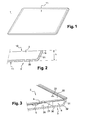
- the figure 1 illustrates according to the invention, a lighting device 1 as a whole having a substantially parallelepipedal and flat envelope structure directly intended to be associated, for example with a clean room ceiling.
- This structure is flat and homogeneous surface both on its outer surface 10 intended to be affixed against the ceiling and on its opposite outer side 11 intended to illuminate.
- the device has a height h, dimension intended to be transverse to the ceiling and separating the two opposite general faces 10 and 11, between 7 and 12 mm.
- the term "height" means the magnitude relative to the dimension intended to be normal to the receiving surface for which the device in the mounted position is intended.
- the other dimensions, length and width of the parallelepiped depend on the use and the location for which the device is intended.
- the devices may be of square section, with a side for example of 600 mm or 300 mm, or of rectangular section, for example of length 600 mm and width 200 mm.
- the ratio between the height and the width or the length of the device remains less than 0.06.
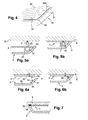
- the lighting device illustrated in more detail by the sectional view of the figure 3 comprises a plate 2 for supporting light sources and constituting the back of the device intended to be advantageously directly affixed against the ceiling, and a cover 3 closing the device and forming its facade intended to be opposite the environment of the clean room .
- the support plate 2 comprises an outer face 20 facing the outside of the device and an opposite inner face 21 facing the inside of the device, this inner face carrying a printed circuit 4 for example of the isolated metal support type (said "SMI") on which are disposed the light sources 5 formed of light emitting diodes (LEDs) and whose regulation is provided by said circuit 4.
- SMI isolated metal support type
- the circuit 4 is fixed to the inner face 21 of the plate by screwing and / or bonding, in particular using a thermal adhesive.
- the circuit 4 may also be in the form of a plurality of arrays equipped with a multitude of LEDs.
- the elements that are the support plate 2 provided with the LEDs and the cover 3 can form a one-piece assembly by the assembly method used, for example by molding, or be removable relative to each other. .
- the plate 2 is made of a rigid material chosen in particular from: aluminum, painted steel, copper, an alloy of copper and aluminum, a combination of aluminum and steel.
- Plate 2 comprises as illustrated on the figure 2 means 22 for fixing the device against the reception surface, a ceiling. These means are for example here holes that will house fastening means associated with the ceiling. These means could equally well be fastening or fixing projecting means adapted to cooperate with the reception surface.
- the cover 3 comprises a substrate 30 extending parallel to the plate 2 and side walls 31 which extend in the direction of a plane containing the plate.
- the edges 32 connecting the substrate 30 to the walls 31 are rounded, the concavity being turned towards the inside of the device.
- This concavity has a radius of curvature of at least 3 mm.
- the substrate 30 and the walls 31 may form a unitary piece or alternatively form two separate pieces which are associated with each other to provide a unitary assembly.
- the substrate 30 when the substrate 30 is independent of the walls 31, they preferably establish a frame 34, as illustrated in FIG. figure 4 provided with a flange 33 extending in the plane of the substrate 30 to provide surface continuity at the rounded-edge edge 32.
- the flange 33 may comprise a shoulder on which comes to rest the periphery 30A of the substrate 30 which is fixed by gluing or welding according to the types of materials used for the substrate and said frame.
- the walls could be made integral with the plate 2, the cover being intended to be attached against them.
- the side walls 31 have with the virtual plane of extension of the plate 2, and therefore with the ceiling against which the device will be applied, an angular orientation at an obtuse angle ⁇ , or present in a complementary manner, an acute angle with the plate 2.
- this angle ⁇ may be at least 115 °, preferably between 115 and 160 °
- the angle is adapted according to the dimensions, height, length and width, imposed on the device.
- the low height of the device (less than 12 mm) to which are added the inclination of the walls 31 and the rounded edge edges 32 ensures not to obstruct the flow of air flowing around the device, but instead participates in the stability of the aeraulic flows which advantageously follow the curves of the device.
- the external face 11 of the device corresponding to the external face of the cover 3 opposite the environment of the room is devoid of any asperities. Also it has a coefficient of roughness Ra less than or equal to 0.8 microns, preferably less than 0.4 microns.
- the support plate 2 carrying the LEDs is associated with the cover 3 via a peripheral frame 6 arranged on the internal face 35 of the cover and the height of which corresponds to the sufficient separation space between the plate 2 and the substrate 30 to accommodate the OF THE.
- the frame may be an integral part of the hood or only part of the hood, that is to say be manufactured respectively in one piece with the entire hood (substrate and side walls), or coincides with the only side walls 31 of the hood.
- the facade substrate, the side walls and the frame can be obtained by plastic injection with particular materials.
- the cover 3 is obtained in particular by a method using thermoforming, or injection molding or machining. It can be formed from transparent plastic material (s), and possibly composite material for its side walls for example. As a variant, it may be made of glass, or any other material that, however, incorporates transparent optical elements for the substrate 30 facing the LEDs.
- the substrate 30 may be manufactured independently of the side walls 31 and be secured thereto later.
- plastics material of the cap By way of examples for the plastics material of the cap, and without being limiting, mention may be made of polycarbonate (PC), polymethylmethacrylate (PMMA), high-density polyethylene (HDPE), polyethylene terephthalate (PET), polyethylene glycol (PETg).
- PC polycarbonate
- PMMA polymethylmethacrylate
- HDPE high-density polyethylene
- PET polyethylene terephthalate
- PETg polyethylene glycol
- the cover in particular its side walls 31, are for example treated or painted aluminum, painted steel, or bare steel type 300 or 400 series.
- the latter can be covered on its outer surface with a polyurethane coating which has the advantage of protecting the outer face of the cover against various cleaning, disinfection or of sterilization implemented in the clean room.
- the inner peripheral frame 6 is preferably made of plastic or composite material and is obtained by injection molding or extrusion molding. Its constituent material may be polyamide, polycarbonate (PC) or any other injectable or extrudable thermoplastic resin.
- the peripheral frame 6 is made integral with the cover 3 or at least the side walls 31.
- it is for example manufactured in one piece by molding with the side walls 31 and optionally the substrate 30.
- the peripheral frame 6 is designed to associate the support plate 2 LEDs to the cover 3 to provide a lighting device in a one-piece form. Fixing the plate 2 is for example made by screwing its periphery to the frame 6.
- the frame 6 also makes it possible to participate in fixing the device to the ceiling.
- the frame 6 has at its face 60 opposite the substrate 30 recesses 61, one of which is visible in the figures. These recesses are for example four in number being distributed at each corner of the parallelepiped forming the device. They cooperate with facing holes 22 arranged in the thickness of the plate 2, so as to receive fastening means 7 of the spring clip type which have been previously fixed to the ceiling 8.
- the fastening means 7 have been advantageously positioned by means of a template or by any suitable method such as by the use of a laser pointer.
- the peripheral frame 6 is not necessarily necessary and is not present here, the clipping means 91 being for example co-molded with the walls 31 of the hood.
- the peripheral frame 6 is integrated in the device because, made functional not only for the association of the plate 2 to the hood, but also for fixing the device to the ceiling.
- the frame has recesses, opposite which the plate 2 has orifices, clipping elements being mounted in the device through the orifices of the plate and being retained in the recesses of the frame.
- the clipping elements having been mounted prior to fixing the device to the ceiling, it remains, for fixing the device, that clip the latter on mutual cooperation elements integrated ceiling.
- Fixing this device to the ceiling 8 is as follows: the plate 2 is first fixed to the ceiling by screwing for example, then the cover 3 is attached against the plate 2 by clipping.
- sealing means are provided to ensure a seal against dust and moisture inside the device.
- the free ends or slices 36 of the side walls 31 of the cover may or may not be flush with the external face of the plate 2.
- a seal 92 such as sealant is provided on the edges 36 of the hood
- the clean room lighting device of the invention is therefore designed to avoid disruption of the flow of air flowing into the clean room.
- the device does not obstruct airflow or cause turbulence. There is no risk of contamination retention. It also benefits from a longevity of the device by the use of LEDs.
Applications Claiming Priority (1)
| Application Number | Priority Date | Filing Date | Title |
|---|---|---|---|
| FR0954648A FR2947610B1 (fr) | 2009-07-06 | 2009-07-06 | Dispositif d'eclairage pour salle propre |
Publications (2)
| Publication Number | Publication Date |
|---|---|
| EP2273184A1 true EP2273184A1 (de) | 2011-01-12 |
| EP2273184B1 EP2273184B1 (de) | 2016-08-31 |
Family
ID=41565981
Family Applications (1)
| Application Number | Title | Priority Date | Filing Date |
|---|---|---|---|
| EP10168255.7A Active EP2273184B1 (de) | 2009-07-06 | 2010-07-02 | Beleuchtungseinrichtung für reinraum |
Country Status (4)
| Country | Link |
|---|---|
| EP (1) | EP2273184B1 (de) |
| ES (1) | ES2605822T3 (de) |
| FR (1) | FR2947610B1 (de) |
| PT (1) | PT2273184T (de) |
Cited By (3)
| Publication number | Priority date | Publication date | Assignee | Title |
|---|---|---|---|---|
| CH706648A1 (de) * | 2012-06-27 | 2013-12-31 | Engeler Ag Glaswelt | Schmelzglaskörper. |
| DE102012020199A1 (de) * | 2012-10-16 | 2014-04-17 | Schilling Engineering GmbH | Beleuchtungseinheit, insbesondere Reinraumbeleuchtungseinheit |
| WO2015011179A1 (de) * | 2013-07-23 | 2015-01-29 | Zumtobel Lighting Gmbh | Led-beleuchtungsmodul |
Citations (8)
| Publication number | Priority date | Publication date | Assignee | Title |
|---|---|---|---|---|
| WO2003036159A1 (en) | 2001-10-25 | 2003-05-01 | Tir Systems Ltd. | Solid state continuous sealed clean room light fixture |
| AU2005100975A4 (en) * | 2005-11-24 | 2005-12-22 | Autumn Solar Installations Pty Limited | Surface mounted pool light |
| US20070133193A1 (en) * | 2005-12-12 | 2007-06-14 | Led Folio Corporation | Low-clearance lighting |
| US20080084693A1 (en) | 2006-10-10 | 2008-04-10 | Yanchers Corporation | Lighting system |
| US20080232093A1 (en) * | 2007-03-22 | 2008-09-25 | Led Folio Corporation | Seamless lighting assembly |
| US20080304250A1 (en) | 2007-06-06 | 2008-12-11 | Philips Lumileds Lighting Company, Llc | Thin Luminaire for General Lighting Applications |
| WO2009018433A1 (en) | 2007-07-31 | 2009-02-05 | Lsi Industries Inc. | Lighting apparatus |
| GB2452637A (en) * | 2007-09-10 | 2009-03-11 | Sanders Associates Ltd | A low profile light with anti-parallel light emitting diode circuit |
-
2009
- 2009-07-06 FR FR0954648A patent/FR2947610B1/fr not_active Expired - Fee Related
-
2010
- 2010-07-02 ES ES10168255.7T patent/ES2605822T3/es active Active
- 2010-07-02 EP EP10168255.7A patent/EP2273184B1/de active Active
- 2010-07-02 PT PT101682557T patent/PT2273184T/pt unknown
Patent Citations (8)
| Publication number | Priority date | Publication date | Assignee | Title |
|---|---|---|---|---|
| WO2003036159A1 (en) | 2001-10-25 | 2003-05-01 | Tir Systems Ltd. | Solid state continuous sealed clean room light fixture |
| AU2005100975A4 (en) * | 2005-11-24 | 2005-12-22 | Autumn Solar Installations Pty Limited | Surface mounted pool light |
| US20070133193A1 (en) * | 2005-12-12 | 2007-06-14 | Led Folio Corporation | Low-clearance lighting |
| US20080084693A1 (en) | 2006-10-10 | 2008-04-10 | Yanchers Corporation | Lighting system |
| US20080232093A1 (en) * | 2007-03-22 | 2008-09-25 | Led Folio Corporation | Seamless lighting assembly |
| US20080304250A1 (en) | 2007-06-06 | 2008-12-11 | Philips Lumileds Lighting Company, Llc | Thin Luminaire for General Lighting Applications |
| WO2009018433A1 (en) | 2007-07-31 | 2009-02-05 | Lsi Industries Inc. | Lighting apparatus |
| GB2452637A (en) * | 2007-09-10 | 2009-03-11 | Sanders Associates Ltd | A low profile light with anti-parallel light emitting diode circuit |
Cited By (3)
| Publication number | Priority date | Publication date | Assignee | Title |
|---|---|---|---|---|
| CH706648A1 (de) * | 2012-06-27 | 2013-12-31 | Engeler Ag Glaswelt | Schmelzglaskörper. |
| DE102012020199A1 (de) * | 2012-10-16 | 2014-04-17 | Schilling Engineering GmbH | Beleuchtungseinheit, insbesondere Reinraumbeleuchtungseinheit |
| WO2015011179A1 (de) * | 2013-07-23 | 2015-01-29 | Zumtobel Lighting Gmbh | Led-beleuchtungsmodul |
Also Published As
| Publication number | Publication date |
|---|---|
| ES2605822T3 (es) | 2017-03-16 |
| EP2273184B1 (de) | 2016-08-31 |
| FR2947610A1 (fr) | 2011-01-07 |
| FR2947610B1 (fr) | 2016-01-22 |
| PT2273184T (pt) | 2016-12-20 |
Similar Documents
| Publication | Publication Date | Title |
|---|---|---|
| EP3600884B1 (de) | Leuchtverglasung | |
| EP2737247B1 (de) | Leuchtende mehrfachverglasungseinheit für ein möbelstück | |
| EP2718530B1 (de) | Beleuchtungseinheit aus eine isolierverglasung und leuchtdioden | |
| EP3044500B1 (de) | Lichtmodul mit einer organischen lichtemittierenden diode | |
| EP2273184B1 (de) | Beleuchtungseinrichtung für reinraum | |
| EP3049715A1 (de) | Fahrzeugscheinwerfer mit einem dekorativen zubehör | |
| WO2012168659A1 (fr) | Cloison eclairante en verre | |
| BE1025411B1 (fr) | Tête de luminaire modulaire | |
| EP2875288B1 (de) | Beleuchtungswand | |
| FR2978526A1 (fr) | Vitrage multiple lumineux de batiment | |
| FR3052145A1 (fr) | Dispositif d'eclairage pour un espace interieur d'un vehicule | |
| EP2718512B1 (de) | Leuchtende glasstrennwand | |
| FR3081782A1 (fr) | Ensemble de signalisation pour vantail, porte et vehicule de transport correspondants | |
| BE1025233B1 (fr) | Disposif de fixation de luminaire sans outil | |
| EP3230651A1 (de) | System zur visuellen signalisierung | |
| FR3088869A1 (fr) | Dispositif de pré-positionnement et de maintien d’un élément sur un boitier | |
| FR2944531A1 (fr) | Plot d'eclairage. | |
| FR3138503A3 (fr) | Dispositif universel d’éclairage pour le relampage de luminaires | |
| WO2013150220A1 (fr) | Dispositif d'éclairage à diodes électroluminescentes | |
| FR2843182A1 (fr) | Appareil d'eclairage encastrable | |
| FR3060713A3 (fr) | Element optique pour dispositif de signalisation lumineuse et dispositif de signalisation lumineuse dote dudit element optique | |
| FR3078766A1 (fr) | Structure a diffusion de lumiere uniforme | |
| FR2976339A1 (fr) | Ensemble eclairant a base d'un vitrage isolant et de diodes electroluminescentes | |
| CH708836A1 (fr) | Dispositif d'éclairage pour environnement dit propre. | |
| FR3040467A1 (fr) | Structure lumineuse comprenant un eclairage indirect |
Legal Events
| Date | Code | Title | Description |
|---|---|---|---|
| PUAI | Public reference made under article 153(3) epc to a published international application that has entered the european phase |
Free format text: ORIGINAL CODE: 0009012 |
|
| AK | Designated contracting states |
Kind code of ref document: A1 Designated state(s): AL AT BE BG CH CY CZ DE DK EE ES FI FR GB GR HR HU IE IS IT LI LT LU LV MC MK MT NL NO PL PT RO SE SI SK SM TR |
|
| AX | Request for extension of the european patent |
Extension state: BA ME RS |
|
| 17P | Request for examination filed |
Effective date: 20101213 |
|
| RIC1 | Information provided on ipc code assigned before grant |
Ipc: F21V 17/16 20060101ALN20141127BHEP Ipc: F21Y 101/02 20060101ALN20141127BHEP Ipc: F21W 131/402 20060101ALN20141127BHEP Ipc: F21S 8/04 20060101AFI20141127BHEP |
|
| GRAP | Despatch of communication of intention to grant a patent |
Free format text: ORIGINAL CODE: EPIDOSNIGR1 |
|
| INTG | Intention to grant announced |
Effective date: 20150122 |
|
| RIC1 | Information provided on ipc code assigned before grant |
Ipc: F21S 8/04 20060101AFI20160331BHEP Ipc: F21V 17/16 20060101ALN20160331BHEP Ipc: F21K 99/00 20160101ALN20160331BHEP Ipc: F21W 131/402 20060101ALN20160331BHEP |
|
| GRAP | Despatch of communication of intention to grant a patent |
Free format text: ORIGINAL CODE: EPIDOSNIGR1 |
|
| GRAS | Grant fee paid |
Free format text: ORIGINAL CODE: EPIDOSNIGR3 |
|
| INTG | Intention to grant announced |
Effective date: 20160506 |
|
| GRAA | (expected) grant |
Free format text: ORIGINAL CODE: 0009210 |
|
| AK | Designated contracting states |
Kind code of ref document: B1 Designated state(s): AL AT BE BG CH CY CZ DE DK EE ES FI FR GB GR HR HU IE IS IT LI LT LU LV MC MK MT NL NO PL PT RO SE SI SK SM TR |
|
| REG | Reference to a national code |
Ref country code: GB Ref legal event code: FG4D Free format text: NOT ENGLISH Ref country code: CH Ref legal event code: EP |
|
| REG | Reference to a national code |
Ref country code: IE Ref legal event code: FG4D Free format text: LANGUAGE OF EP DOCUMENT: FRENCH |
|
| REG | Reference to a national code |
Ref country code: DE Ref legal event code: R096 Ref document number: 602010035939 Country of ref document: DE |
|
| REG | Reference to a national code |
Ref country code: AT Ref legal event code: REF Ref document number: 825310 Country of ref document: AT Kind code of ref document: T Effective date: 20161015 |
|
| RAP2 | Party data changed (patent owner data changed or rights of a patent transferred) |
Owner name: LUCISBIO |
|
| REG | Reference to a national code |
Ref country code: DE Ref legal event code: R081 Ref document number: 602010035939 Country of ref document: DE Owner name: LUCISBIO, FR Free format text: FORMER OWNER: LUCISBIO, LARCAY, FR |
|
| REG | Reference to a national code |
Ref country code: NL Ref legal event code: FP |
|
| REG | Reference to a national code |
Ref country code: CH Ref legal event code: NV Representative=s name: MICHELI AND CIE SA, CH |
|
| REG | Reference to a national code |
Ref country code: PT Ref legal event code: SC4A Ref document number: 2273184 Country of ref document: PT Date of ref document: 20161220 Kind code of ref document: T Free format text: AVAILABILITY OF NATIONAL TRANSLATION Effective date: 20161129 |
|
| REG | Reference to a national code |
Ref country code: LT Ref legal event code: MG4D |
|
| PG25 | Lapsed in a contracting state [announced via postgrant information from national office to epo] |
Ref country code: LT Free format text: LAPSE BECAUSE OF FAILURE TO SUBMIT A TRANSLATION OF THE DESCRIPTION OR TO PAY THE FEE WITHIN THE PRESCRIBED TIME-LIMIT Effective date: 20160831 Ref country code: FI Free format text: LAPSE BECAUSE OF FAILURE TO SUBMIT A TRANSLATION OF THE DESCRIPTION OR TO PAY THE FEE WITHIN THE PRESCRIBED TIME-LIMIT Effective date: 20160831 Ref country code: NO Free format text: LAPSE BECAUSE OF FAILURE TO SUBMIT A TRANSLATION OF THE DESCRIPTION OR TO PAY THE FEE WITHIN THE PRESCRIBED TIME-LIMIT Effective date: 20161130 Ref country code: HR Free format text: LAPSE BECAUSE OF FAILURE TO SUBMIT A TRANSLATION OF THE DESCRIPTION OR TO PAY THE FEE WITHIN THE PRESCRIBED TIME-LIMIT Effective date: 20160831 |
|
| PG25 | Lapsed in a contracting state [announced via postgrant information from national office to epo] |
Ref country code: SE Free format text: LAPSE BECAUSE OF FAILURE TO SUBMIT A TRANSLATION OF THE DESCRIPTION OR TO PAY THE FEE WITHIN THE PRESCRIBED TIME-LIMIT Effective date: 20160831 Ref country code: GR Free format text: LAPSE BECAUSE OF FAILURE TO SUBMIT A TRANSLATION OF THE DESCRIPTION OR TO PAY THE FEE WITHIN THE PRESCRIBED TIME-LIMIT Effective date: 20161201 Ref country code: LV Free format text: LAPSE BECAUSE OF FAILURE TO SUBMIT A TRANSLATION OF THE DESCRIPTION OR TO PAY THE FEE WITHIN THE PRESCRIBED TIME-LIMIT Effective date: 20160831 |
|
| REG | Reference to a national code |
Ref country code: ES Ref legal event code: FG2A Ref document number: 2605822 Country of ref document: ES Kind code of ref document: T3 Effective date: 20170316 |
|
| PG25 | Lapsed in a contracting state [announced via postgrant information from national office to epo] |
Ref country code: EE Free format text: LAPSE BECAUSE OF FAILURE TO SUBMIT A TRANSLATION OF THE DESCRIPTION OR TO PAY THE FEE WITHIN THE PRESCRIBED TIME-LIMIT Effective date: 20160831 Ref country code: RO Free format text: LAPSE BECAUSE OF FAILURE TO SUBMIT A TRANSLATION OF THE DESCRIPTION OR TO PAY THE FEE WITHIN THE PRESCRIBED TIME-LIMIT Effective date: 20160831 |
|
| PG25 | Lapsed in a contracting state [announced via postgrant information from national office to epo] |
Ref country code: DK Free format text: LAPSE BECAUSE OF FAILURE TO SUBMIT A TRANSLATION OF THE DESCRIPTION OR TO PAY THE FEE WITHIN THE PRESCRIBED TIME-LIMIT Effective date: 20160831 Ref country code: BG Free format text: LAPSE BECAUSE OF FAILURE TO SUBMIT A TRANSLATION OF THE DESCRIPTION OR TO PAY THE FEE WITHIN THE PRESCRIBED TIME-LIMIT Effective date: 20161130 Ref country code: PL Free format text: LAPSE BECAUSE OF FAILURE TO SUBMIT A TRANSLATION OF THE DESCRIPTION OR TO PAY THE FEE WITHIN THE PRESCRIBED TIME-LIMIT Effective date: 20160831 Ref country code: SK Free format text: LAPSE BECAUSE OF FAILURE TO SUBMIT A TRANSLATION OF THE DESCRIPTION OR TO PAY THE FEE WITHIN THE PRESCRIBED TIME-LIMIT Effective date: 20160831 Ref country code: SM Free format text: LAPSE BECAUSE OF FAILURE TO SUBMIT A TRANSLATION OF THE DESCRIPTION OR TO PAY THE FEE WITHIN THE PRESCRIBED TIME-LIMIT Effective date: 20160831 Ref country code: CZ Free format text: LAPSE BECAUSE OF FAILURE TO SUBMIT A TRANSLATION OF THE DESCRIPTION OR TO PAY THE FEE WITHIN THE PRESCRIBED TIME-LIMIT Effective date: 20160831 |
|
| REG | Reference to a national code |
Ref country code: DE Ref legal event code: R097 Ref document number: 602010035939 Country of ref document: DE |
|
| PLBE | No opposition filed within time limit |
Free format text: ORIGINAL CODE: 0009261 |
|
| STAA | Information on the status of an ep patent application or granted ep patent |
Free format text: STATUS: NO OPPOSITION FILED WITHIN TIME LIMIT |
|
| REG | Reference to a national code |
Ref country code: FR Ref legal event code: PLFP Year of fee payment: 8 |
|
| 26N | No opposition filed |
Effective date: 20170601 |
|
| PG25 | Lapsed in a contracting state [announced via postgrant information from national office to epo] |
Ref country code: SI Free format text: LAPSE BECAUSE OF FAILURE TO SUBMIT A TRANSLATION OF THE DESCRIPTION OR TO PAY THE FEE WITHIN THE PRESCRIBED TIME-LIMIT Effective date: 20160831 |
|
| PG25 | Lapsed in a contracting state [announced via postgrant information from national office to epo] |
Ref country code: LU Free format text: LAPSE BECAUSE OF NON-PAYMENT OF DUE FEES Effective date: 20170702 |
|
| REG | Reference to a national code |
Ref country code: FR Ref legal event code: PLFP Year of fee payment: 9 |
|
| PG25 | Lapsed in a contracting state [announced via postgrant information from national office to epo] |
Ref country code: MT Free format text: LAPSE BECAUSE OF FAILURE TO SUBMIT A TRANSLATION OF THE DESCRIPTION OR TO PAY THE FEE WITHIN THE PRESCRIBED TIME-LIMIT Effective date: 20160831 |
|
| PG25 | Lapsed in a contracting state [announced via postgrant information from national office to epo] |
Ref country code: AL Free format text: LAPSE BECAUSE OF FAILURE TO SUBMIT A TRANSLATION OF THE DESCRIPTION OR TO PAY THE FEE WITHIN THE PRESCRIBED TIME-LIMIT Effective date: 20160831 |
|
| REG | Reference to a national code |
Ref country code: AT Ref legal event code: UEP Ref document number: 825310 Country of ref document: AT Kind code of ref document: T Effective date: 20160831 |
|
| PG25 | Lapsed in a contracting state [announced via postgrant information from national office to epo] |
Ref country code: MC Free format text: LAPSE BECAUSE OF FAILURE TO SUBMIT A TRANSLATION OF THE DESCRIPTION OR TO PAY THE FEE WITHIN THE PRESCRIBED TIME-LIMIT Effective date: 20160831 Ref country code: HU Free format text: LAPSE BECAUSE OF FAILURE TO SUBMIT A TRANSLATION OF THE DESCRIPTION OR TO PAY THE FEE WITHIN THE PRESCRIBED TIME-LIMIT; INVALID AB INITIO Effective date: 20100702 |
|
| PG25 | Lapsed in a contracting state [announced via postgrant information from national office to epo] |
Ref country code: CY Free format text: LAPSE BECAUSE OF NON-PAYMENT OF DUE FEES Effective date: 20160831 |
|
| PG25 | Lapsed in a contracting state [announced via postgrant information from national office to epo] |
Ref country code: MK Free format text: LAPSE BECAUSE OF FAILURE TO SUBMIT A TRANSLATION OF THE DESCRIPTION OR TO PAY THE FEE WITHIN THE PRESCRIBED TIME-LIMIT Effective date: 20160831 |
|
| PG25 | Lapsed in a contracting state [announced via postgrant information from national office to epo] |
Ref country code: TR Free format text: LAPSE BECAUSE OF FAILURE TO SUBMIT A TRANSLATION OF THE DESCRIPTION OR TO PAY THE FEE WITHIN THE PRESCRIBED TIME-LIMIT Effective date: 20160831 |
|
| PG25 | Lapsed in a contracting state [announced via postgrant information from national office to epo] |
Ref country code: IS Free format text: LAPSE BECAUSE OF FAILURE TO SUBMIT A TRANSLATION OF THE DESCRIPTION OR TO PAY THE FEE WITHIN THE PRESCRIBED TIME-LIMIT Effective date: 20161231 |
|
| PGFP | Annual fee paid to national office [announced via postgrant information from national office to epo] |
Ref country code: PT Payment date: 20230629 Year of fee payment: 14 |
|
| PGFP | Annual fee paid to national office [announced via postgrant information from national office to epo] |
Ref country code: NL Payment date: 20230724 Year of fee payment: 14 |
|
| PGFP | Annual fee paid to national office [announced via postgrant information from national office to epo] |
Ref country code: IT Payment date: 20230724 Year of fee payment: 14 Ref country code: IE Payment date: 20230724 Year of fee payment: 14 Ref country code: GB Payment date: 20230728 Year of fee payment: 14 Ref country code: ES Payment date: 20230808 Year of fee payment: 14 Ref country code: CH Payment date: 20230801 Year of fee payment: 14 Ref country code: AT Payment date: 20230724 Year of fee payment: 14 |
|
| PGFP | Annual fee paid to national office [announced via postgrant information from national office to epo] |
Ref country code: FR Payment date: 20230725 Year of fee payment: 14 Ref country code: DE Payment date: 20230724 Year of fee payment: 14 Ref country code: BE Payment date: 20230725 Year of fee payment: 14 |