EP2273103A2 - Rotorblatt für eine Windenergieanlage und Verfahren zu dessen Herstellung - Google Patents
Rotorblatt für eine Windenergieanlage und Verfahren zu dessen Herstellung Download PDFInfo
- Publication number
- EP2273103A2 EP2273103A2 EP10005434A EP10005434A EP2273103A2 EP 2273103 A2 EP2273103 A2 EP 2273103A2 EP 10005434 A EP10005434 A EP 10005434A EP 10005434 A EP10005434 A EP 10005434A EP 2273103 A2 EP2273103 A2 EP 2273103A2
- Authority
- EP
- European Patent Office
- Prior art keywords
- rotor blade
- web
- profile
- belt
- connection profile
- Prior art date
- Legal status (The legal status is an assumption and is not a legal conclusion. Google has not performed a legal analysis and makes no representation as to the accuracy of the status listed.)
- Withdrawn
Links
- 238000004519 manufacturing process Methods 0.000 title claims abstract description 15
- 238000000034 method Methods 0.000 title claims description 17
- 239000000463 material Substances 0.000 claims abstract description 10
- 229920002430 Fibre-reinforced plastic Polymers 0.000 claims abstract description 8
- 239000011151 fibre-reinforced plastic Substances 0.000 claims abstract description 8
- 239000000853 adhesive Substances 0.000 claims description 24
- 230000001070 adhesive effect Effects 0.000 claims description 24
- 238000003780 insertion Methods 0.000 claims description 5
- 230000037431 insertion Effects 0.000 claims description 5
- 238000004026 adhesive bonding Methods 0.000 claims 1
- 150000001875 compounds Chemical class 0.000 claims 1
- 230000003014 reinforcing effect Effects 0.000 description 6
- 239000003822 epoxy resin Substances 0.000 description 2
- 239000011521 glass Substances 0.000 description 2
- 229920000647 polyepoxide Polymers 0.000 description 2
- 230000009467 reduction Effects 0.000 description 2
- 238000010008 shearing Methods 0.000 description 2
- 125000006850 spacer group Chemical group 0.000 description 2
- 238000005452 bending Methods 0.000 description 1
- 239000000969 carrier Substances 0.000 description 1
- 230000008859 change Effects 0.000 description 1
- 238000012937 correction Methods 0.000 description 1
- 238000006073 displacement reaction Methods 0.000 description 1
- 230000000694 effects Effects 0.000 description 1
- 238000001125 extrusion Methods 0.000 description 1
- 230000002349 favourable effect Effects 0.000 description 1
- 239000002657 fibrous material Substances 0.000 description 1
- 239000003292 glue Substances 0.000 description 1
- 238000011090 industrial biotechnology method and process Methods 0.000 description 1
- 238000009434 installation Methods 0.000 description 1
- 238000010030 laminating Methods 0.000 description 1
- 238000003475 lamination Methods 0.000 description 1
- 230000003287 optical effect Effects 0.000 description 1
- 229920001225 polyester resin Polymers 0.000 description 1
- 239000004645 polyester resin Substances 0.000 description 1
- 238000009417 prefabrication Methods 0.000 description 1
- 230000008569 process Effects 0.000 description 1
- 230000002787 reinforcement Effects 0.000 description 1
- 230000007704 transition Effects 0.000 description 1
- 238000009827 uniform distribution Methods 0.000 description 1
- 238000009736 wetting Methods 0.000 description 1
- 230000037303 wrinkles Effects 0.000 description 1
Images


Classifications
-
- F—MECHANICAL ENGINEERING; LIGHTING; HEATING; WEAPONS; BLASTING
- F03—MACHINES OR ENGINES FOR LIQUIDS; WIND, SPRING, OR WEIGHT MOTORS; PRODUCING MECHANICAL POWER OR A REACTIVE PROPULSIVE THRUST, NOT OTHERWISE PROVIDED FOR
- F03D—WIND MOTORS
- F03D1/00—Wind motors with rotation axis substantially parallel to the air flow entering the rotor
- F03D1/06—Rotors
- F03D1/065—Rotors characterised by their construction elements
- F03D1/0675—Rotors characterised by their construction elements of the blades
-
- B—PERFORMING OPERATIONS; TRANSPORTING
- B29—WORKING OF PLASTICS; WORKING OF SUBSTANCES IN A PLASTIC STATE IN GENERAL
- B29C—SHAPING OR JOINING OF PLASTICS; SHAPING OF MATERIAL IN A PLASTIC STATE, NOT OTHERWISE PROVIDED FOR; AFTER-TREATMENT OF THE SHAPED PRODUCTS, e.g. REPAIRING
- B29C65/00—Joining or sealing of preformed parts, e.g. welding of plastics materials; Apparatus therefor
- B29C65/48—Joining or sealing of preformed parts, e.g. welding of plastics materials; Apparatus therefor using adhesives, i.e. using supplementary joining material; solvent bonding
- B29C65/50—Joining or sealing of preformed parts, e.g. welding of plastics materials; Apparatus therefor using adhesives, i.e. using supplementary joining material; solvent bonding using adhesive tape, e.g. thermoplastic tape; using threads or the like
- B29C65/5064—Joining or sealing of preformed parts, e.g. welding of plastics materials; Apparatus therefor using adhesives, i.e. using supplementary joining material; solvent bonding using adhesive tape, e.g. thermoplastic tape; using threads or the like of particular form, e.g. being C-shaped, T-shaped
- B29C65/5071—Joining or sealing of preformed parts, e.g. welding of plastics materials; Apparatus therefor using adhesives, i.e. using supplementary joining material; solvent bonding using adhesive tape, e.g. thermoplastic tape; using threads or the like of particular form, e.g. being C-shaped, T-shaped and being composed by one single element
-
- B—PERFORMING OPERATIONS; TRANSPORTING
- B29—WORKING OF PLASTICS; WORKING OF SUBSTANCES IN A PLASTIC STATE IN GENERAL
- B29C—SHAPING OR JOINING OF PLASTICS; SHAPING OF MATERIAL IN A PLASTIC STATE, NOT OTHERWISE PROVIDED FOR; AFTER-TREATMENT OF THE SHAPED PRODUCTS, e.g. REPAIRING
- B29C65/00—Joining or sealing of preformed parts, e.g. welding of plastics materials; Apparatus therefor
- B29C65/48—Joining or sealing of preformed parts, e.g. welding of plastics materials; Apparatus therefor using adhesives, i.e. using supplementary joining material; solvent bonding
- B29C65/50—Joining or sealing of preformed parts, e.g. welding of plastics materials; Apparatus therefor using adhesives, i.e. using supplementary joining material; solvent bonding using adhesive tape, e.g. thermoplastic tape; using threads or the like
- B29C65/5064—Joining or sealing of preformed parts, e.g. welding of plastics materials; Apparatus therefor using adhesives, i.e. using supplementary joining material; solvent bonding using adhesive tape, e.g. thermoplastic tape; using threads or the like of particular form, e.g. being C-shaped, T-shaped
- B29C65/5085—Joining or sealing of preformed parts, e.g. welding of plastics materials; Apparatus therefor using adhesives, i.e. using supplementary joining material; solvent bonding using adhesive tape, e.g. thermoplastic tape; using threads or the like of particular form, e.g. being C-shaped, T-shaped and comprising grooves, e.g. being E-shaped, H-shaped
-
- B—PERFORMING OPERATIONS; TRANSPORTING
- B29—WORKING OF PLASTICS; WORKING OF SUBSTANCES IN A PLASTIC STATE IN GENERAL
- B29C—SHAPING OR JOINING OF PLASTICS; SHAPING OF MATERIAL IN A PLASTIC STATE, NOT OTHERWISE PROVIDED FOR; AFTER-TREATMENT OF THE SHAPED PRODUCTS, e.g. REPAIRING
- B29C66/00—General aspects of processes or apparatus for joining preformed parts
- B29C66/01—General aspects dealing with the joint area or with the area to be joined
- B29C66/05—Particular design of joint configurations
- B29C66/10—Particular design of joint configurations particular design of the joint cross-sections
- B29C66/11—Joint cross-sections comprising a single joint-segment, i.e. one of the parts to be joined comprising a single joint-segment in the joint cross-section
- B29C66/112—Single lapped joints
-
- B—PERFORMING OPERATIONS; TRANSPORTING
- B29—WORKING OF PLASTICS; WORKING OF SUBSTANCES IN A PLASTIC STATE IN GENERAL
- B29C—SHAPING OR JOINING OF PLASTICS; SHAPING OF MATERIAL IN A PLASTIC STATE, NOT OTHERWISE PROVIDED FOR; AFTER-TREATMENT OF THE SHAPED PRODUCTS, e.g. REPAIRING
- B29C66/00—General aspects of processes or apparatus for joining preformed parts
- B29C66/01—General aspects dealing with the joint area or with the area to be joined
- B29C66/05—Particular design of joint configurations
- B29C66/10—Particular design of joint configurations particular design of the joint cross-sections
- B29C66/11—Joint cross-sections comprising a single joint-segment, i.e. one of the parts to be joined comprising a single joint-segment in the joint cross-section
- B29C66/114—Single butt joints
-
- B—PERFORMING OPERATIONS; TRANSPORTING
- B29—WORKING OF PLASTICS; WORKING OF SUBSTANCES IN A PLASTIC STATE IN GENERAL
- B29C—SHAPING OR JOINING OF PLASTICS; SHAPING OF MATERIAL IN A PLASTIC STATE, NOT OTHERWISE PROVIDED FOR; AFTER-TREATMENT OF THE SHAPED PRODUCTS, e.g. REPAIRING
- B29C66/00—General aspects of processes or apparatus for joining preformed parts
- B29C66/40—General aspects of joining substantially flat articles, e.g. plates, sheets or web-like materials; Making flat seams in tubular or hollow articles; Joining single elements to substantially flat surfaces
- B29C66/41—Joining substantially flat articles ; Making flat seams in tubular or hollow articles
- B29C66/43—Joining a relatively small portion of the surface of said articles
- B29C66/432—Joining a relatively small portion of the surface of said articles for making tubular articles or closed loops, e.g. by joining several sheets ; for making hollow articles or hollow preforms
- B29C66/4326—Joining a relatively small portion of the surface of said articles for making tubular articles or closed loops, e.g. by joining several sheets ; for making hollow articles or hollow preforms for making hollow articles or hollow-preforms, e.g. half-shells
-
- B—PERFORMING OPERATIONS; TRANSPORTING
- B29—WORKING OF PLASTICS; WORKING OF SUBSTANCES IN A PLASTIC STATE IN GENERAL
- B29C—SHAPING OR JOINING OF PLASTICS; SHAPING OF MATERIAL IN A PLASTIC STATE, NOT OTHERWISE PROVIDED FOR; AFTER-TREATMENT OF THE SHAPED PRODUCTS, e.g. REPAIRING
- B29C66/00—General aspects of processes or apparatus for joining preformed parts
- B29C66/40—General aspects of joining substantially flat articles, e.g. plates, sheets or web-like materials; Making flat seams in tubular or hollow articles; Joining single elements to substantially flat surfaces
- B29C66/41—Joining substantially flat articles ; Making flat seams in tubular or hollow articles
- B29C66/43—Joining a relatively small portion of the surface of said articles
- B29C66/434—Joining substantially flat articles for forming corner connections, fork connections or cross connections
- B29C66/4344—Joining substantially flat articles for forming fork connections, e.g. for making Y-shaped pieces
- B29C66/43441—Joining substantially flat articles for forming fork connections, e.g. for making Y-shaped pieces with two right angles, e.g. for making T-shaped pieces, H-shaped pieces
-
- B—PERFORMING OPERATIONS; TRANSPORTING
- B29—WORKING OF PLASTICS; WORKING OF SUBSTANCES IN A PLASTIC STATE IN GENERAL
- B29C—SHAPING OR JOINING OF PLASTICS; SHAPING OF MATERIAL IN A PLASTIC STATE, NOT OTHERWISE PROVIDED FOR; AFTER-TREATMENT OF THE SHAPED PRODUCTS, e.g. REPAIRING
- B29C66/00—General aspects of processes or apparatus for joining preformed parts
- B29C66/70—General aspects of processes or apparatus for joining preformed parts characterised by the composition, physical properties or the structure of the material of the parts to be joined; Joining with non-plastics material
- B29C66/72—General aspects of processes or apparatus for joining preformed parts characterised by the composition, physical properties or the structure of the material of the parts to be joined; Joining with non-plastics material characterised by the structure of the material of the parts to be joined
- B29C66/721—Fibre-reinforced materials
-
- B—PERFORMING OPERATIONS; TRANSPORTING
- B29—WORKING OF PLASTICS; WORKING OF SUBSTANCES IN A PLASTIC STATE IN GENERAL
- B29C—SHAPING OR JOINING OF PLASTICS; SHAPING OF MATERIAL IN A PLASTIC STATE, NOT OTHERWISE PROVIDED FOR; AFTER-TREATMENT OF THE SHAPED PRODUCTS, e.g. REPAIRING
- B29C66/00—General aspects of processes or apparatus for joining preformed parts
- B29C66/50—General aspects of joining tubular articles; General aspects of joining long products, i.e. bars or profiled elements; General aspects of joining single elements to tubular articles, hollow articles or bars; General aspects of joining several hollow-preforms to form hollow or tubular articles
- B29C66/51—Joining tubular articles, profiled elements or bars; Joining single elements to tubular articles, hollow articles or bars; Joining several hollow-preforms to form hollow or tubular articles
- B29C66/53—Joining single elements to tubular articles, hollow articles or bars
- B29C66/532—Joining single elements to the wall of tubular articles, hollow articles or bars
-
- B—PERFORMING OPERATIONS; TRANSPORTING
- B29—WORKING OF PLASTICS; WORKING OF SUBSTANCES IN A PLASTIC STATE IN GENERAL
- B29C—SHAPING OR JOINING OF PLASTICS; SHAPING OF MATERIAL IN A PLASTIC STATE, NOT OTHERWISE PROVIDED FOR; AFTER-TREATMENT OF THE SHAPED PRODUCTS, e.g. REPAIRING
- B29C66/00—General aspects of processes or apparatus for joining preformed parts
- B29C66/50—General aspects of joining tubular articles; General aspects of joining long products, i.e. bars or profiled elements; General aspects of joining single elements to tubular articles, hollow articles or bars; General aspects of joining several hollow-preforms to form hollow or tubular articles
- B29C66/51—Joining tubular articles, profiled elements or bars; Joining single elements to tubular articles, hollow articles or bars; Joining several hollow-preforms to form hollow or tubular articles
- B29C66/54—Joining several hollow-preforms, e.g. half-shells, to form hollow articles, e.g. for making balls, containers; Joining several hollow-preforms, e.g. half-cylinders, to form tubular articles
-
- B—PERFORMING OPERATIONS; TRANSPORTING
- B29—WORKING OF PLASTICS; WORKING OF SUBSTANCES IN A PLASTIC STATE IN GENERAL
- B29C—SHAPING OR JOINING OF PLASTICS; SHAPING OF MATERIAL IN A PLASTIC STATE, NOT OTHERWISE PROVIDED FOR; AFTER-TREATMENT OF THE SHAPED PRODUCTS, e.g. REPAIRING
- B29C66/00—General aspects of processes or apparatus for joining preformed parts
- B29C66/50—General aspects of joining tubular articles; General aspects of joining long products, i.e. bars or profiled elements; General aspects of joining single elements to tubular articles, hollow articles or bars; General aspects of joining several hollow-preforms to form hollow or tubular articles
- B29C66/61—Joining from or joining on the inside
-
- B—PERFORMING OPERATIONS; TRANSPORTING
- B29—WORKING OF PLASTICS; WORKING OF SUBSTANCES IN A PLASTIC STATE IN GENERAL
- B29C—SHAPING OR JOINING OF PLASTICS; SHAPING OF MATERIAL IN A PLASTIC STATE, NOT OTHERWISE PROVIDED FOR; AFTER-TREATMENT OF THE SHAPED PRODUCTS, e.g. REPAIRING
- B29C66/00—General aspects of processes or apparatus for joining preformed parts
- B29C66/50—General aspects of joining tubular articles; General aspects of joining long products, i.e. bars or profiled elements; General aspects of joining single elements to tubular articles, hollow articles or bars; General aspects of joining several hollow-preforms to form hollow or tubular articles
- B29C66/63—Internally supporting the article during joining
- B29C66/636—Internally supporting the article during joining using a support which remains in the joined object
-
- B—PERFORMING OPERATIONS; TRANSPORTING
- B29—WORKING OF PLASTICS; WORKING OF SUBSTANCES IN A PLASTIC STATE IN GENERAL
- B29C—SHAPING OR JOINING OF PLASTICS; SHAPING OF MATERIAL IN A PLASTIC STATE, NOT OTHERWISE PROVIDED FOR; AFTER-TREATMENT OF THE SHAPED PRODUCTS, e.g. REPAIRING
- B29C66/00—General aspects of processes or apparatus for joining preformed parts
- B29C66/70—General aspects of processes or apparatus for joining preformed parts characterised by the composition, physical properties or the structure of the material of the parts to be joined; Joining with non-plastics material
- B29C66/71—General aspects of processes or apparatus for joining preformed parts characterised by the composition, physical properties or the structure of the material of the parts to be joined; Joining with non-plastics material characterised by the composition of the plastics material of the parts to be joined
-
- B—PERFORMING OPERATIONS; TRANSPORTING
- B29—WORKING OF PLASTICS; WORKING OF SUBSTANCES IN A PLASTIC STATE IN GENERAL
- B29C—SHAPING OR JOINING OF PLASTICS; SHAPING OF MATERIAL IN A PLASTIC STATE, NOT OTHERWISE PROVIDED FOR; AFTER-TREATMENT OF THE SHAPED PRODUCTS, e.g. REPAIRING
- B29C66/00—General aspects of processes or apparatus for joining preformed parts
- B29C66/70—General aspects of processes or apparatus for joining preformed parts characterised by the composition, physical properties or the structure of the material of the parts to be joined; Joining with non-plastics material
- B29C66/72—General aspects of processes or apparatus for joining preformed parts characterised by the composition, physical properties or the structure of the material of the parts to be joined; Joining with non-plastics material characterised by the structure of the material of the parts to be joined
- B29C66/721—Fibre-reinforced materials
- B29C66/7212—Fibre-reinforced materials characterised by the composition of the fibres
-
- B—PERFORMING OPERATIONS; TRANSPORTING
- B29—WORKING OF PLASTICS; WORKING OF SUBSTANCES IN A PLASTIC STATE IN GENERAL
- B29L—INDEXING SCHEME ASSOCIATED WITH SUBCLASS B29C, RELATING TO PARTICULAR ARTICLES
- B29L2031/00—Other particular articles
- B29L2031/08—Blades for rotors, stators, fans, turbines or the like, e.g. screw propellers
- B29L2031/082—Blades, e.g. for helicopters
- B29L2031/085—Wind turbine blades
-
- Y—GENERAL TAGGING OF NEW TECHNOLOGICAL DEVELOPMENTS; GENERAL TAGGING OF CROSS-SECTIONAL TECHNOLOGIES SPANNING OVER SEVERAL SECTIONS OF THE IPC; TECHNICAL SUBJECTS COVERED BY FORMER USPC CROSS-REFERENCE ART COLLECTIONS [XRACs] AND DIGESTS
- Y02—TECHNOLOGIES OR APPLICATIONS FOR MITIGATION OR ADAPTATION AGAINST CLIMATE CHANGE
- Y02E—REDUCTION OF GREENHOUSE GAS [GHG] EMISSIONS, RELATED TO ENERGY GENERATION, TRANSMISSION OR DISTRIBUTION
- Y02E10/00—Energy generation through renewable energy sources
- Y02E10/70—Wind energy
- Y02E10/72—Wind turbines with rotation axis in wind direction
-
- Y—GENERAL TAGGING OF NEW TECHNOLOGICAL DEVELOPMENTS; GENERAL TAGGING OF CROSS-SECTIONAL TECHNOLOGIES SPANNING OVER SEVERAL SECTIONS OF THE IPC; TECHNICAL SUBJECTS COVERED BY FORMER USPC CROSS-REFERENCE ART COLLECTIONS [XRACs] AND DIGESTS
- Y02—TECHNOLOGIES OR APPLICATIONS FOR MITIGATION OR ADAPTATION AGAINST CLIMATE CHANGE
- Y02P—CLIMATE CHANGE MITIGATION TECHNOLOGIES IN THE PRODUCTION OR PROCESSING OF GOODS
- Y02P70/00—Climate change mitigation technologies in the production process for final industrial or consumer products
- Y02P70/50—Manufacturing or production processes characterised by the final manufactured product
-
- Y—GENERAL TAGGING OF NEW TECHNOLOGICAL DEVELOPMENTS; GENERAL TAGGING OF CROSS-SECTIONAL TECHNOLOGIES SPANNING OVER SEVERAL SECTIONS OF THE IPC; TECHNICAL SUBJECTS COVERED BY FORMER USPC CROSS-REFERENCE ART COLLECTIONS [XRACs] AND DIGESTS
- Y10—TECHNICAL SUBJECTS COVERED BY FORMER USPC
- Y10T—TECHNICAL SUBJECTS COVERED BY FORMER US CLASSIFICATION
- Y10T29/00—Metal working
- Y10T29/49—Method of mechanical manufacture
- Y10T29/49316—Impeller making
- Y10T29/49336—Blade making
- Y10T29/49339—Hollow blade
Definitions
- the invention relates to a rotor blade for a wind energy plant, which comprises at least one pair of opposing belts which extend in the longitudinal direction of the rotor blade and absorb forces acting on the rotor blade, and at least one web which has two end faces, which respectively face one of the two belts. and has two side surfaces, extending between the two straps in the longitudinal direction of the rotor blade and fixedly connected to the two straps, and a method for producing such rotor blades.
- Known rotor blades of this type consist of two half-shells, which are connected to each other. Each half shell has one of the straps, usually in the area of the largest profile height.
- the straps can be made integral with the half-shells and give the rotor blade, inter alia, its bending stiffness.
- the quality of the connection of the at least one web with the straps is made.
- the webs of known rotor blades at their ends facing the straps angled mounting portions which are glued to the straps.
- Cross-sectionally C-shaped webs are known, in which the angled sections form flanges extending to one side of the web, and cross-sectionally double-T-shaped webs, the fastening sections of which extend from the web to both sides.
- the webs can lock and make an exact arrangement of the two shells impossible. In these cases, the web must be cut in the longitudinal direction and its upper half be brought by suitable means in a lower position. The separating cut can then be laminated on both sides laterally with a defined layer structure. If the intended inside clear distance between the two half-shells is exceeded, the adhesive gaps for the bonding of webs and half-shell insides may become too large, which may necessitate laminating layers on the adhesive surfaces of the webs in order to reduce the gap in question.
- a manufacturing mold for manufacturing a rotor blade for a wind turbine wherein the finished rotor blade has at least in a region of its longitudinal extent, between a rotor blade root and a rotor blade tip, an aerodynamic cross-sectional profile having a profile leading edge and a profile trailing edge has, which are interconnected via a suction side and a pressure side of the cross-sectional profile.
- WO 2006/039953 A1 is a rotor blade for a wind turbine is known in which along the contact points of an upper shell and longitudinal edges of the rotor blade for reinforcement angle structures of mats are glued with a fiber material.
- a shear web extends between a pressure side and a suction side of a rotor blade.
- the shearing land has a resilient and / or expandable spacer to fit the shearing land.
- the two straps can each be connected to or made integral with a half shell, which forms an outer contour of the rotor blade.
- the straps give the rotor blade its flexural rigidity.
- the rotor blade may have a plurality of pairs of opposing straps, for example two main straps arranged in the area of the largest profile height and two end edge straps running in the region of the end edge of the profile.
- a single web or a plurality of webs may be arranged.
- two main straps may be connected by two spaced webs.
- the two webs can be arranged parallel or not parallel to each other.
- Additional end edge straps may e.g. be connected by a single bridge.
- the at least one web may be rectangular or trapezoidal in cross section, for example. However, it is also possible a cross section with curved and / or stepped edges, in which the thickness of the web can vary.
- Cross-section now and in the following always means a section perpendicular to a longitudinal axis of the rotor blade.
- the two side surfaces of the at least one web can each be arranged in a plane which extends from one of the two straps to the opposite belt.
- connection profile establishes the connection between one of the straps and the at least one web. It has a receptacle into which the at least one web is inserted.
- the receptacle is such that it facilitates the correct positioning of the web.
- the recording may predetermine the position of the at least one web in two or three directions, for example forming a boundary to the left, to the bottom and to the right.
- the bonding of the first surface of the connection profile with one of the belts and the bonding of the second surface of the connection profile with a first side surface of the at least one web is preferably a large-area bonding with a contact surface which is larger than one of the end faces of the at least one web. This favors a stable bond.
- the manufacture and assembly of the rotor blade can be substantially simplified.
- the webs may have a simpler geometry, as known from the prior art webs with angled mounting portions.
- they can be made from a flat laminate.
- the connecting surfaces between the webs and straps can be dimensioned more freely by appropriate selection of the cross section of the connecting profile.
- the connection profile can be easily manufactured using industrial processes, in particular in the extrusion process.
- the angle between the first side surface and the end surface of the at least one web may be a right angle or deviate from a right angle, in particular to take account of an inclination of the web relative to the belt.
- the first side surface and the end surface may include an angle in the range of 75 ° to 105 °.
- the end face may preferably be arranged parallel to the adjacent belt.
- the same angle may be formed between the first surface of the connection profile glued to the belt and the second surface of the connection profile glued to the first side surface of the web.
- the first side surface of the web and the second surface of the connection profile are arranged in parallel, so that a uniform adhesive joint results.
- the receptacle is a groove in the connection profile.
- the groove may for example have a rectangular cross-section.
- the lateral surfaces of the groove can also be arranged at an angle to each other or have a different height.
- the use of a groove as a receptacle allows accurate positioning of the at least one ridge in the groove.
- a third surface of the connection profile is adhesively bonded to a second side surface of the at least one web opposite the first side surface. So there is a two-sided and therefore particularly strong bonding of the web.
- connection profile is in two parts in cross section and consists of two adjacently arranged profiles. The inclusion of the connection profile is then formed between the adjacent profiles.
- the two adjacent profiles can be glued at a predetermined distance with the belt.
- the profiles may, for example, have an angular, triangular or box-shaped cross section.
- connection profile in cross section is integral with a U-shaped portion having a base and two legs which form the receptacle.
- a one-piece cross-section connection profile can be particularly easily glued to the belt, the dimensional accuracy of the recording is ensured by the correspondingly accurate prefabrication of the connection profile.
- the second surface of the connection profile can be formed by an inside of a leg, the third surface of the connection profile from the inside of the opposite leg of the U-profile.
- the legs of the U-profile can be aligned parallel to each other.
- the connecting areas between the legs and the base of the U-profile may be square or more or less rounded.
- the transition regions of the side surfaces to the end face of the at least one web can then also be correspondingly rounded.
- the first surface of the connection profile is formed from the outside of the base of the U-shaped portion.
- connection profile in cross-section at least one broadening, which adjoins laterally to the base of the U-shaped portion. It can only be provided a widening, which adjoins one side of the base of the U-shaped portion, while the leg of the U-profile remote from this widening forms the lateral end of the connecting profile.
- two widenings may also be provided on both sides of the base of the U-shaped section, so that both legs of the U-profile are at a distance from the lateral edges of the widened base of the connection profile.
- the at least one broadening allows a firmer bond between the connection profile and the belt, because the surface to be bonded is increased.
- the ends of the legs remote from the base are inclined in the cross section of the connecting profile to the receptacle.
- the inclined surfaces facilitate the insertion of the at least one web in the formed between the two legs receiving the connection profile.
- an end face of the at least one web is adhesively bonded to the connecting profile. This allows a further increase in the strength of the adhesive bond.
- the end face of the at least one web can in particular be adhesively bonded to an inner side of a base of the U-profile.
- connection profile consists of a fiber-reinforced plastic material.
- This material has a high strength and is especially for the bonding with the belt and the at least one web, which may also consist of fiber-reinforced plastic material, particularly favorable.
- profiles of fiber reinforced plastic material can be easily manufactured using industrial techniques.
- a plurality of connecting profiles are lined up in the longitudinal direction of the rotor blade.
- a single connection profile can be used, which extends over the entire length of the rotor blade or of the at least one web.
- the individual sections can be connected to each other via suitable connecting means.
- the cross section of the connection profile changes in the longitudinal direction of the rotor blade. This solution comes into consideration both when using a single connection profile and when using a segmented connection profile. If several connection profiles are strung together, they can each have a constant cross section, which makes their production particularly simple. Alternatively, the cross-section of the connection profile may change continuously or in steps over the entire length. Particularly useful is a reduction in the height of the connection profile to the blade tips, according to the reduction in the height of the at least one web.
- the at least one web is also connected to the belt opposite the first belt via a connecting profile, wherein the connection is designed according to one of the above-explained claims.
- the at least one web is connected to both the lower and the upper shell of the rotor blade by means of a connection profile.
- This method considerably simplifies the manufacture of the rotor blade, in particular because the insertion of the web into the connecting profile previously glued to the belt is simple and enables accurate positioning of the at least one web.
- a positioning aid is provided for bonding the first surface of the connection profile to the first belt and / or the second surface of the connection profile to the first side surface of the at least one web used.
- the positioning aid can be, for example, an optical marking, for example using a laser projection. It may also be a mechanical support which predetermines the arrangement of the connection profile or of the at least one web with respect to the respective belt or the respective half shell of the rotor blade or a mold used for the production of this half shell.
- the receptacle of the connection profile is filled with adhesive up to a predetermined fill level prior to insertion of the at least one web.
- the adhesive can also be applied to the contact surfaces of the at least one web to be bonded. Scheduled filling of the receptacle, however, makes it easier to apply the correct amount of adhesive.
- the adhesive assembly may be secured with a position assurance to prevent dripping or leakage of the adhesive from the receptacle. This position assurance, for example, a strip-shaped material can then be removed immediately before the insertion of the web into the receptacle.
- a connecting profile with a receptacle for the at least one web is also used to connect the at least one web to the second belt, wherein this connecting profile is bonded to the second belt and a side surface of the at least one web.
- the connection profiles which are glued to the two straps optionally be glued in the same operation with the at least one web.
- the elements of the rotor blade according to one of claims 1 to 11 are configured.
- the explained in this regard features and advantages can then be achieved with the appropriately designed method.
- FIG. 1 shows a section of a cross section through a rotor blade according to the invention.
- the upper half-shell 10 is indicated, which forms the aerodynamic shell of the rotor blade.
- the lower half-shell 12 of the rotor blade located at the bottom of the figure, the lower half-shell 12 of the rotor blade.
- a belt 14 of the rotor blade is connected to the first half shell 10
- a belt 16 of the rotor blade is fixedly connected to the second half shell 12.
- the two straps 14, 16 each consist of a variety of glass shelves z. B. impregnated with a polyester or epoxy resin and glued to a laminate.
- the straps 14, 16 are arranged in the region of the largest profile height of the rotor blade and extend in its longitudinal direction.
- the two straps 14, 16 are opposite each other.
- the two straps 14, 16 are connected by two webs 18, 20 fixed to each other, which extend between the two straps 14, 16 in the longitudinal direction of the rotor blade.
- Each of the webs 18, 20 has two end faces 22 and two side surfaces 24.
- connection profiles 26, 28, 30 and 32 there are four connection profiles 26, 28, 30 and 32.
- the connection profiles 26 and 28 connect the web 18 and 20 with the belt 14.
- the connection profiles 30 and 32 connect the webs 18 and 20 with the belt 16.
- Each of the connection profiles 26, 28, 30, 32 is in one piece in cross section.
- the cross section of each connection profile 26, 28, 30, 32 has a U-shaped section with a base 34 and two legs 36, as shown by way of example on the connection profile 30.
- On the base 34 of the U-profile widenings 38, 40 adjoin on both sides, whose outer ends determine the width of the connecting profile 30 and the width of a first surface 42 of the connecting profile 30, which is glued to the belt 16.
- Between the first surface 42 of the connection profile 30 and the belt 16 adhesive 44 is arranged, in particular based on an epoxy resin.
- the widening 40 has approximately twice the width of the widening 38.
- the widening 38 extends from the base 34 of the U-shaped section towards a lateral edge of the belt 16, while the other widening 40 of the connection profile 30 extends from the base 34 of the connection profile 30 towards the center of the belt 16 ,
- the base 34 of the U-shaped portion of the connecting profile 30 and the two spacers 38, 40 together form a base plate of the connecting profile 30, the lower surface 42 is flat.
- the base 34 and the two legs 36 of the U-shaped portion of the connection profile 30 form a receptacle for a lower end of the web 18.
- the inside of a leg 36 forms a second surface of the connection profile, which is glued to a side surface 24 of the web 18.
- the inside of the opposite leg 36 is glued to the web 18, namely with its opposite side surface 24.
- Between the inner sides of the legs 36 and the side surfaces 24 is also adhesive as between the inside of the base 34 and the end face 22 of the web 18th
- connection profile 30 and its connection to the belt 16 and the web 18 apply analogously to the other connection profiles 26, 28 and 32nd
- FIG. 2 shows possible embodiments of connection profiles with different cross-sections.
- Figure a) shows a connection profile 46 with a U-shaped cross-section. It has a base 48 and two legs 50 which are interconnected. The two legs 50 extend in a parallel orientation and at right angles to the base 48. The ends of the two legs 50 remote from the base 48 each have a surface 52 which slopes towards the receptacle formed between the two legs 50 and the base 48 is.
- connection profile 54 shown in cross section. It also has a U-shaped section with a base 56 and two legs 58. In addition, there is a widening 60, which adjoins the side of the base 56 and causes an enlargement of the first surface 62, which is intended for connection to a belt.
- a further connecting profile 64 is shown, which also has a U-shaped portion with a base 66 and two legs 68, as already explained with respect to part a) of the figure.
- the base 66 is followed by extensions 70, 72 on both sides.
- the widening 70 has a greater width than the widening 72.
- the widenings 70, 72 together with the base form a flat base plate of the connecting profile 64.
- connection profile 74 has a total of approximately triangular, one-piece cross-section.
- a receptacle 76 is formed, to the two sides of each triangular sections 78, 80 of the connecting profile 74 are arranged.
- the two triangular sections 78, 80 are connected by a base 82 and are both arranged on an imaginary base plate 82.
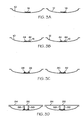
- FIG. 3 shows two juxtaposed half-shells 10, 12 of a rotor blade, which can be located in the figures used for the production of the half-shells 10, 12 forms, which are not shown in detail.
- the two half shells 10, 12 are arranged side by side, with the sides of the half shells 10, 12 facing the inside of the rotor blade facing upwards.
- the half-shell 10 has a belt 14 extending approximately in its center in the longitudinal direction of the rotor blade, and the half-shell 12 has a belt 16 extending approximately in its center also in the longitudinal direction of the rotor blade.
- the adhesive 44 is arranged strip-shaped near the two lateral edges of the belt 14, 16 in the intended contact area to the connection profiles 26, 28, 30, 32.
- connection profiles 26, 28, 30 and 32 are applied to the previously applied adhesive 44.
- the connection profiles 26, 28, 30, 32 are each arranged so that the receptacles formed between two legs for the webs face the inside of the rotor blade.
- Part d) of the figure shows the exact positioning of the connection profiles 26, 28, 30, 32 based on two positioning aids.
- the positioning aids are mechanical supports 84, each having a cross member 86 and two attached, downwardly facing support 88.
- Each of the carriers 88 engages in a receptacle of a connection profile 26, 28, 30, 32 and thus determines the position of the respective connection profile 26, 28, 30, 32 firmly.
- the cross members 86 of the brackets 84 are each supported in a defined position on the edges of the half-shells 10, 12 or at the edges of the associated forms. As a result, an exact positioning of the connection profiles 26, 28, 30, 32 with respect to the half-shells 10, 12 is ensured.
- brackets 84 are removed and - as shown in part e) of the figure - the recordings of the connection profiles 26, 28, 30, 32 filled with adhesive 90, up to a defined level.
- the webs 18, 20, if necessary With the help of a suitable web setting device, in the recordings of the connection profiles 30, 32 used. They dive into the adhesive 90 so that it is distributed between the boundary surfaces of the receptacles and the adjacent end and side surfaces of the webs 18, 20.
- the half-shell 10 is folded onto the half-shell 12, wherein the edges of the half-shells 10, 12 are glued together.
- the webs 18, 20 in the connected to the belt 14 connecting profiles 26, 28, more precisely in the recordings formed by these, inserted and glued therein.
- the two straps 14, 16 are fixedly connected to the webs 18, 20.
Abstract
Description
- Die Erfindung betrifft ein Rotorblatt für eine Windenergieanlage, das mindestens ein Paar einander gegenüberliegender Gurte, die sich in Längsrichtung des Rotorblatts erstrecken und auf das Rotorblatt einwirkende Kräfte aufnehmen, und mindestens einen Steg, der zwei Stirnflächen, die jeweils einem der beiden Gurte zugewandt sind, und zwei Seitenflächen besitzt, sich zwischen den beiden Gurten in Längsrichtung des Rotorblatts erstreckt und fest mit den beiden Gurten verbunden ist, aufweist, sowie ein Verfahren zur Herstellung derartiger Rotorblätter.
- Bekannte Rotorblätter dieser Bauart bestehen aus zwei Halbschalen, die miteinander verbunden sind. Jede Halbschale weist, in der Regel im Bereich der größten Profilhöhe, einen der Gurte auf. Die Gurte können integral mit den Halbschalen gefertigt sein und verleihen dem Rotorblatt unter anderem seine Biegeschlagsteifigkeit. Von großer Bedeutung für die Festigkeit des Rotorblatts ist die Qualität der Verbindung des mindestens einen Stegs mit den Gurten. In der Regel wird eine großflächige Verklebung vorgenommen. Hierzu weisen die Stege bekannter Rotorblätter an ihren den Gurten zugewandten Enden abgewinkelte Befestigungsabschnitte auf, die mit den Gurten verklebt werden. Bekannt sind im Querschnitt C-förmige Stege, bei denen die abgewinkelten Abschnitte sich zu einer Seite des Stegs erstreckende Flansche bilden, und im Querschnitt doppel-T-förmige Stege, deren Befestigungsabschnitte sich ausgehend von dem Steg zu beiden Seiten erstrecken.
- Mit derartigen Befestigungsabschnitten an den Stegen kann eine ausreichend feste Verbindung zu den Gurten erreicht werden. Der Einbau der Stege ist jedoch problematisch. In der Regel wird zunächst der gesamte Steg mit dem Gurt der ersten Halbschale verklebt. Um den Steg möglichst zeichnungsgerecht zu positionieren, kann eine sogenannte Stegsetzvorrichtung verwendet werden. Wegen der nicht immer maßhaltigen Innenkontur der Halbschale bzw. der an dem Befestigungsabschnitt des Stegs angrenzenden Kontaktfläche des Gurtes kann es jedoch leicht zu Positionsabweichungen des Steges kommen. Die Ungenauigkeiten in der Innenkontur der Halbschalen ergeben sich durch die Fertigung der Halbschalen in offenen Formen. Insbesondere können beim Laminieren der Glasgelege Wellen oder Falten entstehen. Anschließend wird die zweite Halbschale aufgesetzt und mit der ersten Halbschale und dem Steg verklebt. Diese Verklebung wird als Blindverklebung bezeichnet, da nach dem Aufsetzen der zweiten Halbschale große Bereiche nicht mehr zugänglich sind und die Qualität daher nicht oder nur schwer kontrolliert werden kann.
- Wegen der genannten Toleranzen der Innenkonturen der Halbschalen und der Ungenauigkeiten bei der Positionierung der Stege können aufwendige Nacharbeiten erforderlich sein: Wird die vorgesehene lichte Innenweite zwischen den Halbschalen unterschritten, können die Stege sperren und eine exakte Anordnung der beiden Halbschalen unmöglich machen. In diesen Fällen muss der Steg in Längsrichtung eingeschnitten und seine obere Hälfte mit geeigneten Mitteln in eine tiefere Position gebracht werden. Der Trennschnitt kann dann seitlich mit festgelegtem Lagenaufbau beidseitig überlaminiert werden. Wird die vorgesehene lichte Innenweite zwischen den beiden Halbschalen überschritten, können die Klebespalte für die Verklebung von Stegen und Halbschaleninnenseiten zu groß werden, was ein Auflaminieren von Lagen auf den Klebeflächen der Stege erforderlich machen kann, um das betreffende Spaltmaß zu verringern.
- In der nachveröffentlichten Druckschrift
DE 10 2008 038 620 A1 ist eine Fertigungsform zur Fertigung eines Rotorblatts für eine Windenergieanlage beschrieben, wobei das fertige Rotorblatt wenigstens in einem Bereich seiner Längserstreckung, zwischen einer Rotorblattwurzel und einer Rotorblattspitze, ein aerodynamisches Querschnittsprofil aufweist, das eine Profilvorderkante und eine Profilhinterkante aufweist, die über eine Saugseite und eine Druckseite des Querschnittsprofils miteinander verbunden sind. - Aus der Druckschrift
WO 2008/104171 A2 ist eine Verstärkungsstruktur für ein Rotorblatt einer Windenergieanlage bekannt. Zwei Verstärkungsteile sind mit zwei Rotorblattteilen verbunden, wobei eines der Verstärkungsteile Einstellmittel aufweist, so dass die beiden Verstärkungsteile während der Montage des Rotorblatts gegeneinander verschiebbar sind. Die Einstellmittel üben eine Kraft aus, die die Verstärkungsteile von einander zu entfernen sucht. - Aus der Druckschrift
WO 2006/039953 A1 ist ein Rotorblatt für eine Windenergieanlage bekannt, bei dem längs der Berührungsstellen einer Oberschale und Längsspanten des Rotorblatts zur Verstärkung Winkelstrukturen aus Matten mit einem Fasermaterial aufgeklebt sind. - Aus der Druckschrift
WO 2008/071195 A2 ist ein verstärktes aerodynamisches Profil bekannt. Im Inneren des Profils sind unterschiedliche Verstärkungsstrukturen angeordnet. - Aus der Druckschrift
DE 10 2008 037 386 A1 sind Windkraftanlagenholme mit gegliederten Scherstegen bekannt. Ein Schersteg erstreckt sich zwischen einer Druckseite und einer Saugseite eines Rotorflügels. Der Schersteg weist einen nachgiebigen und/oder erweiterbaren Abstandhalter auf, um den Schersteg einzupassen. - Davon ausgehend ist es die Aufgabe der Erfindung, ein Rotorblatt und ein Verfahren zu dessen Herstellung anzugeben, dass eine bessere Verbindung zwischen den Stegen und den Gurten des Rotorblatts sowie eine einfachere und maßhaltigere Montage des Rotorblatts ermöglicht.
- Diese Aufgabe wird gelöst durch das Rotorblatt mit den Merkmalen des Anspruchs 1. Vorteilhafte Ausgestaltungen sind in den sich anschließenden Unteransprüchen angegeben.
- Das erfindungsgemäße Rotorblatt für eine Windenergieanlage hat:
- mindestens ein Paar einander gegenüberliegender Gurte, die sich in Längsrichtung des Rotorblatts erstrecken und auf das Rotorblatt einwirkende Kräfte aufnehmen, und
- mindestens einen Steg, der zwei Stirnflächen, die jeweils einem der beiden Gurte zugewandt sind, und zwei Seitenflächen aufweist, sich zwischen den beiden Gurten in Längsrichtung des Rotorblatts erstreckt und fest mit den beiden Gurten verbunden ist, wobei
- mindestens ein in Längsrichtung des Rotorblatts verlaufendes, aus einem faserverstärkten Kunststoffmaterial bestehendes, im Querschnitt ein- oder mehrteiliges Verbindungsprofil mit einer Aufnahme vorhanden ist, in die der mindestens eine Steg eingesetzt ist,
- eine erste Fläche des Verbindungsprofils mit einem der Gurte verklebt ist und
- eine zweite Fläche des Verbindungsprofils mit einer ersten Seitenfläche des mindestens einen Stegs verklebt ist.
- Die beiden Gurte können mit jeweils einer Halbschale, die eine Außenkontur des Rotorblatts bildet, verbunden oder integral mit dieser gefertigt sein. Die Gurte verleihen dem Rotorblatt unter anderem seine Biegeschlagsteifigkeit. Das Rotorblatt kann mehrere Paare einander gegenüberliegender Gurte aufweisen, beispielsweise zwei Hauptgurte, die im Bereich der größten Profilhöhe angeordnet sind, und zwei Endkantengurte, die im Bereich der Endkante des Profils verlaufen.
- Zwischen jedem Paar einander gegenüberliegender Gurte kann ein einziger Steg oder können mehrere Stege angeordnet sein. Beispielsweise können zwei Hauptgurte durch zwei in einem Abstand voneinander angeordnete Stege verbunden sein. Die beiden Stege können parallel oder nicht parallel zueinander angeordnet sein. Zusätzlich vorhandene Endkantengurte können z.B. durch einen einzigen Steg verbunden sein.
- Der mindestens eine Steg kann im Querschnitt beispielsweise rechteckig oder trapezförmig sein. Möglich ist jedoch auch ein Querschnitt mit gekrümmten und/oder gestuften Kanten, bei dem die Dicke des Stegs variieren kann. Querschnitt bedeutet jetzt und im Folgenden stets einen Schnitt senkrecht zu einer Längsachse des Rotorblatts. Die beiden Seitenflächen des mindestens einen Stegs können jeweils in einer Ebene angeordnet sein, die sich von einem der beiden Gurte zu dem gegenüberliegenden Gurt erstreckt.
- Das Verbindungsprofil stellt die Verbindung zwischen einem der Gurte und dem mindestens einen Steg her. Es weist eine Aufnahme auf, in die der mindestens eine Steg eingesetzt ist. Die Aufnahme ist insbesondere so beschaffen, dass sie die korrekte Positionierung des Stegs vereinfacht. Insbesondere kann die Aufnahme die Position des mindestens einen Stegs in zwei oder drei Richtungen vorgeben, beispielsweise nach links, nach unten und nach rechts eine Begrenzung bilden.
- Die Verklebung der ersten Fläche des Verbindungsprofils mit einem der Gurte und die Verklebung der zweiten Fläche des Verbindungsprofils mit einer ersten Seitenfläche des mindestens einen Stegs ist bevorzugt eine großflächige Verklebung mit einer Kontaktfläche, die größer ist als eine der Stirnflächen des mindestens einen Stegs. Dadurch wird eine stabile Verklebung begünstigt.
- Durch die Erfindung kann die Herstellung und Montage des Rotorblatts wesentlich vereinfacht werden. Insbesondere können die Stege eine einfachere Geometrie aufweisen, als aus dem Stand der Technik bekannte Stege mit abgewinkelten Befestigungsabschnitten. Sie können insbesondere aus einem ebenen Laminat hergestellt werden. Die Verbindungsflächen zwischen den Stegen und Gurten können freier dimensioniert werden durch entsprechende Wahl des Querschnitts des Verbindungsprofils. Das Verbindungsprofil kann einfach unter Verwendung industrieller Verfahren, insbesondere im Extrudierverfahren, hergestellt werden.
- Durch die erfindungsgemäß vorgesehene Verklebung des Verbindungsprofils mit einer Seitenfläche des mindestens einen Stegs wirken sich Abweichungen in der lichten Innenweite zwischen den Gurten nicht mehr gravierend auf die Qualität und Geometrie der Verklebung zwischen Steg und Gurt aus, weil die häufig unvermeidbaren Ungenauigkeiten nicht in Richtung des Spaltmaßes zwischen den zu verklebenden Teilen auftreten, wie bei einer konventionellen Verklebung eines dem Gurt zugewandten Befestigungsflansches mit dem Gurt. Stattdessen können bei der Erfindung derartige Toleranzen einfach durch eine bezüglich der Klebefuge seitliche Verschiebung der zu verklebenden Teile ausgeglichen werden. Insbesondere kann der Steg etwas weniger tief in die Aufnahme eines Verbindungsprofils eingesetzt werden, wenn die lichte Innenweite größer ist als ihr Sollwert, oder etwas tiefer, wenn die lichte Innenweite kleiner ist als ihr Sollwert. Diese Korrekturen haben bei einer ausreichenden seitlichen Erstreckung der Klebefuge, die durch entsprechende Wahl der Tiefe der Aufnahme vorgebbar ist, keinen nennenswerten Einfluss auf die Festigkeit der Klebverbindung.
- Der Winkel zwischen der ersten Seitenfläche und der Stirnfläche des mindestens einen Stegs kann ein rechter Winkel sein oder von einem rechten Winkel abweichen, insbesondere um einer Neigung des Stegs gegenüber dem Gurt Rechnung zu tragen. Beispielsweise können die erste Seitenfläche und die Stirnfläche einen Winkel im Bereich von 75° bis 105° einschließen. Dabei kann die Stirnfläche bevorzugt parallel zu dem benachbarten Gurt angeordnet sein. Bevorzugt kann zwischen der ersten Fläche des Verbindungsprofils, die mit dem Gurt verklebt ist, und der zweiten Fläche des Verbindungsprofils, die mit der ersten Seitenfläche des Stegs verklebt ist, der gleiche Winkel ausgebildet sein. In diesem Fall sind die erste Seitenfläche des Stegs und die zweite Fläche des Verbindungsprofils parallel angeordnet, so dass sich eine gleichmäßige Klebefuge ergibt.
- Gemäß einer Ausgestaltung ist die Aufnahme eine Nut in dem Verbindungsprofil. Die Nut kann beispielsweise einen rechteckigen Querschnitt aufweisen. Die seitlichen Flächen der Nut können jedoch auch unter einem Winkel zueinander angeordnet sein oder eine unterschiedliche Höhe aufweisen. Die Verwendung einer Nut als Aufnahme ermöglicht eine genaue Positionierung des mindestens einen Stegs in der Nut.
- Gemäß einer Ausgestaltung ist eine dritte Fläche des Verbindungsprofils mit einer zweiten, der ersten Seitenfläche gegenüberliegenden Seitenfläche des mindestens einen Stegs verklebt. Es erfolgt also eine beidseitige und daher besonders feste Verklebung des Stegs.
- In einer Ausgestaltung ist das Verbindungsprofil im Querschnitt zweiteilig und besteht aus zwei benachbart angeordneten Profilen. Die Aufnahme des Verbindungsprofils ist dann zwischen den benachbarten Profilen ausgebildet. Die beiden benachbarten Profile können in einem vorgegebenen Abstand mit dem Gurt verklebt werden. Die Profile können beispielsweise einen winkelförmigen, dreieckigen oder kastenförmigen Querschnitt aufweisen.
- Gemäß einer Ausgestaltung ist das Verbindungsprofil im Querschnitt einteilig mit einem U-förmigen Abschnitt, der eine Basis und zwei Schenkel aufweist, die die Aufnahme bilden. Ein im Querschnitt einteiliges Verbindungsprofil kann besonders einfach mit dem Gurt verklebt werden, wobei die Maßhaltigkeit der Aufnahme durch die entsprechend genaue Vorfertigung des Verbindungsprofils sichergestellt ist. Die zweite Fläche des Verbindungsprofils kann von einer Innenseite eines Schenkels, die dritte Fläche des Verbindungsprofils von der Innenseite des gegenüberliegenden Schenkels des U-Profils gebildet werden. Die Schenkel des U-Profils können parallel zueinander ausgerichtet sein. Die Verbindungsbereiche zwischen den Schenkeln und der Basis des U-Profils können eckig oder mehr oder weniger stark abgerundet ausgeführt sein. Die Übergangsbereiche der Seitenflächen zur Stirnfläche des mindestens einen Stegs können dann ebenfalls entsprechend abgerundet sein.
- In einer Ausgestaltung ist die erste Fläche des Verbindungsprofils von der Außenseite der Basis des U-förmigen Abschnitts gebildet.
- In einer Ausgestaltung weist das Verbindungsprofil im Querschnitt mindestens eine Verbreiterung auf, die sich seitlich an die Basis des U-förmigen Abschnitts anschließt. Es kann lediglich eine Verbreiterung vorgesehen sein, die sich an eine Seite der Basis des U-förmigen Abschnitts anschließt, während der von dieser Verbreiterung entfernte Schenkel des U-Profils den seitlichen Abschluss des Verbindungsprofils bildet. Es können jedoch auch zwei Verbreiterungen an beiden Seiten der Basis des U-förmigen Abschnitts vorgesehen sein, sodass sich beide Schenkel des U-Profils in einem Abstand von den seitlichen Kanten der verbreiterten Grundfläche des Verbindungsprofils befinden. Die mindestens eine Verbreiterung ermöglicht eine festere Klebverbindung zwischen dem Verbindungsprofil und dem Gurt, weil die zu verklebende Fläche vergrößert wird.
- Gemäß einer Ausgestaltung sind die von der Basis entfernten Enden der Schenkel im Querschnitt des Verbindungsprofils zu der Aufnahme hin geneigt. Die geneigten Flächen erleichtern das Einführen des mindestens einen Stegs in die zwischen den beiden Schenkeln gebildete Aufnahme des Verbindungsprofils.
- Gemäß einer Ausgestaltung ist eine Stirnfläche des mindestens einen Stegs mit dem Verbindungsprofil verklebt. Dies ermöglicht eine weitere Steigerung der Festigkeit der Klebverbindung. Im Falle eines Verbindungsprofils mit im Querschnitt U-förmigem Abschnitt kann die Stirnfläche des mindestens einen Stegs insbesondere mit einer Innenseite einer Basis des U-Profils verklebt sein.
- In einer Ausgestaltung besteht das Verbindungsprofil aus einem faserverstärkten Kunststoffmaterial. Dieses Material weist eine hohe Festigkeit auf und ist insbesondere für die Verklebung mit dem Gurt und dem mindestens einen Steg, die ebenfalls aus faserverstärktem Kunststoffmaterial bestehen können, besonders günstig. Profile aus faserverstärktem Kunststoffmaterial können zudem leicht unter Verwendung industrieller Techniken hergestellt werden.
- Gemäß einer Ausgestaltung sind in Längsrichtung des Rotorblatts mehrere Verbindungsprofile aneinandergereiht. Grundsätzlich kann ein einziges Verbindungsprofil verwendet werden, das sich über die gesamte Länge des Rotorblatts bzw. des mindestens einen Stegs erstreckt. Einfacher zu transportieren und zu lagern ist jedoch ein aus mehreren Teilstücken bestehendes Verbindungsprofil. Beispielsweise können einige Meter lange Verbindungsprofile, beispielsweise mit einer Länge von fünf Metern, verwendet werden. Die einzelnen Teilstücke können über geeignete Verbindungsmittel miteinander verbunden werden.
- In einer Ausgestaltung ändert sich der Querschnitt des Verbindungsprofils in Längsrichtung des Rotorblatts. Diese Lösung kommt sowohl bei Verwendung eines einzigen Verbindungsprofils als auch bei Verwendung eines segmentierten Verbindungsprofils in Betracht. Sofern mehrere Verbindungsprofile aneinandergereiht werden, können diese einen jeweils konstanten Querschnitt aufweisen, was deren Fertigung besonders einfach macht. Alternativ kann sich der Querschnitt des Verbindungsprofils über die gesamte Länge kontinuierlich oder gestuft ändern. Insbesondere sinnvoll ist eine Verringerung der Höhe des Verbindungsprofils zu den Blattspitzen hin, entsprechend der Verringerung der Höhe des mindestens einen Stegs.
- In einer Ausgestaltung ist der mindestens eine Steg auch mit dem dem ersten Gurt gegenüberliegenden Gurt über ein Verbindungsprofil verbunden, wobei die Verbindung entsprechend einem der vorstehend erläuterten Ansprüche ausgestaltet ist. In diesem Fall ist der mindestens eine Steg sowohl mit der Unter- als auch mit der Oberschale des Rotorblatts mit Hilfe eines Verbindungsprofils verbunden.
- Die oben genannte Aufgabe wird ebenfalls gelöst durch das Verfahren zur Herstellung eines Rotorblatts einer Windenergieanlage mit den Merkmalen des Anspruchs 12. Vorteilhafte Ausgestaltungen des Verfahrens sind in den sich anschließenden Unteransprüchen angegeben.
- Das erfindungsgemäße Verfahren weist die folgenden Schritte auf:
- Bereitstellen einer ersten Halbschale, die einen ersten Gurt aufweist, der sich in Längsrichtung des Rotorblatts erstreckt und auf das Rotorblatt einwirkende Kräfte aufnimmt,
- Verkleben einer ersten Fläche eines im Querschnitt ein- oder mehrteiligen Verbindungsprofils mit dem ersten Gurt, wobei das Verbindungsprofil in Längsrichtung des Gurtes angeordnet ist und aus einem faserverstärkten Kunststoffmaterial besteht,
- Einsetzen mindestens eines Stegs, der eine Stirnfläche, die im fertigen Rotorblatt dem ersten Gurt zugewandt ist, und zwei Seitenflächen aufweist, in eine Aufnahme des Verbindungsprofils,
- Verkleben einer zweiten Fläche des Verbindungsprofils mit einer ersten Seitenfläche des mindestens einen Stegs,
- Verbinden einer zweiten Halbschale, die einen im fertigen Rotorblatt dem ersten Gurt gegenüberliegenden zweiten Gurt aufweist, mit der ersten Halbschale und dem mindestens einen Steg.
- Dieses Verfahren vereinfacht die Herstellung des Rotorblatts erheblich, insbesondere weil das Einsetzen des Steges in das zuvor mit dem Gurt verklebte Verbindungsprofil einfach ist und eine genaue Positionierung des mindestens einen Stegs ermöglicht.
- Hinsichtlich der bereits bei der Erläuterung des erfindungsgemäßen Rotorblatts diskutierten Merkmale wird auf diese Erläuterungen verwiesen, die sich analog auf die korrespondierenden Verfahrensmerkmale beziehen.
- Gemäß einer Ausgestaltung des Verfahrens wird für das Verkleben der ersten Fläche des Verbindungsprofils mit dem ersten Gurt und/oder der zweiten Fläche des Verbindungsprofils mit der ersten Seitenfläche des mindestens einen Stegs eine Positionierhilfe verwendet. Die Positionierhilfe kann beispielsweise eine optische Markierung, etwa unter Verwendung einer Laserprojektion, sein. Es kann sich auch um eine mechanische Halterung handeln, die die Anordnung des Verbindungsprofils bzw. des mindestens einen Stegs gegenüber dem jeweiligen Gurt bzw. der jeweiligen Halbschale des Rotorblatts oder einer für die Fertigung dieser Halbschale verwendeten Form vorgibt.
- Gemäß einer Ausgestaltung des Verfahrens wird die Aufnahme des Verbindungsprofils vor dem Einsetzen des mindestens einen Stegs bis zu einem vorgegebenen Füllstand mit Klebstoff gefüllt. Grundsätzlich kann der Klebstoff auch auf die zu verklebenden Kontaktflächen des mindestens einen Stegs aufgetragen werden. Ein planmäßiges Befüllen der Aufnahme erleichtert jedoch die richtige Menge an Klebstoff aufzutragen. Durch das Einsetzen des mindestens einen Stegs in die mindestens teilweise mit Klebstoff befüllte Aufnahme wird zudem eine gleichmäßige Verteilung des Klebstoffs und gute Benetzung aller zu verklebenden Kontaktflächen des mindestens einen Stegs und des Verbindungsprofils erreicht. Wahlweise kann nach dem Füllen der Aufnahme mit dem Klebstoff die Klebstoffanordnung mit einer Lagesicherung zur Verhinderung des Abtropfens oder Auslaufens des Klebstoffs aus der Aufnahme gesichert werden. Diese Lagesicherung, beispielsweise ein streifenförmiges Material, kann dann unmittelbar vor dem Einsetzen des Stegs in die Aufnahme entfernt werden.
- Gemäß einer Ausgestaltung wird zur Verbindung des mindestens einen Stegs mit dem zweiten Gurt ebenfalls ein Verbindungsprofil mit einer Aufnahme für den mindestens einen Steg verwendet, wobei dieses Verbindungsprofil mit dem zweiten Gurt und einer Seitenfläche des mindestens einen Stegs verklebt wird. Dabei können die Verbindungsprofile, die mit den beiden Gurten verklebt sind, wahlweise im gleichen Arbeitsgang mit dem mindestens einen Steg verklebt werden.
- Gemäß einer weiteren Ausgestaltung des Verfahrens sind die Elemente des Rotorblatts gemäß einem der Ansprüche 1 bis 11 ausgestaltet. Die diesbezüglich erläuterten Merkmale und Vorteile können dann auch mit dem entsprechend ausgestalteten Verfahren erreicht werden.
- Die Erfindung wird nachfolgend anhand von in Figuren dargestellten Ausführungsbeispielen näher erläutert. Es zeigen:
- Fig. 1
- einen Ausschnitt eines erfindungsgemäßen Rotorblatts im Querschnitt,
- Fig. 2 a) - d)
- unterschiedliche Verbindungsprofile im Querschnitt,
- Fig. 3 a) - g)
- die Schritte des Verfahrens anhand einer schematischen Quer- schnittsdarstellung eines erfindungsgemäßen Rotorblatts.
-
Figur 1 zeigt einen Ausschnitt aus einem Querschnitt durch ein erfindungsgemäßes Rotorblatt. Am oberen Rand der Figur ist die obere Halbschale 10 angedeutet, die die aerodynamische Hülle des Rotorblatts bildet. Entsprechend befindet sich am unteren Rand der Figur die untere Halbschale 12 des Rotorblatts. Ein Gurt 14 des Rotorblatts ist mit der ersten Halbschale 10, ein Gurt 16 des Rotorblatts ist mit der zweiten Halbschale 12 fest verbunden. Die beiden Gurte 14, 16 bestehen jeweils aus einer Vielzahl von Glasgelegen, die z. B. mit einem Polyester- oder Epoxydharz getränkt und zu einem Laminat verklebt sind. Die Gurte 14, 16 sind im Bereich der größten Profilhöhe des Rotorblatts angeordnet und erstrecken sich in dessen Längsrichtung. Die beiden Gurte 14, 16 liegen einander gegenüber. - Die beiden Gurte 14, 16 sind durch zwei Stege 18, 20 fest miteinander verbunden, die sich zwischen den beiden Gurten 14, 16 in Längsrichtung des Rotorblatts erstrecken. Jeder der Stege 18, 20 weist zwei Stirnflächen 22 und zwei Seitenflächen 24 auf.
- Weiterhin gibt es vier Verbindungsprofile 26, 28, 30 und 32. Die Verbindungsprofile 26 und 28 verbinden den Steg 18 bzw. 20 mit dem Gurt 14. Die Verbindungsprofile 30 und 32 verbinden die Stege 18 bzw. 20 mit dem Gurt 16. Jedes der Verbindungsprofile 26, 28, 30, 32 ist im Querschnitt einteilig. Der Querschnitt jedes Verbindungsprofils 26, 28, 30, 32 weist einen U-förmigen Abschnitt mit einer Basis 34 und zwei Schenkeln 36 auf, wie beispielhaft am Verbindungsprofil 30 gezeigt. An die Basis 34 des U-Profils schließen sich auf beiden Seiten Verbreiterungen 38, 40 an, deren äußere Enden die Breite des Verbindungsprofils 30 und die Breite einer ersten Fläche 42 des Verbindungsprofils 30 bestimmen, die mit dem Gurt 16 verklebt ist. Zwischen der ersten Fläche 42 des Verbindungsprofils 30 und dem Gurt 16 ist Klebstoff 44 angeordnet, insbesondere auf Basis eines Epoxydharzes. Die Verbreiterung 40 weist etwa die doppelte Breite der Verbreiterung 38 auf. Die Verbreiterung 38 erstreckt sich von der Basis 34 des U-förmigen Abschnitts in Richtung zu einer seitlichen Kante des Gurts 16, während sich die andere Verbreiterung 40 des Verbindungsprofils 30 von der Basis 34 des Verbindungsprofils 30 in Richtung zu der Mitte des Gurtes 16 hin erstreckt. Die Basis 34 des U-förmigen Abschnitts des Verbindungsprofils 30 und die beiden Verbreiterungen 38, 40 bilden gemeinsam eine Grundplatte des Verbindungsprofils 30, deren untere Fläche 42 eben ist.
- Die Basis 34 und die beiden Schenkel 36 des U-förmigen Abschnitts des Verbindungsprofils 30 bilden eine Aufnahme für ein unteres Ende des Stegs 18. Die Innenseite eines Schenkels 36 bildet eine zweite Fläche des Verbindungsprofils, die mit einer Seitenfläche 24 des Stegs 18 verklebt ist. Auch die Innenseite des gegenüberliegenden Schenkels 36 ist mit dem Steg 18 verklebt, nämlich mit dessen gegenüberliegender Seitenfläche 24. Zwischen den Innenseiten der Schenkel 36 und den Seitenflächen 24 befindet sich ebenso Klebstoff wie zwischen der Innenseite der Basis 34 und der Stirnfläche 22 des Stegs 18.
- Die vorstehenden Erläuterungen zum Aufbau des Verbindungsprofils 30 und dessen Verbindung mit dem Gurt 16 und dem Steg 18 gelten analog für die übrigen Verbindungsprofile 26, 28 und 32.
-
Figur 2 zeigt mögliche Ausgestaltungen von Verbindungsprofilen mit unterschiedlichen Querschnitten. Figur a) zeigt ein Verbindungsprofil 46 mit einem U-förmigen Querschnitt. Es weist eine Basis 48 und zwei Schenkel 50 auf, die miteinander verbunden sind. Die beiden Schenkel 50 verlaufen in paralleler Orientierung und im rechten Winkel zur Basis 48. Die von der Basis 48 entfernten Enden der beiden Schenkel 50 weisen jeweils eine Fläche 52 auf, die zu der zwischen den beiden Schenkeln 50 und der Basis 48 gebildeten Aufnahme hin geneigt ist. - Im Teil b) der
Figur 2 ist ein weiteres Verbindungsprofil 54 im Querschnitt dargestellt. Es weist ebenfalls einen U-förmigen Abschnitt mit einer Basis 56 und zwei Schenkeln 58 auf. Zusätzlich gibt es eine Verbreiterung 60, die sich seitlich an die Basis 56 anschließt und eine Vergrößerung der ersten Fläche 62, die für die Verbindung mit einem Gurt vorgesehen ist, bewirkt. - Im Beispiel des Teils c) der
Figur 2 ist ein weiteres Verbindungsprofil 64 gezeigt, das ebenfalls einen U-förmigen Abschnitt mit einer Basis 66 und zwei Schenkeln 68 aufweist, wie bezüglich Teil a) der Figur bereits erläutert. An die Basis 66 schließen sich zu beiden Seiten Verbreiterungen 70, 72 an. Die Verbreiterung 70 weist eine größere Breite auf als die Verbreiterung 72. Die Verbreiterungen 70, 72 bilden gemeinsam mit der Basis eine ebene Grundplatte des Verbindungsprofils 64. - Das in Teil d) der
Figur 2 gezeigte Verbindungsprofil 74 hat einen insgesamt annähernd dreieckigen, einteiligen Querschnitt. Im Bereich einer nach oben weisenden Spitze des Dreiecks ist eine Aufnahme 76 ausgebildet, zu deren beiden Seiten jeweils dreieckige Abschnitte 78, 80 des Verbindungsprofils 74 angeordnet sind. Die beiden dreieckigen Abschnitte 78, 80 sind verbunden durch eine Basis 82 bzw. sind beide auf einer gedachten Grundplatte 82 angeordnet. - Anhand der
Figur 3 sollen die Schritte des erfindungsgemäßen Verfahrens erläutert werden. Teil a) derFigur 3 zeigt zwei nebeneinander angeordnete Halbschalen 10, 12 eines Rotorblatts, die sich in den für die Fertigung der Halbschalen 10, 12 herangezogenen Formen, die nicht im Einzelnen dargestellt sind, befinden können. Die beiden Halbschalen 10, 12 sind nebeneinander angeordnet, wobei die der Innenseite des Rotorblatts zugewandten Seiten der Halbschalen 10, 12 nach oben weisen. Die Halbschale 10 weist einen etwa in ihrer Mitte in Längsrichtung des Rotorblatts verlaufenden Gurt 14, die Halbschale 12 einen etwa in ihrer Mitte ebenfalls in Längsrichtung des Rotorblatts verlaufenden Gurt 16 auf. - Im Teil b) der
Figur 3 ist auf die Gurte 14, 16 Klebstoff 44 aufgetragen. Der Klebstoff 44 ist streifenförmig nahe der beiden seitlichen Kanten des Gurts 14, 16 im vorgesehenen Kontaktbereich zu den Verbindungsprofilen 26, 28, 30, 32 angeordnet. - In Teil c) der Figur sind zusätzlich zu den bereits beschriebenen Teilen die Verbindungsprofile 26, 28, 30 und 32 auf den zuvor aufgetragenen Klebstoff 44 aufgebracht. Die Verbindungsprofile 26, 28, 30, 32 sind jeweils so angeordnet, dass die zwischen zwei Schenkeln gebildeten Aufnahmen für die Stege der Innenseite des Rotorblatts zugewandt sind.
- Teil d) der Figur zeigt die exakte Positionierung der Verbindungsprofile 26, 28, 30, 32 anhand von zwei Positionierhilfen. Die Positionierhilfen sind mechanische Halterungen 84, die jeweils einen Querträger 86 und zwei daran befestigte, nach unten weisende Träger 88 aufweisen. Jeder der Träger 88 greift in eine Aufnahme eines Verbindungsprofils 26, 28, 30, 32 ein und legt so die Position des jeweiligen Verbindungsprofils 26, 28, 30, 32 fest. Die Querträger 86 der Halterungen 84 stützen sich jeweils in definierter Position an den Rändern der Halbschalen 10, 12 bzw. an den Rändern der zugeordneten Formen ab. Dadurch wird eine exakte Positionierung der Verbindungsprofile 26, 28, 30, 32 bezüglich der Halbschalen 10, 12 gewährleistet.
- Nach dem Aushärten des Klebstoffs 44 werden die Halterungen 84 entfernt und - wie in Teil e) der Figur gezeigt - die Aufnahmen der Verbindungsprofile 26, 28, 30, 32 mit Klebstoff 90 gefüllt, und zwar bis zu einem definierten Füllstand.
- Anschließend werden, wie in Teil f) der
Figur 3 gezeigt, die Stege 18, 20, ggfs. mit Hilfe einer geeigneten Stegsetzvorrichtung, in die Aufnahmen der Verbindungsprofile 30, 32 eingesetzt. Dabei tauchen sie in den Klebstoff 90 ein, sodass sich dieser zwischen den Begrenzungsflächen der Aufnahmen und den benachbarten Stirn- und Seitenflächen der Stege 18, 20 verteilt. - Im letzten Schritt des Verfahrens, dessen Ergebnis in Teil g) der Figur dargestellt ist, wird die Halbschale 10 auf die Halbschale 12 geklappt, wobei die Kanten der Halbschalen 10, 12 miteinander verklebt werden. Gleichzeitig werden die Stege 18, 20 in die mit dem Gurt 14 verbundenen Verbindungsprofile 26, 28, genauer gesagt in die von diesen gebildeten Aufnahmen, eingeführt und darin verklebt. Nach dem Aushärten des Klebstoffs 90 sind die beiden Gurte 14, 16 fest mit den Stegen 18, 20 verbunden.
Claims (15)
- Rotorblatt für eine Windenergieanlage mit• mindestens einem Paar einander gegenüberliegender Gurte (14, 16), die sich in Längsrichtung des Rotorblatts erstrecken und auf das Rotorblatt einwirkende Kräfte aufnehmen, und• mindestens einem Steg (18, 20), der zwei Stirnflächen (22), die jeweils einem der beiden Gurte (14, 16) zugewandt sind, und zwei Seitenflächen (24) aufweist, sich zwischen den beiden Gurten (14, 16) in Längsrichtung des Rotorblatts erstreckt und fest mit den beiden Gurten (14, 16) verbunden ist, gekennzeichnet durch• mindestens ein in Längsrichtung des Rotorblatts verlaufendes, aus einem faserverstärkten Kunststoffinaterial bestehendes, im Querschnitt ein- oder mehrteiliges Verbindungsprofil (26, 28, 30, 32) mit einer Aufnahme, in die der mindestens eine Steg (18, 20) eingesetzt ist, wobei• eine erste Fläche (42) des Verbindungsprofils (26, 28, 30, 32) mit einem der Gurte (14, 16) verklebt ist und• eine zweite Fläche des Verbindungsprofils (26, 28, 30, 32) mit einer ersten Seitenfläche (24) des mindestens einen Stegs (18, 20) verklebt ist.
- Rotorblatt nach Anspruch 1, dadurch gekennzeichnet, dass die Aufnahme eine Nut in dem Verbindungsprofil (26, 28, 30, 32) ist.
- Rotorblatt nach Anspruch 1 oder 2, dadurch gekennzeichnet, dass eine dritte Fläche des Verbindungsprofils (26, 28, 30, 32) mit einer zweiten, der ersten Seitenfläche (24) gegenüberliegenden Seitenfläche (24) des mindestens einen Stegs (18, 20) verklebt ist.
- Rotorblatt nach einem der Ansprüche 1 bis 3, dadurch gekennzeichnet, dass das Verbindungsprofil im Querschnitt zweiteilig ist und aus zwei benachbart angeordneten Profilen besteht.
- Rotorblatt nach einem der Ansprüche 1 bis 3, dadurch gekennzeichnet, dass das Verbindungsprofil (26, 28, 30, 32) im Querschnitt einteilig mit einem U-förmigen Abschnitt ist, der eine Basis (34) und zwei Schenkel (36) aufweist, die die Aufnahme bilden.
- Rotorblatt nach Anspruch 5, dadurch gekennzeichnet, dass das Verbindungsprofil (26, 28, 30, 32) im Querschnitt mindestens eine Verbreiterung (38, 40) aufweist, die sich seitlich an die Basis (34) des U-förmigen Abschnitts anschließt.
- Rotorblatt nach Anspruch 5 oder 6, dadurch gekennzeichnet, dass die von der Basis (34) entfernten Enden der Schenkel (36) im Querschnitt des Verbindungsprofils (26, 28, 30, 32) zu der Aufnahme hin geneigt sind.
- Rotorblatt nach einem der Ansprüche 1 bis 7, dadurch gekennzeichnet, dass eine Stirnfläche (22) des mindestens einen Stegs (18, 20) mit dem Verbindungsprofil (26, 28, 30, 32) verklebt ist.
- Rotorblatt nach einem der Ansprüche 1 bis 8, dadurch gekennzeichnet, dass in Längsrichtung des Rotorblatts mehrere Verbindungsprofile (26, 28, 30, 32) aneinander gereiht sind.
- Rotorblatt nach einem der Ansprüche 1 bis 9, dadurch gekennzeichnet, dass sich der Querschnitt des Verbindungsprofils (26, 28, 30, 32) in Längsrichtung des Rotorblatts ändert.
- Rotorblatt nach einem der Ansprüche 1 bis 10, dadurch gekennzeichnet, dass der mindestens eine Steg (18, 20) auch mit dem gegenüberliegenden Gurt (16) über ein Verbindungsprofil (30, 32) verbunden ist, wobei die Verbindung entsprechend einem der vorstehenden Ansprüche ausgestaltet ist.
- Verfahren zur Herstellung eines Rotorblatts einer Windenergieanlage mit den folgenden Schritten:• Bereitstellen einer ersten Halbschale (12), die einen ersten Gurt (16) aufweist, der sich in Längsrichtung des Rotorblatts erstreckt und auf das Rotorblatt einwirkende Kräfte aufnimmt,• Verkleben einer ersten Fläche eines im Querschnitt ein- oder mehrteiligen Verbindungsprofils (30, 32) mit dem ersten Gurt (16), wobei das Verbindungsprofil (30, 32) in Längsrichtung des Gurtes angeordnet ist und aus einem faserverstärkten Kunststoffmaterial besteht,• Einsetzen mindestens eines Stegs (18, 20), der eine Stirnfläche (22), die im fertigen Rotorblatt dem ersten Gurt (16) zugewandt ist, und zwei Seitenflächen (24) aufweist, in eine Aufnahme des Verbindungsprofils (30, 32),• Verkleben einer zweiten Fläche des Verbindungsprofils (30, 32) mit einer ersten Seitenfläche (24) des mindestens einen Stegs (18, 20),• Verbinden einer zweiten Halbschale (10), die einen im fertigen Rotorblatt dem ersten Gurt (16) gegenüberliegenden zweiten Gurt (14) aufweist, mit der ersten Halbschale (12) und dem mindestens einen Steg (18, 20).
- Verfahren nach Anspruch 12, dadurch gekennzeichnet, dass für das Verkleben der ersten Fläche des Verbindungsprofils (30, 32) mit dem ersten Gurt (16) und/oder der zweiten Fläche des Verbindungsprofils (30, 32) mit der ersten Seitenfläche (24) des mindestens einen Stegs (18, 20) eine Positionierhilfe verwendet wird.
- Verfahren nach Anspruch 12 oder 13, dadurch gekennzeichnet, dass die Aufnahme des Verbindungsprofils (30, 32) vor dem Einsetzen des mindestens einen Stegs (18, 20) bis zu einem vorgegebenen Füllstand mit Klebstoff (90) gefüllt wird.
- Verfahren nach einem der Ansprüche 12 bis 14, dadurch gekennzeichnet, dass zur Verbindung des mindestens einen Stegs (18, 20) mit dem zweiten Gurt (14) ebenfalls ein Verbindungsprofil (26, 28) mit einer Aufnahme für den mindestens einen Steg (18, 20) verwendet wird, wobei dieses Verbindungsprofil (26, 28) mit dem zweiten Gurt (14) und einer Seitenfläche des mindestens einen Stegs (18, 20) verklebt wird.
Applications Claiming Priority (1)
| Application Number | Priority Date | Filing Date | Title |
|---|---|---|---|
| DE102009031947A DE102009031947A1 (de) | 2009-07-07 | 2009-07-07 | Rotorblatt für eine Windenergieanlage und Verfahren zu dessen Herstellung |
Publications (2)
| Publication Number | Publication Date |
|---|---|
| EP2273103A2 true EP2273103A2 (de) | 2011-01-12 |
| EP2273103A3 EP2273103A3 (de) | 2014-04-30 |
Family
ID=43044568
Family Applications (1)
| Application Number | Title | Priority Date | Filing Date |
|---|---|---|---|
| EP10005434.5A Withdrawn EP2273103A3 (de) | 2009-07-07 | 2010-05-26 | Rotorblatt für eine Windenergieanlage und Verfahren zu dessen Herstellung |
Country Status (3)
| Country | Link |
|---|---|
| US (1) | US20110008175A1 (de) |
| EP (1) | EP2273103A3 (de) |
| DE (1) | DE102009031947A1 (de) |
Cited By (4)
| Publication number | Priority date | Publication date | Assignee | Title |
|---|---|---|---|---|
| CN102889184A (zh) * | 2011-07-19 | 2013-01-23 | 通用电气公司 | 带有中间连接组件的风力发电机叶片多部件抗剪腹板 |
| DE102011077609B4 (de) * | 2011-06-16 | 2015-01-22 | Senvion Se | Fertigung einer Rotorblattschale |
| DE102016014908A1 (de) * | 2016-12-14 | 2018-06-14 | Senvion Gmbh | Rotorblatt, Windenergieanlage mit einem Rotorblatt und Reparatursatz und Verfahren zum Verstärken eines Rotorblatts |
| CN109895411A (zh) * | 2017-12-08 | 2019-06-18 | 苏州天顺风电叶片技术有限公司 | 一种腹板一体式粘接工装 |
Families Citing this family (31)
| Publication number | Priority date | Publication date | Assignee | Title |
|---|---|---|---|---|
| GB201007336D0 (en) * | 2010-04-30 | 2010-06-16 | Blade Dynamics Ltd | A modular structural composite beam |
| US8317483B2 (en) * | 2010-12-15 | 2012-11-27 | General Electric Company | Wind turbine rotor blade |
| US8262362B2 (en) * | 2011-06-08 | 2012-09-11 | General Electric Company | Wind turbine blade shear web with spring flanges |
| US8235671B2 (en) * | 2011-07-19 | 2012-08-07 | General Electric Company | Wind turbine blade shear web connection assembly |
| US8393871B2 (en) * | 2011-07-19 | 2013-03-12 | General Electric Company | Wind turbine blade shear web connection assembly |
| GB2494389B (en) * | 2011-09-01 | 2015-02-18 | Aviat Entpr Ltd | Rotor blade |
| DE112011105793T5 (de) | 2011-11-01 | 2014-09-04 | General Electric Company | Rotorblätter für Windkraftanlagen mit abdeckungsunterstützter Verklebungskonfiguration und zugehöriges Klebeverfahren |
| US9458823B2 (en) | 2011-12-12 | 2016-10-04 | General Electric Company | Wind turbine blade shear web connection assembly |
| GB201217210D0 (en) * | 2012-09-26 | 2012-11-07 | Blade Dynamics Ltd | A metod of forming a structural connection between a spar cap fairing for a wind turbine blade |
| DE102013224392B4 (de) * | 2013-11-28 | 2016-01-14 | Senvion Gmbh | Stegsetzvorrichtung, Steg und Fertigungsverfahren für ein Rotorblatt einer Windenergieanlage |
| US20150152838A1 (en) * | 2013-12-02 | 2015-06-04 | General Electric Company | Spar caps-shear web assembly configuration for wind turbine blades, and methods thereof |
| DK2918399T3 (da) * | 2014-03-10 | 2021-07-05 | Siemens Gamesa Renewable Energy As | Fremgangsmåde til fremstilling af en rotorvinge for en vindmølle |
| US9745954B2 (en) | 2014-04-30 | 2017-08-29 | General Electric Company | Rotor blade joint assembly with multi-component shear web |
| GB2527587A (en) | 2014-06-27 | 2015-12-30 | Vestas Wind Sys As | Improvements relating to wind turbine blade manufacture |
| CN108495999B (zh) * | 2015-11-26 | 2020-08-07 | 维斯塔斯风力系统有限公司 | 关于风轮机叶片制造的改进 |
| DE102016007675A1 (de) * | 2016-06-24 | 2017-12-28 | Senvion Gmbh | Hinterkantengurt mit Rechteckquerschnitt |
| DK3475068T3 (da) * | 2016-06-28 | 2021-06-21 | Vestas Wind Sys As | Fremstilling af en vindmøllevinge |
| US10690111B2 (en) * | 2016-12-02 | 2020-06-23 | General Electric Company | Wind turbine rotor blade |
| US10519927B2 (en) | 2017-02-20 | 2019-12-31 | General Electric Company | Shear web for a wind turbine rotor blade |
| US10987879B2 (en) * | 2017-03-02 | 2021-04-27 | General Electric Company | Methods of manufacturing rotor blade components for a wind turbine |
| US10828843B2 (en) | 2017-03-16 | 2020-11-10 | General Electric Company | Shear webs for wind turbine rotor blades and methods for manufacturing same |
| WO2018184643A1 (en) | 2017-04-05 | 2018-10-11 | Vestas Wind Systems A/S | Improvements relating to wind turbine blade manufacture |
| US10570879B2 (en) | 2017-05-23 | 2020-02-25 | General Electric Company | Joint assembly for a wind turbine rotor blade with flanged bushings |
| US10563636B2 (en) | 2017-08-07 | 2020-02-18 | General Electric Company | Joint assembly for a wind turbine rotor blade |
| WO2019052616A1 (en) * | 2017-09-12 | 2019-03-21 | Vestas Wind Systems A/S | ROTOR BLADE FOR WIND TURBINE, EQUIPPED WITH PROTECTION SYSTEM AGAINST LIGHTNING |
| EP3707372B1 (de) * | 2017-11-10 | 2022-05-04 | Vestas Wind Systems A/S | Verbesserungen in zusammenhang mit windturbinenblattfertigung |
| CN112368134B (zh) * | 2018-05-01 | 2023-05-02 | 通用电气公司 | 用于制造用于风力涡轮转子叶片的翼梁帽的方法 |
| DE102018004540A1 (de) * | 2018-06-08 | 2019-12-12 | Senvion Gmbh | Verfahren und Vorrichtung zur Herstellung eines Rotorblattes für eine Windenergieanlage sowie Windenergieanlage |
| CN109882365A (zh) * | 2019-03-26 | 2019-06-14 | 株洲时代新材料科技股份有限公司 | 一种碳纤维风电叶片腹板及其制备方法 |
| US20230332572A1 (en) * | 2020-07-03 | 2023-10-19 | Vestas Wind Systems A/S | Wind turbine blade |
| CN111775456A (zh) * | 2020-07-07 | 2020-10-16 | 株洲时代新材料科技股份有限公司 | 一种凹形主梁风电叶片的制作方法及凹形主梁风电叶片 |
Citations (5)
| Publication number | Priority date | Publication date | Assignee | Title |
|---|---|---|---|---|
| WO2006039953A1 (de) | 2004-10-08 | 2006-04-20 | Eew Maschinenbau Gmbh | Rotorblatt für eine windenergieanlage |
| WO2008071195A2 (en) | 2006-12-15 | 2008-06-19 | Danmarks Tekniske Universitet | Reinforced aerodynamic profile |
| WO2008104171A1 (de) | 2007-02-28 | 2008-09-04 | W.E.T. Automotive Systems Ag | Elektrischer leiter |
| DE102008037386A1 (de) | 2007-09-27 | 2009-04-02 | General Electric Company | Windkraftanlagenholme mit gegliederten Scherstegen |
| DE102008038620A1 (de) | 2008-06-27 | 2009-12-31 | Powerblades Gmbh | Verfahren und Fertigungsform zur Fertigung eines Rotorblattes für eine Windenergieanlage |
Family Cites Families (10)
| Publication number | Priority date | Publication date | Assignee | Title |
|---|---|---|---|---|
| JPS61190173A (ja) * | 1985-02-20 | 1986-08-23 | Yamaha Motor Co Ltd | 風車のロ−タブレ−ド構造 |
| AT398064B (de) * | 1992-07-01 | 1994-09-26 | Hoac Austria Flugzeugwerk Wr N | Kunststoff-verbundprofil, insbesondere flügelholm für den flugzeugbau |
| US6374570B1 (en) * | 2000-08-25 | 2002-04-23 | Lockheed Martin Corporation | Apparatus and method for joining dissimilar materials to form a structural support member |
| US7238409B1 (en) * | 2002-05-23 | 2007-07-03 | Rohr, Inc. | Structural element with rib-receiving member |
| US6945727B2 (en) * | 2002-07-19 | 2005-09-20 | The Boeing Company | Apparatuses and methods for joining structural members, such as composite structural members |
| US7037568B1 (en) * | 2003-07-15 | 2006-05-02 | Rogers Terry W | Joining member for mechanically joining a skin to a supporting rib |
| US7810757B2 (en) * | 2006-11-02 | 2010-10-12 | The Boeing Company | Mounting device for an aircraft |
| EP2126349B1 (de) * | 2007-02-27 | 2018-07-25 | Vestas Wind Systems A/S | Rotorblatt einer windenergieanlage sowie verfahren zur montage eines rotorblatts einer windenergieanlage |
| US7712488B2 (en) * | 2008-03-31 | 2010-05-11 | Albany Engineered Composites, Inc. | Fiber architecture for Pi-preforms |
| US7841835B2 (en) * | 2009-02-20 | 2010-11-30 | General Electric Company | Spar cap for wind turbine blades |
-
2009
- 2009-07-07 DE DE102009031947A patent/DE102009031947A1/de not_active Ceased
-
2010
- 2010-02-01 US US12/697,643 patent/US20110008175A1/en not_active Abandoned
- 2010-05-26 EP EP10005434.5A patent/EP2273103A3/de not_active Withdrawn
Patent Citations (5)
| Publication number | Priority date | Publication date | Assignee | Title |
|---|---|---|---|---|
| WO2006039953A1 (de) | 2004-10-08 | 2006-04-20 | Eew Maschinenbau Gmbh | Rotorblatt für eine windenergieanlage |
| WO2008071195A2 (en) | 2006-12-15 | 2008-06-19 | Danmarks Tekniske Universitet | Reinforced aerodynamic profile |
| WO2008104171A1 (de) | 2007-02-28 | 2008-09-04 | W.E.T. Automotive Systems Ag | Elektrischer leiter |
| DE102008037386A1 (de) | 2007-09-27 | 2009-04-02 | General Electric Company | Windkraftanlagenholme mit gegliederten Scherstegen |
| DE102008038620A1 (de) | 2008-06-27 | 2009-12-31 | Powerblades Gmbh | Verfahren und Fertigungsform zur Fertigung eines Rotorblattes für eine Windenergieanlage |
Cited By (5)
| Publication number | Priority date | Publication date | Assignee | Title |
|---|---|---|---|---|
| DE102011077609B4 (de) * | 2011-06-16 | 2015-01-22 | Senvion Se | Fertigung einer Rotorblattschale |
| CN102889184A (zh) * | 2011-07-19 | 2013-01-23 | 通用电气公司 | 带有中间连接组件的风力发电机叶片多部件抗剪腹板 |
| CN102889184B (zh) * | 2011-07-19 | 2015-07-22 | 通用电气公司 | 带有中间连接组件的风力发电机叶片多部件抗剪腹板 |
| DE102016014908A1 (de) * | 2016-12-14 | 2018-06-14 | Senvion Gmbh | Rotorblatt, Windenergieanlage mit einem Rotorblatt und Reparatursatz und Verfahren zum Verstärken eines Rotorblatts |
| CN109895411A (zh) * | 2017-12-08 | 2019-06-18 | 苏州天顺风电叶片技术有限公司 | 一种腹板一体式粘接工装 |
Also Published As
| Publication number | Publication date |
|---|---|
| DE102009031947A1 (de) | 2011-01-13 |
| EP2273103A3 (de) | 2014-04-30 |
| US20110008175A1 (en) | 2011-01-13 |
Similar Documents
| Publication | Publication Date | Title |
|---|---|---|
| EP2273103A2 (de) | Rotorblatt für eine Windenergieanlage und Verfahren zu dessen Herstellung | |
| DE2738895C2 (de) | ||
| DE60315629T2 (de) | Schaufel für eine windturbine und verfahren zur montage laminierter profile für eine schaufel | |
| EP2929177B1 (de) | Windenergieanlage | |
| DE102007041282B4 (de) | Sandwichbauteilanordnung mit einem L-förmigen oder T-förmigen Element und Verfahren zur Herstellung derselben | |
| EP3496936A1 (de) | Gurt aus vorgefertigten elementen mit gelege und ein verfahren zu seiner fertigung | |
| EP2740583B1 (de) | Verfahren zur Herstellung eines Windenergieanlagenrotorblatts mit einem ersten und einem zweiten Blattsegment und Windenergieanlagenrotorblatt | |
| EP3114348A1 (de) | Verfahren zum herstellen eines rotorblatts einer windenergieanlage, rotorblatt und windenergieanlage | |
| EP1288077A1 (de) | Innenschale für ein Dachmodul in Sandwich-Bauweise sowie Verfahren zu ihrer Herstellung | |
| EP2712724A1 (de) | Integrale Verstärkungselemente | |
| DE102007026296A1 (de) | Wabenkern, insbesondere für ein Sandwichbauteil, aus wenigstens zwei miteinander verbundenen Wabenkernteilen und Verfahren zu seiner Herstellung | |
| EP2662204A1 (de) | Verfahren, vorgefertiges Bauelement und Form zur Herstellung eines Windenergieanlagenbauteils | |
| EP3482918B1 (de) | Verfahren zur herstellung eines stegs für ein windenergieanlagenrotorblatt | |
| EP3109123B1 (de) | Fahrzeug mit sandwichartigem plattenförmigem bauteil | |
| WO2016030342A1 (de) | Knickmast | |
| EP3486476A1 (de) | Steg für ein rotorblatt einer windenergieanlage und verfahren zum herstellen eines stegs | |
| DE102012003378B4 (de) | Verfahren zum Herstellen einer Blindverklebung zwischen zwei Bauteilen eines Windenergieanlagenrotorblatts | |
| WO2018172095A1 (de) | Beliebig gekrümmte tragstruktur | |
| DE102009053053B4 (de) | Plattenförmiges Bauteil und Verfahren zur Herstellung eines plattenförmigen Bauteils | |
| DE102017001404A1 (de) | Rotorblatthinterkanten-Verklebewinkel | |
| DE60200851T2 (de) | Verfahren zur Herstellung von verstärkten Holzbalken und so erhaltener Holzbalken | |
| EP0250612A1 (de) | Gerüstboden für ein Schnellbaugerüst | |
| EP3354450A1 (de) | Pultrudiertes profil für ein strukturbauteil einer windenergieanlage | |
| DE102017126276A1 (de) | Verfahren zur Herstellung einer Steg-Gurt-Baugruppe für ein Windenergieanlagenrotorblatt und Steg-Gurt-Baugruppe | |
| EP0715039B1 (de) | Schalungselement |
Legal Events
| Date | Code | Title | Description |
|---|---|---|---|
| PUAI | Public reference made under article 153(3) epc to a published international application that has entered the european phase |
Free format text: ORIGINAL CODE: 0009012 |
|
| AK | Designated contracting states |
Kind code of ref document: A2 Designated state(s): AL AT BE BG CH CY CZ DE DK EE ES FI FR GB GR HR HU IE IS IT LI LT LU LV MC MK MT NL NO PL PT RO SE SI SK SM TR |
|
| AX | Request for extension of the european patent |
Extension state: BA ME RS |
|
| PUAL | Search report despatched |
Free format text: ORIGINAL CODE: 0009013 |
|
| AK | Designated contracting states |
Kind code of ref document: A3 Designated state(s): AL AT BE BG CH CY CZ DE DK EE ES FI FR GB GR HR HU IE IS IT LI LT LU LV MC MK MT NL NO PL PT RO SE SI SK SM TR |
|
| AX | Request for extension of the european patent |
Extension state: BA ME RS |
|
| RIC1 | Information provided on ipc code assigned before grant |
Ipc: B29C 65/00 20060101ALI20140325BHEP Ipc: F03D 1/06 20060101AFI20140325BHEP |
|
| STAA | Information on the status of an ep patent application or granted ep patent |
Free format text: STATUS: THE APPLICATION IS DEEMED TO BE WITHDRAWN |
|
| 18D | Application deemed to be withdrawn |
Effective date: 20141031 |