US10690111B2 - Wind turbine rotor blade - Google Patents
Wind turbine rotor blade Download PDFInfo
- Publication number
- US10690111B2 US10690111B2 US15/367,472 US201615367472A US10690111B2 US 10690111 B2 US10690111 B2 US 10690111B2 US 201615367472 A US201615367472 A US 201615367472A US 10690111 B2 US10690111 B2 US 10690111B2
- Authority
- US
- United States
- Prior art keywords
- end cap
- wall
- shear web
- coupled
- shell
- Prior art date
- Legal status (The legal status is an assumption and is not a legal conclusion. Google has not performed a legal analysis and makes no representation as to the accuracy of the status listed.)
- Active, expires
Links
Images


Classifications
-
- F—MECHANICAL ENGINEERING; LIGHTING; HEATING; WEAPONS; BLASTING
- F03—MACHINES OR ENGINES FOR LIQUIDS; WIND, SPRING, OR WEIGHT MOTORS; PRODUCING MECHANICAL POWER OR A REACTIVE PROPULSIVE THRUST, NOT OTHERWISE PROVIDED FOR
- F03D—WIND MOTORS
- F03D1/00—Wind motors with rotation axis substantially parallel to the air flow entering the rotor
- F03D1/06—Rotors
- F03D1/065—Rotors characterised by their construction elements
- F03D1/0675—Rotors characterised by their construction elements of the blades
-
- F—MECHANICAL ENGINEERING; LIGHTING; HEATING; WEAPONS; BLASTING
- F05—INDEXING SCHEMES RELATING TO ENGINES OR PUMPS IN VARIOUS SUBCLASSES OF CLASSES F01-F04
- F05B—INDEXING SCHEME RELATING TO WIND, SPRING, WEIGHT, INERTIA OR LIKE MOTORS, TO MACHINES OR ENGINES FOR LIQUIDS COVERED BY SUBCLASSES F03B, F03D AND F03G
- F05B2240/00—Components
- F05B2240/20—Rotors
- F05B2240/21—Rotors for wind turbines
-
- F—MECHANICAL ENGINEERING; LIGHTING; HEATING; WEAPONS; BLASTING
- F05—INDEXING SCHEMES RELATING TO ENGINES OR PUMPS IN VARIOUS SUBCLASSES OF CLASSES F01-F04
- F05B—INDEXING SCHEME RELATING TO WIND, SPRING, WEIGHT, INERTIA OR LIKE MOTORS, TO MACHINES OR ENGINES FOR LIQUIDS COVERED BY SUBCLASSES F03B, F03D AND F03G
- F05B2250/00—Geometry
- F05B2250/10—Geometry two-dimensional
- F05B2250/11—Geometry two-dimensional triangular
-
- F—MECHANICAL ENGINEERING; LIGHTING; HEATING; WEAPONS; BLASTING
- F05—INDEXING SCHEMES RELATING TO ENGINES OR PUMPS IN VARIOUS SUBCLASSES OF CLASSES F01-F04
- F05B—INDEXING SCHEME RELATING TO WIND, SPRING, WEIGHT, INERTIA OR LIKE MOTORS, TO MACHINES OR ENGINES FOR LIQUIDS COVERED BY SUBCLASSES F03B, F03D AND F03G
- F05B2280/00—Materials; Properties thereof
- F05B2280/60—Properties or characteristics given to material by treatment or manufacturing
- F05B2280/6012—Foam
-
- Y—GENERAL TAGGING OF NEW TECHNOLOGICAL DEVELOPMENTS; GENERAL TAGGING OF CROSS-SECTIONAL TECHNOLOGIES SPANNING OVER SEVERAL SECTIONS OF THE IPC; TECHNICAL SUBJECTS COVERED BY FORMER USPC CROSS-REFERENCE ART COLLECTIONS [XRACs] AND DIGESTS
- Y02—TECHNOLOGIES OR APPLICATIONS FOR MITIGATION OR ADAPTATION AGAINST CLIMATE CHANGE
- Y02E—REDUCTION OF GREENHOUSE GAS [GHG] EMISSIONS, RELATED TO ENERGY GENERATION, TRANSMISSION OR DISTRIBUTION
- Y02E10/00—Energy generation through renewable energy sources
- Y02E10/70—Wind energy
- Y02E10/72—Wind turbines with rotation axis in wind direction
-
- Y02E10/721—
Definitions
- the present disclosure generally relates to wind turbines. More particularly, the present disclosure relates to rotor blades for wind turbines.
- Wind power is considered one of the cleanest, most environmentally friendly energy sources presently available, and wind turbines have gained increased attention in this regard.
- a modern wind turbine typically includes a tower, a nacelle mounted on the tower, a generator positioned in the nacelle, and one or more rotor blades.
- the one or more rotor blades convert kinetic energy of wind into mechanical energy using known airfoil principles.
- a shaft transmits the mechanical energy from the rotor blades to the generator.
- the generator then converts the mechanical energy to electrical energy that may be supplied to a utility grid.
- Each rotor blade is generally formed from a plurality of shell portions that are bonded together to form the exterior aerodynamic shape of the rotor blade.
- the shell portions define an interior cavity within the rotor blade.
- One or more structural components such as one or more shear webs, may be positioned within the interior cavity.
- the structural components engage the shell portions to increase the stiffness, buckling resistance, and/or strength of the rotor blade.
- conventional shear webs are expensive to manufacture. More specifically, conventional shear webs are typically formed by laying a reinforcing material, such as glass fiber, in a purpose-built mold. Pre-cut foam core is then placed in the mold on top of the reinforcing material. Additional reinforcing material is placed over the pre-cut foam core. The mold is then bagged so that the reinforcing material may be infused with a suitable resin. After infusion, the shear web is cured. The time-consuming nature of this process results in a relatively high cost to produce the shear webs and, in turn, the rotor blades.
- a reinforcing material such as glass fiber
- improved wind turbines and, in particular, improved shear webs for wind turbine rotor blades, are desired in the art.
- shear webs that do not require the use of a time consuming manufacturing process and that are relatively less expensive to manufacture would be advantageous.
- the present disclosure is directed to a rotor blade that includes a shell defining an interior cavity.
- the rotor blade also includes exterior surfaces defining a pressure side, a suction side, a leading edge, and a trailing edge. Each of the pressure side, the suction side, the leading edge, and the trailing edge extends between a tip and a root.
- the shell defines a span and a chord.
- a shear web is positioned in the interior cavity and coupled to the shell.
- the shear web includes a lattice structure.
- the present disclosure is directed to a rotor blade that includes a shell defining an interior cavity.
- the rotor blade also includes exterior surfaces defining a pressure side, a suction side, a leading edge, and a trailing edge. Each of the pressure side, the suction side, the leading edge, and the trailing edge extends between a tip and a root.
- the shell defines a span and a chord.
- a first cap is positioned in the interior cavity and coupled to a portion of the shell defining the pressure side.
- a second cap is positioned in the interior cavity and coupled to a portion of the shell defining the suction side.
- a shear web is positioned in the interior cavity.
- the shear web includes a first side, a second side spaced apart from the first side, and a lattice structure. The first side of the shear web couples to the first cap, and the second side of the shear web couples to the second cap.
- the present disclosure is directed to a wind turbine that includes a tower, a nacelle mounted on the tower, a rotor coupled to the nacelle.
- the rotor includes a hub and at least one rotor blade extending outward from the hub.
- Each rotor blade includes a shell defining an interior cavity and exterior surfaces defining a pressure side, a suction side, a leading edge, and a trailing edge.
- Each of the pressure side, the suction side, the leading edge, and the trailing edge extends between a tip and a root.
- the shell defines a span and a chord.
- a shear web is positioned in the interior cavity and coupled to the shell. The shear web comprises a lattice structure.
- FIG. 1 is a perspective view of an exemplary wind turbine in accordance with embodiments of the present disclosure
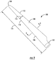
- FIG. 2 is a perspective view of an exemplary rotor blade in accordance with embodiments of the present disclosure
- FIG. 3 is a cross-sectional view of the rotor blade taken generally about line 3 - 3 shown in FIG. 2 , illustrating a shear web positioned within the rotor blade in accordance with embodiments of the present disclosure;
- FIG. 4 is a cross-sectional view of one embodiment of the shear web in accordance with embodiments of the present disclosure
- FIG. 5 is a cross-sectional view of a plurality of shear web members that couple together to form the shear web in accordance with embodiments of the present disclosure
- FIG. 6 is a cross-sectional view of one embodiment for coupling the shear web to a shell of the rotor blade in accordance with embodiments of the present disclosure
- FIG. 7 is a cross-sectional view of another embodiment for coupling the shear web to the shell of the rotor blade in accordance with embodiments of the present disclosure
- FIG. 8 is a cross-sectional view of yet another embodiment for coupling the shear web to a shell of the rotor blade in accordance with embodiments of the present disclosure
- FIG. 9 is a cross-sectional view of a further embodiment for coupling the shear web to a shell of the rotor blade in accordance with embodiments of the present disclosure.
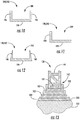
- FIG. 10 is a cross-sectional view of one embodiment of an end cap in accordance with embodiments of the present disclosure.
- FIG. 11 is a cross-sectional view of another embodiment of the end cap in accordance with embodiments of the present disclosure.
- FIG. 12 is a cross-sectional view of a further embodiment of the end cap in accordance with embodiments of the present disclosure.
- FIG. 13 is a cross-sectional view of an embodiment for coupling the shear web to a shell of the rotor blade using one or more spacers in accordance with embodiments of the present disclosure.
- FIG. 1 illustrates a perspective view of one embodiment of an exemplary wind turbine 10 in accordance with the present disclosure.
- the wind turbine 10 generally includes a tower 12 extending from a support surface 14 , a nacelle 16 mounted on the tower 12 , and a rotor 18 coupled to the nacelle 16 .
- the rotor 18 includes a rotatable hub 20 and at least one rotor blade 22 coupled to and extending outwardly from the hub 20 .
- the rotor 18 includes three rotor blades 22 . In alternative embodiments, however, the rotor 18 may include more or less than three rotor blades 22 .
- Each rotor blade 22 may be spaced about the hub 20 to facilitate rotating the rotor 18 to convert kinetic energy from the wind into usable mechanical energy, and subsequently, electrical energy.
- the hub 20 may be rotatably coupled to an electric generator 24 positioned within the nacelle 16 .
- FIG. 2 is a perspective view of a rotor blade 100 , which may be incorporated into the wind turbine 10 in place of or in addition to the rotor blade 22 .
- the rotor blade 100 includes a blade root 102 that couples to the rotatable hub 20 ( FIG. 1 ) and a blade tip 104 disposed opposite the blade root 102 .
- the rotor blade 100 may also include a pressure side 106 and a suction side 108 extending between a leading edge 110 and a trailing edge 112 .
- the rotor blade 100 may include a span 114 defining the total length between the blade root 102 and the blade tip 104 and a chord 116 defining the total length between the leading edge 110 and the trailing edge 112 .
- the chord 116 may vary in length along the span 114 as the rotor blade 100 extends from the blade root 102 to the blade tip 104 .
- the rotor blade 100 is formed from a shell 118 .
- the shell 118 includes a first shell portion 120 and a second shell portion 122 coupled (e.g., adhesively coupled) at or proximate to the leading edge 110 and the trailing edge 112 of the rotor blade 100 .
- the first and second shell portions 120 , 122 may extend along the entire span 114 and/or the entire chord 116 .
- the shell 118 may include more or fewer shell portions and/or the shell portions may be joined at different positions on the rotor blade 100 .
- each shell portion may in some embodiments extend for only a portion of the span 114 and/or the chord 116 .
- the shell 118 includes exterior surfaces defining the various sides and edges of the rotor blade 100 . More specifically, the first shell portion 120 includes an exterior surface 124 that defines the pressure side 106 of the rotor blade 100 . The second shell portion 122 includes an exterior surface 126 that defines the suction side 108 of the rotor blade 100 . In the embodiment shown in FIG. 3 , the first and second shell portions 120 , 122 couple together such that the second shell portion 122 defines the leading edge 110 and/or the first shell portion 120 defines the trailing edge 112 . In alternate embodiments, however, the first shell portion 120 may define the leading edge 110 , and the second shell portion 122 may define the trailing edge 112 . In further embodiments, the first and second shell portions 120 , 122 may both define the leading edge 110 and the trailing edge 112 .
- the shell 118 defines an interior cavity 128 therein. That is, the rotor blade 100 is generally hollow.
- the first shell portion defines an interior surface 130 and the second shell portion 122 defines an interior surface 132 .
- the interior surfaces 130 , 132 of the first and second shell portions 120 , 122 circumscribe the interior cavity 128 .
- Various structural components positioned in the interior cavity 128 may divide the interior cavity 128 into various compartments.
- the rotor blade 100 includes spar caps 134 , 136 positioned in the interior cavity 128 .
- a first spar cap 134 couples (e.g., adhesively) to the interior surface 130 of the first shell portion 120 .
- a second spar cap 136 couples (e.g., adhesively) to the interior surface 132 of the second shell portion 122 .
- the first and second spar caps 134 , 136 may generally resist bending stresses and/or other loads acting on the rotor blade 100 in a span-wise direction (i.e., a direction parallel to the span 114 of the rotor blade 100 ) during operation of a wind turbine 10 .
- first and second spar caps 134 , 136 may resist span-wise compression of the rotor blade 100 occurring during operation of the wind turbine 10 .
- the first and second spar caps 134 , 136 may extend along the span 114 from the blade root 102 to the blade tip 104 or a portion thereof.
- Some embodiments of the rotor blade 100 may include zero, one, three, four, or more spar caps.
- the rotor blade 100 further includes one or more shear webs 138 extending through the interior cavity 128 in the span-wise direction.
- the shear webs 138 may be formed via pultrusion.
- Each shear web 138 includes a first side 140 that couples to the first shell portion 120 and a second side 142 that couples to the second shell portion 122 .
- the shear webs 138 resist shear forces exerted on the first and second shell portions 120 , 122 .
- rotor blade 100 includes one shear web 138 directed connected (e.g., bonded) to first and second spar caps 134 , 136 .
- the rotor blade 100 may include more shear webs 138 and/or the shear webs 138 may be directly connected (e.g., bonded) to the interior surfaces 130 , 132 of the first and second shell portions 120 , 122 .
- the shear webs 138 may extend in the chord-wise direction (i.e., a direction parallel to the chord 116 of the rotor blade 100 ).
- FIG. 4 illustrates the shear web 138 in greater detail. More specifically, the shear web 138 may include a lattice structure 144 , which may form the entire shear web 138 or a portion thereof.
- a lattice structure is any structure that includes a periodically geometry having various interconnected walls defining a plurality of voids. In some embodiments, all of the walls of the lattice structure may have the same thickness. Furthermore, all of the voids in the lattice structure may be the same size and have the same shape in certain embodiments.
- the lattice structure 144 is a triangular lattice structure.
- the lattice structure 144 includes a first outer wall 146 spaced apart (e.g., in the chord-wise direction) from a second outer wall 148 .
- the first and second outer walls 146 , 148 extend between the first and second shell portions 120 , 122 ( FIG. 3 ) and along the span-wise direction.
- a plurality of perpendicular cross member walls 150 extends between (e.g., in the chord-wise direction) and couples to the first and second outer walls 146 , 148 .
- the perpendicular cross member walls 150 are evenly spaced apart between the first and second outer walls 146 , 148 , thereby forming a ladder-like configuration.
- a plurality of angular cross member walls 152 extends angularly between a junction of one of the perpendicular cross member walls 150 and one of the outer wall 146 , 148 and a junction of an adjacent perpendicular cross member wall 150 and the other outer wall 146 , 148 .
- the lattice structure 144 defines a plurality of triangular spaces 154 therein.
- the triangular spaces 154 are not filled with foam.
- the lattice structure 144 may be a honeycomb lattice or any other suitable lattice structure.
- first and second sides 140 , 142 of the shear web 138 couple to the first and second shell portions 120 , 122 of the rotor blade 100 .
- the first and second shell portions 120 , 122 may be curved along the chord-wise direction.
- one or more of the walls 146 , 148 , 150 , 152 may extend outwardly at the first and/or second sides 140 , 142 in a cantilever beam-like manner as shown in FIG. 4 .
- foam and/or end caps may be used to strengthen the first and second sides 140 , 142 in such embodiments.
- the shear web 138 may be formed from a plurality of shear web members. As shown, the shear web 138 may be formed from a first shear web member 156 having a first lattice structure portion 158 and a second shear web member 160 having a second lattice structure portion 162 .
- the first shear web member 156 includes a projection 164 at a first side 166 thereof and defines a slot 168 at a second side 170 thereof.
- the second shear web member 160 includes a projection 172 at a first side 174 thereof and defines a slot 176 at a second side 178 thereof.
- the slot 168 defined by the first shear web member 156 receives the projection 172 of the second shear web member 160 .
- Adhesive in the slot 168 may couple the first and second shear web members 156 , 160 .
- the projection 164 of the first shear web 156 member may be received a slot defined by another adjacent shear web member.
- the slot 176 on the second shear web member 160 may receive a projection from a further adjacent shear web member.
- any suitable number of shear web members may be coupled such that the shear web 138 extends between the first and second shell portions 120 , 122 and along the desired portion of the span 114 .
- the shear web members may be coupled in any other suitable manner.
- the shear web 138 and the associated lattice structure 144 may be formed from a suitable fiber reinforced polymer.
- the polymer may be reinforced with any suitable fiber material, including but not limited to glass fibers, carbon fibers, polymer fibers, ceramic fibers, nanofibers, metal fibers, or combinations thereof.
- the direction of the fibers may include biaxial, unidirectional, triaxial, or any other another suitable direction and/or combinations thereof.
- the fiber content may vary depending on the stiffness required in the corresponding blade component, the region, or location of the blade component in the rotor blade 100 .
- the shear web 138 and the associated lattice structure 144 may be produced using pultrusion.
- the terms “pultruded,” “pultrusions,” or similar generally encompass reinforced materials (e.g. fibers or woven or braided strands) that are impregnated with a resin and pulled through a stationary die such that the resin cures or undergoes polymerization.
- the process of manufacturing pultruded components is typically characterized by a continuous process of composite materials that produces composite parts having a constant cross-section.
- the pultruded components may be produced from rovings, which generally encompass long and narrow bundles of fibers that are not combined until joined by a cured resin.
- the pultruded shear web 138 and the associated lattice structure 144 may be cut to the desired shape and/or length using a water jet, a band saw, a diamond wire cutter, or any other suitable cutting device.
- the shear web 138 and the associated lattice structure 144 may be produced using additive manufacturing.
- additive manufacturing refers to any process which results in a useful, three-dimensional object and includes a step of sequentially forming the shape of the object one layer at a time.
- Additive manufacturing processes include three-dimensional printing (3DP) processes, direct thermoplastic material placement, automated fiber placement, automated tape placement, direct fiber reinforced thermoplastic, layered UV cured, etc.
- 3DP three-dimensional printing
- a particular type of additive manufacturing process uses rapid cure materials such as PET or ABS to solidify rapidly upon placement on top of preceding layers.
- Exemplary additive manufacturing processes for composites typically employ thermoplastic materials in raw pellet or spool form which can be liquefied, then placed in appropriate locations as the material solidifies.
- the shear web 138 and the associated lattice structure 144 may be produced using any suitable manufacturing method or process.
- FIGS. 6-10 illustrate various embodiments for coupling the shear web 138 to the first and the second shell portions 120 , 122 . Nevertheless, the shear web 138 may be coupled to the first and second shell portions 120 , 122 in any other suitable manner.
- FIGS. 6 and 7 illustrate embodiments for connecting the shear web 138 directly to the first and the second spar caps 134 , 136 or the first and the second shell portions 120 , 122 .
- FIGS. 6 and 7 show the shear web 138 coupled to a substrate 180 , which may be the first shell portion 120 , the second shell portion 122 , the first spar cap 134 , or the second spar cap 136 .
- the first and second sides 140 , 142 of shear web 138 are bonded to the substrate 180 via an adhesive 182 .
- the first and second sides 140 , 142 of shear web 138 are bonded to the substrate 180 via the adhesive 182 as shown in FIG. 6 .
- the first and second sides 140 , 142 of the shear web 138 have been filled with a foam 184 to stabilize the various walls of the lattice structure 144 acting a cantilever beam-like fashion.
- FIG. 8 illustrates another embodiment for coupling the shear web 138 to the spar caps 134 , 136 or the first and the second shell portions 120 , 122 that includes one or more shear clips 186 , 188 .
- the first and second sides 140 , 142 of the shear web 138 are connected to the first and the second spar caps 134 , 136 or the first and the second shell portions 120 , 122 via the adhesive 182 .
- the adhesive 182 bonds a first shear clip 186 to the first side 140 of the shear web 138 and to the first spar cap 134 or the first shell portion 120 .
- the adhesive 182 bonds a second shear clip 188 to the second side 142 of the shear web 138 and to the second spar cap 136 or the second shell portion 122 .
- the shear clips 186 , 188 may resist shear forces experienced by the adhesive 182 , thereby strengthening the connection between the shear web 138 and the first and the second spar caps 134 , 136 or the first and the second shell portions 120 , 122 .
- the first and second sides 140 , 142 of the shear web 138 may be filled with the foam 184 in embodiments that include the shear clips 186 , 188 .
- FIG. 9 illustrates a further embodiment for coupling the shear web 138 to the first and the second spar caps 134 , 136 or the first and the second shell portions 120 , 122 that includes one or more end caps 190 , 192 .
- a first end cap 190 is coupled to the first side 140 of the shear web 138 via, e.g., the adhesive 182 .
- a second end cap 192 is coupled to the second side 142 of the shear web 138 via, e.g., the adhesive 182 .
- the first and second end caps 190 , 192 support the various walls of the lattice structure 144 acting a cantilever beam-like fashion.
- the first and second end caps 190 , 192 may, in turn, be coupled to the first and the second spar caps 134 , 136 or the first and the second shell portions 120 , 122 , e.g., via additional adhesive 182 .
- the first and second end caps 190 , 192 may be coupled to the shear web 138 and the first and the second spar caps 134 , 136 or the first and the second shell portions 120 , 122 in any other suitable manner.
- FIGS. 10-12 illustrate various embodiments of the end caps 190 , 192 .
- the end caps 190 , 192 include a first wall 194 , a second wall 196 , and a third wall 198 .
- the second and third walls 196 , 198 are parallel and extend outward from the first wall 194 .
- the end cap 190 , 192 shown in FIG. 10 has a U-shape.
- the first, second, and third walls 194 , 196 , 198 collectively define a cavity 200 that receives the first or second side 140 , 142 of the shear web 138 .
- the first wall 194 couples to the shear web 138 and the first or second shell 120 , 122 , while the second and third walls 196 , 198 only couple to the shear web 138 .
- the first, second, and third walls 194 , 196 , 198 have rectangular cross-sections.
- the embodiment of the end caps 190 , 192 shown in FIG. 11 includes only the first and second walls 194 , 196 .
- the end cap 190 , 192 shown in FIG. 11 has an L-shape.
- the end caps 190 , 192 include the first, second, and third walls 194 , 196 , 198 like the embodiment shown in FIG. 10 .
- the second and third walls 196 , 198 have a triangular cross-sectional shape. Although the second and third walls 196 , 198 are shown as generally perpendicular to first wall 194 in FIGS. 10-12 , the first and second walls 196 , 198 may be oriented at an acute or obtuse angle relative to the first wall 194 to accommodate the curvature of rotor blade 100 . Furthermore, the end caps 190 , 192 may have any other suitable configuration in alternate embodiments.
- one or more spacers 202 may be used when coupling the shear web 138 to the first and the second spar caps 134 , 136 or the first and the second shell portions 120 , 122 . More specifically, the first side 140 of the shear web 138 is coupled to the first spar cap 134 or the first shell portion 120 using the first end cap 190 and the adhesive 182 as described above in the context of FIG. 9 . The adhesive 182 coupling the first side 140 of the shear web 138 and the first spar cap 134 or the first shell portion 120 is then cured. Similarly, the second end cap 192 couples to the spar cap 136 or the second side 122 of the shear web 138 via the adhesive 182 .
- the spacer 202 is coupled to the interior surface 132 of the second shell portion 122 via additional adhesive 182 . Further adhesive 182 is placed on the spacer 202 . The first and second shell portions 120 , 122 are then joined or otherwise coupled such that the second end cap 192 contacts the adhesive 182 on the spacer 202 . In this respect, the adhesive 182 couples the second side 142 of the shear web 138 , the second end cap 192 , the spacer 202 , and the second spar cap 136 or the second shell portion 122 together once the first and second shell portions 120 , 122 are joined. The adhesive 182 in contact with the spacer 202 is uncured when joining the first and second shell portions 120 , 122 .
- the use of the spacer 202 may eliminate the need to dry fit the shear web 138 with first and second shell portions 120 , 122 before coupling. That is, the spacer 202 may be used to fill gaps between the shear web 138 and the first and/or second shell portions 120 , 122 . In alternate embodiments, the shear web 138 may be coupled to second shell portion 122 via cured adhesive 182 before joining the first and second shell portion 120 , 122 .
- the shear web of the rotor blade 100 is formed partially or entirely of the lattice structure 144 .
- the incorporation of the lattice structure 144 in the shear web 138 reduces the time necessary to manufacture the shear web 138 relative to conventional shear webs. As such, the cost of manufacturing the shear web 138 and the rotor blade 100 is reduced compared to conventional shear webs and rotor blades.
Landscapes
- Engineering & Computer Science (AREA)
- Life Sciences & Earth Sciences (AREA)
- Sustainable Development (AREA)
- Sustainable Energy (AREA)
- Chemical & Material Sciences (AREA)
- Combustion & Propulsion (AREA)
- Mechanical Engineering (AREA)
- General Engineering & Computer Science (AREA)
- Wind Motors (AREA)
- Physics & Mathematics (AREA)
- Fluid Mechanics (AREA)
Abstract
Description
Claims (17)
Priority Applications (1)
| Application Number | Priority Date | Filing Date | Title |
|---|---|---|---|
| US15/367,472 US10690111B2 (en) | 2016-12-02 | 2016-12-02 | Wind turbine rotor blade |
Applications Claiming Priority (1)
| Application Number | Priority Date | Filing Date | Title |
|---|---|---|---|
| US15/367,472 US10690111B2 (en) | 2016-12-02 | 2016-12-02 | Wind turbine rotor blade |
Publications (2)
| Publication Number | Publication Date |
|---|---|
| US20180156190A1 US20180156190A1 (en) | 2018-06-07 |
| US10690111B2 true US10690111B2 (en) | 2020-06-23 |
Family
ID=62240878
Family Applications (1)
| Application Number | Title | Priority Date | Filing Date |
|---|---|---|---|
| US15/367,472 Active 2037-08-17 US10690111B2 (en) | 2016-12-02 | 2016-12-02 | Wind turbine rotor blade |
Country Status (1)
| Country | Link |
|---|---|
| US (1) | US10690111B2 (en) |
Families Citing this family (15)
| Publication number | Priority date | Publication date | Assignee | Title |
|---|---|---|---|---|
| GB201420833D0 (en) * | 2014-11-24 | 2015-01-07 | Blade Dynamics Ltd | A hub for a wind turbine |
| US11098691B2 (en) | 2017-02-03 | 2021-08-24 | General Electric Company | Methods for manufacturing wind turbine rotor blades and components thereof |
| US10830206B2 (en) | 2017-02-03 | 2020-11-10 | General Electric Company | Methods for manufacturing wind turbine rotor blades and components thereof |
| US11326575B2 (en) * | 2017-04-05 | 2022-05-10 | Vestas Wind Systems A/S | Wind turbine blade manufacture |
| US10821652B2 (en) | 2017-11-21 | 2020-11-03 | General Electric Company | Vacuum forming mold assembly and method for creating a vacuum forming mold assembly |
| US11390013B2 (en) | 2017-11-21 | 2022-07-19 | General Electric Company | Vacuum forming mold assembly and associated methods |
| US11040503B2 (en) | 2017-11-21 | 2021-06-22 | General Electric Company | Apparatus for manufacturing composite airfoils |
| US11248582B2 (en) | 2017-11-21 | 2022-02-15 | General Electric Company | Multiple material combinations for printed reinforcement structures of rotor blades |
| US10773464B2 (en) | 2017-11-21 | 2020-09-15 | General Electric Company | Method for manufacturing composite airfoils |
| US10865769B2 (en) | 2017-11-21 | 2020-12-15 | General Electric Company | Methods for manufacturing wind turbine rotor blade panels having printed grid structures |
| US10920745B2 (en) | 2017-11-21 | 2021-02-16 | General Electric Company | Wind turbine rotor blade components and methods of manufacturing the same |
| US11035339B2 (en) | 2018-03-26 | 2021-06-15 | General Electric Company | Shear web assembly interconnected with additive manufactured components |
| US10821696B2 (en) * | 2018-03-26 | 2020-11-03 | General Electric Company | Methods for manufacturing flatback airfoils for wind turbine rotor blades |
| MX2021002823A (en) * | 2018-09-11 | 2021-08-11 | Tpi Composites Inc | Positioning profiles for pultrusions in wind blade spar caps. |
| WO2022262916A1 (en) * | 2021-06-16 | 2022-12-22 | Vestas Wind Systems A/S | Shear web for a wind turbine blade and method of making same |
Citations (54)
| Publication number | Priority date | Publication date | Assignee | Title |
|---|---|---|---|---|
| US3771612A (en) | 1972-07-17 | 1973-11-13 | Pacific Tooling Eng Co | Replaceable wear-resistant element assembly |
| US3924839A (en) | 1972-11-20 | 1975-12-09 | Werner & Pfleiderer | Continuously operating screw conveyor |
| US3937123A (en) | 1974-04-08 | 1976-02-10 | Textron Inc. | Blind fastener with shear washer |
| US3959544A (en) | 1973-12-26 | 1976-05-25 | Rogers Charles W | Filamentary tape constructions and methods |
| US4162777A (en) | 1978-05-02 | 1979-07-31 | The United States Of America As Represented By The Secretary Of The Air Force | Canted spar with intermediate intercostal stiffeners |
| US4198018A (en) | 1978-03-13 | 1980-04-15 | The Boeing Company | Blended wing-fuselage frame made of fiber reinforced resin composites |
| US4295790A (en) * | 1979-06-21 | 1981-10-20 | The Budd Company | Blade structure for use in a windmill |
| US4546838A (en) | 1984-07-23 | 1985-10-15 | Ormond A Newman | Flexure isolated shear web load cell |
| US4920842A (en) | 1989-07-31 | 1990-05-01 | Eastman Kodak Company | Passive web cutter |
| US5027872A (en) | 1988-08-11 | 1991-07-02 | Imperial Chemical Industries Plc | System for introducing additive into a container |
| US5064705A (en) | 1989-08-28 | 1991-11-12 | United Technologies Corporation | Stabilizing laminate inserts for resin transfer molding |
| EP0457580A1 (en) | 1990-05-17 | 1991-11-21 | Shorfast Limited | Garment support rails |
| US5079121A (en) | 1989-12-29 | 1992-01-07 | Xerox Corporation | Seamless polymeric belts for electrophotography and processes for the preparation thereof |
| US5129787A (en) | 1991-02-13 | 1992-07-14 | United Technologies Corporation | Lightweight propulsor blade with internal spars and rigid base members |
| US5461933A (en) | 1994-02-04 | 1995-10-31 | Acutus Industries, Inc. | Shear web load cell having thermal compensation |
| US5472290A (en) | 1993-06-02 | 1995-12-05 | Altamont, Inc. | Joint with tapered edges |
| US5511677A (en) | 1995-03-30 | 1996-04-30 | The Procter & Gamble Company | Container having a tamper evidency system |
| EP0728858A1 (en) | 1995-02-23 | 1996-08-28 | MICHELE LETIZIA S.p.A. | A web or fabric having a variable thickness, a loom and a method for obtaining said web or fabric |
| US20030042050A1 (en) | 2001-09-06 | 2003-03-06 | Stimpson Jon L. | Tank weighing assembly with integrated tank mount and load cell |
| US20030116262A1 (en) * | 2001-11-13 | 2003-06-26 | Bonus Energy A/S | Method for manufacturing windmill blades |
| US20050013694A1 (en) | 2003-07-16 | 2005-01-20 | Kovalsky David A. | Rotor blade tip section |
| US20060237587A1 (en) | 2003-03-28 | 2006-10-26 | Airbus Deutschland Gmbh | Integral frame member for an aircraft |
| US20070041829A1 (en) | 2005-08-17 | 2007-02-22 | Laurent Bonnet | Rotor Blade for a Wind Energy Turbine |
| US20080219851A1 (en) | 2007-03-09 | 2008-09-11 | General Electric Company | Integrated shear webs for wind turbine blades |
| US20090087318A1 (en) | 2007-09-27 | 2009-04-02 | General Electric Company | Wind turbine spars with jointed shear webs |
| US20090196755A1 (en) * | 2004-07-12 | 2009-08-06 | Steven Peace | Modular Construction for Wind Turbine Blade |
| US20100008789A1 (en) * | 2007-01-16 | 2010-01-14 | Find Molholt Jensen | Reinforced blade for wind turbine |
| US20100028157A1 (en) | 2008-07-30 | 2010-02-04 | General Electric Company | Wind turbine blade tip shapes |
| US20100054950A1 (en) | 2008-08-29 | 2010-03-04 | General Electric Company | Wind turbine blades with cross webs |
| US20100068498A1 (en) | 2008-09-12 | 2010-03-18 | General Electric Company | Molded reinforced shear web cores |
| US20100135815A1 (en) * | 2009-02-20 | 2010-06-03 | General Electric Company | Spar cap for wind turbine blades |
| US20100209237A1 (en) | 2009-02-16 | 2010-08-19 | Rolls-Roycs Plc | Vane |
| US20100296940A1 (en) | 2009-05-21 | 2010-11-25 | Zuteck Michael D | Shell structure of wind turbine blade having regions of low shear modulus |
| US20110008175A1 (en) * | 2009-07-07 | 2011-01-13 | Nordex Energy Gmbh | Rotor blade for a wind turbine and method for its production |
| US7922454B1 (en) | 2010-10-29 | 2011-04-12 | General Electric Company | Joint design for rotor blade segments of a wind turbine |
| US20110126978A1 (en) | 2009-05-29 | 2011-06-02 | Nordex Energy Gmbh | Method and apparatus for assembling a rotor blade for a wind turbine |
| US20110176928A1 (en) * | 2008-06-23 | 2011-07-21 | Jensen Find Moelholt | Wind turbine blade with angled girders |
| US20110187115A1 (en) | 2010-04-09 | 2011-08-04 | Frederick W Piasecki | Highly Reliable, Low Cost Wind Turbine Rotor Blade |
| US20110229333A1 (en) | 2010-03-22 | 2011-09-22 | Repower Systems Ag | Shear web connection |
| US20120027613A1 (en) * | 2011-07-19 | 2012-02-02 | General Electric Company | Wind turbine blade shear web connection assembly |
| US20120027612A1 (en) | 2011-07-19 | 2012-02-02 | General Electric Company | Wind turbine blade shear web connection assembly |
| US20120027614A1 (en) | 2011-07-19 | 2012-02-02 | General Electric Company | Wind turbine blade multi-component shear web with intermediate connection assembly |
| US20120027610A1 (en) * | 2011-06-08 | 2012-02-02 | General Electric Company | Wind turbine blade shear web with spring flanges |
| US20120033207A1 (en) | 2011-07-28 | 2012-02-09 | General Electric Company | Composite fiber wave inspection system and method |
| US8272687B2 (en) | 2006-06-23 | 2012-09-25 | Johnson Controls Gmbh | Vehicle seat having an anti-submarining device and method |
| US20120255669A1 (en) | 2011-04-11 | 2012-10-11 | Philip Catsman | Method for manufacturing large molded monolithic products |
| US20130183161A1 (en) * | 2012-01-18 | 2013-07-18 | Pika Energy LLC | Low-Cost Molded Wind Turbine Blade |
| US20140334930A1 (en) * | 2011-12-22 | 2014-11-13 | Lm Wp Patent Holding A/S | Wind turbine blade assembled from inboard part and outboard part having different types of load carrying structures |
| US20150308404A1 (en) * | 2012-12-18 | 2015-10-29 | Lm Wp Patent Holding A/S | A wind turbine blade comprising an aerodynamic blade shell with recess and pre-manufactured spar cap |
| US20150316028A1 (en) * | 2014-05-01 | 2015-11-05 | Zachary Brekenfeld | Wind turbine rotor blade and method of construction |
| US20170021575A1 (en) * | 2013-12-03 | 2017-01-26 | Lm Wp Patent Holding A/S | A method of manufacturing a shear web using a pre-formed web foot flange |
| US20170030330A1 (en) * | 2015-07-30 | 2017-02-02 | General Electric Company | Rotor blade with interior shelf for a flat plate spar cap |
| US20170050372A1 (en) * | 2014-05-01 | 2017-02-23 | Lm Wp Patent Holding A/S | System and method of manufacturing a wind turbine blade |
| US20170241401A1 (en) * | 2014-08-12 | 2017-08-24 | Vestas Wind Systems A/S | Improvements relating to wind turbine blade manufacture |
-
2016
- 2016-12-02 US US15/367,472 patent/US10690111B2/en active Active
Patent Citations (72)
| Publication number | Priority date | Publication date | Assignee | Title |
|---|---|---|---|---|
| US3771612A (en) | 1972-07-17 | 1973-11-13 | Pacific Tooling Eng Co | Replaceable wear-resistant element assembly |
| US3924839A (en) | 1972-11-20 | 1975-12-09 | Werner & Pfleiderer | Continuously operating screw conveyor |
| US3959544A (en) | 1973-12-26 | 1976-05-25 | Rogers Charles W | Filamentary tape constructions and methods |
| US3937123A (en) | 1974-04-08 | 1976-02-10 | Textron Inc. | Blind fastener with shear washer |
| US4198018A (en) | 1978-03-13 | 1980-04-15 | The Boeing Company | Blended wing-fuselage frame made of fiber reinforced resin composites |
| US4162777A (en) | 1978-05-02 | 1979-07-31 | The United States Of America As Represented By The Secretary Of The Air Force | Canted spar with intermediate intercostal stiffeners |
| US4295790A (en) * | 1979-06-21 | 1981-10-20 | The Budd Company | Blade structure for use in a windmill |
| US4546838A (en) | 1984-07-23 | 1985-10-15 | Ormond A Newman | Flexure isolated shear web load cell |
| US5027872A (en) | 1988-08-11 | 1991-07-02 | Imperial Chemical Industries Plc | System for introducing additive into a container |
| US4920842A (en) | 1989-07-31 | 1990-05-01 | Eastman Kodak Company | Passive web cutter |
| US5064705A (en) | 1989-08-28 | 1991-11-12 | United Technologies Corporation | Stabilizing laminate inserts for resin transfer molding |
| US5079121A (en) | 1989-12-29 | 1992-01-07 | Xerox Corporation | Seamless polymeric belts for electrophotography and processes for the preparation thereof |
| EP0457580A1 (en) | 1990-05-17 | 1991-11-21 | Shorfast Limited | Garment support rails |
| US5129787A (en) | 1991-02-13 | 1992-07-14 | United Technologies Corporation | Lightweight propulsor blade with internal spars and rigid base members |
| US5472290A (en) | 1993-06-02 | 1995-12-05 | Altamont, Inc. | Joint with tapered edges |
| US5461933A (en) | 1994-02-04 | 1995-10-31 | Acutus Industries, Inc. | Shear web load cell having thermal compensation |
| EP0728858A1 (en) | 1995-02-23 | 1996-08-28 | MICHELE LETIZIA S.p.A. | A web or fabric having a variable thickness, a loom and a method for obtaining said web or fabric |
| US5511677A (en) | 1995-03-30 | 1996-04-30 | The Procter & Gamble Company | Container having a tamper evidency system |
| US6596949B2 (en) | 2001-09-06 | 2003-07-22 | Jon L. Stimpson | Tank weighing assembly with integrated tank mount and load cell |
| US20030042050A1 (en) | 2001-09-06 | 2003-03-06 | Stimpson Jon L. | Tank weighing assembly with integrated tank mount and load cell |
| US20030116262A1 (en) * | 2001-11-13 | 2003-06-26 | Bonus Energy A/S | Method for manufacturing windmill blades |
| US7686249B2 (en) | 2003-03-28 | 2010-03-30 | Airbus Deutschland Gmbh | Integral frame member for an aircraft |
| US20060237587A1 (en) | 2003-03-28 | 2006-10-26 | Airbus Deutschland Gmbh | Integral frame member for an aircraft |
| US20050013694A1 (en) | 2003-07-16 | 2005-01-20 | Kovalsky David A. | Rotor blade tip section |
| US6976829B2 (en) | 2003-07-16 | 2005-12-20 | Sikorsky Aircraft Corporation | Rotor blade tip section |
| US20090196755A1 (en) * | 2004-07-12 | 2009-08-06 | Steven Peace | Modular Construction for Wind Turbine Blade |
| US20070041829A1 (en) | 2005-08-17 | 2007-02-22 | Laurent Bonnet | Rotor Blade for a Wind Energy Turbine |
| US7470114B2 (en) | 2005-08-17 | 2008-12-30 | General Electric Company | Rotor blade for a wind energy turbine |
| US8272687B2 (en) | 2006-06-23 | 2012-09-25 | Johnson Controls Gmbh | Vehicle seat having an anti-submarining device and method |
| US20100008789A1 (en) * | 2007-01-16 | 2010-01-14 | Find Molholt Jensen | Reinforced blade for wind turbine |
| US20080219851A1 (en) | 2007-03-09 | 2008-09-11 | General Electric Company | Integrated shear webs for wind turbine blades |
| US20110142669A1 (en) | 2007-03-09 | 2011-06-16 | General Electric Company | Integrated shear webs for wind turbine blades |
| US7895745B2 (en) | 2007-03-09 | 2011-03-01 | General Electric Company | Method for fabricating elongated airfoils for wind turbines |
| US20090087318A1 (en) | 2007-09-27 | 2009-04-02 | General Electric Company | Wind turbine spars with jointed shear webs |
| US8075275B2 (en) * | 2007-09-27 | 2011-12-13 | General Electric Company | Wind turbine spars with jointed shear webs |
| US20110176928A1 (en) * | 2008-06-23 | 2011-07-21 | Jensen Find Moelholt | Wind turbine blade with angled girders |
| US20100028157A1 (en) | 2008-07-30 | 2010-02-04 | General Electric Company | Wind turbine blade tip shapes |
| US7854595B2 (en) | 2008-07-30 | 2010-12-21 | General Electric Company | Wind turbine blade tip shapes |
| US20100054950A1 (en) | 2008-08-29 | 2010-03-04 | General Electric Company | Wind turbine blades with cross webs |
| US7866951B2 (en) | 2008-08-29 | 2011-01-11 | General Electric Company | Wind turbine blades with cross webs |
| US20100068498A1 (en) | 2008-09-12 | 2010-03-18 | General Electric Company | Molded reinforced shear web cores |
| US7857595B2 (en) | 2008-09-12 | 2010-12-28 | General Electric Company | Molded reinforced shear web cores |
| US20100209237A1 (en) | 2009-02-16 | 2010-08-19 | Rolls-Roycs Plc | Vane |
| US7841835B2 (en) | 2009-02-20 | 2010-11-30 | General Electric Company | Spar cap for wind turbine blades |
| US20100135815A1 (en) * | 2009-02-20 | 2010-06-03 | General Electric Company | Spar cap for wind turbine blades |
| US8075278B2 (en) | 2009-05-21 | 2011-12-13 | Zuteck Michael D | Shell structure of wind turbine blade having regions of low shear modulus |
| US20100296940A1 (en) | 2009-05-21 | 2010-11-25 | Zuteck Michael D | Shell structure of wind turbine blade having regions of low shear modulus |
| US20110126978A1 (en) | 2009-05-29 | 2011-06-02 | Nordex Energy Gmbh | Method and apparatus for assembling a rotor blade for a wind turbine |
| US20110008175A1 (en) * | 2009-07-07 | 2011-01-13 | Nordex Energy Gmbh | Rotor blade for a wind turbine and method for its production |
| US20110229333A1 (en) | 2010-03-22 | 2011-09-22 | Repower Systems Ag | Shear web connection |
| US20110187115A1 (en) | 2010-04-09 | 2011-08-04 | Frederick W Piasecki | Highly Reliable, Low Cost Wind Turbine Rotor Blade |
| US20120180582A1 (en) | 2010-04-09 | 2012-07-19 | Piasecki Frederick W | Highly Reliabile, Low Cost Wind Turbine Rotor Blade |
| US8192169B2 (en) | 2010-04-09 | 2012-06-05 | Frederick W Piasecki | Highly reliable, low cost wind turbine rotor blade |
| US20120174401A1 (en) | 2010-04-09 | 2012-07-12 | Piasecki Frederick W | Highly Reliable, Low Cost Wind Turbine Rotor Blade |
| US7922454B1 (en) | 2010-10-29 | 2011-04-12 | General Electric Company | Joint design for rotor blade segments of a wind turbine |
| US20120255669A1 (en) | 2011-04-11 | 2012-10-11 | Philip Catsman | Method for manufacturing large molded monolithic products |
| US20120027610A1 (en) * | 2011-06-08 | 2012-02-02 | General Electric Company | Wind turbine blade shear web with spring flanges |
| US8262362B2 (en) | 2011-06-08 | 2012-09-11 | General Electric Company | Wind turbine blade shear web with spring flanges |
| US20120027613A1 (en) * | 2011-07-19 | 2012-02-02 | General Electric Company | Wind turbine blade shear web connection assembly |
| US8235671B2 (en) | 2011-07-19 | 2012-08-07 | General Electric Company | Wind turbine blade shear web connection assembly |
| US8257048B2 (en) | 2011-07-19 | 2012-09-04 | General Electric Company | Wind turbine blade multi-component shear web with intermediate connection assembly |
| US20120027614A1 (en) | 2011-07-19 | 2012-02-02 | General Electric Company | Wind turbine blade multi-component shear web with intermediate connection assembly |
| US20120027612A1 (en) | 2011-07-19 | 2012-02-02 | General Electric Company | Wind turbine blade shear web connection assembly |
| US20120033207A1 (en) | 2011-07-28 | 2012-02-09 | General Electric Company | Composite fiber wave inspection system and method |
| US20140334930A1 (en) * | 2011-12-22 | 2014-11-13 | Lm Wp Patent Holding A/S | Wind turbine blade assembled from inboard part and outboard part having different types of load carrying structures |
| US20130183161A1 (en) * | 2012-01-18 | 2013-07-18 | Pika Energy LLC | Low-Cost Molded Wind Turbine Blade |
| US20150308404A1 (en) * | 2012-12-18 | 2015-10-29 | Lm Wp Patent Holding A/S | A wind turbine blade comprising an aerodynamic blade shell with recess and pre-manufactured spar cap |
| US20170021575A1 (en) * | 2013-12-03 | 2017-01-26 | Lm Wp Patent Holding A/S | A method of manufacturing a shear web using a pre-formed web foot flange |
| US20150316028A1 (en) * | 2014-05-01 | 2015-11-05 | Zachary Brekenfeld | Wind turbine rotor blade and method of construction |
| US20170050372A1 (en) * | 2014-05-01 | 2017-02-23 | Lm Wp Patent Holding A/S | System and method of manufacturing a wind turbine blade |
| US20170241401A1 (en) * | 2014-08-12 | 2017-08-24 | Vestas Wind Systems A/S | Improvements relating to wind turbine blade manufacture |
| US20170030330A1 (en) * | 2015-07-30 | 2017-02-02 | General Electric Company | Rotor blade with interior shelf for a flat plate spar cap |
Also Published As
| Publication number | Publication date |
|---|---|
| US20180156190A1 (en) | 2018-06-07 |
Similar Documents
| Publication | Publication Date | Title |
|---|---|---|
| US10690111B2 (en) | Wind turbine rotor blade | |
| US10465653B2 (en) | Wind turbine blade with hybrid spar cap and associated method for making | |
| CN109098929B (en) | Wind turbine blade with hybrid spar cap and associated method of manufacture | |
| US11752709B2 (en) | Reinforcing structure for a wind turbine blade | |
| US8753092B2 (en) | Rotor blade for a wind turbine and methods of manufacturing the same | |
| CN106368893B (en) | Rotor blade root assembly for a wind turbine | |
| US10316817B2 (en) | Wind turbine blade and an associated manufacturing method | |
| CN205330872U (en) | Rotor blade component and rotor blade | |
| US20160146185A1 (en) | Methods for manufacturing a spar cap for a wind turbine rotor blade | |
| US20140271217A1 (en) | Efficient wind turbine blade design and associated manufacturing methods using rectangular spars and segmented shear web | |
| US9403335B2 (en) | Wind turbine rotor blade with trailing edge comprising rovings | |
| US20160040651A1 (en) | Methods of manufacturing rotor blades of a wind turbine | |
| CN106368894A (en) | Rotor blade root assembly for wind turbine | |
| CN106662070A (en) | Tip systems for wind turbine blades | |
| CN105799184A (en) | Methods of manufacturing rotor blade components for a wind turbine | |
| EP3436256B1 (en) | Rotor blade tip mold assembly including expandable bladders and method for forming rotor blade tip | |
| CN114930015A (en) | Equipotential bonding of wind turbine rotor blades | |
| CN115666913A (en) | Pultruded fiber reinforced strips for reinforced structures such as spar caps | |
| EP3032094B1 (en) | Spar cap for a wind turbine rotor blade | |
| EP3436252B1 (en) | Rotor blade tip mold assembly including solid core and method for forming rotor blade tip | |
| CN116917113A (en) | Guidance member for guiding the shear web of a wind turbine blade | |
| CN117616196A (en) | wind turbine blades | |
| US20240295210A1 (en) | A blade for a wind turbine |
Legal Events
| Date | Code | Title | Description |
|---|---|---|---|
| AS | Assignment |
Owner name: GENERAL ELECTRIC COMPANY, NEW YORK Free format text: ASSIGNMENT OF ASSIGNORS INTEREST;ASSIGNORS:JOHNSON, STEPHEN BERTRAM;KYRIAKIDES, ANNE PARSONS;SIGNING DATES FROM 20161101 TO 20161112;REEL/FRAME:040494/0569 |
|
| STPP | Information on status: patent application and granting procedure in general |
Free format text: FINAL REJECTION MAILED |
|
| STPP | Information on status: patent application and granting procedure in general |
Free format text: RESPONSE AFTER FINAL ACTION FORWARDED TO EXAMINER |
|
| STPP | Information on status: patent application and granting procedure in general |
Free format text: NON FINAL ACTION MAILED |
|
| STPP | Information on status: patent application and granting procedure in general |
Free format text: RESPONSE TO NON-FINAL OFFICE ACTION ENTERED AND FORWARDED TO EXAMINER |
|
| STPP | Information on status: patent application and granting procedure in general |
Free format text: FINAL REJECTION MAILED |
|
| STPP | Information on status: patent application and granting procedure in general |
Free format text: DOCKETED NEW CASE - READY FOR EXAMINATION |
|
| STPP | Information on status: patent application and granting procedure in general |
Free format text: NOTICE OF ALLOWANCE MAILED -- APPLICATION RECEIVED IN OFFICE OF PUBLICATIONS |
|
| STPP | Information on status: patent application and granting procedure in general |
Free format text: PUBLICATIONS -- ISSUE FEE PAYMENT RECEIVED |
|
| STCF | Information on status: patent grant |
Free format text: PATENTED CASE |
|
| AS | Assignment |
Owner name: GE INFRASTRUCTURE TECHNOLOGY LLC, SOUTH CAROLINA Free format text: ASSIGNMENT OF ASSIGNORS INTEREST;ASSIGNOR:GENERAL ELECTRIC COMPANY;REEL/FRAME:065727/0001 Effective date: 20231110 |
|
| MAFP | Maintenance fee payment |
Free format text: PAYMENT OF MAINTENANCE FEE, 4TH YEAR, LARGE ENTITY (ORIGINAL EVENT CODE: M1551); ENTITY STATUS OF PATENT OWNER: LARGE ENTITY Year of fee payment: 4 |