EP2272047B1 - 3d-bildgebungssystem - Google Patents
3d-bildgebungssystem Download PDFInfo
- Publication number
- EP2272047B1 EP2272047B1 EP09727607A EP09727607A EP2272047B1 EP 2272047 B1 EP2272047 B1 EP 2272047B1 EP 09727607 A EP09727607 A EP 09727607A EP 09727607 A EP09727607 A EP 09727607A EP 2272047 B1 EP2272047 B1 EP 2272047B1
- Authority
- EP
- European Patent Office
- Prior art keywords
- template
- viewpoints
- images
- templates
- localisation
- Prior art date
- Legal status (The legal status is an assumption and is not a legal conclusion. Google has not performed a legal analysis and makes no representation as to the accuracy of the status listed.)
- Active
Links
- 238000003384 imaging method Methods 0.000 title claims abstract description 58
- 230000004807 localization Effects 0.000 claims abstract description 70
- 238000000034 method Methods 0.000 claims abstract description 46
- 230000003287 optical effect Effects 0.000 claims abstract description 17
- 238000005286 illumination Methods 0.000 claims description 15
- 238000001914 filtration Methods 0.000 claims description 7
- 238000004458 analytical method Methods 0.000 claims description 4
- 238000012545 processing Methods 0.000 description 24
- 239000000463 material Substances 0.000 description 22
- 238000013459 approach Methods 0.000 description 14
- 238000002310 reflectometry Methods 0.000 description 14
- 230000006870 function Effects 0.000 description 12
- 238000005259 measurement Methods 0.000 description 9
- 238000011084 recovery Methods 0.000 description 9
- 238000007689 inspection Methods 0.000 description 8
- 238000013507 mapping Methods 0.000 description 7
- 230000008901 benefit Effects 0.000 description 6
- 230000009466 transformation Effects 0.000 description 6
- 238000004891 communication Methods 0.000 description 5
- 230000008569 process Effects 0.000 description 5
- 230000010354 integration Effects 0.000 description 4
- 239000011159 matrix material Substances 0.000 description 4
- 230000004044 response Effects 0.000 description 4
- 238000005070 sampling Methods 0.000 description 4
- 238000000844 transformation Methods 0.000 description 4
- 230000000295 complement effect Effects 0.000 description 3
- 238000012937 correction Methods 0.000 description 3
- 238000000605 extraction Methods 0.000 description 3
- 230000004927 fusion Effects 0.000 description 3
- 238000004519 manufacturing process Methods 0.000 description 3
- 238000001454 recorded image Methods 0.000 description 3
- 238000009877 rendering Methods 0.000 description 3
- 230000008859 change Effects 0.000 description 2
- 230000001427 coherent effect Effects 0.000 description 2
- 238000011960 computer-aided design Methods 0.000 description 2
- 238000011065 in-situ storage Methods 0.000 description 2
- 239000003550 marker Substances 0.000 description 2
- 230000005855 radiation Effects 0.000 description 2
- 238000001228 spectrum Methods 0.000 description 2
- 230000003068 static effect Effects 0.000 description 2
- 206010011409 Cross infection Diseases 0.000 description 1
- 206010029803 Nosocomial infection Diseases 0.000 description 1
- 238000012550 audit Methods 0.000 description 1
- 238000013474 audit trail Methods 0.000 description 1
- 230000002457 bidirectional effect Effects 0.000 description 1
- 238000013481 data capture Methods 0.000 description 1
- 238000001514 detection method Methods 0.000 description 1
- 238000011161 development Methods 0.000 description 1
- 238000002059 diagnostic imaging Methods 0.000 description 1
- 238000009826 distribution Methods 0.000 description 1
- 238000005315 distribution function Methods 0.000 description 1
- 230000000694 effects Effects 0.000 description 1
- 230000005670 electromagnetic radiation Effects 0.000 description 1
- 238000010304 firing Methods 0.000 description 1
- 238000010348 incorporation Methods 0.000 description 1
- 238000007726 management method Methods 0.000 description 1
- 238000003032 molecular docking Methods 0.000 description 1
- 239000000523 sample Substances 0.000 description 1
- 230000035945 sensitivity Effects 0.000 description 1
- 230000003595 spectral effect Effects 0.000 description 1
- 238000010561 standard procedure Methods 0.000 description 1
- 238000003860 storage Methods 0.000 description 1
- 230000001360 synchronised effect Effects 0.000 description 1
- 238000001429 visible spectrum Methods 0.000 description 1
- 229910052724 xenon Inorganic materials 0.000 description 1
- FHNFHKCVQCLJFQ-UHFFFAOYSA-N xenon atom Chemical compound [Xe] FHNFHKCVQCLJFQ-UHFFFAOYSA-N 0.000 description 1
Images
Classifications
-
- G—PHYSICS
- G06—COMPUTING; CALCULATING OR COUNTING
- G06T—IMAGE DATA PROCESSING OR GENERATION, IN GENERAL
- G06T7/00—Image analysis
- G06T7/50—Depth or shape recovery
- G06T7/55—Depth or shape recovery from multiple images
-
- G—PHYSICS
- G06—COMPUTING; CALCULATING OR COUNTING
- G06T—IMAGE DATA PROCESSING OR GENERATION, IN GENERAL
- G06T7/00—Image analysis
- G06T7/50—Depth or shape recovery
-
- G—PHYSICS
- G06—COMPUTING; CALCULATING OR COUNTING
- G06T—IMAGE DATA PROCESSING OR GENERATION, IN GENERAL
- G06T7/00—Image analysis
- G06T7/50—Depth or shape recovery
- G06T7/55—Depth or shape recovery from multiple images
- G06T7/586—Depth or shape recovery from multiple images from multiple light sources, e.g. photometric stereo
-
- G—PHYSICS
- G06—COMPUTING; CALCULATING OR COUNTING
- G06T—IMAGE DATA PROCESSING OR GENERATION, IN GENERAL
- G06T7/00—Image analysis
- G06T7/50—Depth or shape recovery
- G06T7/55—Depth or shape recovery from multiple images
- G06T7/593—Depth or shape recovery from multiple images from stereo images
-
- G—PHYSICS
- G06—COMPUTING; CALCULATING OR COUNTING
- G06T—IMAGE DATA PROCESSING OR GENERATION, IN GENERAL
- G06T2200/00—Indexing scheme for image data processing or generation, in general
- G06T2200/08—Indexing scheme for image data processing or generation, in general involving all processing steps from image acquisition to 3D model generation
-
- G—PHYSICS
- G06—COMPUTING; CALCULATING OR COUNTING
- G06T—IMAGE DATA PROCESSING OR GENERATION, IN GENERAL
- G06T2207/00—Indexing scheme for image analysis or image enhancement
- G06T2207/30—Subject of image; Context of image processing
- G06T2207/30204—Marker
Definitions
- the present invention relates to an apparatus and method for obtaining three dimensional (3D) images.
- the invention relates to 3D imaging and measurement of the surfaces of objects.
- 3D imaging is the acquisition into digital form of geometry (physical shape) of a surface region of a real object.
- the material reflectivity properties of the object may also be acquired.
- a surface region of an object can be considered to be a subregion of the physical surface of an object.
- the system can be extended to include imaging of extensive surface regions, meaning that the system is able to acquire a region larger than that obtainable by the imaging device from a single viewing position (for example the surface region on more than one side of a 3D object).
- the system may capture part, or all, of the surface shape and material characteristics of an object or scene as well as the shape's metric properties. Examples of material reflectivity properties include diffuse surface colour, and a measure of the quantity of specular reflection exhibited by the material, both as an absolute value and by spectral component.
- 3D imaging can be found in a wide variety of areas, such as imaging of the human body for medical purposes, capturing data for rendering in production of video games and film, architectural model capture, reverse engineering for computer aided design (CAD), and data capture for archival purposes, such as archaeology.
- CAD computer aided design
- Various systems are known for the 3D acquisition of the shape of an object, but typical existing systems exhibit one or more of the following limitations in this regard:
- the present system aims to alleviate, at least partially, the issues above.
- a portable, hand-held instrument for computing a three dimensional model of an object.
- the apparatus comprises a portable, hand-held instrument comprising multiple directional energy sources arranged to directionally illuminate the object.
- the instrument also includes an imaging assembly, having at least two spatially separated viewpoints at fixed positions relative to each other, and arranged to record a series of images of the object at each viewpoint when the object is illuminated by each source. At least one localisation template having predetermined geometrical features is visible to at least one of the viewpoints simultaneously with the object.
- a processor is arranged to analyse the images recorded at the viewpoints, so as to determine the location and pose of each viewpoint relative to the template, for each image in the series of images, and generate photometric data for the object using the calculated location and pose of the viewpoints, together with the Image data and the direction of Illumination from the energy source.
- the processor is further arranged to generate geometric data comprising a skeleton three dimensional model of the object by performing stereoscopic reconstruction using optical triangulation so as to provide the gross-scale shape of the object, and combine the geometric data and photometric data by using the photometric data to provide high-frequency geometric detail onto the gross-scale shape so as to construct the three dimensional model.
- the apparatus is capable of providing at least two separated viewpoints of the object.
- this is often referred to as a 'stereo pair', although it will be appreciated that more than two viewpoints may also be used, and this may increase the precision and/or visible range of the apparatus.
- the words "stereo" and “stereoscopic” as used herein are intended to encompass the processing of images from two, or three or more, viewpoints, and not intended to restrict the disclosure to paired viewpoints only.
- the directional energy sources may be, for example, a standard photographic flash, a high brightness LED cluster, or Xenon flash bulb or a 'ring flash', although it will be appreciated that the energy need not be in the visible light spectrum.
- the sources may comprise any method of generating directional energy, such as electromagnetic radiation, which will hereinafter be referred to as 'light', it being understood that this is not restricted to radiation in the visible spectrum.
- Appropriate optical filtering, such as polarising filters, for example, may preferably be included with the sources and/or image sensing assembly to reduce visibility of direct reflections of the directional source(s) at the viewpoints.
- sensors may be provided at the viewpoints including, for example, two or more standard digital cameras, or video cameras, or CMOS sensors and lenses appropriately mounted. In the case of other types of directional energy, sensors appropriate for the directional energy used are adopted. A discrete sensor may be placed at each viewpoint, or in another alternative a single sensor may be located behind a split lens.
- the direction of illumination may be known relative to the viewpoints. This can be achieved, for example, if the multiple energy sources are fixed relative to the viewpoints.
- the localisation template(s) must be illuminated by the sources, as well as being visible to at least one of the viewpoints, in each image of the series of images.
- the source may be moved between Images in the series of images, in which case the localisation template may be used to identify the direction of illumination.
- the template or templates preferably comprise a predetermined set of geometric features (for example a printed pattern) such that the relative position of the imaging device and the template can be determined by imaging the template.
- Features of the pattern can be designed to act as highly exciting beacons for image processing algorithms.
- a light source localisation feature of known dimensions may also be provided for facilitating the computation of the relative position of the source(s) with respect to the templates. This may be, for example, a cone or pyramid of known dimensions.
- the template may also include a colour calibration portion for facilitating colour response calibration and/or correction in the imaging device.
- Each template may also optionally incorporate one or more unique features allowing an individual template to be uniquely identified in an automated manner; one example of this is a printed 1D or 2D 'bar-code'. Another example of this is inclusion of a Radio Frequency Identification Device, or 'RFID tag'. Another example might be inclusion of one or more retro-reflective markers arranged in a pattern. A further example is the inclusion of an embedded EEPROM chip or similar In the template. Any of these features may be used as a "key" linking the recorded images to the object and / or ensuring a single use of the template.
- the template may incorporate additional markers that enable automatic recognition and / or measurement against a metric standard.
- a short-range RFID tag transceiver allows communication between templates incorporating the RFID tag and the rest of the apparatus.
- interface hardware in the apparatus allows communication between templates incorporating EEPROM chips or similar and the rest of the apparatus.
- the unique identification features may be also be included on templates to be used with other 3D image acquisition systems. Therefore in accordance with another aspect of the present invention there is provided an apparatus for computing a three dimensional model of an object, comprising at least one image scanner arranged to generate at least one 3D model of the object.
- the apparatus also includes at least one localisation template having predetermined geometrical features and a unique identification feature enabling the template to be distinguished from other templates.
- the localisation template is arranged when in use to be detectable by the scanner simultaneously with the object.
- a processor is arranged to analyse the image or images recorded by the sensor, so as to construct the three dimensional model.
- the invention also provides a localisation template having such a unique identification feature.
- the apparatus includes a plurality of localisation templates.
- the sensors and source may be locatable in a first location in which at least two first templates are visible to the sensors simultaneously with a first portion of the object, and movable to a second location in which at least one of the at least two first templates is still visible to the sensors simultaneously with at least one other template and a second portion of the object overlapping with the first portion.
- the sensors record images from both locations, and the data from the images is combined so as to generate a model covering the first and second portions of the object.
- multiple templates enables images of overlapping portions of a large object to be used to build up an image of a larger portion of the object than would otherwise be possible.
- multiple templates may also be used with other methods of obtaining geometric data (e.g . a laser striper) and their use is not restricted to the arrangement using passive stereo.
- the processor preferably includes means to store images from the imaging device and carry out certain image processing functions, 3D reconstruction and representation of the surface or object under inspection, and other functions such as: reconstruction of any separate illumination conditions, extraction of a metric standard, extraction of a colour standard, extraction and recording of a unique identifier, and enforcing single use for a template.
- image processing functions 3D reconstruction and representation of the surface or object under inspection
- other functions such as: reconstruction of any separate illumination conditions, extraction of a metric standard, extraction of a colour standard, extraction and recording of a unique identifier, and enforcing single use for a template.
- this might be a desktop or laptop PC with monitor, hard disk, and all other common components
- the system adopts metrological principles, so that, at least in preferred embodiments: measurements are made with respect to standard templates' that are, in principle, traceable to superior metrological standards; all imaging is carried out using a fixed coordinate datum or set of coordinate data; all calibration of the system can, in principle, be carried out using 'templates' as reference objects.
- a particular characteristic of one embodiment of the system is the ability to effectively handle large surface areas that cannot be accommodated in a single camera view of the scene.
- the combination of passive stereoscopic geometric data and photometric data removes the need for patterned light such as laser stripe projection.
- the system is suitable for portable capture, i.e. it may be movable to an object or extensive surface so that it can be captured 'in situ'.
- a series of images of the surface are preferably captured with one or more templates placed on or around the surface such that they may be imaged simultaneously with the surface.
- a set of stereo images are acquired by moving the directional source and firing the directional source synchronized with stereo (two or more viewpoint) image capture. If the directional source is light, then such images are called stereo photometric images. Processing is then carried out (potentially 'off-line' after capture) to reconstruct the surface under inspection.
- a photometric reconstruction of the surface area being acquired may be performed by processing a set of images having varying directional lighting from one 'side' of the two stereo viewpoints.
- a passive stereoscopic reconstruction of the surface area being acquired may be performed by processing one or more stereo pairs of images.
- a method for computing a three dimensional model of an object The object is directionally illuminated with multiple directional energy sources housed in a portable, hand-held instrument.
- a series of images of the object is recorded at each of at least two spatially separated viewpoints at fixed positions relative to each other.
- the images from at least one of the viewpoints also include at least one localisation template having predetermined geometric features.
- the location and pose of each viewpoint relative to the template is determined from the recorded images.
- Photometric data for the object is generated from the recorded images using the calculated location and pose of the viewpoints together with the direction of illumination.
- Geometric data comprising a skeleton three dimensional model of the object is generated by performing stereoscopic reconstruction using optical triangulation so as to provide the gross-scale shape of the object.
- the geometric data and photometric data are combined by using the photometric data to provide high-frequency geometric detail onto the gross-scale shape so as to construct the three dimensional model.
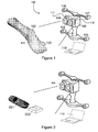
- Figure 1 shows apparatus 100 for capturing a 3D image of an object 101.
- the apparatus 100 includes an imaging device 104 comprising two cameras 111, 112 and four directional light sources 106-109 rigidly affixed to the cameras 111, 112.
- the device 104 is being used to capture part of the surface of a human limb, although it will be appreciated that its application is not limited to the human body, and the device could be used for any object having largely similar characteristics, or sections of larger objects, or surfaces from environments such as walls and floors.
- One or more localisation templates 102, 103 are placed on or near the object 101 so as to be viewable by the imaging device 104 simultaneously with the surface of the object 101.
- Such templates 102, 103 are required to be in the viewing field of the cameras 111, 112 for reconstruction to be performed. Although only a single template 102, 103 is required to reconstruct the image, the surface area of the object 101 that can be acquired when only a single template is used is limited. Increasing the number of templates allows the system to cover as large an area as required. Any suitable method of affixing the templates may be used, such as, for example, attachment using a 'use once' sticky pad, or double-sided tape.
- the viewing device 104 is hand-held, and includes associated casing and handles 105, although it will be noted that this physical configuration is not prescriptive and the device could have any suitable shape and could be supported, for example by a tripod, rather than hand-held. Because the light sources are rigidly affixed relative to the cameras, the positions of the light sources relative to the camera are known.
- An optional feature of the system is a radio transceiver contained within the casing 105 for communicating with and uniquely identifying RFID tags embedded in the associated localisation templates 102, 103.
- a further optional feature of the system is interface hardware for communication with and uniquely identifying embedded EEPROM or similar devices in the associated localisation templates.
- the directional light sources 106-109 are operated simultaneously with both cameras 111, 112, so that each camera obtains a series of 2D images of the object 101 and template(s) 102, 103.
- the 2D images from the cameras are then processed by a processing means to generate a 3D representation of the object 101, as discussed in more detail below.
- the processing means is depicted in this example as a laptop computer 110, although it will be appreciated that processing might also be carried out via an 'on-board' processor. It will be noted that that processing may be carried out either ⁇ on-line' (i.e. during or immediately after image capture), or ⁇ off-line', in which case a series of images are saved, for example to flash memory, and processed later.
- Figure 2 shows a similar hand-held embodiment of the invention in use to image a region of the surface of an inanimate object, in this case a mobile telephone 201.
- a single localisation template 202 need be used, placed near the object, to be viewed simultaneously with the object by the imaging device 104.
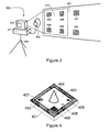
- an alternative apparatus 300 is used to capture 3D images of an extended environment such as an area of wall 301.
- a single light source 302 (such as a hand-held photographic flash) is movable independently of a camera 303, mounted on a tripod 304.
- a series of images is captured by the camera 303, with the light source 302 in a different location for each image.
- An array of templates 305-310 is placed on the wall 301, spaced apart.
- Each template includes a 'light localisation' feature 404, as shown in Figure 4 and discussed in more detail below.
- the light localisation feature 404 on each template is used to resolve the position of the directional light source in each image via image processing on the images of the templates.
- the image processing may be carried out by a dedicated processing device 311, although it will be appreciated that any suitable processing means may be used.
- the series of images taken by the camera 303 are processed in order to acquire 3D information and material surface properties.
- the sampling resolution of the resulting data is directly related to the resolution of the camera 303.
- the camera 303 itself can also be moved between images, so as to image the whole wall in sections (discussed in more detail below). It will be appreciated that a similar approach may also be employed by the imaging device 104 of Figures 1 and 2 to map the surface of an object 101 in sections. There are several reasons why it may be necessary to image objects such as 101,201,301 in sections:
- Figures 3 , 7 , 8 and 9 illustrate the principle of obtaining the image of an extended region of the surface the object 101, 301 in sections. It can be seen in Figure 3 that the viewing area 312 of the camera 303 contains only a subset of the complete wall 301, and four templates 305, 306, 308 and 309 from the full set of six templates 305-310. By obtaining images of multiple sections of wall, a 3D map of the whole surface can be built up. This is further illustrated in figures 8 and 9 .
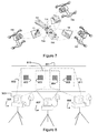
- Figure 7 illustrates the imaging device 104 of Figure 1 in three different positions 705, 706, 707, in each of which the cameras 111, 112 have a different field of view 708, 709, 710.
- Each field of view contains a subset of the total surface area of the object 701 to be imaged, and also contains at least two of the localisation templates 702, 703, 704.
- the key to automated combination of views into a coherent single model is the use of multiple localisation templates, and this is discussed in more detail below.
- the first is photometric reconstruction, in which surface orientation is calculated from the observed variation in reflected energy against the known angle of incidence of the directional source. This provides a relatively high-resolution surface normal map alongside a map of relative surface reflectance (or illumination-free colour), which may be integrated to provide depth, or range, information which specifies the 3D shape of the object surface. Inherent to this method of acquisition is output of good high-frequency detail, but there is also the introduction of low-frequency drift, or curvature, rather than absolute metric geometry because of the nature of the noise present in the imaging process.
- the second method of acquisition is passive stereoscopic reconstruction, which calculates surface depth based on optical triangulation.
- An optional feature of the presently disclosed system is the application of optical filtering to the imaging device and directional sources.
- the goal is to reduce the visibility of specular reflection of the directional sources in the acquired images, which can lead to artefacts in the images which may confuse the reconstruction software. This may be achieved, for example, by the use of an appropriately orientated set of circular polarizer filters.
- Optical filtering has particular benefits when used with the imaging processing carried out by the two methods of 3D reconstruction employed by the presently disclosed system.
- Figure 4 shows an exemplary localisation template (suitable for use as the localisation templates 102, 103, 202, 305-310, 702-4 in Figures 1-3 or 7 ) in detail.
- a reader skilled in the art will understand that various template configurations, both 2D and 3D in nature could be used to perform localisation of the imaging device and directional energy sources, and that many of the features described below are optional or replaceable by functional equivalents.
- the template is a flat planar block 401 with a printed pattern of known metric dimensions and accuracy, consisting of:
- imaging device 104 using light as the directional energy source and a stereo camera pair as an imaging device, will now be described in terms of the functions performed, namely template localisation (with optional identification), photometric 3D reconstruction, passive stereoscopic 3D reconstruction, and 3D reconstruction via integration of photometric and stereoscopic data.
- template localisation with optional identification
- photometric 3D reconstruction passive stereoscopic 3D reconstruction
- 3D reconstruction via integration of photometric and stereoscopic data.
- the combination of multiple viewpoints into a single continuous 3D reconstruction is also described.
- the first function of the system is to localise the imaging device 104 with respect to the one or more templates visible from each viewpoint from which the object is imaged and, in the case where multiple viewpoints are to be used, the relative position of all of the templates themselves.
- the initial field of view of the stereo cameras 111, 112 includes a section of the surface and two localisation templates 102, 103.
- Optical camera localisation is the determination of the pose of the stereo camera system in space (specifically camera roll, tilt and yaw angles along with effective camera centre coordinates X,Y,Z in metric units such as millimetres) with respect to an absolute coordinate frame defined on a localisation template.
- the relative position of the stereo cameras can be determined metrically given certain imaging properties of the cameras such as, for example, focal lengths and the projective relationship between the two cameras, as defined, for example, in the Essential Matrix ( R, I. Hartley and A. Zisserman “Multiple View Geometry in Computer Vision”. Cambridge University Press, ISBN: 0521623049 2000 ).
- Geometric calibration of both an individual camera and a stereo or multi-view camera system is a known technique and can be performed in an image based approach by imaging a calibration template, extracting certain features and using projective geometry to determine parameters specifying the imaging properties of the stereo camera system.
- An implementation of such a technique is described by J-Y Bouguet "Camera Calibration Toolbox for Matlab” http://www.vision.caltech.edu/bougueti/calib doc/index.html .
- optical camera localisation may then be carried out from a single view ( i.e . using a single image from a stereo pair) of a localisation template.
- certain features such as the thin white line 402 in the example template
- projective geometry to compute a homography between the coordinate frame of the template to the camera.
- stereo views of the template given a calibrated stereo system additional accuracy of pose estimation can be obtained and / or the calibration parameters verified.
- Multiple views of the templates can also, in principle, be used to generate key physical parameters needed to describe (or calibrate) the camera, thus potentially allowing the same metric standard to define camera position and the parameters needed for accurate reconstruction.
- the system employs one or more localisation templates positioned on or near the surface of the object to be inspected.
- the viewpoint of the cameras 111, 112 allows them to image templates 102, 103, and where multiple templates are visible then the pose of the stereo cameras 111, 112 can therefore be determined with respect to each of the templates 102, 103 in view.
- a canonical pose can be (arbitrarily) chosen as that computed from an individual template, or as a transformation of any or all of these coordinate frames.
- a canonical view is a single coordinate frame into which all views of the current group of templates are projected.
- the transformations mapping between the relative coordinate frames of templates 102, 103 can be computed trivially as they are imaged simultaneously from the same viewpoint.
- the use of multiple templates, and the computation of the relative pose between the templates is key to imaging a large surface in sections.
- Figure 7 illustrates the system of Figure 1 in use capturing an extensive surface area, again in this example the upper part of a human foot 701.
- Three localisation templates 702, 703, 704 are affixed to the foot 701, and the foot viewed by positioning the imaging device 104 and associated hardware in three positions 705, 706, 707.
- Each field of view 708, 709, 710 overlaps with at least one other field of view and contains at least two out of three templates 702, 703, 704.
- Calibration of the stereo camera system remains constant, and as the relative pose between each template in each view can be computed ( i.e . mapping template 702 to 703, 703 to 704 and 702 to 704), a complete mapping determining the relative pose of all templates along with relative pose for the different positions 705, 706, 707 can be determined.
- each template provides independent localisation from a single viewpoint, there is no need to combine position estimates across viewpoints, avoiding accumulated errors in pose estimation arising from image registration (known as 'drift') leaving only the stacked errors associated with the transformation between canonical view coordinates.
- 'drift' image registration
- a separate image can be taken of the full ensemble of templates to define a single global coordinate system should the error stacking between canonical views be deemed to be unacceptable. This is a significant benefit of the present system over video camera based 'tracking' methods.
- each localisation template 401 includes a coding such as a bar code 406 which is used to uniquely identify that localisation template. Every template is thus unique as long as the coding can be reliably detected. This may not be necessary if:
- the relative pose between pairs of localisation templates can then be used to identify them uniquely. Again, depending on the irregularity of placement and the accuracy of pose estimation it may or may not be necessary to use an orientation marker 405 (as shown in Figure 4 ) to remove the 90° symmetry from the templates.
- Unique identification of templates are not limited to the case where multiple templates are used to image a large surface in sections.
- Unique identification can provide additional metadata on images captured by the system to assist in the processing or storage of the resulting image files.
- One particular example is in the context of medical imaging, in which a codification of the target can be used to assist storing the unique scan with electronic patient records.
- a unique identifier would also assist clinical trials by providing a data audit trail. If the target is to be placed directly on the patient skin then it must not be reused on another patient because of the possibility of cross-infection.
- a non-volatile list of template identifier codes could be stored in the imaging device and used to prevent processing on re-used templates, encouraging sanitary practice.
- the imaging method presently disclosed could be applied to verify build accuracy of components with the codification of the target providing an end-to-end audit trial for QA management.
- the unique identifier could provide a 'watermark' to determine the originator of a 3D image.
- the second function of the system is to perform photometric recovery of the surface of the object under inspection.
- the underlying principle for photometric recovery is that of photometric stereo (PS).
- PS photometric stereo
- a series of photometric images of the surface are acquired, with the camera remaining static with respect to the object's surface but with geometric variation in lighting direction between images.
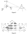
- Figure 5 illustrates such a system. It is desired to capture geometrical information from the surface of an object 501. To achieve this it is imaged by a single camera viewpoint 502 whilst illuminated individually by a number of identical light sources 503 - 505; typically a minimum of three light sources will be used.
- Photometric stereo requires an approximating model of the surface material reflectivity properties. In the general case this may be modelled (at a single point on the surface) by the Bidirectional Reflectance Distribution Function (BRDF).
- BRDF Bidirectional Reflectance Distribution Function
- a simplified model is typically used in order to render the problem tractable.
- variation in P across the surface of the object will be determined in a prior calibration step, and hence can be compensated.
- L will also typically be determined by calibration.
- both calibration steps can be carried out using information obtained by imaging the templates.
- the camera and object remain static, and hence the area of the surface observed by the camera at a specific pixel remains the same. Therefore, the intensities observed at a particular camera pixel across a set of images with varying lighting direction may be considered a set of photometric samples.
- PS can be used to obtain object geometry as a surface normal map and material properties (for example the possibly inhomogeneous Lambertian reflectivity coefficients p).
- PS is not limited to recovery of just simple Lambertian reflectivity; application of more sophisticated models allows colour reflectivity and a measure of, for example, specular reflection to be recovered.
- An alternative (or additional) approach is to provide appropriate optical filtering of the imaging device and light source so as to reduce the visibility of specular reflection in the images.
- the localisation templates can provide a manner in which light direction may be determined from a single image. This can be achieved by computing the relative pose of the localisation template, then (in the case of the light localisation feature 404 being a cone) observing the triangular shadow cast by the cone onto the plane 403 of the template. The direction of the incoming light can be found as the ray cast from the apex of the triangular shadow (which lies on the plane of the template) through the tip of the cone 404, which has known dimensions and hence known location with respect to the coordinate frame of the template. In the case of a matt pyramid then, as the surface normal direction of the four sides of the pyramid are known, the relative intensities of the sides may be used in a manner analogous to Eqn 2 to compute a ray towards the light source.
- Variation in the incoming light intensity ( P ) can be estimated by sampling from, in the case of a cone light localisation feature, the non-shadowed parts of the localisation template.
- a flat area surrounding the pyramid on the localisation template can be used for the same purpose.
- These regions 403 are uniformly white and flat, therefore any variation in lighting intensity across this region will appear as a change in pixel intensity in the camera image.
- Samples may be combined from several localisation templates present in the image and, given that a well diffused light source is used, variation in P will be smooth. Assuming that the templates are distributed across the image then the samples collectively can be considered representative of variation in P across the viewable region of the surface.
- a 2D interpolating function e.g. a bi-quadratic
- a further optional function of the localisation templates is to assist calibration and / or correction for variation in colour response in the imaging system, e.g . camera 'white balance'. This may be achieved through processing the images of the templates as the template is of known reflectivity, having e.g . white and black regions. Methods to achieve this will be well known to those skilled in the art. This function might further be facilitated by incorporation of a specific colour calibration feature 407 in the template, which has coloured regions of known reflectance. This would allow a direct comparison between imaged colour response and known base reflectivity.
- the third function of the system is to perform passive stereoscopic reconstruction using optical triangulation. Note that this technique does not provide for the acquisition of material reflectance properties per se , and is likely (given the same imaging device is used) to produce lower resolution geometrical data than the photometric approach; the benefit is in the noise characteristics of the recovered data, which are complementary to the photometric reconstruction.
- the imaging device is considered to acquire images of the surface of the object from two slightly separated viewpoints, i.e . a stereo image pair.
- depth information can be resolved by correlating 2D points between the images forming the stereo pair. Reconstruction of range information using stereo viewpoints is described, for example, in R, I. Hartley and A. Zisserman Multiple View Geometry in Computer Vision, Cambridge University Press, ISBN: 0521623049 2000 , and illustrated with reference to Figure 6 .
- a plane 601 intersects two points 602, 603 representing the centres of the separated camera viewpoints, two planes 605, 606 representing the camera image planes, and a third point 604 on the surface of the object.
- the images 607, 608 in the conceptual camera image planes of the object surface point 604 are the intersections of rays 609, 610 from the camera centres to the object surface point 604. Therefore, for a given point 607 the corresponding point 608 must lie upon a line which is the intersection of the plane 601 in the other camera image plane 606. Reconstruction of depth information can therefore be achieved given a calibrated stereo camera pair if a relatively dense set of correspondences between stereo views can be achieved.
- There are numerous algorithms in this field for example as described by Kolmogorov and Zabih, "Multi-Camera Scene Reconstruction via Graph Cuts In Proceedings", International Conference on Computer Vision 2003 .
- a benefit of the system described herein is that multiple stereo image pairs can be acquired, with varying directional lighting. This very much increases the likelihood that the surface will have been properly illuminated in at least one of the image pairs at all visible points, and therefore can be reconstructed without missing data. Geometry reconstructed from different stereo images sets can easily be merged to a single unified dataset as the localisation template provides a frame of reference.
- a further issue with passive stereoscopic reconstruction is the presence of direct specular reflections from the dominant light source in the images. Specular reflections often result in areas of high image contrast, with the location on the surface varying with viewing direction. Thus they are known to provide a source of 'false correspondences", hampering stereoscopic reconstruction.
- An approach to minimise this issue is to apply appropriate optical filtering to the imaging device and light sources to minimise visible specular reflections.
- the fourth function of the system is to reconstruct a 3D model of the surface under inspection, along with associated (spatially varying) material properties. This is done by fusing the data reconstructed from the photometric and geometric recovery methods disclosed above.
- Photometric stereo provides recovery of a dense surface normal map alongside coefficients of a (inhomogeneous) material reflectance model.
- the underlying model of surface geometry used will be that of the surface of the object visible to the camera being modelled as a 'range map', i.e. a 2D matrix of range samples.
- the data produced by the geometric reconstruction can be considered an unbiased but relatively low-resolution sampling of the true 'range map', with a predictable quantity of high frequency noise.
- the normal map data provided by the photometric reconstruction can be considered a comparatively high-resolution, but biased, sampling of the derivative of the true 'range map'.
- the reader skilled in the art will appreciate that other representations could be used without departing from the scope of the invention.
- the Surface Operator for example, could be used to fit the normal data to obtain detailed measures of curvature, and the surface represented locally as a manifold via , for example, its geodesics or principle curvatures.
- Photometric recovery offers very high detail geometry, but is subject to low frequency noise (i.e . bias) in recovery.
- Geometric methods are typically lower resolution but have high frequency noise with zero bias. The combination of both approaches is therefore powerful as it offers a high resolution, metric recovery with less imaging hardware and faster processing times.
- the photometric-stereoscopic fusion task is to combine data from the two modalities to produce a single model.
- Wiener filter Several approaches will be known to those skilled in the art, however one particular apposite method is to use a Wiener filter.
- a Wiener filter is the steady-state solution for the optimal state estimation problem as solved using a Kalman filter.
- a Wiener filter is of particular value when there are measurements of a derivative of a signal, such as in the case of the combination of photometric and stereoscopic data.
- the Wiener filter is the result of finding the minimum variance estimate of the steady state reconstructed height.
- the Wiener filter is obtained by finding the Fourier transforms of the measurement signals and assuming that these signals were generated by white noise processes and are corrupted by measurement noise of known frequency spectrum, as explained by S. Smith "Digital Signal Processing: A Practical Guide for Engineers and Engineers", Butterworth-Heinemann 2002 . In this embodiment we assume that, by way of example, the noise processes are themselves white.
- the Wiener filter minimises E ⁇ ⁇ ⁇ z ⁇ - z 2 ⁇ dxdy ⁇ where E[] denotes the expected value.
- ⁇ specifies an overall relative weighting on the data acquired from passive stereoscopic reconstruction. Increasing value restricts the output to be closer to the stereoscopic data. In practice this may be achieved very quickly in the frequency domain by use of standard techniques such as the Fast Fourier Transform. Note that the use of the FFT here is to achieve speed rather than solving a least-squares problem, as in the Wiener filter. Other techniques may also be employed, for example using the Fast Wavelet Transform.
- the output from this stage given the aforementioned geometrical representation of the objects surface as a 'range map' is a fused range map providing a 2D matrix of distances to the surface of the object relative to an arbitrary coordinate frame defined by one or more localisation templates, this range map having improved error characteristics over and above either the photometric or stereoscopic data, alongside a corresponding 2D matrix of material reflectivity coefficients indicating, for example, colour reflectivity.
- a final optional function of the system is to provide an automated method in which data sets from multiple viewpoints may be automatically combined (or 'stitched') into a single coherent data set, to perform 3D imaging of an extended surface of an object. Fusion of geometric data sets may be achieved quite readily if the relative pose between viewpoints can be computed. Fusion of material, i.e. colour reflectance data requires production of illumination invariant material reflectivity maps. Both these tasks are greatly facilitated through the use of multiple localisation templates, as presently disclosed.
- Figure 7 shows an exemplary scanning configuration to achieve this, based on the hardware configuration shown in Figure 1 and using overlapping viewpoints 708, 709, 710.
- Carrying out the imaging and processing steps above produces three data sets 711, 712, 713, each representing a sub-section of the surface of the object 701.
- Each viewpoint shares at least one template in common with another, allowing the change in camera pose relative to the commonly viewed template to be determined.
- a set of transformations mapping any one camera view to the others can thus be determined with respect to an arbitrarily chosen coordinate frame.
- the sections of the geometry may be registered with respect to each other and then standard algorithms used to fuse the data set, as described for example by J. C. Carr and R. K. Beatson and J.B. Cherrie and T. J. Mitchell and W. R. Fright and B. C. McCallum and T. R. Evans "Reconstruction and Representation of 3D Objects with Radial Basis Functions" in Proceedings of ACM SIGGRAPH pages 67-76, 2001 .
- the key to stitching material reflectance data sets acquired from multiple viewpoints is to ensure overall illumination and colour constancy.
- the overall distance of the light sources will not be constant which, if a template system is not used, can lead to variation in, for example, global illumination in material properties.
- the use of a set of calibrated templates, to provide a reflectance standard for photometric images renders such techniques unnecessary. This is because all reconstruction is carried out with respect to calibrated templates, so variation in incident lighting intensity, camera colour balance etc .
- Figure 8 illustrates the system of Figure 3 in use capturing an extensive surface area, again in this example a wall 801.
- Four localisation templates 802-805 (similar to the localisation template 401 shown in Figure 4 ) are affixed to the wall, and the wall viewed by positioning the imaging device 303 and associated hardware 311 in three positions 806, 807, 808).
- Overlapping fields of view 809, 810, 811 each contain at least two out of four templates.
- Camera calibration remains constant, and as the relative pose between each template in each view can be computed (i.e. mapping 802 to 803, 803 to 804 and 804 to 805), a complete mapping determining the relative pose of all templates along with relative pose for positions 806, 807, 808 can be determined in a similar manner to the arrangement of Figure 7 .
- such a device may be coupled to the main imaging device 303.
- Various approaches could be used, for example laser striping or speckling (as described in WO 2007/129047 ), white light or fringe based projection. Note that these systems do not provide a method for acquiring material reflectance properties per se and, as with the passive stereoscopic approach, are likely to produce lower resolution geometrical data that the photometric approach.
- a complete set of relative pose transformations for all templates can be computed.
- Knowledge of pose of the localization templates itself offers a further method of providing approximate overall geometry for the surface under inspection. Given that the underlying surface is smoothly curving at the gross scale of the localization templates, then the templates (appropriately placed) can be considered as approximating the local surface tangent.
- Each template thus provides a single absolute location (vertex) in space on the surface under inspection and a measure of the instantaneous local surface normal at this point, found as the normal to the plane of the template.
- a global coordinate frame can be arbitrarily chosen and a 3D surface fit to the vertex and normal data.
- a coarse model of the underlying 3D structure may be derived without use of additional geometric scanning hardware.
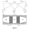
- Figure 9 illustrates one exemplary method which can be used in the merging of reconstructed photometric and geometric data.
- Figure 9 is a schematic representation of a 'birds eye' view of three camera viewpoints 901, 902 903, each viewpoint having a corresponding image plane 904, 905, 906.
- the images themselves may consist of, for example, photometric normal data or geometric range data.
- the result is a reconstructed viewpoint 907 - the trapezoidal areas 908 and 910 result from the planar projection of the outer viewpoints 904, 506, with the rectangular area 909 being the original image 905.
- the localisation template in Figure 4 illustrates a particular set of geometric features, but it will be appreciated that any suitable features usable to establish a metrology may be used.
- the exemplary imaging devices have been described as comprising "cameras” but any suitable image sensors may be used. Indeed, a single sensor with a lens splitter may also be suitable. Other possible examples include video cameras, CMOS sensors etc.
- the illuminating radiation need not be visible light; any suitable form of energy may be used, and the image sensors will be chosen accordingly.
- the cameras have been described in various embodiments as being “rigidly” affixed to the casing but it will be appreciated that this includes situations such as cameras telescopically mounted to the casing.
Landscapes
- Engineering & Computer Science (AREA)
- Computer Vision & Pattern Recognition (AREA)
- Physics & Mathematics (AREA)
- General Physics & Mathematics (AREA)
- Theoretical Computer Science (AREA)
- Length Measuring Devices By Optical Means (AREA)
- Apparatus For Radiation Diagnosis (AREA)
- Measurement Of Optical Distance (AREA)
Claims (15)
- Vorrichtung zum Berechnen eines dreidimensionalen Modells eines Objekts (101, 201), umfassend:ein tragbares, handgeführtes Instrument, das mehrere Quellen gerichteter Energie (106-109), die dafür eingerichtet sind, das Objekt gerichtet zu beleuchten, und eine Bilderfassungsbaugruppe (104) mit mindestens zwei räumlich getrennten Betrachterstandpunkten (111, 112) an in Bezug aufeinander feststehenden Positionen aufweist, wobei die Bilderfassungsbaugruppe dafür eingerichtet ist, eine Folge von Bildern des Objekts an jedem Betrachterstandpunkt aufzunehmen, wenn das Objekt durch jede der Quellen beleuchtet wird;mindestens eine Lokalisierungsschablone (102, 103, 202; 401) mit vorbestimmten geometrischen Merkmalen (402-408), wobei die Lokalisierungsschablone in Gebrauch so angeordnet wird, dass sie für mindestens einen der Betrachterstandpunkte gleichzeitig mit dem Objekt sichtbar ist; undeinen Prozessor (110), der dafür eingerichtet ist, die an den Betrachterstandpunkten aufgenommenen Bilder zu analysieren, um dadurch:den Standort und die Stellung jedes Betrachterstandpunkts in Bezug auf die Schablone für jedes Bild in der Folge von Bildern zu bestimmen;photometrische Daten für das Objekt unter Verwendung des bzw. der berechneten Standorts bzw. Stellung der Betrachterstandpunkte und der Richtung der Beleuchtung von jeder Energiequelle zu erzeugen;geometrische Daten für das Objekt zu erzeugen, die ein dreidimensionales Skelettmodell des Objekts umfassen, und zwar durch Durchführen einer stereoskopischen Rekonstruktion unter Verwendung optischer Triangulation, um dadurch die grobe äußere Form des Objekts bereitzustellen; unddie geometrischen Daten und photometrischen Daten zu kombinieren, indem die photometrischen Daten verwendet werden, um hochfrequente geometrische Einzelheiten auf der groben äußeren Form bereitzustellen, um dadurch das dreidimensionale Modell zu konstruieren.
- Vorrichtung nach Anspruch 1, wobei sich die mehreren Energiequellen (106-109) an feststehenden Positionen in Bezug auf die Betrachterstandpunkte (111, 112) befinden, so dass die Richtung der Beleuchtung von jeder der Quellen in Bezug auf die Betrachterstandpunkte bekannt ist.
- Vorrichtung nach Anspruch 1, wobei:die Lokalisierungsschablone (102, 103) in Gebrauch so angeordnet wird, dass sie durch die Quellen (106-109) beleuchtet wird, wenn sie für mindestens einen der Betrachterstandpunkte (111, 112) gleichzeitig mit dem Objekt (101, 201) sichtbar ist;der Prozessor (110) dafür eingerichtet ist, die Richtung der Beleuchtung aus den Teilen jedes Bildes zu berechnen, das die Schablone einschließt;und die Schablonen wahlweise zwischen Bildern in der Folge von Bildern bewegbar in Bezug auf die Betrachterstandpunkte sind.
- Vorrichtung nach Anspruch 3, wobei die Schablone (401) ein dreidimensionales Quellenlokalisierungsmerkmal (404) aufweist, das wahlweise eine Pyramide oder einen Kegel mit bekannten Abmessungen umfasst, und wobei der Prozessor (110) dafür eingerichtet ist, die Stellung der Quelle in Bezug auf die Schablone aus den Teilen derjenigen Bilder zu bestimmen, die das Quellenlokalisierungsmerkmal einschließen.
- Vorrichtung nach einem der vorhergehenden Ansprüche, umfassend eine Vielzahl von Lokalisierungsschablonen (702, 703, 704), wobei die Vorrichtung so angeordnet ist, dass:die Betrachterstandpunkte (111, 112) und Quellen (106-109) an einem ersten Standort positioniert werden können, an dem mindestens zwei erste Schablonen gleichzeitig mit einem ersten Abschnitt des Objekts für mindestens einen der Betrachterstandpunkte sichtbar sind; unddie Betrachterstandpunkte und Quellen zu einem zweiten Standort bewegbar sind, an dem mindestens eine der mindestens zwei ersten Schablonen gleichzeitig mit mindestens einer anderen Schablone und einem zweiten Abschnitt des Objekts, der sich mit dem ersten Abschnitt überschneidet, weiterhin für mindestens einen der Betrachterstandpunkte sichtbar sind;wobei die Betrachterstandpunkte dafür eingerichtet sind, Bilder von den ersten und zweiten Standorten aufzunehmen, und wobei der Prozessor dafür eingerichtet ist, Daten aus den Bildern zu kombinieren, um dadurch ein Modell zu erzeugen, das die ersten und zweiten Abschnitte des Objekts abdeckt.
- Vorrichtung nach einem der vorhergehenden Ansprüche, wobei ein optischer Sensor an jedem Betrachterstandpunkt angeordnet ist.
- Vorrichtung nach einem der vorhergehenden Ansprüche, wobei die Vorrichtung optische Filterung zum Verringern der Sichtbarkeit direkter Reflexionen der Quelle in den Bildern aufweist.
- Vorrichtung nach einem der vorhergehenden Ansprüche, wobei die oder jede Schablone (702-704) ein eindeutiges Identifizierungsmerkmal aufweist, das ermöglicht, die oder jede Schablone von anderen Schablonen zu unterscheiden, wobei das eindeutige Identifizierungsmerkmal wahlweise einen Strichcode, der durch den Prozessor decodierbar ist, ein RFID-Etikett oder einen EEPROM-Chip umfasst.
- Vorrichtung nach einem der vorhergehenden Ansprüche, wobei das Objekt (101, 201) mindestens einen Teil eines dreidimensionalen Gegenstandes umfasst und/oder das Objekt eine Oberfläche oder einen Teil einer Oberfläche umfasst.
- Verfahren zum Berechnen eines dreidimensionalen Modells eines Objekts (101, 201), umfassend:gerichtetes Beleuchten des Objekts mit mehreren Quellen gerichteter Energie (106-109), die in einem tragbaren, handgeführten Instrument untergebracht sind;Aufnehmen einer Folge von Bildern des durch jede der Quellen beleuchteten Objekts an jedem von mindestens zwei räumlich getrennten Betrachterstandpunkten (111, 112), die sich an in Bezug aufeinander feststehenden Positionen befinden und in dem Instrument untergebracht sind, wobei die Bilder von mindestens einem der Betrachterstandpunkte auch mindestens eine Lokalisierungsschablone (102, 103, 202) mit vorbestimmten geometrischen Merkmalen aufweisen;aus den aufgenommenen Bildern erfolgendes Bestimmen des Standorts und der Stellung jedes Betrachterstandpunkts in Bezug auf die Schablone;aus den aufgenommenen Bildern erfolgendes Erzeugen photometrischer Daten für das Objekt unter Verwendung des bzw. der berechneten Standorts bzw. Stellung der Betrachterstandpunkte und der Richtung der Beleuchtung von jeder Energiequelle;Erzeugen geometrischer Daten, die ein dreidimensionales Skelettmodell des Objekts umfassen, und zwar durch Durchführen einer stereoskopischen Rekonstruktion unter Verwendung optischer Triangulation, um dadurch die grobe äußere Form des Objekts bereitzustellen; undKombinieren der geometrischen Daten und photometrischen Daten, indem die photometrischen Daten verwendet werden, um hochfrequente geometrische Einzelheiten auf der groben äußeren Form bereitzustellen, um dadurch das dreidimensionale Modell zu konstruieren.
- Verfahren nach Anspruch 10, wobei die Schablone (401) ein dreidimensionales Quellenlokalisierungsmerkmal (404) aufweist, wobei das Verfahren ferner umfasst: Bestimmen der Stellung der Quellen (106-109) in Bezug auf die Schablone aus den Teilen derjenigen Bilder, die das Quellenlokalisierungsmerkmal einschließen.
- Verfahren nach Anspruch 10 oder 11, ferner umfassend:Positionieren der Betrachterstandpunkte (111, 112) und Quellen (106-109) an einem ersten Standort, an dem mindestens zwei erste Schablonen (702, 703, 704) gleichzeitig mit einem ersten Abschnitt des Objekts für mindestens einen der Betrachterstandpunkte sichtbar sind;Aufnehmen eines ersten Bildes an jedem Betrachterstandpunkt vom ersten Standort aus, wobei jedes erste Bild den ersten Abschnitt des Objekts und die mindestens zwei ersten Schablonen aufweist;Bewegen der Betrachterstandpunkte und Quellen zu einem zweiten Standort, an dem mindestens eine der mindestens zwei ersten Schablonen gleichzeitig mit mindestens einer anderen Schablone und einem zweiten Abschnitt des Objekts, der sich mit dem ersten Abschnitt überschneidet, weiterhin für mindestens einen der Betrachterstandpunkte sichtbar sind;Aufnehmen eines zweiten Bildes an jedem Betrachterstandpunkt vom zweiten Standort aus; undKombineren von Daten aus den ersten und zweiten Bildern, um dadurch ein Modell zu erzeugen, das die ersten und zweiten Abschnitte des Objekts abdeckt.
- Verfahren nach einem der Ansprüche 10 bis 12, wobei die oder jede Schablone (702-704) aufweist: ein eindeutiges Identifizierungsmerkmal aufweist, das ermöglicht, die oder jede Schablone von anderen Schablonen zu unterscheiden; und wahlweise:das eindeutige Identifizierungsmerkmal einen Strichcode (406) umfasst, wobei das Verfahren ferner umfasst: Identifizieren des Strichcodes in dem Bild und Decodieren des Strichcodes, um die Schablone zu identifizieren; oderdas eindeutige Identifizierungsmerkmal ein RFID-Etikett aufweist, wobei das Verfahren ferner umfasst: Verwenden eines Funkfrequenzlesegeräts, um die Schablone zu identifizieren; oderdas eindeutige Identifizierungsmerkmal einen EEPROM-Chip aufweist, wobei das Verfahren umfasst: Verwenden eines Lesegeräts, um die Schablone zu identifizieren.
- Vorrichtung nach einem der Ansprüche 10 bis 13, wobei das Objekt (101, 201) mindestens einen Teil eines dreidimensionalen Gegenstandes umfasst.
- Vorrichtung nach einem der Ansprüche 10 bis 14, wobei das Objekt (101, 201) eine Oberfläche oder einen Teil einer Oberfläche umfasst.
Applications Claiming Priority (2)
| Application Number | Priority Date | Filing Date | Title |
|---|---|---|---|
| GB0805971.9A GB2458927B (en) | 2008-04-02 | 2008-04-02 | 3D Imaging system |
| PCT/GB2009/050299 WO2009122200A1 (en) | 2008-04-02 | 2009-03-27 | 3d imaging system |
Publications (2)
| Publication Number | Publication Date |
|---|---|
| EP2272047A1 EP2272047A1 (de) | 2011-01-12 |
| EP2272047B1 true EP2272047B1 (de) | 2012-03-14 |
Family
ID=39409930
Family Applications (1)
| Application Number | Title | Priority Date | Filing Date |
|---|---|---|---|
| EP09727607A Active EP2272047B1 (de) | 2008-04-02 | 2009-03-27 | 3d-bildgebungssystem |
Country Status (8)
| Country | Link |
|---|---|
| US (1) | US8773508B2 (de) |
| EP (1) | EP2272047B1 (de) |
| JP (1) | JP5467404B2 (de) |
| AT (1) | ATE549703T1 (de) |
| ES (1) | ES2384086T3 (de) |
| GB (1) | GB2458927B (de) |
| NZ (1) | NZ588740A (de) |
| WO (1) | WO2009122200A1 (de) |
Cited By (1)
| Publication number | Priority date | Publication date | Assignee | Title |
|---|---|---|---|---|
| US11850025B2 (en) | 2011-11-28 | 2023-12-26 | Aranz Healthcare Limited | Handheld skin measuring or monitoring device |
Families Citing this family (69)
| Publication number | Priority date | Publication date | Assignee | Title |
|---|---|---|---|---|
| US10469831B2 (en) * | 2002-06-07 | 2019-11-05 | University Of Southern California | Near-instant capture of high-resolution facial geometry and reflectance |
| US10368771B2 (en) | 2008-03-13 | 2019-08-06 | Alexander Svojanovsky | EEG electrode and multi-channel EEG electrode system |
| US20110066020A1 (en) * | 2008-03-13 | 2011-03-17 | Alexander Svojanovsky | Multi-channel eeg electrode system |
| WO2011014419A1 (en) | 2009-07-31 | 2011-02-03 | 3Dmedia Corporation | Methods, systems, and computer-readable storage media for creating three-dimensional (3d) images of a scene |
| US9380292B2 (en) | 2009-07-31 | 2016-06-28 | 3Dmedia Corporation | Methods, systems, and computer-readable storage media for generating three-dimensional (3D) images of a scene |
| US8436893B2 (en) | 2009-07-31 | 2013-05-07 | 3Dmedia Corporation | Methods, systems, and computer-readable storage media for selecting image capture positions to generate three-dimensional (3D) images |
| JP5615055B2 (ja) * | 2010-06-18 | 2014-10-29 | キヤノン株式会社 | 情報処理装置及びその処理方法 |
| US9013550B2 (en) * | 2010-09-09 | 2015-04-21 | Qualcomm Incorporated | Online reference generation and tracking for multi-user augmented reality |
| US9185388B2 (en) | 2010-11-03 | 2015-11-10 | 3Dmedia Corporation | Methods, systems, and computer program products for creating three-dimensional video sequences |
| US8274552B2 (en) | 2010-12-27 | 2012-09-25 | 3Dmedia Corporation | Primary and auxiliary image capture devices for image processing and related methods |
| WO2012092246A2 (en) | 2010-12-27 | 2012-07-05 | 3Dmedia Corporation | Methods, systems, and computer-readable storage media for identifying a rough depth map in a scene and for determining a stereo-base distance for three-dimensional (3d) content creation |
| US10200671B2 (en) | 2010-12-27 | 2019-02-05 | 3Dmedia Corporation | Primary and auxiliary image capture devices for image processing and related methods |
| ITFI20110045A1 (it) * | 2011-03-26 | 2012-09-27 | Menci Software S R L | Apparato e metodo per la rilevazione e la ricostruzione di immagini in tre dimensioni. |
| US9292963B2 (en) * | 2011-09-28 | 2016-03-22 | Qualcomm Incorporated | Three-dimensional object model determination using a beacon |
| JP2013096784A (ja) * | 2011-10-31 | 2013-05-20 | Toppan Printing Co Ltd | 表面特性測定装置及びコンピュータプログラム |
| WO2013071416A1 (en) | 2011-11-17 | 2013-05-23 | Techmed 3D Inc. | Method and system for forming a virtual model of a human subject |
| US9055289B2 (en) * | 2011-11-23 | 2015-06-09 | Korea Institute Of Science And Technology | 3D display system |
| FR2991448B1 (fr) * | 2012-06-01 | 2015-01-09 | Centre Nat Rech Scient | Procede de mesures tridimensionnelles par stereo-correlation utilisant une representation parametrique de l'objet mesure |
| US9286530B2 (en) | 2012-07-17 | 2016-03-15 | Cognex Corporation | Handheld apparatus for quantifying component features |
| US9291527B2 (en) * | 2012-07-25 | 2016-03-22 | TIREAUDIT.COM, Inc. | System and method for analysis of surface features |
| KR101385601B1 (ko) | 2012-09-17 | 2014-04-21 | 한국과학기술연구원 | 손동작 인식 및 인터렉션을 위한 장갑장치 및 방법 |
| GB201219171D0 (en) * | 2012-10-25 | 2012-12-12 | Epipole Ltd | Image acquisition apparatus |
| US9857470B2 (en) * | 2012-12-28 | 2018-01-02 | Microsoft Technology Licensing, Llc | Using photometric stereo for 3D environment modeling |
| US9416479B2 (en) | 2013-06-03 | 2016-08-16 | Whirlpool Corporation | Methods of determining a load size in a laundry treating appliance |
| US9382654B2 (en) | 2013-06-03 | 2016-07-05 | Whirlpool Corporation | Method of determining a load size in a laundry treating appliance |
| ITBO20130407A1 (it) * | 2013-07-26 | 2015-01-27 | Swisslog Italia Spa | Dispositivo e procedimento per singolarizzare prodotti raggruppati in blister |
| WO2015030623A1 (en) * | 2013-09-02 | 2015-03-05 | 3Divi Company | Methods and systems for locating substantially planar surfaces of 3d scene |
| WO2015077455A1 (en) | 2013-11-25 | 2015-05-28 | Digimarc Corporation | Methods and systems for contextually processing imagery |
| US9958383B2 (en) * | 2014-12-18 | 2018-05-01 | Microsoft Technology Licensing, Llc. | Range camera |
| WO2016103285A1 (en) * | 2014-12-24 | 2016-06-30 | Datalogic Ip Tech S.R.L. | System and method for reading direct part marking (dpm) codes on objects |
| US10198872B2 (en) | 2015-08-10 | 2019-02-05 | The Board Of Trustees Of The Leland Stanford Junior University | 3D reconstruction and registration of endoscopic data |
| JP2018533099A (ja) | 2015-09-24 | 2018-11-08 | カリフォルニア インスティチュート オブ テクノロジー | 三次元ディスプレイを用いたデータ可視化システム及び方法 |
| CN108139202B (zh) * | 2015-09-30 | 2021-06-11 | 索尼公司 | 图像处理装置、图像处理方法和程序 |
| GB2544263A (en) * | 2015-11-03 | 2017-05-17 | Fuel 3D Tech Ltd | Systems and methods for imaging three-dimensional objects |
| GB2544460A (en) * | 2015-11-03 | 2017-05-24 | Fuel 3D Tech Ltd | Systems and methods for generating and using three-dimensional images |
| GB2544725A (en) * | 2015-11-03 | 2017-05-31 | Fuel 3D Tech Ltd | Systems and methods for forming models of a three-dimensional objects |
| US10438036B1 (en) | 2015-11-09 | 2019-10-08 | Cognex Corporation | System and method for reading and decoding ID codes on a curved, sloped and/or annular object |
| GB2545394A (en) * | 2015-11-27 | 2017-06-21 | Fuel 3D Tech Ltd | Systems and methods for forming three-dimensional models of objects |
| CN105627926B (zh) * | 2016-01-22 | 2017-02-08 | 尹兴 | 四像机组平面阵列特征点三维测量系统及测量方法 |
| WO2017130639A1 (ja) * | 2016-01-28 | 2017-08-03 | 株式会社リコー | 画像処理装置、撮像装置、移動体機器制御システム、画像処理方法、及びプログラム |
| US11472234B2 (en) | 2016-03-04 | 2022-10-18 | TIREAUDIT.COM, Inc. | Mesh registration system and method for diagnosing tread wear |
| US10789773B2 (en) | 2016-03-04 | 2020-09-29 | TIREAUDIT.COM, Inc. | Mesh registration system and method for diagnosing tread wear |
| US10013527B2 (en) | 2016-05-02 | 2018-07-03 | Aranz Healthcare Limited | Automatically assessing an anatomical surface feature and securely managing information related to the same |
| US20180091797A1 (en) * | 2016-09-27 | 2018-03-29 | The Boeing Company | Apparatus and method of compensating for relative motion of at least two aircraft-mounted cameras |
| JP7013144B2 (ja) * | 2016-10-12 | 2022-01-31 | キヤノン株式会社 | 画像処理装置、画像処理方法およびプログラム |
| US11116407B2 (en) | 2016-11-17 | 2021-09-14 | Aranz Healthcare Limited | Anatomical surface assessment methods, devices and systems |
| GB2559978A (en) | 2017-02-22 | 2018-08-29 | Fuel 3D Tech Limited | Systems and methods for obtaining eyewear information |
| WO2018160720A1 (en) * | 2017-03-01 | 2018-09-07 | Canfield Scientific, Incorporated | Three dimensional image capture |
| EP4183328A1 (de) | 2017-04-04 | 2023-05-24 | Aranz Healthcare Limited | Anatomische oberflächenbeurteilungsverfahren, vorrichtungen und systeme |
| US10766145B2 (en) * | 2017-04-14 | 2020-09-08 | Brown University | Eye in-hand robot |
| CN107403449B (zh) * | 2017-08-09 | 2023-11-24 | 深度创新科技(深圳)有限公司 | 一种基于光度立体视觉的视觉系统及其三维重建方法 |
| DE102017122627B4 (de) * | 2017-09-28 | 2021-04-01 | Carl Zeiss Industrielle Messtechnik Gmbh | Optisches Messsystem und Messverfahren |
| WO2019079598A1 (en) * | 2017-10-18 | 2019-04-25 | Brown University | PROBABILISTIC PROBABILISTIC OBJECTS-ROBUST AND REPRODUCIBLE PLACEMENT |
| US10819972B2 (en) | 2018-05-03 | 2020-10-27 | Osram Sylvania Inc. | Method and apparatus for light and computer vision based dimensional metrology and 3D reconstruction |
| US10621762B2 (en) | 2018-05-14 | 2020-04-14 | Virtualitics, Inc. | Systems and methods for high dimensional 3D data visualization |
| US10785422B2 (en) | 2018-05-29 | 2020-09-22 | Microsoft Technology Licensing, Llc | Face recognition using depth and multi-spectral camera |
| GB201809768D0 (en) | 2018-06-14 | 2018-08-01 | Fuel 3D Tech Limited | Deformity edge detection |
| CN108898628A (zh) * | 2018-06-21 | 2018-11-27 | 北京纵目安驰智能科技有限公司 | 基于单目的车辆三维目标姿态估计方法、系统、终端和存储介质 |
| US11080877B2 (en) | 2018-08-02 | 2021-08-03 | Matthew B. Schoen | Systems and methods of measuring an object in a scene of a captured image |
| US11245875B2 (en) | 2019-01-15 | 2022-02-08 | Microsoft Technology Licensing, Llc | Monitoring activity with depth and multi-spectral camera |
| US11288842B2 (en) | 2019-02-15 | 2022-03-29 | Interaptix Inc. | Method and system for re-projecting and combining sensor data for visualization |
| JP6905651B1 (ja) * | 2019-12-13 | 2021-07-21 | 川崎重工業株式会社 | ロボットシステム及びワークの3次元モデルの形成方法 |
| CN111161358B (zh) * | 2019-12-31 | 2022-10-21 | 华中科技大学鄂州工业技术研究院 | 一种用于结构光深度测量的相机标定方法和装置 |
| US11715221B2 (en) | 2020-01-02 | 2023-08-01 | Lumio 3D Co., Ltd. | System and method for acquisition of three-dimensional information of body parts |
| CN112465898B (zh) * | 2020-11-20 | 2023-01-03 | 上海交通大学 | 一种基于棋盘格标定板的物体3d位姿标签获取方法 |
| US11745353B2 (en) | 2020-11-30 | 2023-09-05 | Google Llc | Recovering material properties with active illumination and camera on a robot manipulator |
| US11694385B2 (en) * | 2021-06-08 | 2023-07-04 | Sony Group Corporation | 3D microgeometry and reflectance modeling |
| CN114812407B (zh) * | 2022-03-25 | 2024-03-19 | 合肥图迅电子科技有限公司 | 基于光度立体3d重建的芯片锡球三维高度检测方法及系统 |
| CN116128736B (zh) * | 2023-04-19 | 2023-08-15 | 广东三姆森科技股份有限公司 | 一种扫描成像方法、装置、设备及介质 |
Family Cites Families (23)
| Publication number | Priority date | Publication date | Assignee | Title |
|---|---|---|---|---|
| JP3047017B2 (ja) * | 1991-07-31 | 2000-05-29 | 工業技術院長 | 画像処理方法 |
| US6858826B2 (en) * | 1996-10-25 | 2005-02-22 | Waveworx Inc. | Method and apparatus for scanning three-dimensional objects |
| WO2001039124A2 (en) * | 1999-11-23 | 2001-05-31 | Canon Kabushiki Kaisha | Image processing apparatus |
| US6686921B1 (en) * | 2000-08-01 | 2004-02-03 | International Business Machines Corporation | Method and apparatus for acquiring a set of consistent image maps to represent the color of the surface of an object |
| GB2370738B (en) * | 2000-10-27 | 2005-02-16 | Canon Kk | Image processing apparatus |
| US6781618B2 (en) * | 2001-08-06 | 2004-08-24 | Mitsubishi Electric Research Laboratories, Inc. | Hand-held 3D vision system |
| JP2003065736A (ja) * | 2001-08-24 | 2003-03-05 | Sanyo Electric Co Ltd | 3次元モデリング装置 |
| US20030074223A1 (en) | 2001-09-24 | 2003-04-17 | Scott Laboratories, Inc. | Methods and apparatuses for assuring quality and safety of drug administration and medical products and kits |
| US20030215130A1 (en) * | 2002-02-12 | 2003-11-20 | The University Of Tokyo | Method of processing passive optical motion capture data |
| JP4323779B2 (ja) * | 2002-11-21 | 2009-09-02 | 日本電信電話株式会社 | 3次元形状計測方法および3次元形状計測装置 |
| US7084386B2 (en) * | 2003-05-02 | 2006-08-01 | International Business Machines Corporation | System and method for light source calibration |
| JP4200951B2 (ja) * | 2003-08-28 | 2008-12-24 | 株式会社デンソーウェーブ | 非接触型データキャリア、その端末機器およびアクセスシステム |
| JP3967367B2 (ja) | 2004-12-07 | 2007-08-29 | 松下電器産業株式会社 | 画像変換方法、装置およびプログラム、テクスチャマッピング方法、装置およびプログラム、並びに、サーバークライアントシステム |
| JP2006229833A (ja) * | 2005-02-21 | 2006-08-31 | Konica Minolta Photo Imaging Inc | 撮像装置 |
| JP5002144B2 (ja) * | 2005-09-30 | 2012-08-15 | 株式会社トプコン | 三次元計測用投影装置及びシステム |
| US20070091174A1 (en) * | 2005-09-30 | 2007-04-26 | Topcon Corporation | Projection device for three-dimensional measurement, and three-dimensional measurement system |
| JP2007206797A (ja) * | 2006-01-31 | 2007-08-16 | Omron Corp | 画像処理方法および画像処理装置 |
| GB0608841D0 (en) * | 2006-05-04 | 2006-06-14 | Isis Innovation | Scanner system and method for scanning |
| WO2008000055A1 (en) * | 2006-06-30 | 2008-01-03 | Vx Technologies Inc. | Methods for simultaneous multi-set point matching |
| FR2904455B1 (fr) * | 2006-07-27 | 2009-04-17 | Axs Ingenierie | Procede d'imagerie informatise permettant une reconstruction tridimensionnelle a partir d'images radiographiques bidimensionnelles ; dispositif de mise en oeuvre. |
| CN100470590C (zh) * | 2007-02-05 | 2009-03-18 | 武汉大学 | 相机标定方法及所用标定装置 |
| US8105487B2 (en) * | 2007-09-25 | 2012-01-31 | Fresenius Medical Care Holdings, Inc. | Manifolds for use in conducting dialysis |
| US8107721B2 (en) * | 2008-05-29 | 2012-01-31 | Mitsubishi Electric Research Laboratories, Inc. | Method and system for determining poses of semi-specular objects |
-
2008
- 2008-04-02 GB GB0805971.9A patent/GB2458927B/en active Active
-
2009
- 2009-03-27 EP EP09727607A patent/EP2272047B1/de active Active
- 2009-03-27 JP JP2011502433A patent/JP5467404B2/ja not_active Expired - Fee Related
- 2009-03-27 WO PCT/GB2009/050299 patent/WO2009122200A1/en active Application Filing
- 2009-03-27 NZ NZ588740A patent/NZ588740A/xx not_active IP Right Cessation
- 2009-03-27 ES ES09727607T patent/ES2384086T3/es active Active
- 2009-03-27 AT AT09727607T patent/ATE549703T1/de active
- 2009-03-27 US US12/935,046 patent/US8773508B2/en active Active
Cited By (1)
| Publication number | Priority date | Publication date | Assignee | Title |
|---|---|---|---|---|
| US11850025B2 (en) | 2011-11-28 | 2023-12-26 | Aranz Healthcare Limited | Handheld skin measuring or monitoring device |
Also Published As
| Publication number | Publication date |
|---|---|
| WO2009122200A1 (en) | 2009-10-08 |
| US20110102550A1 (en) | 2011-05-05 |
| ES2384086T3 (es) | 2012-06-29 |
| GB2458927B (en) | 2012-11-14 |
| GB2458927A (en) | 2009-10-07 |
| JP2011516849A (ja) | 2011-05-26 |
| NZ588740A (en) | 2012-07-27 |
| JP5467404B2 (ja) | 2014-04-09 |
| EP2272047A1 (de) | 2011-01-12 |
| US8773508B2 (en) | 2014-07-08 |
| ATE549703T1 (de) | 2012-03-15 |
| GB0805971D0 (en) | 2008-05-07 |
Similar Documents
| Publication | Publication Date | Title |
|---|---|---|
| EP2272047B1 (de) | 3d-bildgebungssystem | |
| JP5337243B2 (ja) | 表面特徴の適応型3次元走査システム | |
| CN110672039B (zh) | 一种基于平面反射镜的物体全方位三维测量方法 | |
| Ahmadabadian et al. | A comparison of dense matching algorithms for scaled surface reconstruction using stereo camera rigs | |
| WO2021140886A1 (ja) | 三次元モデル生成方法、情報処理装置およびプログラム | |
| US20160134860A1 (en) | Multiple template improved 3d modeling of imaged objects using camera position and pose to obtain accuracy | |
| US20030066949A1 (en) | Method and apparatus for scanning three-dimensional objects | |
| EP3069100B1 (de) | 3d abbildungssystem | |
| JP2004127239A (ja) | 較正物体を用いて複数のカメラを較正するための方法およびシステム | |
| GB2524983A (en) | Method of estimating imaging device parameters | |
| JP2009512049A (ja) | 画像処理方法および装置 | |
| EP3382645A2 (de) | Verfahren zur erzeugung eines 3d-modells auf basis von structure from motion und photometrischem stereo von sparse 2d bildern | |
| WO2022078442A1 (zh) | 一种基于光扫描和智能视觉融合的3d信息采集方法 | |
| Hafeez et al. | Image based 3D reconstruction of texture-less objects for VR contents | |
| Bergström et al. | Virtual projective shape matching in targetless CAD-based close-range photogrammetry for efficient estimation of specific deviations | |
| JP2005195335A (ja) | 3次元画像撮影装置および方法 | |
| Özdemir et al. | A multi-purpose benchmark for photogrammetric urban 3D reconstruction in a controlled environment | |
| Błaszczak-Bąk et al. | Measurement methodology for surface defects inventory of building wall using smartphone with light detection and ranging sensor | |
| Pavlidis et al. | 3D Digitization of tangible heritage | |
| Hafeez et al. | 3D surface reconstruction of smooth and textureless objects | |
| Petković et al. | A note on geometric calibration of multiple cameras and projectors | |
| Jarron et al. | Automatic detection and labelling of photogrammetric control points in a calibration test field | |
| Ni et al. | 3D reconstruction of small plant from multiple views | |
| Altuntas et al. | The Registration of Laser Scanner Three-dimensional Point Clouds Using Two-dimensional Images Recorded With a Sensor Combination Camera. | |
| Altuntaş et al. | Estimation of exterior parameters of sensor combination for efficient 3d modeling |
Legal Events
| Date | Code | Title | Description |
|---|---|---|---|
| PUAI | Public reference made under article 153(3) epc to a published international application that has entered the european phase |
Free format text: ORIGINAL CODE: 0009012 |
|
| 17P | Request for examination filed |
Effective date: 20101018 |
|
| AK | Designated contracting states |
Kind code of ref document: A1 Designated state(s): AT BE BG CH CY CZ DE DK EE ES FI FR GB GR HR HU IE IS IT LI LT LU LV MC MK MT NL NO PL PT RO SE SI SK TR |
|
| AX | Request for extension of the european patent |
Extension state: AL BA RS |
|
| 17Q | First examination report despatched |
Effective date: 20110302 |
|
| DAX | Request for extension of the european patent (deleted) | ||
| GRAP | Despatch of communication of intention to grant a patent |
Free format text: ORIGINAL CODE: EPIDOSNIGR1 |
|
| GRAS | Grant fee paid |
Free format text: ORIGINAL CODE: EPIDOSNIGR3 |
|
| GRAA | (expected) grant |
Free format text: ORIGINAL CODE: 0009210 |
|
| AK | Designated contracting states |
Kind code of ref document: B1 Designated state(s): AT BE BG CH CY CZ DE DK EE ES FI FR GB GR HR HU IE IS IT LI LT LU LV MC MK MT NL NO PL PT RO SE SI SK TR |
|
| REG | Reference to a national code |
Ref country code: GB Ref legal event code: FG4D |
|
| REG | Reference to a national code |
Ref country code: AT Ref legal event code: REF Ref document number: 549703 Country of ref document: AT Kind code of ref document: T Effective date: 20120315 Ref country code: CH Ref legal event code: EP |
|
| REG | Reference to a national code |
Ref country code: IE Ref legal event code: FG4D |
|
| REG | Reference to a national code |
Ref country code: DE Ref legal event code: R096 Ref document number: 602009005909 Country of ref document: DE Effective date: 20120510 |
|
| REG | Reference to a national code |
Ref country code: ES Ref legal event code: FG2A Ref document number: 2384086 Country of ref document: ES Kind code of ref document: T3 Effective date: 20120629 |
|
| REG | Reference to a national code |
Ref country code: NL Ref legal event code: VDEP Effective date: 20120314 |
|
| PG25 | Lapsed in a contracting state [announced via postgrant information from national office to epo] |
Ref country code: LT Free format text: LAPSE BECAUSE OF FAILURE TO SUBMIT A TRANSLATION OF THE DESCRIPTION OR TO PAY THE FEE WITHIN THE PRESCRIBED TIME-LIMIT Effective date: 20120314 Ref country code: NO Free format text: LAPSE BECAUSE OF FAILURE TO SUBMIT A TRANSLATION OF THE DESCRIPTION OR TO PAY THE FEE WITHIN THE PRESCRIBED TIME-LIMIT Effective date: 20120614 Ref country code: HR Free format text: LAPSE BECAUSE OF FAILURE TO SUBMIT A TRANSLATION OF THE DESCRIPTION OR TO PAY THE FEE WITHIN THE PRESCRIBED TIME-LIMIT Effective date: 20120314 |
|
| LTIE | Lt: invalidation of european patent or patent extension |
Effective date: 20120314 |
|
| PG25 | Lapsed in a contracting state [announced via postgrant information from national office to epo] |
Ref country code: LV Free format text: LAPSE BECAUSE OF FAILURE TO SUBMIT A TRANSLATION OF THE DESCRIPTION OR TO PAY THE FEE WITHIN THE PRESCRIBED TIME-LIMIT Effective date: 20120314 Ref country code: FI Free format text: LAPSE BECAUSE OF FAILURE TO SUBMIT A TRANSLATION OF THE DESCRIPTION OR TO PAY THE FEE WITHIN THE PRESCRIBED TIME-LIMIT Effective date: 20120314 Ref country code: GR Free format text: LAPSE BECAUSE OF FAILURE TO SUBMIT A TRANSLATION OF THE DESCRIPTION OR TO PAY THE FEE WITHIN THE PRESCRIBED TIME-LIMIT Effective date: 20120615 |
|
| REG | Reference to a national code |
Ref country code: AT Ref legal event code: MK05 Ref document number: 549703 Country of ref document: AT Kind code of ref document: T Effective date: 20120314 |
|
| PG25 | Lapsed in a contracting state [announced via postgrant information from national office to epo] |
Ref country code: CY Free format text: LAPSE BECAUSE OF FAILURE TO SUBMIT A TRANSLATION OF THE DESCRIPTION OR TO PAY THE FEE WITHIN THE PRESCRIBED TIME-LIMIT Effective date: 20120314 |
|
| PG25 | Lapsed in a contracting state [announced via postgrant information from national office to epo] |
Ref country code: RO Free format text: LAPSE BECAUSE OF FAILURE TO SUBMIT A TRANSLATION OF THE DESCRIPTION OR TO PAY THE FEE WITHIN THE PRESCRIBED TIME-LIMIT Effective date: 20120314 Ref country code: IS Free format text: LAPSE BECAUSE OF FAILURE TO SUBMIT A TRANSLATION OF THE DESCRIPTION OR TO PAY THE FEE WITHIN THE PRESCRIBED TIME-LIMIT Effective date: 20120714 Ref country code: EE Free format text: LAPSE BECAUSE OF FAILURE TO SUBMIT A TRANSLATION OF THE DESCRIPTION OR TO PAY THE FEE WITHIN THE PRESCRIBED TIME-LIMIT Effective date: 20120314 Ref country code: CZ Free format text: LAPSE BECAUSE OF FAILURE TO SUBMIT A TRANSLATION OF THE DESCRIPTION OR TO PAY THE FEE WITHIN THE PRESCRIBED TIME-LIMIT Effective date: 20120314 Ref country code: BE Free format text: LAPSE BECAUSE OF FAILURE TO SUBMIT A TRANSLATION OF THE DESCRIPTION OR TO PAY THE FEE WITHIN THE PRESCRIBED TIME-LIMIT Effective date: 20120314 Ref country code: SE Free format text: LAPSE BECAUSE OF FAILURE TO SUBMIT A TRANSLATION OF THE DESCRIPTION OR TO PAY THE FEE WITHIN THE PRESCRIBED TIME-LIMIT Effective date: 20120314 Ref country code: SI Free format text: LAPSE BECAUSE OF FAILURE TO SUBMIT A TRANSLATION OF THE DESCRIPTION OR TO PAY THE FEE WITHIN THE PRESCRIBED TIME-LIMIT Effective date: 20120314 Ref country code: MC Free format text: LAPSE BECAUSE OF NON-PAYMENT OF DUE FEES Effective date: 20120331 Ref country code: PL Free format text: LAPSE BECAUSE OF FAILURE TO SUBMIT A TRANSLATION OF THE DESCRIPTION OR TO PAY THE FEE WITHIN THE PRESCRIBED TIME-LIMIT Effective date: 20120314 |
|
| PG25 | Lapsed in a contracting state [announced via postgrant information from national office to epo] |
Ref country code: PT Free format text: LAPSE BECAUSE OF FAILURE TO SUBMIT A TRANSLATION OF THE DESCRIPTION OR TO PAY THE FEE WITHIN THE PRESCRIBED TIME-LIMIT Effective date: 20120716 Ref country code: SK Free format text: LAPSE BECAUSE OF FAILURE TO SUBMIT A TRANSLATION OF THE DESCRIPTION OR TO PAY THE FEE WITHIN THE PRESCRIBED TIME-LIMIT Effective date: 20120314 |
|
| PLBE | No opposition filed within time limit |
Free format text: ORIGINAL CODE: 0009261 |
|
| STAA | Information on the status of an ep patent application or granted ep patent |
Free format text: STATUS: NO OPPOSITION FILED WITHIN TIME LIMIT |
|
| PG25 | Lapsed in a contracting state [announced via postgrant information from national office to epo] |
Ref country code: NL Free format text: LAPSE BECAUSE OF FAILURE TO SUBMIT A TRANSLATION OF THE DESCRIPTION OR TO PAY THE FEE WITHIN THE PRESCRIBED TIME-LIMIT Effective date: 20120314 Ref country code: IE Free format text: LAPSE BECAUSE OF NON-PAYMENT OF DUE FEES Effective date: 20120327 Ref country code: AT Free format text: LAPSE BECAUSE OF FAILURE TO SUBMIT A TRANSLATION OF THE DESCRIPTION OR TO PAY THE FEE WITHIN THE PRESCRIBED TIME-LIMIT Effective date: 20120314 Ref country code: DK Free format text: LAPSE BECAUSE OF FAILURE TO SUBMIT A TRANSLATION OF THE DESCRIPTION OR TO PAY THE FEE WITHIN THE PRESCRIBED TIME-LIMIT Effective date: 20120314 |
|
| 26N | No opposition filed |
Effective date: 20121217 |
|
| PG25 | Lapsed in a contracting state [announced via postgrant information from national office to epo] |
Ref country code: MK Free format text: LAPSE BECAUSE OF FAILURE TO SUBMIT A TRANSLATION OF THE DESCRIPTION OR TO PAY THE FEE WITHIN THE PRESCRIBED TIME-LIMIT Effective date: 20120314 |
|
| REG | Reference to a national code |
Ref country code: DE Ref legal event code: R097 Ref document number: 602009005909 Country of ref document: DE Effective date: 20121217 |
|
| PG25 | Lapsed in a contracting state [announced via postgrant information from national office to epo] |
Ref country code: MT Free format text: LAPSE BECAUSE OF FAILURE TO SUBMIT A TRANSLATION OF THE DESCRIPTION OR TO PAY THE FEE WITHIN THE PRESCRIBED TIME-LIMIT Effective date: 20120314 Ref country code: BG Free format text: LAPSE BECAUSE OF FAILURE TO SUBMIT A TRANSLATION OF THE DESCRIPTION OR TO PAY THE FEE WITHIN THE PRESCRIBED TIME-LIMIT Effective date: 20120614 |
|
| REG | Reference to a national code |
Ref country code: CH Ref legal event code: PL |
|
| PG25 | Lapsed in a contracting state [announced via postgrant information from national office to epo] |
Ref country code: LI Free format text: LAPSE BECAUSE OF NON-PAYMENT OF DUE FEES Effective date: 20130331 Ref country code: CH Free format text: LAPSE BECAUSE OF NON-PAYMENT OF DUE FEES Effective date: 20130331 |
|
| REG | Reference to a national code |
Ref country code: GB Ref legal event code: 732E Free format text: REGISTERED BETWEEN 20140306 AND 20140312 |
|
| PG25 | Lapsed in a contracting state [announced via postgrant information from national office to epo] |
Ref country code: TR Free format text: LAPSE BECAUSE OF FAILURE TO SUBMIT A TRANSLATION OF THE DESCRIPTION OR TO PAY THE FEE WITHIN THE PRESCRIBED TIME-LIMIT Effective date: 20120314 |
|
| REG | Reference to a national code |
Ref country code: DE Ref legal event code: R082 Ref document number: 602009005909 Country of ref document: DE Representative=s name: MARKS & CLERK (LUXEMBOURG) LLP, LU Effective date: 20140410 Ref country code: DE Ref legal event code: R081 Ref document number: 602009005909 Country of ref document: DE Owner name: FUEL 3D TECHNOLOGIES LIMITED, GB Free format text: FORMER OWNER: EYKONA TECHNOLOGIES LTD, OXFORD, GB Effective date: 20140410 Ref country code: DE Ref legal event code: R081 Ref document number: 602009005909 Country of ref document: DE Owner name: FUEL 3D TECHNOLOGIES LIMITED, CHINNOR, GB Free format text: FORMER OWNER: EYKONA TECHNOLOGIES LTD, OXFORD, GB Effective date: 20140410 |
|
| PG25 | Lapsed in a contracting state [announced via postgrant information from national office to epo] |
Ref country code: LU Free format text: LAPSE BECAUSE OF NON-PAYMENT OF DUE FEES Effective date: 20120327 |
|
| REG | Reference to a national code |
Ref country code: FR Ref legal event code: CA Effective date: 20140519 Ref country code: FR Ref legal event code: CD Owner name: FUEL 3D TECHNOLOGIES LIMITED, GB Effective date: 20140519 Ref country code: FR Ref legal event code: TP Owner name: FUEL 3D TECHNOLOGIES LIMITED, GB Effective date: 20140519 |
|
| REG | Reference to a national code |
Ref country code: ES Ref legal event code: PC2A Owner name: FUEL 3D TECHNOLOGIES LIMITED Effective date: 20140707 |
|
| PG25 | Lapsed in a contracting state [announced via postgrant information from national office to epo] |
Ref country code: HU Free format text: LAPSE BECAUSE OF FAILURE TO SUBMIT A TRANSLATION OF THE DESCRIPTION OR TO PAY THE FEE WITHIN THE PRESCRIBED TIME-LIMIT Effective date: 20090327 |
|
| REG | Reference to a national code |
Ref country code: FR Ref legal event code: PLFP Year of fee payment: 8 |
|
| REG | Reference to a national code |
Ref country code: FR Ref legal event code: PLFP Year of fee payment: 9 |
|
| REG | Reference to a national code |
Ref country code: FR Ref legal event code: PLFP Year of fee payment: 10 |
|
| PGFP | Annual fee paid to national office [announced via postgrant information from national office to epo] |
Ref country code: IT Payment date: 20200326 Year of fee payment: 12 |
|
| PGFP | Annual fee paid to national office [announced via postgrant information from national office to epo] |
Ref country code: ES Payment date: 20200401 Year of fee payment: 12 |
|
| PG25 | Lapsed in a contracting state [announced via postgrant information from national office to epo] |
Ref country code: IT Free format text: LAPSE BECAUSE OF NON-PAYMENT OF DUE FEES Effective date: 20210327 |
|
| REG | Reference to a national code |
Ref country code: ES Ref legal event code: FD2A Effective date: 20220524 |
|
| PG25 | Lapsed in a contracting state [announced via postgrant information from national office to epo] |
Ref country code: ES Free format text: LAPSE BECAUSE OF NON-PAYMENT OF DUE FEES Effective date: 20210328 |
|
| PGFP | Annual fee paid to national office [announced via postgrant information from national office to epo] |
Ref country code: FR Payment date: 20230217 Year of fee payment: 15 |
|
| PGFP | Annual fee paid to national office [announced via postgrant information from national office to epo] |
Ref country code: GB Payment date: 20230217 Year of fee payment: 15 Ref country code: DE Payment date: 20230216 Year of fee payment: 15 |